EP3891718B1 - Appareil, méthode et programme d'ordinateur pour traiter des signaux radio vocaux - Google Patents
Appareil, méthode et programme d'ordinateur pour traiter des signaux radio vocaux Download PDFInfo
- Publication number
- EP3891718B1 EP3891718B1 EP19808725.6A EP19808725A EP3891718B1 EP 3891718 B1 EP3891718 B1 EP 3891718B1 EP 19808725 A EP19808725 A EP 19808725A EP 3891718 B1 EP3891718 B1 EP 3891718B1
- Authority
- EP
- European Patent Office
- Prior art keywords
- radio signal
- data
- unit
- radio
- signal
- Prior art date
- Legal status (The legal status is an assumption and is not a legal conclusion. Google has not performed a legal analysis and makes no representation as to the accuracy of the status listed.)
- Active
Links
Images



Classifications
-
- G—PHYSICS
- G08—SIGNALLING
- G08G—TRAFFIC CONTROL SYSTEMS
- G08G3/00—Traffic control systems for marine craft
-
- G—PHYSICS
- G01—MEASURING; TESTING
- G01S—RADIO DIRECTION-FINDING; RADIO NAVIGATION; DETERMINING DISTANCE OR VELOCITY BY USE OF RADIO WAVES; LOCATING OR PRESENCE-DETECTING BY USE OF THE REFLECTION OR RERADIATION OF RADIO WAVES; ANALOGOUS ARRANGEMENTS USING OTHER WAVES
- G01S3/00—Direction-finders for determining the direction from which infrasonic, sonic, ultrasonic or electromagnetic waves, or particle emission, not having a directional significance, are being received
- G01S3/02—Direction-finders for determining the direction from which infrasonic, sonic, ultrasonic or electromagnetic waves, or particle emission, not having a directional significance, are being received using radio waves
- G01S3/04—Details
- G01S3/043—Receivers
-
- G—PHYSICS
- G01—MEASURING; TESTING
- G01S—RADIO DIRECTION-FINDING; RADIO NAVIGATION; DETERMINING DISTANCE OR VELOCITY BY USE OF RADIO WAVES; LOCATING OR PRESENCE-DETECTING BY USE OF THE REFLECTION OR RERADIATION OF RADIO WAVES; ANALOGOUS ARRANGEMENTS USING OTHER WAVES
- G01S3/00—Direction-finders for determining the direction from which infrasonic, sonic, ultrasonic or electromagnetic waves, or particle emission, not having a directional significance, are being received
- G01S3/02—Direction-finders for determining the direction from which infrasonic, sonic, ultrasonic or electromagnetic waves, or particle emission, not having a directional significance, are being received using radio waves
- G01S3/14—Systems for determining direction or deviation from predetermined direction
-
- G—PHYSICS
- G06—COMPUTING OR CALCULATING; COUNTING
- G06N—COMPUTING ARRANGEMENTS BASED ON SPECIFIC COMPUTATIONAL MODELS
- G06N3/00—Computing arrangements based on biological models
- G06N3/02—Neural networks
-
- G—PHYSICS
- G08—SIGNALLING
- G08G—TRAFFIC CONTROL SYSTEMS
- G08G5/00—Traffic control systems for aircraft
- G08G5/20—Arrangements for acquiring, generating, sharing or displaying traffic information
- G08G5/25—Transmission of traffic-related information between aircraft
-
- G—PHYSICS
- G08—SIGNALLING
- G08G—TRAFFIC CONTROL SYSTEMS
- G08G5/00—Traffic control systems for aircraft
- G08G5/70—Arrangements for monitoring traffic-related situations or conditions
- G08G5/72—Arrangements for monitoring traffic-related situations or conditions for monitoring traffic
- G08G5/723—Arrangements for monitoring traffic-related situations or conditions for monitoring traffic from the aircraft
-
- G—PHYSICS
- G10—MUSICAL INSTRUMENTS; ACOUSTICS
- G10L—SPEECH ANALYSIS TECHNIQUES OR SPEECH SYNTHESIS; SPEECH RECOGNITION; SPEECH OR VOICE PROCESSING TECHNIQUES; SPEECH OR AUDIO CODING OR DECODING
- G10L15/00—Speech recognition
- G10L15/02—Feature extraction for speech recognition; Selection of recognition unit
-
- G—PHYSICS
- G10—MUSICAL INSTRUMENTS; ACOUSTICS
- G10L—SPEECH ANALYSIS TECHNIQUES OR SPEECH SYNTHESIS; SPEECH RECOGNITION; SPEECH OR VOICE PROCESSING TECHNIQUES; SPEECH OR AUDIO CODING OR DECODING
- G10L15/00—Speech recognition
- G10L15/08—Speech classification or search
- G10L15/16—Speech classification or search using artificial neural networks
-
- G—PHYSICS
- G10—MUSICAL INSTRUMENTS; ACOUSTICS
- G10L—SPEECH ANALYSIS TECHNIQUES OR SPEECH SYNTHESIS; SPEECH RECOGNITION; SPEECH OR VOICE PROCESSING TECHNIQUES; SPEECH OR AUDIO CODING OR DECODING
- G10L15/00—Speech recognition
- G10L15/22—Procedures used during a speech recognition process, e.g. man-machine dialogue
-
- G—PHYSICS
- G10—MUSICAL INSTRUMENTS; ACOUSTICS
- G10L—SPEECH ANALYSIS TECHNIQUES OR SPEECH SYNTHESIS; SPEECH RECOGNITION; SPEECH OR VOICE PROCESSING TECHNIQUES; SPEECH OR AUDIO CODING OR DECODING
- G10L15/00—Speech recognition
- G10L15/26—Speech to text systems
-
- G—PHYSICS
- G01—MEASURING; TESTING
- G01S—RADIO DIRECTION-FINDING; RADIO NAVIGATION; DETERMINING DISTANCE OR VELOCITY BY USE OF RADIO WAVES; LOCATING OR PRESENCE-DETECTING BY USE OF THE REFLECTION OR RERADIATION OF RADIO WAVES; ANALOGOUS ARRANGEMENTS USING OTHER WAVES
- G01S19/00—Satellite radio beacon positioning systems; Determining position, velocity or attitude using signals transmitted by such systems
- G01S19/38—Determining a navigation solution using signals transmitted by a satellite radio beacon positioning system
- G01S19/39—Determining a navigation solution using signals transmitted by a satellite radio beacon positioning system the satellite radio beacon positioning system transmitting time-stamped messages, e.g. GPS [Global Positioning System], GLONASS [Global Orbiting Navigation Satellite System] or GALILEO
- G01S19/42—Determining position
-
- G—PHYSICS
- G01—MEASURING; TESTING
- G01S—RADIO DIRECTION-FINDING; RADIO NAVIGATION; DETERMINING DISTANCE OR VELOCITY BY USE OF RADIO WAVES; LOCATING OR PRESENCE-DETECTING BY USE OF THE REFLECTION OR RERADIATION OF RADIO WAVES; ANALOGOUS ARRANGEMENTS USING OTHER WAVES
- G01S19/00—Satellite radio beacon positioning systems; Determining position, velocity or attitude using signals transmitted by such systems
- G01S19/38—Determining a navigation solution using signals transmitted by a satellite radio beacon positioning system
- G01S19/39—Determining a navigation solution using signals transmitted by a satellite radio beacon positioning system the satellite radio beacon positioning system transmitting time-stamped messages, e.g. GPS [Global Positioning System], GLONASS [Global Orbiting Navigation Satellite System] or GALILEO
- G01S19/52—Determining velocity
-
- G—PHYSICS
- G01—MEASURING; TESTING
- G01S—RADIO DIRECTION-FINDING; RADIO NAVIGATION; DETERMINING DISTANCE OR VELOCITY BY USE OF RADIO WAVES; LOCATING OR PRESENCE-DETECTING BY USE OF THE REFLECTION OR RERADIATION OF RADIO WAVES; ANALOGOUS ARRANGEMENTS USING OTHER WAVES
- G01S19/00—Satellite radio beacon positioning systems; Determining position, velocity or attitude using signals transmitted by such systems
- G01S19/38—Determining a navigation solution using signals transmitted by a satellite radio beacon positioning system
- G01S19/39—Determining a navigation solution using signals transmitted by a satellite radio beacon positioning system the satellite radio beacon positioning system transmitting time-stamped messages, e.g. GPS [Global Positioning System], GLONASS [Global Orbiting Navigation Satellite System] or GALILEO
- G01S19/53—Determining attitude
Definitions
- Embodiments according to the invention relate to a device, a method and a computer program for processing a speech radio signal.
- radio devices today have recording functions that store received voice radio signals for a defined period of time so that they can be played back later (last call voice recording). This means that today only fragmentary excerpts of communication processes can be played back as audio recordings for a short period of time.
- the sender of radio messages cannot be identified or the incoming communication can be assigned to radio stations within the reception area (e.g. ships, aircraft, land vehicles, etc.). Senders of radio messages can only be determined indirectly via existing information systems (such as AIS, ADS-B, GPS data, etc.).
- the document DE19619015A1 concerns a procedure and an order for traffic monitoring, particularly at airports.
- a data processing system is provided which is connected to devices for position determination and a voice recognition device and which, through data fusion of its input data, passes on a clear location and identification of the road users to an output unit.
- the document EP3203458A2 relates to a system and a method for monitoring an aviation communication channel and for selectively displaying relevant information.
- One exemplary embodiment relates to a device for processing a speech radio signal with a transcription unit which is designed to convert the speech radio signal into a text signal. Furthermore, the device has an object determination unit which is designed to determine an object from which the speech radio signal originates. The device further has an object localization unit which is designed to determine position information of the object from which the speech radio signal originates.
- the object localization unit includes at least one radio direction finder, which is designed to determine bearing data that indicates a position or an area from which the speech radio signal originates.
- the object localization unit further comprises or is designed to communicate with a position data receiver in order to obtain position data indicating positions of objects in an environment of the device. The bearing data together with the position data form the position information.
- the device further has an output unit which is designed to assign and provide the text signal to the object.
- a speech radio signal can be understood to mean a voice message that is sent from a radio signal transmitter to a radio signal receiver, whereby the object can have both a radio signal transmitter and a radio signal receiver.
- the text signal determined by the transcription unit, can represent the speech radio signal as a message in text form (e.g. ASCII).
- the object determination unit is designed to determine a detection probability for the objects in the area surrounding the device, the detection probability defining a degree of agreement between the position data and the bearing data.
- the object determination unit is designed to determine all objects with the similar detection probability as the object from which the speech radio signal originates, given several objects with a very similar detection probability.
- the output unit is designed to assign all of these objects with the similar detection probability to the text signal and to indicate the detection probability in each case.
- This exemplary embodiment of the device is based on the knowledge that communication via radio can be understood very well if the speech radio signal is converted into a text signal using the transcription unit, since at any time in the Text signal information from radio communication can be determined and incorrect memories of verbal radio communication can be avoided. Furthermore, an assignment of position information and/or object identification information of the object to the text signal enables a sender of the speech radio signal to be identified or localized and thus the radio communication can be documented very precisely and well. Particularly for rescue operations on land, in the air or in the maritime sector, it is advantageous to be able to track radio communication during and after an operation and to be able to identify individual objects, such as: B. ships, aircraft or land vehicles.
- Any object capable of emitting a voice radio signal may also include a device described herein.
- the device can thus make it possible for every object that takes part in the radio communication to be able to use the device to understand when and where which object communicated a text signal documented with the device as a voice radio signal.
- the device is designed to make speech radio signals understandable by converting them into text signals, to read or research content from the speech radio signals using the text signal and to identify and locate the sender of the speech radio signal .
- the object localization unit is designed to determine, as position information, an area in which the object is located with a probability.
- the object localization unit can have at least one localization device or can be designed to communicate with the at least one localization device in order to determine a source of the speech radio signal as the area.
- the area is, for example, an area with an extent in one dimension (e.g. a line (e.g. bearing beam) indicating the direction of the incoming voice radio signal) and in two dimensions (an area of any shape , such as a circular area, a sector of a circle, a triangle, a rectangle, a polygon, etc.) or an extension in three dimensions (e.g.
- the area defines, for example, a direction from which the speech radio signal comes, from which the object localization unit can conclude that the object is located in this area.
- the object localization unit can determine a probability with which the object is arranged in the area, wherein the probability can indicate how precisely the at least one localization device can determine the area. This means that a rough localization is already possible, whereby the device can be used for rescue operations, for example, since the object that has sent out an emergency radio signal can be identified by means of the object localization unit, even if linguistic intelligibility is poor (the position of the object is e.g. not understandable or not communicated) can be located in order to send emergency services in the direction of the object (e.g. the area).
- the localization device comprises at least one radio direction finder.
- the object localization device can limit a source of the speech radio signal to the area.
- the area can therefore have the source of the speech radio signal. If, for example, several radio direction finders are used, the area can be reduced and/or the probability can be increased or an exact position of the object can be determined using the object localization unit.
- the object localization unit is further designed to receive position data (e.g. GPS positions, courses, routes, speeds, etc.) from objects.
- position data e.g. GPS positions, courses, routes, speeds, etc.
- z. B. does not localize the speech radio signal, but rather objects that are arranged within a radius (e.g. up to a maximum distance from the device of 20 km, 50 km, 100 km or 1000 km) of the device. This makes it possible to determine position information of potential objects from which the voice radio signal may originate.
- the object localization unit is designed to receive position data (e.g. GPS positions, courses, routes, speeds, etc.) of objects in the area (from which the speech radio signal comes).
- This not only makes it possible to determine an area from which the speech radio signal comes (for example by means of the localization device), but also to determine very precise position data of objects that may have emitted the speech radio signal.
- locating (or object detection by means of the object detection unit) the object that has emitted the speech radio signal is not limited to the entire area, but to individual positions in the area. This enables optimized localization and assignment of the speech radio signal to an object.
- the object location unit may have or communicate with an AIS receiver, an ADS-B receiver, a radar system and/or a general position data receiver to receive the position data.
- the position data may include a GPS position, a route, a speed and/or an altitude relative to sea level.
- the position data can be received from a different receiver.
- the AIS receiver can receive the position data of ships
- the ADS-B receiver can receive the position data of aircraft
- the radar system can receive the position data of metallic objects, such as. B. ships, aircraft, vehicles, etc., and from the general position data receiver the position data of a variety of conceivable objects, such as. B. land vehicles.
- the device for processing a speech radio signal allows the device for processing a speech radio signal to be used in a variety of ways, both on land, in water and in the air.
- receivers for receiving position data of objects
- radio direction finders which determine an area from which the speech radio signal comes with a probability, in the object localization unit, we enable an object from which the speech radio signal comes, can be determined very quickly and accurately. This means that a speech radio signal can be assigned to an object and its position very efficiently.
- the object determination unit may have or communicate with an AIS receiver, an ADS-B receiver and/or a general object identification receiver in order to obtain object identification data of at least one object, the position of which at least partially corresponds to the position information determined by the object localization unit matches.
- This match can e.g. B. mean that the object determination unit compares the position data of objects with the area that has the source of the voice radio signal and only receives the object identification data from objects in the area.
- the object determination unit is designed, for example, to provide an object located by the object localization unit with object identification data, such as. B.
- the object determination unit is designed, for example, to receive object identification data from ships via the AIS receiver, object identification data from aircraft via the ADS-B receiver and/or from the general object identification receiver from other objects, such as. B. land vehicles to obtain object identification data of at least one object.
- the position information, determined by the object localization unit can represent, for example, an exact GPS position, whereby the object determination unit, for example, only receives the object identification data from an object whose position exactly matches the specific position information. If the position information determined by the object location unit defines, for example, an area, the object determination unit can obtain object identification data from multiple objects whose positions are within the area.
- the object identification data may include a maritime mobile radio service (MMSI) number, an object name, a destination of the object, a charge of the object and/or a size of the object.
- MMSI maritime mobile radio service
- assigning the object name to the respective speech radio signal in a radio communication of several objects different speech radio signals can be sent to individual objects via the Object names can be assigned in order to make radio communication comprehensible.
- the target of the object, the charge of the object and/or the size of the object can represent further important object identification data, which, together with the speech radio signal, can represent very detailed information that can be further processed efficiently in a radio communication. It is particularly advantageous here that the device is designed to provide the speech radio signal in the form of a text signal together with the object identification data (for example via the output unit).
- the object determination unit is designed to determine a detection probability for at least one object whose position at least partially matches the specific position information. Furthermore, the object determination unit is designed, for example, to determine the object with the highest probability of detection as the object from which the speech radio signal comes.
- the detection probability defines, for example, a probability according to which the speech radio signal comes from the object.
- the detection probability allows, for example, the object determination unit to assign a single object to the speech radio signal or the corresponding text signal if the object determination unit, for example, identifies several objects whose position at least partially corresponds to the position information determined by the object localization unit. This makes it possible for the device to clearly assign an object to the speech radio signal or the text signal.
- the object determination unit is designed to determine all objects with the similar detection probability as the object given a very similar detection probability (e.g. a deviation of ⁇ 1%, ⁇ 2% or ⁇ 5%) and the output unit is designed to in In this case, all of these objects are assigned to the text signal and the probability of recognition is indicated in each case.
- the device can be designed to transmit at least two speech radio signals from the same object in a short time (e.g. within a maximum of 5 minutes, within a maximum of 30 minutes, within a maximum of 1 hour or within a maximum of 5 hours). analyze to increase the probability of detection.
- the position of the object can have changed between the at least two speech radio signals and this change in position can be communicated, for example by means of the object determination unit, with a course or a route of objects, the position of which is at least partially linked to the position information matches, can be compared.
- the device can be designed to use speech pattern codes to determine whether the at least two speech radio signals in quick succession come from the same object.
- the object determination unit is designed to communicate with the transcription unit in order to determine an object identification of the object from the text signal.
- the voice radio signal can already have an object identification (for example, the radio operator who sends out the voice radio signal can say his name and/or communicate a name or an identification of the object from which the voice radio signal is emitted ), which can be transcribed by means of the transcription unit and can be determined from the transcribed text signal by means of the object determination unit.
- the comparison can still be carried out for verification purposes.
- the transcription unit is designed to extract a speech pattern code from the speech radio signal and to provide it to the object determination unit.
- the object determination unit can be designed to determine the object from which the speech radio signal originates based on the speech pattern code.
- the voice pattern code can, for example, be assigned to a radio operator who can be assigned to an object.
- the device can have a database or can be designed to access the database, wherein the database can have speech pattern codes assigned to radio operators or objects.
- the device can extract the speech pattern code in the case of a first speech radio signal and to determine the associated object using the object determination unit and then buffer the speech pattern code with the object in order to determine the speech pattern code with the object in a subsequent second speech radio signal To recognize the speech pattern code and not to have to determine the object again using the object determination unit, but to determine the assigned object identification information directly from the buffered speech pattern code.
- the object determination unit can be designed to first determine the object identification data of the object independently of the determined speech pattern code and, in the case of a second speech radio signal with the same speech pattern code, to determine the object identification data of the object based on the speech pattern code.
- the transcription unit is designed to use a neural network to convert the speech radio signal into a text signal. This enables, for example, the transcription unit to recognize frequently used phrases in the speech radio signals using the neural network, thereby enabling a very efficient, quick and easier conversion of the speech radio signal into the text signal.
- the device is designed to process at least two speech radio signals simultaneously and/or with a time delay.
- the output unit can be designed to assign the at least two text signals of the at least two speech radio signals to the respective object and to provide them in a time-sorted manner via a user interface of the device and/or to store them in a database. This makes it possible to trace a radio communication history with several speech radio signals or to research previous speech radio signals and assign them to the respective object.
- the device can be designed to document and provide documentation of radio communication with multiple voice radio signals.
- the output unit is designed to provide both the text signal, an associated object, a position of the object and an input time of the speech radio signal via a user interface of the device and/or to store them in a database.
- the output unit can be designed, for example, to provide or store the text signal with the associated object and the position as text data, with the data such as, for example, on the user interface. B. can be displayed in a chat history.
- map material for example of land, water or airspace
- the text signal with the assigned object can be displayed on the user interface using the output unit. Both the user interface and the database make it possible to quickly access the data determined using the device.
- the object forms a ship, an aircraft or a vehicle.
- An exemplary embodiment creates a method for processing a speech radio signal, the method comprising converting the speech radio signal into a text signal by means of a transcription unit, determining an object from which the speech radio signal originates by means of an object determination unit, determining position information of the Object from which the speech radio signal comes by means of an object localization unit and an assignment of the text signal to the object and provision of the text signal assigned to the object by means of an output unit.
- the object localization unit comprises at least one radio direction finder which is designed to determine bearing data indicating a position or an area from which the speech radio signal originates and the object localization unit further comprises or is designed to communicate with a position data receiver To obtain position data, the positions of objects in an environment of the device indicate.
- the bearing data together with the position data form the position information.
- the determination of the object includes a determination of a detection probability for the objects in the area surrounding the device and, in the case of several objects with a very similar detection probability, a determination of all objects with the similar detection probability as the object from which the speech radio signal originates.
- the detection probability defines a degree of agreement between the position data and the bearing data. In the case of very similar recognition probabilities, all of these objects with the similar recognition probability are assigned to the text signal and the recognition probability is also specified in each case.
- One embodiment provides a computer program with program code for performing the method described herein when the program runs on a computer.
- Fig. 1 shows a schematic representation of a device 100 for processing a speech radio signal 110.
- the device 100 has a transcription unit 120 which is designed to convert the speech radio signal 110 into a text signal 112. Furthermore, the device 100 has an object determination unit 130, which is designed to determine an object 200 from which the speech radio signal 110 originates.
- the device 100 additionally has an object localization unit 140, which is designed to determine position information 142 of the object 200 from which the speech radio signal 110 originates, and the device 100 further has an output unit 150, which is designed to do this To assign and provide text signal 112 to object 200.
- the object localization unit 140 can be designed to determine, as position information 142, an area 220 in which the object 200 is arranged with a probability, wherein the probability can indicate an accuracy of the object localization unit 140 in determining the position information.
- the area 220 may have a three-dimensional extent. However, it is also possible for the area 220 to have a two-dimensional (e.g. a surface) or a one-dimensional (e.g. a bearing beam) extent.
- the object location unit 140 has at least one localization device or is designed to communicate with the at least one localization device in order to determine the area 220 that has the source of the speech radio signal or to assign an exact position 210 of the object determine.
- the localization device comprises at least one radio direction finder.
- the object localization unit 140 can be designed to determine an area 220 as position information 142 if the object localization unit 140 has only one radio direction finder or is designed to communicate with only one radio direction finder. If the object localization unit 140 has at least two radio direction finders or is designed to communicate with at least two radio direction finders, a high approximation to the exact position 210 can be determined taking into account the system inaccuracies, since triangulation is possible in this case.
- the object localization unit 140 is further designed to provide position data, e.g. B. the exact object position 210 of objects 200 in the area 220 to receive.
- position data e.g. B. the exact object position 210 of objects 200 in the area 220 to receive.
- the device 100 can be designed to first determine the area 220 and then to determine position data 210 of objects 200 in the area and to determine or provide the position data 210 as position information 142 instead of the area 220.
- the object localization unit 140 can be designed to detect whether an area or an exact position of the object 200 can be determined with the at least one radio direction finder and then decide whether position data 210 of objects 200 in the area 220 should be recorded.
- the object localization unit 140 can be designed to receive position data 210 if only one area is determined with the one or more radio direction finders, or decide not to receive any position data 210 if the object localization unit 140 is already determining the position data 210 using the several radio direction finders can.
- the object location unit 140 may include or be configured to communicate with an AIS receiver, an ADS-B receiver, a radar system, and/or a general position data receiver to receive the position data 210.
- the position data 210 can be as in Fig. 1 shown, for example, have a GPS position and additionally or alternatively have a route, a speed and / or an altitude based on sea level.
- the list of possible position data receivers and position data 210 is to be viewed as an example and not as exhaustive.
- object localization unit 140 features and functionalities of the object localization unit 140 are presented in other words, with ships and aircraft in particular being discussed as objects 200 to be localized.
- the ship location and the location of the aircraft can be done using the object location unit 140 using different technologies.
- AIS technology ship detection
- ADS-B technology aircraft
- radar devices and radio direction finding systems are suitable systems.
- AIS Automatic Identification System
- ETSI EN 303 098-1, 2013-05, p. 9 Automatic Identification System
- the AIS system allows e.g. B. monitoring ship traffic and serves to avoid collisions between ships.
- the functional basis of the system is the equipment of ships with an AIS transponder in combination with an electronic nautical chart (ECDIS).
- ECDIS electronic nautical chart
- transponders send e.g. B. on the frequencies (161.975 MHz and 162.025 MHz) (ITU Radiocommunication Bureau, p. 1 and p. 67) data that can be received by other ships (also through AIS transponders) or land stations.
- the data includes e.g. B.
- the object localization unit 140 is designed to z. B. to receive and process this data to determine the position information 142.
- ADS-B stands for Automatic Dependent Surveillance Broadcast (see specifications in EUROCAE ED 129 "TECHNICAL SPECIFICATION FOR A 1090 MHZ EXTENDED SQUITTER ADS-B GROUND SYSTEM") and, similar to the AlS system in the maritime sector, enables the acquisition of information about aircraft within the range of the ADS-B receiver. If aircraft are equipped with ADS-B transponders, they send e.g. B. on 1090 MHz your identification, course, speeds, current position and other data. This makes aircraft visible to other aircraft and air traffic controllers.
- the object localization unit 140 is designed to z. B. to receive and process this data to determine the position information 142.
- radar systems do not rely on the mutual exchange of data.
- the basis of radar location is based on the reflectivity of electrically conductive surfaces.
- Most ships, aircraft and land vehicles (examples of objects 200) have a metallic body that reflects an incoming electromagnetic wave. Accordingly, radars can emit a high-frequency transmission pulse in order to subsequently receive the echo. Since the speed of propagation of radio waves is known (speed of light), the distance from the radar station to the ship can be determined from the time measurement between the transmission pulse and the echo.
- mechanically rotating antennas are usually used, which send out high-frequency pulses in all directions and receive echoes from the same directions.
- Radio direction finding systems measure the angle of incidence of an electromagnetic wave on the direction finding antenna and thereby make it possible to determine the direction from which a radio signal comes.
- a direction finding system “analyses” the electromagnetic wave field that surrounds the direction finding antenna, which usually consists of several dipole elements.
- the interferometer principle uses the direct measurement of the phase difference between the individual elements of the direction finding antenna. Knowing the distances between antenna elements and the speed of light enables the bearing angle to be calculated using geometric approaches.
- Interferometer direction finders usually require one receiver per antenna element. Compared to Doppler systems, such systems allow the bearing of very short radio pulses, which is important for radio monitoring.
- the individual antenna radiators of the DF antenna are switched (commutated) in such a way that the DF antenna ultimately represents a virtual antenna vibrator that moves in a circular path at a constant speed in the incident electromagnetic wave. If it moves towards the wave, the received frequency increases according to Doppler. The received frequency decreases as the virtual antenna moves away from the wave. This creates a frequency modulation at the receiver input, which is demodulated in the signal processing and processed into a “bearing phase signal”. If the direction of incidence of the radio signal changes, the phase position of the bearing phase signal changes accordingly. The bearing angle is determined by measuring the mentioned phase position. Since both the relative angle and the distance to the communication source should be known for location, location should not be used with a single direction finding system.
- the object determination unit 130 may also have or be designed to communicate with an AIS receiver, an ADS-B receiver and/or a general object identification receiver in order to obtain object identification data 132 of at least one object 200, its position 210 at least partially matches the position information 142 determined by the object localization unit 140. It is possible here that the object determination unit 130 and the object localization unit 140 share the same AIS receiver, ADS-B receiver or that both the object determination unit 130 and the object localization unit 140 are designed to work with the same AIS receiver or ADS-B receiver. recipient to communicate. Furthermore, the object localization unit 140 can be designed to provide the position information 142 to the object determination unit 130 so that the object determination unit 130 can match the position 210 of the object 200 with the position information 142. This makes it possible for the object determination unit 130, for example, to only determine object identification data 132 of objects 200 that at least partially have the position information 142, so that it is guaranteed that the objects 200 have sent out the speech radio signal 110 with a high probability.
- the object identification data 132 includes a maritime mobile radio service (MMSI) number, an object name, a destination of the object, a charge of the object, and/or a size of the object.
- MMSI maritime mobile radio service
- the list of object identification data is to be viewed as an example and not as exhaustive.
- the object determination unit 130 is designed to determine a detection probability for at least one object 200 whose position 210 at least partially matches the specific position information 142.
- the detection probability can, for example, define the certainty or probability with which the identified object 200 has transmitted the speech radio signal 110.
- the object determination unit 130 can be designed to determine the object 200 with the highest probability of detection as the object 200 from which the speech radio signal 110 originates. Thus, for example, only data of the object 200 with the highest probability of recognition is determined as object identification data 132.
- the detection probability defines a degree of agreement between the position data and the bearing data.
- the object determination unit 130 can be designed to communicate with the transcription unit 120 in order to determine an object identification 132 of the object 200 from the text signal 112.
- the transcription unit 120 is designed to extract a speech pattern code 122 from the speech radio signal 110 and to provide it to the object determination unit 130, wherein the object determination unit 130 can be designed to extract the object 200 based on the speech pattern code 122 which the speech radio signal 110 comes from.
- the object determination unit 130 can use speech pattern codes 122 from e.g. B. relate people on board a ship, an aircraft or a land vehicle to the respective object (e.g. the ship, the aircraft or the land vehicle) and thereby determine the object.
- the object determination unit 130 can provide the object determined in this way as object identification data 132.
- the transcription unit 120 may be designed to use a neural network to convert the speech radio signal 110 into a text signal 112.
- the device 100 thus has an advantageous transcription unit 120, since speech radio signals 110 can be converted into a text signal 112 very quickly using the neural network.
- the transcription unit 120 may have an existing voice processing system for converting a voice message (e.g., the voice radio signal 110) into the text signal 112.
- the transcription unit 120 can therefore already be used with known speech recognition software, such as. B. briefly below shown, have.
- the automatic recognition and understanding of spoken language by computers has been intensively researched for decades. Automatic speech recognition is a process that enables computers to automatically record spoken language as data and then make it accessible for processing. Speech recognition software for speech processing and independent speech recognition is currently available and in use from several providers.
- the device 100 is designed to process at least two radio signals 110 simultaneously and/or with a time delay.
- the at least two radio signals 110 can come from different objects at different positions.
- the output unit 150 can be designed to assign at least two text signals 112 of the at least two speech radio signals 110, determined by means of the transcription unit 120, to the respective object 200 and to provide them in a time-sorted manner via a user interface of the device 100 and/or to store them in a database.
- the device 100 is designed, for example, to comprehensibly document radio communication with the at least two radio signals 110.
- the output unit 150 is designed to provide both the text signal 112, an associated object 200, a position 210 of the object 200 and an input time of the radio signal 110 via a user interface of the device 100 and/or to store it in a database.
- the output unit 150 can receive the text signal 112 from the transcription unit 120, the position of the object from the object localization unit 140 via the position information 142 and the assigned object via the object determination unit 130, for example by means of the object identification data 132.
- the output unit 150 can be configured to process the text signal, the associated object, the position of the object and the input time of the radio signal 110 so that a user of the device 100 can follow or research the course of a radio communication very easily and efficiently.
- the object 200 may form a ship, an aircraft, or a vehicle.
- AIS system and a radio are e.g. B. on board
- the AIS transponder radiates e.g. B. continuously outputs the relevant ship information (MMSI, ship name, position, speed, course and other data).
- MMSI relevant ship information
- the radio signal from the device 100 z. B. aimed.
- B. determines the direction from the direction finding station to the ship.
- a cone (example of an area 220) is known in which the ship object 200 is located.
- the processing algorithm of the device 100 records this cone as an area with increased detection probability.
- an evaluation of the radio signal level has an influence on the distribution of the probabilities on a direction finding beam (example for an area 220).
- a zone e.g. area 220
- a radio message was sent.
- the received AIS data is used, for example: B. Position data (GPS positions 210, courses, speeds) and identification data (MMSI, ship name, destination port, cargo, ship size, etc.) of the ships within the reception range of the facility are obtained. By measuring the time between the current time and the times of the AIS messages, the current ship positions can be determined more precisely, taking the ship's courses and speeds into account.
- GPS positions 210, courses, speeds GPS positions 210, courses, speeds
- MMSI ship name, destination port, cargo, ship size, etc.
- a ship position 210 with the highest probability is recognized as a radio signal source.
- the GPS position obtained and corrected from AIS data completes the localization with the maximum possible system accuracy.
- the identification is z. B. derived from the localization. All relevant identification data such as MMSI, ship name, destination port, cargo, ship size are e.g. B. obtained from the associated AIS message, which contains a recognized GPS position 210.
- the transcription takes place locally and automatically, by means of the transcription unit 120, based on the voice messages transmitted via VHF marine radio (e.g. speech radio signal 110).
- VHF marine radio e.g. speech radio signal 110
- for example B. uses a deep neural network that was specifically developed for the recognition of standard marine communication phrases.
- received voice messages can be called up in written form (e.g. text signal 112) and can be assigned to the respective localized ships, so that past radio messages (e.g. speech radio signal 110) can be tracked via a user interface. If transcribed voice messages (e.g. text signal 112) contain errors or unrecognized voice messages, subsequent correction is possible via a feedback loop, so that the recognition rate of the deep neural network can be further optimized over time.
- MMSI ship name, position, speed, course and other data
- Localization by radio direction finding and evaluation of the signal strength is carried out, for example.
- B just like locating a fully equipped ship. Since the ship does not transmit AIS data, there is a probability that the ship object is not in the determined probability zone or that the detection probability of other surrounding ships is classified as too low to determine a clear GPS position. The localization of ships without AIS transponders is therefore less precise in comparison. There is still a potential for false detection if in the determined There is a fully equipped ship in the probability zone whose transmitted GPS position is classified as highly probable.
- the identification is e.g. B. not necessarily possible automatically. It can be assumed that a radio signal comes from a ship that is not required to have AIS equipment or that the AlS system is defective or switched off.
- the transcription works here in the same way as the transcription on a fully equipped ship, as the transcription works locally only on the basis of the received VHF radio and is therefore independent of the equipment of the ship that sends the voice messages.
- ADSB transponder system and a radio device are e.g. B. on board
- the ADSB transponder radiates e.g. B. continuously outputs the relevant information (identification, position, speed, course and other data).
- the radio signal While the pilot is speaking, e.g. B. the radio signal is located. For example, B. determines the direction from the direction finding station to the aircraft. In the sense of localization, knowing the bearing deviations of the bearing system, e.g. B. a cone is known in which the aircraft is located. The processing algorithm records this cone as an area with increased (e.g. the voice radio signal 110) (area 220) detection probability. Furthermore, the evaluation of the radio signal level has an influence on the distribution of the probabilities on the direction finding beam (area 220).
- the received ADSB data is used, for example: B.
- Position data 210 GPS positions, courses, speeds
- identification data identification, aircraft type, etc.
- the current positions of the aircraft can be determined more precisely, taking the courses and speeds into account.
- an aircraft position with the highest probability is selected, e.g. B. recognized as a radio signal source.
- the GPS position obtained and corrected from ADSB data completes the localization with the maximum possible system accuracy.
- the identification is z. B. derived from the localization. All relevant identification data such as identification, aircraft type and other data are e.g. B. obtained from the associated ADSB message, which contains a recognized GPS position.
- a rudimentary equipped aircraft e.g. UL - Ultralight
- a pilot reports via radio e.g. B. on the well-known tower frequency (118-137 MHz). Since the aircraft z. For example, if you do not have an AIS transponder, the corresponding information (identification, aircraft type, position, speed, course and other data) will not be sent out.
- Localization by radio direction finding and evaluation of the signal strength is carried out, for example.
- B just like the localization of a fully equipped aircraft. Since the aircraft or helicopter does not transmit ADSB data, there is a probability that the object is not in the determined probability zone or that the detection probability of other aircraft is considered too low to determine a clear GPS position. The localization of aircraft without transponders is therefore less precise in comparison. There is still a potential for false detection if there is a fully equipped aircraft in the determined probability zone whose GPS position is classified as highly probable.
- the identification is e.g. B. not necessarily possible automatically. It can be assumed that a radio signal comes from an aircraft that is not required to have ADSB equipment or that the transponder system is defective or switched off.
- stationary or mobile (vehicles) emergency management are equipped with the device 100, in particular with a transcription unit 120, the object determination unit 130 and the object localization unit 140 (e.g. radio direction finder) in order to receive radio messages (e.g. a voice Radio signal 110) from remote (in action) units.
- radio messages e.g. a voice Radio signal 110
- the effect of the device 100 for automatically transcribing the speech radio signal 110 and for simultaneously identifying the sender and locating it is to make radio communication more secure.
- the communication participants e.g. the objects 200
- the technology is intended to make the complex communication structure in the maritime sector easier to understand; Air traffic and other areas of application can be increased.
- An automated transcription system e.g. transcription unit 120
- transcription unit 120 which transcribes the received radio communication locally and independently of the speaker and stores it - supplemented by linked transmitter detection - is intended primarily for coastal radio stations, maritime search and rescue organizations, Support and relieve authorities and ship crews in carrying out their tasks.
- the use also supports nautical training when using ship management simulators.
- the system is intended to increase the security of communication and make the work of air traffic controllers, among others, easier. Similar advantages can be identified for other areas of application.
- VTS service providers Vessel Traffic Service
- other organizations where the monitoring function is an essential aspect of their work would also be able to use the presented technology to advantage.
- the focus can also be placed on the ability to integrate the technology into existing systems.
- Possible ECDIS (Electronic Chart Display and Information System) manufacturers should be able to integrate the device 100 using a standardized protocol.
- One possible application scenario is monitoring coastlines from the air.
- the technology (the device 100) can also be integrated into a helicopter.
- the appropriate flight altitude and speed of a helicopter enables communications monitoring at sea over a much larger area.
- Manufacturers of helicopter glass cockpits should also be able to integrate this application.
- Support for inland search and rescue organizations such as: B. in the monitoring of coastal waters, or in the organization of rescue operations on land, for example in the coordination of police operations, emergency medical operations, fire brigade operations or operations by non-profit organizations such as mountain rescue.
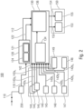
- Fig. 2 shows a block diagram of a device 100 according to an embodiment of the present invention.
- the device 100 is designed to receive a speech radio signal 110, which can represent a speech signal (e.g. analog or digital), by means of a radio device 230 (receiver).
- the speech radio signal 110 can thus be transmitted by an object and received by the radio device 230.
- the device 100 can optionally have the radio device 230, whereby the device 100 can therefore also be designed to send out a speech radio signal 110 with the radio device 230 and at the same time further process the specially transmitted speech radio signal 110 using the device 100.
- the radio device 230 can be any radio device or any voice signal source (aircraft radio band for aviation radio, marine radio band for marine radio and/or BOS radio for land radio).
- the voice radio signal 110 can be sent to a transcription unit 120 of the device 100 from a radio receiver of the radio device 230 so that the device 100 can process the voice radio signal 110.
- the transcription unit 120 can be understood as an automatic transcription system of radio messages, wherein the transcription unit 120 is designed to convert the speech radio signal 110 into a text signal 112.
- the transcription unit 120 can have a speech recognition 124, which can convert the speech radio signal 110 into the text signal 112 (for example into a message in text form (e.g. ASCII)).
- the transcription unit 120 can have, for example, a speech pattern identification 121, whereby the transcription unit 120 can be designed to extract a speech pattern code 122 from the speech radio signal 110 and to provide it to an object determination unit 130 of the device 100.
- the speech pattern code 122 can form a unique ID associated with the radio message pattern, with which an object from which the speech radio signal 110 originates can be identified.
- the identification using a voice pattern code can be carried out by the object determination unit 130.
- the transcription unit 120 is designed to use a neural network to convert the speech radio signal 110 into the text signal 112.
- the device 100 has an object localization unit 140, which is designed to determine position information 142 of the object from which the speech radio signal 110 originates.
- the object localization unit 140 has at least one radio direction finder 144 1 to 144 n (e.g. part of a localization device) in order to determine bearing data 142a to 142a n as position information 142.
- the object localization unit 140 can have n radio direction finders 144 1 to 144 n or can be designed to communicate with n radio direction finders 144 1 to 144 n , where n represents a positive integer.
- the object localization unit 140 can thus use the radio direction finders 144 1 to 144 n to determine the direction of a radio signal, e.g. B.
- the speech radio signal 110 with the use of several direction finders 144 1 to 144 n enabling the position of the radio source to be determined. If only one radio direction finder is used, only a rough area in which the radio source (the object) is arranged can be determined as position information 142, for example. However, if several direction finders 144 1 to 144 n are present and used, a very precise position of the radio source can be determined using the object localization unit 140, for example by means of cross bearing.
- the object localization unit 140 further comprises or is designed to communicate with a general position data receiver 148 and optionally further a GPS receiver 145, an ADS-B receiver 146, an AIS receiver 147, and/or a compass 149 the position data, such as B. GPS data 142b 1 , ADS-B data 142b 2 , AIS data 142b 3 and / or other other general position data 142b 4 and 142b 5 to receive.
- the position data 142b to 142b 5 may include positions of objects located in an area in which the device 100 has determined an origin of the speech radio signal 110 with a certain probability. This area can emerge, for example, from the bearing data 142a 1 to 142a n .
- the object localization unit 140 can also have a radar system or be designed to communicate with it in order to obtain further or alternative position data to recieve.
- the GPS receiver 145 can be designed to determine the device 100's own position.
- the compass 149 can be used additionally or alternatively, whereby it determines its own heading, e.g. B. the object in which the device 100 is arranged can be determined.
- the determination of one's own position or one's own orientation is advantageous in that the position of objects from which the speech radio signal 110 originates is determined very quickly, efficiently and in relation to the position or orientation of the device 100 or the object can be determined with the device 100.
- the ADS-B receiver 146 can be designed to determine the position of ADS-B emitting objects, such as. B. a position of aircraft in the area.
- the AIS receiver 147 can be designed to determine the position of AIS-emitting objects, such as. B. a position of ships in the area.
- the general position data receiver 148 can be designed to determine the position and identification of any objects, such as. B. land vehicles.
- the object localization unit 140 thus makes it possible to locate a wide variety of objects, such as. B. ships, aircraft and / or land vehicles to locate.
- the position data 142b 1 to 142b 5 may be GPS positions, a route, a speed and/or an altitude based on sea level.
- the device 100 also has the object determination unit 130, which is designed to determine an object from which the speech radio signal 110 originates.
- the object determination unit 130 can also be referred to as automatic object identification with position determination.
- the object determination unit 130 receives the text signal 112 and/or the speech pattern code 122 from the transcription unit 120 and the position information 142, which indicates an area from which the speech radio signal comes, from the object localization unit 140 as bearing data 142a to 142a n may include and may include position data 142b 1 to 142b 5 .
- the object determination unit 130 can be divided into two processing units.
- a first processing unit 134 can be formed be for general object recognition, such as B. to carry out ship detection, aircraft detection and / or land travel detection.
- the first processing unit 134 can process the position information 142.
- the object determination unit 130 is designed to compare the position data 142b to 142b 5 of the position information 142 with the bearing data 142a to 142a n of the position information 142 in order to determine objects that have a certain detection probability (which the object determination unit 130 can determine). Speech radio signal 110 comes from.
- the position information 142 includes a position or area (e.g., the bearing data 142a 1 to 142a n ) from which the voice radio signal 110 originates, and general position data 142b 1 to 142b 5 , the positions of all objects in an environment the device 100 may have.
- the object determination unit 130 is designed to determine a match between the position data 142b, to 142b 5 and the bearing data 142a, to 142a n and to assign a detection probability to the objects determined in this way, whereby the detection probability can be dependent on the match.
- the first processing unit 134 carries out, for example, an identification and position determination of objects (ships, aircraft or land vehicles) that send a radio signal 110 with a detection probability.
- the detection probability defines a degree of agreement of the determined position information 142a 1 to 142a n with an actual position 142b 1 to 142b 4 of an object.
- the object determination unit 130 can be designed to determine the detection probability based on probabilities of correct position information 142 of the object localization unit 140, where correct can mean that the position data receivers 145, 146, 147, 148, 149 have an inaccuracy in the determination of the position data 142b 1 to 142b 5 have less than a lower limit value.
- the objects recognized in this way (e.g. watercraft, aircraft or land vehicles) with the detection probability, the position, the course and/or further data are transmitted to a second processing unit 136 of the object determination unit 130 by the first processing unit 134.
- the object determination unit 130 e.g. B. by means of the second processing unit 136, be designed to apply an algorithm for object data preparation to the recognized objects (e.g. by means of the first processing unit 134).
- the algorithm can be used to obtain a summary of all of them Air, water and land vehicles and on the other hand the information about the vehicles (position, course, etc.), radio message text 112, voice pattern code 122, bearing, etc. can be combined into one or more objects.
- the object determination unit 130 can be designed to determine the object with the highest probability of detection as the object from which the speech radio signal 110 originates and thus reduce all detected objects to one object.
- the object determination unit 130 is designed to determine an object identification of the object from the text signal 112 and thus reduce the recognized objects to this one object.
- the object determination unit can be designed to determine the object from which the speech radio signal originates based on the speech pattern code 122 and thus to reduce the detected objects to this one object.
- the object determination unit 130 can combine the data into multiple objects if several voice radio signals 110 are processed simultaneously by the device 100, or if the algorithm for object data preparation determines multiple objects that are considered for the transmission of the voice radio signal 110 become.
- the device 100 also has an output unit 150, which is designed to assign and provide the text signal 112 to the object.
- the output unit 150 may have an interface 152 for a data protocol and/or an internal graphical interface 154.
- the data determined by the device 100 e.g. text signal together with object identification and position and time
- the data can be sent be transmitted to an external device or to external software in order to provide the data there for a user of the device 100.
- the data can be transmitted to ECDIS 153 and thus displayed in an electronic nautical chart.
- the data is displayed on a monitor 155, which the device 100 has, via the internal graphical interface 154.
- the output unit 150 can be designed to assign at least two text signals 112 of at least two speech radio signals 110 to the respective object and sort them in time via a user interface of the device (for example the monitor 155) and / or in a database (for example via the interface 152).
- Fig. 2 shows a device, system and method which automatically writes down voice messages transmitted via VHF marine radio or aviation radio (e.g. the voice radio signal 110), e.g. B. represents and optionally ensures a reliable (sender) assignment of each received voice message by linking various information and communication technologies on board (AIS, ADS-B, GPS and radio direction finding systems).
- VHF marine radio or aviation radio e.g. the voice radio signal 110
- B. represents and optionally ensures a reliable (sender) assignment of each received voice message by linking various information and communication technologies on board (AIS, ADS-B, GPS and radio direction finding systems).
- AIS information and communication technologies on board
- ADS-B GPS and radio direction finding systems
- the system e.g. the device 100
- the system consists of one or more computer systems and e.g. B. other data sources that are processed as input data.
- the system has an internal graphical interface 154, which is suitable for displaying voice messages (e.g. the speech radio signal 110 as a text signal 112) and identified objects on any monitor 155.
- the system provides a data protocol interface 152 (e.g. NMEA), which can be processed by other information systems (e.g. ECDIS - Electronic Chart Display Information System 153) (see Fig. 2 ).
- processing takes place in 3 steps.
- the analog or digital radio message (e.g. the speech radio signal 110) is first transcribed using an automatic transcription system 120 in e.g. B. an ASCII text message 112 converted.
- the sender is targeted by one or more direction finding systems 144 1 - 144 n .
- the algorithm for automatic object identification e.g. using the object determination unit 130
- position determination z e.g. the sender (e.g. the object) of the radio message is identified and its position is determined.
- the detected objects include e.g. B. a corresponding detection or identification probability is specified.
- the text message 112 of the radio message 110 is assigned to the corresponding object.
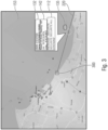
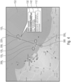
- Fig. 3 to 5 represent a possible representation of the graphical interface 154 based on a maritime application.
- Other applications e.g. B. in aviation or other areas of application would follow the same logic.
- Fig. 3 shows a graphical representation of a transcribed radio message 112 (e.g. text signal) of a watercraft identified as the sender (100% identification probability 135 (e.g. recognition probability)) in an electronic nautical chart 153 according to an exemplary embodiment of the present invention. Furthermore, the radio message 112 is assigned an object or an object identification 132 and optionally position information 142.
- a transcribed radio message 112 e.g. text signal
- the sender 100% identification probability 135 (e.g. recognition probability)
- the radio message 112 is assigned an object or an object identification 132 and optionally position information 142.
- Fig. 4 shows a graphical representation of a transcribed radio message 112 (e.g. text signal) with three possible watercraft (e.g. the objects 200 1 to 200 3 ) in an electronic nautical chart 153, wherein the transcribed radio message 112 corresponds to the object 200 1 with object identification 132 and position information 142 is assigned with a highest identification probability 135 1 of 80% (e.g. recognition probability).
- the device according to the invention can determine an identification probability 135 1 to 135 3 and assign this to the respective object.
- Fig. 5 shows a graphic representation of an electronic nautical chart 153 when an identification of a sender cannot be clearly determined using the device.
- the device 100 can be arranged in a land station 300.
- the device can be designed to determine an area 220 in which the object from which the speech radio signal originates is located with a probability of 135, 135 1 to 135 3 .
- the area 220 may be a direction finding beam, determined using a radio direction finder.
- Fig. 6 shows a block diagram of a method 1000 for processing a speech radio signal, the method comprising a conversion 1100 of the speech radio signal into a text signal by means of a transcription unit. Furthermore, the method 1000 has a determination 1200 of an object from which the speech radio signal originates by means of an object determination unit. Furthermore, the method 1000 has a determination 1300 of position information of the object from which the speech radio signal originates by means of an object localization unit, an assignment 1400 of the text signal to the object and a provision 1500 of the text signal assigned to the object by means of an output unit.
- aspects have been described in connection with a device, it is understood that these aspects also represent a description of the corresponding method, so that a block or a component of a device is also to be understood as a corresponding method step or as a feature of a method step. Similarly, aspects described in connection with or as a method step also represent a description of a corresponding block or detail or feature of a corresponding device.
- Some or all of the method steps may be performed by a hardware apparatus (or using a hardware device). ware apparatus), such as a microprocessor, a programmable computer or an electronic circuit. In some embodiments, some or more of the key process steps may be performed by such apparatus.
- embodiments of the invention may be implemented in hardware or in software.
- the implementation may be using a digital storage medium such as a floppy disk, a DVD, a Blu-ray Disc, a CD, a ROM, a PROM, an EPROM, an EEPROM or a FLASH memory, a hard drive or other magnetic or optical memory are carried out on which electronically readable control signals are stored, which can interact or interact with a programmable computer system in such a way that the respective method is carried out. Therefore, the digital storage medium can be computer readable.
- Some exemplary embodiments according to the invention therefore include a data carrier which has electronically readable control signals which are capable of being programmable Computer system to interact in such a way that one of the methods described herein is carried out.
- embodiments of the present invention may be implemented as a computer program product with a program code, the program code being effective to perform one of the methods when the computer program product runs on a computer.
- the program code can, for example, also be stored on a machine-readable medium.
- inventions include the computer program for performing one of the methods described herein, the computer program being stored on a machine-readable medium.
- an exemplary embodiment of the method according to the invention is therefore a computer program that has a program code for carrying out one of the methods described herein when the computer program runs on a computer.
- a further exemplary embodiment of the method according to the invention is therefore a data carrier (or a digital storage medium or a computer-readable medium) on which the computer program for carrying out one of the methods described herein is recorded.
- the data carrier, digital storage medium or computer-readable medium is typically tangible and/or non-perishable.
- a further exemplary embodiment of the method according to the invention is therefore a data stream or a sequence of signals which represents the computer program for carrying out one of the methods described herein.
- the data stream or the sequence of signals can, for example, be configured to be transferred via a data communication connection, for example via the Internet.
- Another embodiment includes a processing device, such as a computer or a programmable logic device, configured or adapted to perform one of the methods described herein.
- a processing device such as a computer or a programmable logic device, configured or adapted to perform one of the methods described herein.
- Another embodiment includes a computer on which the computer program for performing one of the methods described herein is installed.
- a further embodiment according to the invention includes a device or system designed to transmit a computer program to a receiver for carrying out at least one of the methods described herein.
- the transmission can take place electronically or optically, for example.
- the recipient may be, for example, a computer, a mobile device, a storage device or a similar device.
- the device or system can, for example, comprise a file server for transmitting the computer program to the recipient.
- a programmable logic device e.g., a field programmable gate array, an FPGA
- a field programmable gate array may cooperate with a microprocessor to perform any of the methods described herein.
- the methods are performed by any hardware device. This can be universally applicable hardware such as a computer processor (CPU) or hardware specific to the method, such as an ASIC.
- the devices described herein may be implemented, for example, using a hardware apparatus, or using a computer, or using a combination of a hardware apparatus and a computer.
- the devices described herein, or any components of the devices described herein may be at least partially implemented in hardware and/or in software (computer program).
- the methods described herein may be implemented, for example, using a hardware apparatus, or using a computer, or using a combination of a hardware apparatus and a computer.
Landscapes
- Engineering & Computer Science (AREA)
- Physics & Mathematics (AREA)
- General Physics & Mathematics (AREA)
- Radar, Positioning & Navigation (AREA)
- Health & Medical Sciences (AREA)
- Remote Sensing (AREA)
- Computational Linguistics (AREA)
- Acoustics & Sound (AREA)
- Human Computer Interaction (AREA)
- Audiology, Speech & Language Pathology (AREA)
- Multimedia (AREA)
- Aviation & Aerospace Engineering (AREA)
- Theoretical Computer Science (AREA)
- Artificial Intelligence (AREA)
- Evolutionary Computation (AREA)
- Ocean & Marine Engineering (AREA)
- Biomedical Technology (AREA)
- General Health & Medical Sciences (AREA)
- Mathematical Physics (AREA)
- General Engineering & Computer Science (AREA)
- Computing Systems (AREA)
- Molecular Biology (AREA)
- Computer Vision & Pattern Recognition (AREA)
- Software Systems (AREA)
- Data Mining & Analysis (AREA)
- Biophysics (AREA)
- Life Sciences & Earth Sciences (AREA)
- Traffic Control Systems (AREA)
- Navigation (AREA)
- Position Fixing By Use Of Radio Waves (AREA)
- Radar Systems Or Details Thereof (AREA)
Claims (12)
- Dispositif (100) de traitement d'un signal radio vocal (110), aux caractéristiques suivantes:une unité de transcription (120) qui est conçue pour convertir le signal radio vocal (110) en un signal de texte (112);une unité de détermination d'objet (130) qui est conçue pour déterminer un objet (200) duquel provient le signal radio vocal (110);une unité de localisation d'objet (140) qui est conçue pour déterminer une information de position (142) de l'objet (200) duquel provient le signal radio vocal (110),dans lequel l'unité de localisation d'objet (140) comporte au moins un radiogoniomètre (1441 à 144n) qui est conçu pour déterminer les données de goniométrie (142a1 à 142an) qui indiquent une position ou une région de laquelle provient le signal radio vocal (110), etdans lequel l'unité de localisation d'objet (140) comporte par ailleurs un récepteur de données de position ou est conçue pour communiquer avec ce dernier pour obtenir les données de position (142b1 à 142b5) qui indiquent les positions d'objets dans les environs du dispositif (100),dans lequel les données de goniométrie (142a1 à 142an) forment, ensemble avec les données de position (142b1 à 142b5), les informations de position (142);une unité de sortie (150) qui est conçue pour associer le signal de texte (112) à l'objet (200) et le mettre à disposition; etdans lequel l'unité de détermination d'objet (130) est conçue pour déterminer, pour chacun des objets dans les environs du dispositif (100), une probabilité de reconnaissance (135, 1351 à 1353), dans lequel la probabilité de reconnaissance définit un degré de coïncidence des données de position (142bi à 142bs) avec les données de goniométrie (142ai à 142an), etdans lequel l'unité de détermination d'objet (130) est conçue pour déterminer, dans le cas de plusieurs objets avec une probabilité de reconnaissance très similaire, tous les objets avec la probabilité de reconnaissance similaire comme l'objet (200) duquel provient le signal radio vocal (110), dans lequel l'unité de sortie est conçue pour associer, dans ce cas, au signal de texte tous ces objets à la probabilité de reconnaissance similaire et pour spécifier chaque fois également la probabilité de reconnaissance.
- Dispositif (100) selon la revendication 1, dans lequel le récepteur de données de position présente un récepteur AIS (147), un récepteur ADS-B (146) et/ou une installation radar destiné à recevoir les données de position (142bi à 142bs), et
dans lequel les données de position (142bi à 142bs) présentent une position GPS, un itinéraire, une vitesse et/ou une altitude par rapport au niveau de la mer. - Dispositif (100) selon la revendication 1 ou la revendication 2, dans lequel l'unité de détermination d'objet (130) présente un récepteur AIS (147), un récepteur ADS-B (146) et/ou un récepteur d'identification d'objet général ou est conçue pour communiquer avec ce dernier pour obtenir les données d'identification d'objet (132) d'au moins un objet (200) dont la position (210) coïncide au moins en partie avec l'information de position (142) déterminée par l'unité de localisation d'objet (140).
- Dispositif (100) selon la revendication 3, dans lequel les données d'identification d'objet (132) présentent un numéro d'appel du service mobile de radiocommunication maritime (MMSI), un nom d'objet, une destination de l'objet (200), une charge de l'objet (200) et/ou une grandeur de l'objet (200).
- Dispositif (100) selon l'une des revendications 1 à 4, dans lequel l'unité de détermination d'objet (130) est conçue pour communiquer avec l'unité de transcription (120) pour déterminer à partir du signal de texte (112) les données d'identification d'objet (132) de l'objet (200).
- Dispositif (100) selon l'une des revendications 1 à 5, dans lequel l'unité de transcription (120) est conçue pour extraire du signal radio vocal (110) un code de modèle vocal (122) et pour le mettre à disposition de l'unité de détermination d'objet (130),
dans lequel l'unité de détermination d'objet (130) est conçue pour déterminer, sur base du code de modèle vocal (122), l'objet (200) duquel provient le signal radio vocal (110). - Dispositif (100) selon l'une des revendications 1 à 6, dans lequel l'unité de transcription (120) est conçue pour utiliser un réseau neuronal pour convertir le signal radio vocal (110) en un signal de texte (112).
- Dispositif (100) selon l'une des revendications 1 à 7, dans lequel le dispositif (100) est conçu pour traiter simultanément et/ou de manière décalée dans le temps au moins deux signaux radio vocaux (110), et
dans lequel l'unité de sortie (150) est conçue pour associer au moins deux signaux de texte (112) des au moins deux signaux radio vocaux (110) à l'objet respectif (200) et pour les mettre à disposition de manière triée dans le temps par l'intermédiaire d'une interface d'utilisateur (155) du dispositif (100) et/ou pour les mémoriser dans une base de données. - Dispositif (100) selon l'une des revendications 1 à 8, dans lequel l'unité de sortie (150) est conçue pour mettre à disposition tant le signal de texte (112), un objet associé (200), une position (210) de l'objet (200) ainsi qu'un moment d'entrée du signal radio vocal par l'intermédiaire d'une interface d'utilisateur (155) du dispositif (100) et/ou les mémoriser dans une base de données.
- Dispositif (100) selon l'une des revendications 1 à 9, dans lequel l'objet (200) constitue un navire, un avion ou un véhicule.
- Procédé (1000) pour traiter un signal radio vocal, dans lequel le procédé présente les étapes suivantes consistant à:convertir (1100) le signal radio vocal en un signal de texte au moyen d'une unité de transcription;déterminer (1200) un objet duquel provient le signal radio vocal au moyen d'une unité de détermination d'objet;déterminer (1300) une information de position de l'objet duquel provient le signal radio vocal au moyen d'une unité de localisation d'objet,dans lequel l'unité de localisation d'objet (140) comporte au moins un radiogoniomètre (1441 à 144n) qui est conçu pour déterminer les données de goniométrie qui indiquent une position ou une région de laquelle provient le signal radio vocal, etdans lequel l'unité de localisation d'objet comporte par ailleurs un récepteur de données de position ou est conçue pour communiquer avec ce dernier pour obtenir les données de position qui indiquent les positions d'objets dans les environs du dispositif,dans lequel les données de goniométrie forment, ensemble avec les données de position, les informations de position;associer (1400) le signal de texte à l'objet et mettre à disposition (1500) le signal de texte associé à l'objet au moyen d'une unité de sortie;dans lequel la détermination (1200) de l'objet présente le fait de déterminer une probabilité de reconnaissance pour les objets dans les environs du dispositif et de déterminer, dans le cas de plusieurs objets avec une probabilité de reconnaissance très similaire, tous les objets avec la probabilité de reconnaissance similaire comme l'objet duquel provient le signal radio vocal,dans lequel la probabilité de reconnaissance définit un degré de coïncidence des données de position avec les données de goniométrie, etdans lequel, dans le cas de probabilités de reconnaissance très similaires, tous ces objets avec la probabilité de reconnaissance similaire sont associés au signal de texte (1400) et la probabilité de reconnaissance est chaque fois également indiquée.
- Programme d'ordinateur avec un code de programme pour mettre en oeuvre le procédé selon la revendication 11 lorsque le programme est exécuté sur un ordinateur.
Applications Claiming Priority (2)
| Application Number | Priority Date | Filing Date | Title |
|---|---|---|---|
| EP18211076.7A EP3664065A1 (fr) | 2018-12-07 | 2018-12-07 | Appareil, méthode et programme d'ordinateur pour traiter des signaux radio vocaux |
| PCT/EP2019/081751 WO2020114764A1 (fr) | 2018-12-07 | 2019-11-19 | Dispositif, procédé et programme informatique pour traiter un signal radio vocal |
Publications (3)
| Publication Number | Publication Date |
|---|---|
| EP3891718A1 EP3891718A1 (fr) | 2021-10-13 |
| EP3891718C0 EP3891718C0 (fr) | 2023-09-13 |
| EP3891718B1 true EP3891718B1 (fr) | 2023-09-13 |
Family
ID=64661195
Family Applications (2)
| Application Number | Title | Priority Date | Filing Date |
|---|---|---|---|
| EP18211076.7A Withdrawn EP3664065A1 (fr) | 2018-12-07 | 2018-12-07 | Appareil, méthode et programme d'ordinateur pour traiter des signaux radio vocaux |
| EP19808725.6A Active EP3891718B1 (fr) | 2018-12-07 | 2019-11-19 | Appareil, méthode et programme d'ordinateur pour traiter des signaux radio vocaux |
Family Applications Before (1)
| Application Number | Title | Priority Date | Filing Date |
|---|---|---|---|
| EP18211076.7A Withdrawn EP3664065A1 (fr) | 2018-12-07 | 2018-12-07 | Appareil, méthode et programme d'ordinateur pour traiter des signaux radio vocaux |
Country Status (8)
| Country | Link |
|---|---|
| US (1) | US12007492B2 (fr) |
| EP (2) | EP3664065A1 (fr) |
| JP (1) | JP7187699B2 (fr) |
| KR (1) | KR102625050B1 (fr) |
| CN (1) | CN113424244B (fr) |
| CA (1) | CA3122144A1 (fr) |
| ES (1) | ES2967758T3 (fr) |
| WO (1) | WO2020114764A1 (fr) |
Families Citing this family (10)
| Publication number | Priority date | Publication date | Assignee | Title |
|---|---|---|---|---|
| US12190861B2 (en) | 2021-04-22 | 2025-01-07 | Honeywell International Inc. | Adaptive speech recognition methods and systems |
| US12431025B2 (en) | 2021-06-16 | 2025-09-30 | Honeywell International Inc. | Contextual transcription augmentation methods and systems |
| JP7776301B2 (ja) * | 2021-10-06 | 2025-11-26 | 日本無線株式会社 | 国際vhf通信を利用した他船表示方法 |
| JP2023068874A (ja) * | 2021-11-04 | 2023-05-18 | 株式会社東芝 | 電波発射源監視装置及び電波発射源監視方法 |
| US12603086B2 (en) | 2022-01-05 | 2026-04-14 | Honeywell International Inc. | Contextual editable speech recognition methods and systems |
| US12505751B2 (en) | 2022-05-12 | 2025-12-23 | Honeywell International Inc. | Transcription systems and related supplementation methods |
| AT526211B1 (de) * | 2022-05-24 | 2024-03-15 | Frequentis Ag | Verfahren zur Verbesserung der Wiedergabequalität von Audiosignalen, sowie Kommunikationssystem zur Durchführung des Verfahrens |
| US12437156B2 (en) | 2022-10-28 | 2025-10-07 | Honeywell International Inc. | Transcription systems and methods for challenging clearances |
| US12322392B1 (en) | 2023-12-04 | 2025-06-03 | TDI Novus, Inc. | Automated system and method that services inquiring vessels |
| JP7802406B1 (ja) * | 2024-12-09 | 2026-01-20 | 容九 辛 | 船舶の安全航海支援システム |
Citations (3)
| Publication number | Priority date | Publication date | Assignee | Title |
|---|---|---|---|---|
| US3824596A (en) * | 1972-09-27 | 1974-07-16 | Southwest Res Inst | Automatic sector indicating direction finder system |
| US20130346081A1 (en) * | 2012-06-11 | 2013-12-26 | Airbus (Sas) | Device for aiding communication in the aeronautical domain |
| US20160202950A1 (en) * | 2015-01-09 | 2016-07-14 | Garmin International, Inc. | System for managing an avionic communications log |
Family Cites Families (14)
| Publication number | Priority date | Publication date | Assignee | Title |
|---|---|---|---|---|
| JP3484818B2 (ja) * | 1995-05-09 | 2004-01-06 | ソニー株式会社 | 音声認識装置及びナビゲーション装置 |
| DE19619015B4 (de) * | 1996-05-10 | 2006-11-02 | Deutsches Zentrum für Luft- und Raumfahrt e.V. | Verfahren und Anordnung zur Verkehrsüberwachung |
| JP2002048572A (ja) | 2000-08-01 | 2002-02-15 | Alpine Electronics Inc | 位置検出システムおよびナビゲーションシステム |
| US20100029305A1 (en) * | 2008-07-30 | 2010-02-04 | Embarq Holdings Company, Llc | Sms and voice messaging to gps |
| KR101532932B1 (ko) * | 2009-03-02 | 2015-07-01 | 엘지전자 주식회사 | 이동 단말기 및 이를 이용한 스케쥴 관리 방법 및 위치 정보 관리 방법 |
| CN101527085A (zh) * | 2009-04-21 | 2009-09-09 | 中国民航大学 | 一种航班信息即动报知装置及其处理方法 |
| US9686382B2 (en) * | 2014-08-04 | 2017-06-20 | Honeywell International Inc. | Double decoder system for decoding overlapping aircraft surveillance signals |
| AT516219B1 (de) * | 2014-09-09 | 2017-06-15 | Frequentis Ag | Verfahren zur Identifikation und Prüfung von Sprechfunkmeldungen |
| PL3062539T3 (pl) * | 2015-02-26 | 2019-01-31 | C.O.B.O. S.P.A. | Łączenie urządzeń komunikacyjnych na motocyklu |
| US9508262B2 (en) * | 2015-03-26 | 2016-11-29 | Honeywell International Inc. | Systems and methods for voice enabled traffic prioritization |
| KR20170044386A (ko) * | 2015-10-15 | 2017-04-25 | 삼성전자주식회사 | 전자기기 및 전자기기의 제어방법 |
| US9922569B2 (en) * | 2016-02-03 | 2018-03-20 | Honeywell International Inc. | System and method for monitoring a communication channel and displaying information |
| FR3056321B1 (fr) * | 2016-09-19 | 2019-07-19 | Airbus Operations (Sas) | Procede et dispositif d'identification d'un aeronef destinataire d'une communication audio |
| US10157616B2 (en) * | 2016-12-19 | 2018-12-18 | Honeywell International Inc. | Methods and apparatus for post-processing speech recognition results of received radio voice messages onboard an aircraft |
-
2018
- 2018-12-07 EP EP18211076.7A patent/EP3664065A1/fr not_active Withdrawn
-
2019
- 2019-11-19 WO PCT/EP2019/081751 patent/WO2020114764A1/fr not_active Ceased
- 2019-11-19 CN CN201980091650.2A patent/CN113424244B/zh active Active
- 2019-11-19 KR KR1020217021332A patent/KR102625050B1/ko active Active
- 2019-11-19 EP EP19808725.6A patent/EP3891718B1/fr active Active
- 2019-11-19 JP JP2021532425A patent/JP7187699B2/ja active Active
- 2019-11-19 ES ES19808725T patent/ES2967758T3/es active Active
- 2019-11-19 CA CA3122144A patent/CA3122144A1/fr active Pending
-
2021
- 2021-06-04 US US17/338,966 patent/US12007492B2/en active Active
Patent Citations (3)
| Publication number | Priority date | Publication date | Assignee | Title |
|---|---|---|---|---|
| US3824596A (en) * | 1972-09-27 | 1974-07-16 | Southwest Res Inst | Automatic sector indicating direction finder system |
| US20130346081A1 (en) * | 2012-06-11 | 2013-12-26 | Airbus (Sas) | Device for aiding communication in the aeronautical domain |
| US20160202950A1 (en) * | 2015-01-09 | 2016-07-14 | Garmin International, Inc. | System for managing an avionic communications log |
Also Published As
| Publication number | Publication date |
|---|---|
| EP3664065A1 (fr) | 2020-06-10 |
| EP3891718A1 (fr) | 2021-10-13 |
| CN113424244A (zh) | 2021-09-21 |
| CA3122144A1 (fr) | 2020-06-11 |
| CN113424244B (zh) | 2023-04-28 |
| KR20210123294A (ko) | 2021-10-13 |
| ES2967758T3 (es) | 2024-05-03 |
| JP7187699B2 (ja) | 2022-12-12 |
| EP3891718C0 (fr) | 2023-09-13 |
| WO2020114764A1 (fr) | 2020-06-11 |
| US20210295840A1 (en) | 2021-09-23 |
| US12007492B2 (en) | 2024-06-11 |
| KR102625050B1 (ko) | 2024-01-16 |
| JP2022514825A (ja) | 2022-02-16 |
Similar Documents
| Publication | Publication Date | Title |
|---|---|---|
| EP3891718B1 (fr) | Appareil, méthode et programme d'ordinateur pour traiter des signaux radio vocaux | |
| DE3152340C1 (de) | Verfahren und Anordnung zum Bestimmen der Positionen von Fahrzeugen mittels Satelliten | |
| DE102008010882A1 (de) | Vorrichtung und Verfahren zur Richtungsschätzung und/oder Decodierung von Sekundärradarsignalen | |
| DE60007279T2 (de) | Überwachungssystem für terrestrische navigations- und fluglandesysteme | |
| DE102012018637A1 (de) | Vorrichtung zur Warnung vor aerologischen Phänomenen für ein Flugzeug | |
| DE212015000274U1 (de) | Vorrichtung und nichtflüchtiges Computerprogrammprodukt zur Überwachung einer Flugzeugposition | |
| EP0815466B1 (fr) | Dispositif pour surveiller l'ecart entre deux objets | |
| DE102013004463B4 (de) | Vorrichtung und Verfahren zur Detektion von Flugobjekten im Umkreis von Windkraftanlagen | |
| EP2680024B1 (fr) | Système et procédé de détermination de la position d'une plate-forme de communication | |
| EP2065722B1 (fr) | Dispositif destiné au positionnement d'objets ou de personnes, notamment pour une recherche de victimes d'une avalanche et procédé de positionnement | |
| WO2004075139A1 (fr) | Systeme de surveillance du terrain d'un aeroport | |
| DE102015011246A1 (de) | Lokalisation von Signalquellen mittels Kraftfahrzeugen | |
| DE102014101902A1 (de) | Überwachungssystem zum Überwachen sowie Verfahren zum Verifizieren eines Wasserfahrzeugs oder mehrerer Wasserfahrzeuge | |
| DE102010052474A1 (de) | Flugführungssystem | |
| EP2643707B1 (fr) | Système de localisation | |
| DE10015164A1 (de) | Kommunikations-Verfahren mit einem ROSAR-Gerät | |
| DE102013013123B4 (de) | Verfahren und Vorrichtung zur Ortung von Funkstationen mittels Doppler-Effekt an Bord von fliegenden Plattformen | |
| DE19818426C2 (de) | Verfahren zur Fernaufklärung und Zielortung | |
| EP2584374A1 (fr) | Procédé de correction de radiogoniométrie | |
| DE102012006784B4 (de) | Vorrichtung und Verfahren zur Ortung von Funksignalen mittels Doppler-Effekt an Bord von fliegenden Plattformen | |
| DE102017117501A1 (de) | Vorrichtung zum Prüfen der Konsistenz einer Positionsbestimmung | |
| DE102021206181A1 (de) | Verfahren zum Erkennen eines manipulierten oder gefälschten GNSS-Signals | |
| DE102010006706A1 (de) | Ermittlung der Position von Teilnehmern eines insbesondere satellitengestützten Mobilfunksystems | |
| DE3713778A1 (de) | Anordnung und verfahren zur positionsbestimmung und kollisionsverhuetung | |
| Odisho | An evaluation of the traffic alert and collision avoidance system for T-1A cell formation stationkeeping |
Legal Events
| Date | Code | Title | Description |
|---|---|---|---|
| STAA | Information on the status of an ep patent application or granted ep patent |
Free format text: STATUS: UNKNOWN |
|
| STAA | Information on the status of an ep patent application or granted ep patent |
Free format text: STATUS: THE INTERNATIONAL PUBLICATION HAS BEEN MADE |
|
| PUAI | Public reference made under article 153(3) epc to a published international application that has entered the european phase |
Free format text: ORIGINAL CODE: 0009012 |
|
| STAA | Information on the status of an ep patent application or granted ep patent |
Free format text: STATUS: REQUEST FOR EXAMINATION WAS MADE |
|
| 17P | Request for examination filed |
Effective date: 20210531 |
|
| AK | Designated contracting states |
Kind code of ref document: A1 Designated state(s): AL AT BE BG CH CY CZ DE DK EE ES FI FR GB GR HR HU IE IS IT LI LT LU LV MC MK MT NL NO PL PT RO RS SE SI SK SM TR |
|
| DAV | Request for validation of the european patent (deleted) | ||
| DAX | Request for extension of the european patent (deleted) | ||
| RAP3 | Party data changed (applicant data changed or rights of an application transferred) |
Owner name: RHOTHETA ELEKTRONIK GMBH Owner name: FRAUNHOFER-GESELLSCHAFT ZUR FOERDERUNG DER ANGEWANDTEN FORSCHUNG E.V. |
|
| STAA | Information on the status of an ep patent application or granted ep patent |
Free format text: STATUS: EXAMINATION IS IN PROGRESS |
|
| 17Q | First examination report despatched |
Effective date: 20220712 |
|
| REG | Reference to a national code |
Ref country code: DE Ref legal event code: R079 Free format text: PREVIOUS MAIN CLASS: G08G0003000000 Ipc: G08G0005000000 Ref country code: DE Ref legal event code: R079 Ref document number: 502019009381 Country of ref document: DE Free format text: PREVIOUS MAIN CLASS: G08G0003000000 Ipc: G08G0005000000 |
|
| RIC1 | Information provided on ipc code assigned before grant |
Ipc: G10L 15/02 20060101ALI20230126BHEP Ipc: G01S 3/14 20060101ALI20230126BHEP Ipc: G08G 3/00 20060101ALI20230126BHEP Ipc: G08G 5/00 20060101AFI20230126BHEP |
|
| RIC1 | Information provided on ipc code assigned before grant |
Ipc: G01S 3/04 20060101ALI20230216BHEP Ipc: G10L 15/26 20060101ALI20230216BHEP Ipc: G01S 3/14 20060101ALI20230216BHEP Ipc: G08G 3/00 20060101ALI20230216BHEP Ipc: G08G 5/00 20060101AFI20230216BHEP |
|
| GRAP | Despatch of communication of intention to grant a patent |
Free format text: ORIGINAL CODE: EPIDOSNIGR1 |
|
| STAA | Information on the status of an ep patent application or granted ep patent |
Free format text: STATUS: GRANT OF PATENT IS INTENDED |
|
| INTG | Intention to grant announced |
Effective date: 20230324 |
|
| GRAS | Grant fee paid |
Free format text: ORIGINAL CODE: EPIDOSNIGR3 |
|
| GRAA | (expected) grant |
Free format text: ORIGINAL CODE: 0009210 |
|
| STAA | Information on the status of an ep patent application or granted ep patent |
Free format text: STATUS: THE PATENT HAS BEEN GRANTED |
|
| AK | Designated contracting states |
Kind code of ref document: B1 Designated state(s): AL AT BE BG CH CY CZ DE DK EE ES FI FR GB GR HR HU IE IS IT LI LT LU LV MC MK MT NL NO PL PT RO RS SE SI SK SM TR |
|
| REG | Reference to a national code |
Ref country code: CH Ref legal event code: EP |
|
| REG | Reference to a national code |
Ref country code: DE Ref legal event code: R096 Ref document number: 502019009381 Country of ref document: DE |
|
| REG | Reference to a national code |
Ref country code: IE Ref legal event code: FG4D Free format text: LANGUAGE OF EP DOCUMENT: GERMAN |
|
| U01 | Request for unitary effect filed |
Effective date: 20231013 |
|
| U07 | Unitary effect registered |
Designated state(s): AT BE BG DE DK EE FI FR IT LT LU LV MT NL PT SE SI Effective date: 20231023 |
|
| U20 | Renewal fee for the european patent with unitary effect paid |
Year of fee payment: 5 Effective date: 20231018 |
|
| REG | Reference to a national code |
Ref country code: NO Ref legal event code: T2 Effective date: 20230913 |
|
| REG | Reference to a national code |
Ref country code: GR Ref legal event code: EP Ref document number: 20230402437 Country of ref document: GR Effective date: 20240110 |
|
| PG25 | Lapsed in a contracting state [announced via postgrant information from national office to epo] |
Ref country code: RS Free format text: LAPSE BECAUSE OF FAILURE TO SUBMIT A TRANSLATION OF THE DESCRIPTION OR TO PAY THE FEE WITHIN THE PRESCRIBED TIME-LIMIT Effective date: 20230913 Ref country code: HR Free format text: LAPSE BECAUSE OF FAILURE TO SUBMIT A TRANSLATION OF THE DESCRIPTION OR TO PAY THE FEE WITHIN THE PRESCRIBED TIME-LIMIT Effective date: 20230913 |
|
| REG | Reference to a national code |
Ref country code: GB Ref legal event code: 732E Free format text: REGISTERED BETWEEN 20240104 AND 20240110 |
|
| PG25 | Lapsed in a contracting state [announced via postgrant information from national office to epo] |
Ref country code: IS Free format text: LAPSE BECAUSE OF FAILURE TO SUBMIT A TRANSLATION OF THE DESCRIPTION OR TO PAY THE FEE WITHIN THE PRESCRIBED TIME-LIMIT Effective date: 20240113 |
|
| PG25 | Lapsed in a contracting state [announced via postgrant information from national office to epo] |
Ref country code: SM Free format text: LAPSE BECAUSE OF FAILURE TO SUBMIT A TRANSLATION OF THE DESCRIPTION OR TO PAY THE FEE WITHIN THE PRESCRIBED TIME-LIMIT Effective date: 20230913 Ref country code: RO Free format text: LAPSE BECAUSE OF FAILURE TO SUBMIT A TRANSLATION OF THE DESCRIPTION OR TO PAY THE FEE WITHIN THE PRESCRIBED TIME-LIMIT Effective date: 20230913 Ref country code: IS Free format text: LAPSE BECAUSE OF FAILURE TO SUBMIT A TRANSLATION OF THE DESCRIPTION OR TO PAY THE FEE WITHIN THE PRESCRIBED TIME-LIMIT Effective date: 20240113 Ref country code: CZ Free format text: LAPSE BECAUSE OF FAILURE TO SUBMIT A TRANSLATION OF THE DESCRIPTION OR TO PAY THE FEE WITHIN THE PRESCRIBED TIME-LIMIT Effective date: 20230913 Ref country code: SK Free format text: LAPSE BECAUSE OF FAILURE TO SUBMIT A TRANSLATION OF THE DESCRIPTION OR TO PAY THE FEE WITHIN THE PRESCRIBED TIME-LIMIT Effective date: 20230913 |
|
| REG | Reference to a national code |
Ref country code: ES Ref legal event code: FG2A Ref document number: 2967758 Country of ref document: ES Kind code of ref document: T3 Effective date: 20240503 |
|
| PG25 | Lapsed in a contracting state [announced via postgrant information from national office to epo] |
Ref country code: PL Free format text: LAPSE BECAUSE OF FAILURE TO SUBMIT A TRANSLATION OF THE DESCRIPTION OR TO PAY THE FEE WITHIN THE PRESCRIBED TIME-LIMIT Effective date: 20230913 |
|
| REG | Reference to a national code |
Ref country code: DE Ref legal event code: R097 Ref document number: 502019009381 Country of ref document: DE |
|
| REG | Reference to a national code |
Ref country code: CH Ref legal event code: PL |
|
| PG25 | Lapsed in a contracting state [announced via postgrant information from national office to epo] |
Ref country code: MC Free format text: LAPSE BECAUSE OF FAILURE TO SUBMIT A TRANSLATION OF THE DESCRIPTION OR TO PAY THE FEE WITHIN THE PRESCRIBED TIME-LIMIT Effective date: 20230913 |
|
| PG25 | Lapsed in a contracting state [announced via postgrant information from national office to epo] |
Ref country code: CH Free format text: LAPSE BECAUSE OF NON-PAYMENT OF DUE FEES Effective date: 20231130 |
|
| PLBE | No opposition filed within time limit |
Free format text: ORIGINAL CODE: 0009261 |
|
| STAA | Information on the status of an ep patent application or granted ep patent |
Free format text: STATUS: NO OPPOSITION FILED WITHIN TIME LIMIT |
|
| PG25 | Lapsed in a contracting state [announced via postgrant information from national office to epo] |
Ref country code: MC Free format text: LAPSE BECAUSE OF FAILURE TO SUBMIT A TRANSLATION OF THE DESCRIPTION OR TO PAY THE FEE WITHIN THE PRESCRIBED TIME-LIMIT Effective date: 20230913 Ref country code: CH Free format text: LAPSE BECAUSE OF NON-PAYMENT OF DUE FEES Effective date: 20231130 |
|
| 26N | No opposition filed |
Effective date: 20240614 |
|
| REG | Reference to a national code |
Ref country code: IE Ref legal event code: MM4A |
|
| REG | Reference to a national code |
Ref country code: ES Ref legal event code: PC2A Owner name: FRAUNHOFER-GESELLSCHAFT ZUR FOERDERUNGDER ANGEWANDTEN FORSCHUNG E.V. Effective date: 20240930 |
|
| PG25 | Lapsed in a contracting state [announced via postgrant information from national office to epo] |
Ref country code: IE Free format text: LAPSE BECAUSE OF NON-PAYMENT OF DUE FEES Effective date: 20231119 |
|
| PG25 | Lapsed in a contracting state [announced via postgrant information from national office to epo] |
Ref country code: IE Free format text: LAPSE BECAUSE OF NON-PAYMENT OF DUE FEES Effective date: 20231119 |
|
| U20 | Renewal fee for the european patent with unitary effect paid |
Year of fee payment: 6 Effective date: 20241107 |
|
| PG25 | Lapsed in a contracting state [announced via postgrant information from national office to epo] |
Ref country code: HU Free format text: LAPSE BECAUSE OF FAILURE TO SUBMIT A TRANSLATION OF THE DESCRIPTION OR TO PAY THE FEE WITHIN THE PRESCRIBED TIME-LIMIT; INVALID AB INITIO Effective date: 20191119 |
|
| U20 | Renewal fee for the european patent with unitary effect paid |
Year of fee payment: 7 Effective date: 20251031 |
|
| PG25 | Lapsed in a contracting state [announced via postgrant information from national office to epo] |
Ref country code: TR Free format text: LAPSE BECAUSE OF FAILURE TO SUBMIT A TRANSLATION OF THE DESCRIPTION OR TO PAY THE FEE WITHIN THE PRESCRIBED TIME-LIMIT Effective date: 20230913 |
|
| PGFP | Annual fee paid to national office [announced via postgrant information from national office to epo] |
Ref country code: GB Payment date: 20251120 Year of fee payment: 7 |
|
| PGFP | Annual fee paid to national office [announced via postgrant information from national office to epo] |
Ref country code: NO Payment date: 20251118 Year of fee payment: 7 |
|
| PGFP | Annual fee paid to national office [announced via postgrant information from national office to epo] |
Ref country code: GR Payment date: 20251117 Year of fee payment: 7 |
|
| PGFP | Annual fee paid to national office [announced via postgrant information from national office to epo] |
Ref country code: CY Payment date: 20251114 Year of fee payment: 7 |
|
| PGFP | Annual fee paid to national office [announced via postgrant information from national office to epo] |
Ref country code: ES Payment date: 20251216 Year of fee payment: 7 |