EP3892079A1 - Verfahren zur einstellung eines zentrfugalstreuers für teilchen und entsprechender zentrfugalstreuer für teilchen - Google Patents
Verfahren zur einstellung eines zentrfugalstreuers für teilchen und entsprechender zentrfugalstreuer für teilchen Download PDFInfo
- Publication number
- EP3892079A1 EP3892079A1 EP21167920.4A EP21167920A EP3892079A1 EP 3892079 A1 EP3892079 A1 EP 3892079A1 EP 21167920 A EP21167920 A EP 21167920A EP 3892079 A1 EP3892079 A1 EP 3892079A1
- Authority
- EP
- European Patent Office
- Prior art keywords
- speed
- correction
- spreader
- particles
- effect
- Prior art date
- Legal status (The legal status is an assumption and is not a legal conclusion. Google has not performed a legal analysis and makes no representation as to the accuracy of the status listed.)
- Granted
Links
Images








Classifications
-
- A—HUMAN NECESSITIES
- A01—AGRICULTURE; FORESTRY; ANIMAL HUSBANDRY; HUNTING; TRAPPING; FISHING
- A01C—PLANTING; SOWING; FERTILISING
- A01C17/00—Fertilisers or seeders with centrifugal wheels
- A01C17/001—Centrifugal throwing devices with a vertical axis
-
- A—HUMAN NECESSITIES
- A01—AGRICULTURE; FORESTRY; ANIMAL HUSBANDRY; HUNTING; TRAPPING; FISHING
- A01C—PLANTING; SOWING; FERTILISING
- A01C17/00—Fertilisers or seeders with centrifugal wheels
- A01C17/006—Regulating or dosing devices
- A01C17/008—Devices controlling the quantity or the distribution pattern
-
- A—HUMAN NECESSITIES
- A01—AGRICULTURE; FORESTRY; ANIMAL HUSBANDRY; HUNTING; TRAPPING; FISHING
- A01C—PLANTING; SOWING; FERTILISING
- A01C21/00—Methods of fertilising, sowing or planting
Definitions
- the present invention relates to the field of techniques for spreading particles, in the field of agriculture, or of products in the form of grains, such as fertilizers.
- the present invention relates to a method of adjusting a centrifugal particle spreader and a centrifugal particle spreader.
- the target working width depends on the cultivation activities carried out before spreading.
- the spreader is adjusted to suit the plot, such as respecting a given working width. In the absence of these adjustments, defects appear, for example over- and under-dosing in bands along the path followed by the spreader.
- the product to be spread can in particular be stored in a hopper, and brought or discharged above each disc by a transfer member, for example by a movable chute above the disc or via one or more openings which can be partially closed by a hatch, so as to be projected through the blades on the ground on which it is to be placed.
- the web on the ground defined by the products distributed during spreading is generally semi-annular in shape, or crescent-shaped (with reference to the croissant of viennoiserie), the width in the middle of the web being greater than the width at the bottom. level of each of the points, as shown in the figure 1A .
- the location of the centrifugal spreader for example carried by a vehicle such as a tractor, is symbolized by a cross placed at the point of origin O of a plane (X, Y) representing the ground.
- the web shown is the result of the complete distribution process, i.e. it is an imprint of the product distribution when the centrifugal spreader is in operation. It should be noted that the density of the product distributed is not the same at all points of the web, see below the figure 4 .
- the process of obtaining the slick takes place by considering a spreader in the stopped position, for example for rotary beds of Cemib type (registered trademark) or at low speed (for example for transverse beds, for which the speed is of the order of 4 to 8 km.
- a spreader in the stopped position for example for rotary beds of Cemib type (registered trademark) or at low speed (for example for transverse beds, for which the speed is of the order of 4 to 8 km.
- a target dose that is to say a quantity of particles desired per unit of floor area
- a target flow rate of particles is determined which must be deposited on the spreading disc (s), a function of the target dose, of a target working width and of the speed.
- This flow rate effect therefore requires a correction aimed at keeping the transverse distribution unchanged when the flow rate is modified.
- This correction takes into account the quantity of particles per unit of time delivered.
- centrifugal spreaders make it possible to adjust the spreaders so as to obtain a given working width.
- these settings are determined on a test bench thanks to measurements taken at zero or almost zero speed, and then they do not take into account the effect of this displacement speed on the working width such as previously described.
- Numerous devices for managing the spreading parameters are known, for example systems for regulating the flow rate of product supplied to the distributor discs, of the DPA (for Flow rate proportional to Advancement) or DPAE (for Flow rate proportional to Advancement) type. Electronic). These systems make it possible to adjust the flow rate according to the forward speed of the vehicle. An example of this approach is described in the patent document EP0472855 .
- the inventors have however observed that this correction of the flow effect was not sufficient in all situations, and that the slick on the ground varied appreciably as a function of the speed of movement of the spreader.
- the figure 1B illustrates the qualitative impact of the speed of movement of the centrifugal spreader on the spreading sheet.
- the movement of the centrifugal spreader (or of the vehicle on which it is mounted) is symbolized by an arrow in thick line from the origin point O and directed in the direction of the increasing Y ordinates.
- the spreading layer conventionally taken into account, formed by the stationary centrifugal spreader, as illustrated in figure 1A is shown in broken lines.
- the spreading sheet formed by the moving centrifugal spreader at an approximate speed of 20 km / h, is shown in solid lines. Of course, in this case, only the spreading layer attributable to the centrifugal spreader at point O is shown.
- the speed of movement deforms the web produced on the ground, in particular in the direction of movement of the centrifugal spreader.
- Arrows distributed all along the periphery of the spreading sheet symbolize the deformation of the spreading sheet when one passes from the sheet formed by the centrifugal spreader without displacement speed to that formed with speed.
- the amplitude of the deformation is symbolized by the length of the arrows. It appears that the deformation is greater on the sides of the sheet than in the center.
- the figure 1C shows arrows which describe the movements of the landing points of the particles on the ground under the effect of the spreading speed.
- the figure 1C takes again, moreover, the elements of the displacement of the tablecloth represented in the figure 1B .
- the figures 2A and 2B illustrate the impact of speed on transverse product distribution.
- the figure 2A illustrates the rates of products distributed transversely and on either side of the centrifugal spreader placed on a zero abscissa, relative to an average dose of product to be distributed.
- the rate of product at a point is defined here as the ratio between the dose of product at this point and the average dose calculated by taking into account the successive overlaps caused by the various passages of the spreader during spreading.
- the dotted line curve represents the transverse distribution of product when the dispenser is stationary.
- the dotted line represents the transverse distribution of product when the distributor is moving at 10 km / h.
- the solid line curve represents the transverse distribution of product when the distributor is moving at 20 km / h.
- the figure 2A represents the distribution of product only for an evolution of the distributor along an axis characterized by a zero abscissa X.
- the tractor on which the centrifugal spreader is mounted has to make several round trips on the field in order to sweep the entire surface of the field to be fertilized.
- the figure 2B represents the accumulation of product on a cross section of a field at the end of a spreading operation comprising successive juxtaposed passages, that is to say offset by the value of a working width, symbolized by arrows , a centrifugal spreader.
- the distance between each passage defines a working width L T.
- the homogeneity of the distribution is conventionally quantified by a coefficient of variation CV, expressed as a percentage, and equal to the ratio of the standard deviation of the distribution to the mean. The lower this coefficient of variation CV, the more homogeneous the distribution.
- the calculation of the coefficient of variation CV is carried out for all the working widths L T common in agriculture ranging from 0 to About 60m.
- the curve of these successive CV values is called the “CV curve”.
- the Figure 3 illustrates, in the three cases of travel speeds seen above, i.e. zero speed (dotted line), 10 km / h (line in dotted lines) or 20 km / h (line in line full), the associated CV curves.
- the speed of movement of the centrifugal spreader therefore has an impact on the regularity of the transverse distribution.
- it increases the optimum working width, which is problematic since the target working width is usually constrained and since the working width is not a function of the spreading speed. .
- the present invention aims to provide an effective solution to the problem identified by the inventors.
- the object of the invention is, at least according to certain embodiments, to provide a centrifugal spreading technique which takes into account the speed effect in a simple and efficient manner.
- an objective of the invention is to provide, according to at least certain embodiments, such a technique making it possible to dispense with any other complex adjustment system.
- Another objective of the invention is, according to at least certain embodiments, to provide such a technique which is inexpensive to implement and which does not require particular maintenance.
- an objective of the invention is to provide such a technique, which can be easily adapted to existing systems.
- drop-off point or “feed point” is understood here to mean the point of drop or feed of the particles on the disc.
- the first correction of the flow effect is important and well known. But the inventors have identified that it is not sufficient to obtain the most effective correction possible. They have in fact identified that, for a fixed discharge, and a correction of the associated discharge effect, variations in the water table on the ground and in the actual distribution appear in certain situations.
- the correction of the flow effect is a main correction
- the correction of the speed effect proposed by the inventors, is an additional secondary correction, improving the main correction.
- two successive corrections are therefore carried out, each taking the speed into account in practice, once for the flow rate effect (speed * dose * width) and once directly (for example via a polynomial function, in particular a function refined).
- the two corrections must not and cannot be confused: the flow rate can be the same at different speeds, depending on the dose, the correction of the flow effect does not act specifically according to the speed alone.
- the inventors have in fact determined that these variations are due to the speed of the spreader.
- the groundwater table and the transverse distribution vary.
- the actual ground water and the transverse distribution will not be the same, depending on whether the speed is 10 or 20 km / h.
- the first correction can be carried out by adjusting a parameter of an actuating member of the spreader and also by a suitable chute, a particular form of hatch or a large number of blades.
- the shape of the spreading sheet on the ground and the transverse distribution at a given speed are corrected so as to come as close as possible to the shape of the target ground sheet and the shape of the target transverse distribution, defined at a standstill or at low speed, taking into account the effects induced by a variation in travel speed.
- the target transverse distribution is obtained after at least two successive passages and laterally offset by a value equal to the working width. So most often, and by way of illustration, this target transverse distribution represents a horizontal line positioned at 100% on the y-axis of the figures 2A and 2B .
- the invention is advantageously implemented according to the embodiments and the variants set out below, which are to be considered individually or according to any technically operative combination.
- the angular correction is in the same direction of rotation of the disc or discs, whether they are convergent or divergent.
- the angular correction is in a direction opposite to the direction of rotation of said disc.
- the angular correction is clockwise for a right disc, anti-clockwise for a left disc.
- a positive variation of ⁇ Tilt means that, depending on the direction of travel, the spreader is raised at the rear, for example by mechanically shortening the length of the upper linkage of the spreader on the tractor.
- each coefficient is calculated so that the parameter P is zero at a predefined displacement speed (corresponding to the speed used for the determination of the reference sheet, that is to say a zero or low speed).
- k 0 is between -6 and 0, preferably -3 (these are degrees). According to another example, k 0 is between 0 and 6, preferably 3 (this is the adjustment of a feed point via a mobile chute with parameters used by the manufacturer Sulky (registered trademark)).
- l 0 is between 0 and 90, preferably 45 (this is TPM).
- m 0 is between 0 and 1.5, preferably 0.75 (these are degrees).
- said method comprises an initial step, upstream of spreading, of producing charts listing correction values for a speed effect as a function of flow rate, speed and working width.
- said correction of a speed effect is determined by resorting to at least one modeling and / or at least one simulation, carried out in real time or a priori.
- the present invention relates to a centrifugal particle spreader equipped with at least one rotating disc and a means for distributing said particles with respect to the or each of said discs, said spreader comprising a first correction of an effect, said flow rate effect, of a variation of the particle feed rate relative to a target flow rate on a ground water table covered by said particles and / or on a transverse distribution of said particles, taking into account a target dose, a speed of movement of said centrifugal spreader and a target working width.
- said spreader comprises a determination of a correction of a speed effect resulting in a deformation and / or a displacement of a form of sheet on the ground and / or of transverse distribution as a function of a displacement speed. (V) and acting on at least one actuator making it possible to modify the shape of the sheet on the ground and / or of the transverse distribution.
- the centrifugal spreader comprises means for, upstream of the spreading, producing a set of charts representing the correction of a speed effect to be made to the parameter of the centrifugal spreader in order to compensate for the effect.
- speed on the transverse distribution attributable to the speed of movement of said centrifugal spreader see figure 1B Where 1 C .
- the centrifugal spreader comprises means for carrying out modeling and / or simulations in real time during spreading or a priori for determining the correction of the speed effect to be applied to an actuator.
- the centrifugal spreader comprises a software brick responsible for correcting the speed effect in real time.
- this software brick is integrated into software systems conventionally used in the field of spreading.
- the transverse distribution of a spreading results from the displacement of a surface layer of fertilizer along a path in the plot.
- the product rate at a point is defined here as the ratio between the product dose at this point and the average dose calculated taking into account the successive overlaps caused by the various passages of the spreader during spreading. .
- the level of homogeneity of the final distribution is measured by the value of the coefficient of variation (CV), which is calculated, for a given width, as being the ratio in percent of the standard deviation of the values of the RT after recovery successive passages and the average, see figure 5 .
- the (optimal) working width (Lw) is defined as being the distance between two successive passages of the spreader in the field for which the value of CV is minimum (distance separating passage n from passage n-1 or n from n +1 on the figure 5 ). The accumulation of all the passages provides 100% of the dose and is represented by the dotted lines.
- ⁇ NPFopt f (Lw, Product, Disc, TPMdisc, D, V, 7), with D the mass feed rate, V the spreading speed.
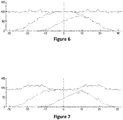
- the figure 6 represents a graph of a transverse distribution for which the flow and velocity parameters comply with those which allowed the reference measurements.
- the abscissa corresponds to the distance from the axis of the passage (m) and the ordinate to the quantity spread (%).
- the figure 7 is a graph of a cross-sectional distribution showing the impact of an increase in speed.
- the abscissa corresponds to the distance from the axis of the passage (m) and the ordinate to the quantity spread (%).
- the spreading speed generates the addition of an additional speed to the speed vectors of the particles leaving the disc.
- the effect on the web is uneven depending on the angle relative to the advancement of the spreader. This results in a modification of the landing places of the particles of product on the ground and generates a distortion of the slick formed on the ground and consequently by a modification of the transverse distribution of the rate of product and therefore of the final homogeneity of the soil. distribution (CV).
- the present invention makes it possible to improve the transverse distribution of a level of product.
- the method corrects said distortion.
- d ⁇ NPFopt ⁇ ⁇ NPFopt ⁇ D v . dD v + ⁇ ⁇ NPFopt ⁇ V . dV / Lw , Dose , Product , Disk , TPM Disc , ...
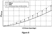
- the graph of the figure 8 schematically illustrates (unrealistic curve shapes) the contribution of our correction (Speed Control brick) in parallel to a DPA or DPAE.
- the speed control brick corrects the distortion effect due to the spreading speed and its impact on ballistic trajectories in the air (ballistic flight phase).
- the actuators of the spreader on which the corrections are made make it possible to correct a distortion of the spreading layer to return to an ideal RT minimizing the CV at the targeted Lw.
- the invention relates to a method 100 for compensating for the effect of the speed of movement of a centrifugal sprayer mounted on a vehicle on the quality of the transverse distribution of the spray.
- centrifugal spreader comprises two discs, which is generally the case. Nevertheless, the invention can be applied to any number of discs that it rotates in one direction or another.
- At least one actuator is caused to be adjusted during the process 100, individually or in parallel.
- the cross-sectional distribution quality is judged by zero difference between the shape of the actual cross-sectional distribution and that of the target cross-sectional distribution.
- the forms of transverse distributions are considered after adding the contributions of the quantities of particles by the successive passages in the plot and laterally shifted by the value of the working width, most often for example the forms of transverse distribution corresponding to a horizontal straight line. set to the value 100% of the overall quantity of particles actually distributed.
- a set of charts is produced, said charts making it possible to determine the correction to be made to at least one actuator to correct the effect of distortion of the spreading layer as a function of the speed of movement V of the vehicle.
- the charts obtained also depend on the nature of the product and the type of centrifugal spreader. Knowledge of these data and of the geometry on the ground then makes it possible to determine, for the target working width, the shape of the associated transverse distribution.
- the shape of the transverse distribution can be modeled according to the working width and the ballistic ability of the product to be spread.
- the correction of the speed effect to be made can thus be determined, in the case of a correction made by action on a single actuating member, using the abacus corresponding to said member and produced during the initial step.
- actuating members can be adjusted one after the other, according to the charts corresponding to each of the actuating members, until the desired correction is obtained.
- the correction to be made is determined by resorting to modeling and / or simulations, carried out in real time or a priori.
- the result of the modeling and / or simulation may be a vector of size M x 1 where M is the number of actuators likely to be individually modified as part of the correction.
- M is the number of actuators likely to be individually modified as part of the correction.
- the coefficients of this vector indicate the correction to be made to one or the other of the actuators to compensate for the effect of the speed.
- the vector obtained therefore depends on the speed V of the vehicle.
- the result of the modeling and / or simulation can be a square matrix C of size M x M where M is the number of actuators liable to be modified individually, or in parallel, as part of the correction.
- results of the modeling and / or simulation can be in a form other than matrix.
- the determination of the correction can also be performed by combining the first and second embodiments.
- the correction made to the actuators is made in real time, during spreading, and as a function of the actual displacement speed V measured during the measuring step 120.
- the compensation is considered in real time during spreading and adapted to the real speed in each position of the spreader.
- the figure 10 represents a software brick 10 according to the invention placed in parallel with a software system 11 of the DPA type (Flow rate proportional to the progress) or DPAE (Flow rate proportional to the electronic progress).
- DPA Flow rate proportional to the progress
- DPAE Flow rate proportional to the electronic progress
- the software system 11 processes this input data to determine a rate D of supplying the product to the rotating discs.
- the input data is also sent to the software brick 10, it is a question of determining the correction of a speed effect from the working width, the type of particles and for example the type of. disk.
- parameters of a disk can be processed independently of each other, or in combination.
- the data presented below are example values for certain corrections which were obtained with a working width of 32m for distributions of particles on the ground by the two discs located on average 17.5m from the axis of the discs. and at + -10 ° on either side of the spreader advancement axis (the reference axis being the longitudinal advance line of the centrifugal spreader starting from the centrifugal spreader and oriented towards the rear of the centrifugal spreader).
- the offset correction k 0 the corrections presented remain valid for spreading configurations of the same fertilizer (same average projection range of 17.5m) over widths ranging from 28m (average angle of 0 °, i.e. ie distribution centered on the feed line) at 36m (average angle of + -20 ° on either side of the feed line).
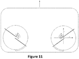
- the figure 11 shows a diagram of two rotating discs of the centrifugal spreader.
- the arrow around the discs shows their direction of rotation.
- Each disc shows two blades.
- the arrow near the deposit points corresponds to the increasing direction of the angular correction of the point of deposit of the particles on each disc.
- the arrow at the top of the rectangle represents the direction of movement of the centrifugal spreader.
- the spreader is fitted with two counter-rotating discs known as divergent rotation (the two discs distribute the particles from the center of the device to the outside). It would be the same for a spreader with counter-rotating discs with converging rotation.
- the feed zone can move in a rotary manner around the axis of rotation of the disc but also around an axis other than that of the center of the disc.
- the increasing direction of the angular correction of this zone of fall of the particles on the disc is the clockwise direction, whereas it is the counterclockwise for a left disc.
- This drop point can also move along the X and Y axes, the latter being for X aligned with the axis perpendicular to the direction of movement of the spreader (increasing in the direction from left to right of the spreader for a right disc), and for Y longitudinal to this same axis (increasing according to the direction of displacement).
- the figure 12 shows an example of an angular correction curve with a first degree equation.
- k 0 is defined by the passage through 0 for the displacement speed value V equal to 10 km / h.
- the constant k 1 is between 0.15 and 0.6.
- the constant k 1 is between -0.5 and -0.1.
- the figure 13 shows an example of a disc rotation speed correction curve with a first degree equation.
- the left ordinate corresponds to the correction in ⁇ and the right ordinate corresponds to the speed of rotation of the disk ⁇ .
- the figure 14 shows a diagram which shows the adjustment of the longitudinal inclination of the device or of the discs according to an exemplary embodiment with a wheel which is placed on the ground.
- the tractor represented by its wheel, has a coupling of the centrifugal spreader.
- an arrow on the right indicates the direction of travel.
- a negative tilt correction angle causes a "drop" of the spreader towards the rear depending on the direction of advance of the spreader.
- a positive angle of correction of the tilt of the centrifugal spreader is obtained mechanically by shortening (negative direction) of the highest coupling arm of the spreader on the tractor (shown in part in dotted lines and with an arrow).
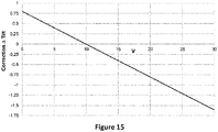
- the figure 15 shows an example of a centrifugal spreader or disc tilt correction adjustment curve with a first degree equation.
- the figure 16 shows an example of checking the implementation and proper functioning of the method.
- This control can be carried out without bringing the spreader into a plot, including without the possibility of connection to a GPS or means of measuring external climatic conditions. It is necessary to have technical means allowing simulation and sending to the control console of the spreader to note the information necessary for operation such as speed, target dose, target working width and flow rate.
- the following detection logic diagram is an example for a solution implementing a chute. It is possible to translate in the same way all the other approaches acting on the speed effect (disc speed, "Tilt”, angular position of the feed point, ⁇ )
- Step 200 represents the configuration step for the chute: the spreader is placed in spreading configuration, set for an initial working width, a dose (expressed for example in kg / ha), and a working speed .
- the width adjustment (the position of the chute for our example) adopted for these initial adjustments is recorded either on the electronics or the computer of the spreader, or directly on the actuators of the spreader (position of the chute in our example).
- Step 201 consists in modifying the target dose: Multiplication of the dose by 2 for example (the other parameters, including the speed, are kept fixed).
- Step 202 consists in identifying the possible consequences of this modification of the target dose on the working width adjustment member, the adjustment position of the chute in our example. If there has been an action, we go to step 203, otherwise we go to step 208.
- step 203 the control electronics of the spreader implements a control intended to correct the flow effect induced by the modification caused by the modification of the target dose on the flow rate and therefore on the quantity of granules d. fertilizer accelerated by each blade.
- Step 204 consists of returning to the initial dose (corresponding to the dose of step 200), then modifying the working speed by a factor of 2 (the other parameters being kept fixed).
- the flow rate (expressed for example in kg / min) is brought back to the same value as that following step 201.
- Step 205 therefore consists of looking at whether the modification of the position of the working width management member, the chute in our example, is the same value as that observed after step 201. If the answer is yes , we go to step 206, if the answer is no, we go to step 207.
- step 206 it is noted that the method has not been implemented, since the change of speed generating the same flow rate has not had an effect distinct from the step of 201 (there is no no correction of the speed effect, but only of the flow effect).
- step 207 the method of the invention is implemented, because the modification of the working speed has generated an action complementary to the compensation for the flow effect on the RT, directly correcting the speed effect. .
- step 208 it is deduced that the control electronics of the spreader is not provided with a control intended to correct the flow effect, and that this correction of the flow effect is provided by another way.
- Step 209 consists in modifying the working speed (the other parameters are kept fixed).
- Step 210 consists in looking to see if there has been a modification of the adjustment position of the member for managing the working width, the chute in our example. If the answer is yes, we go to step 211, if the answer is no, we go to step 212.
- step 211 it is observed that the method of the invention is implemented, the speed effect being taken into account, because the modification of the working speed has generated an action on the independent width adjustment. of the flow effect.
- step 212 it is noted that the method of the invention is not implemented, the speed effect is not taken into account.
- any multiplying factor other than 2 can be used.
- the dotted line in the diagram shows where the stage of the process relating to the correction of a speed effect is located.
- the speed effect (the distortion generated on the spatial distribution of ground particles induced by the speed) is determined, in order to act on the width adjustment (R_Lw3). This aspect takes into account the actual speed, as well as the characteristics of the product to be spread.
- the adjustment of the working width could be carried out in just one or two operations, using suitable equations taking into account the different parameters.
- the adjustment relating to the flow rate effect may in certain embodiments not be implemented in the form of a calculation, but using known suitable means.
- the curve resulting from these adjustments illustrates the objective of maintaining constant the transverse distribution of a particle rate, by taking into account on the one hand the flow effect, and on the other hand and in addition the speed effect (independently flow).
Landscapes
- Life Sciences & Earth Sciences (AREA)
- Soil Sciences (AREA)
- Environmental Sciences (AREA)
- Catching Or Destruction (AREA)
- Sowing (AREA)
- Fertilizing (AREA)
Applications Claiming Priority (1)
| Application Number | Priority Date | Filing Date | Title |
|---|---|---|---|
| FR2003622A FR3109054B1 (fr) | 2020-04-10 | 2020-04-10 | Procédé de réglage d’un épandeur centrifuge de particules et épandeur centrifuge de particules |
Publications (3)
| Publication Number | Publication Date |
|---|---|
| EP3892079A1 true EP3892079A1 (de) | 2021-10-13 |
| EP3892079B1 EP3892079B1 (de) | 2024-02-28 |
| EP3892079B8 EP3892079B8 (de) | 2024-06-12 |
Family
ID=70918668
Family Applications (1)
| Application Number | Title | Priority Date | Filing Date |
|---|---|---|---|
| EP21167920.4A Active EP3892079B8 (de) | 2020-04-10 | 2021-04-12 | Verfahren zur einstellung eines schleuderstreuers und entsprechender schleuderstreuer |
Country Status (4)
| Country | Link |
|---|---|
| EP (1) | EP3892079B8 (de) |
| BR (1) | BR102021006845A2 (de) |
| DK (1) | DK3892079T3 (de) |
| FR (1) | FR3109054B1 (de) |
Citations (7)
| Publication number | Priority date | Publication date | Assignee | Title |
|---|---|---|---|---|
| EP0472855A1 (de) | 1990-08-25 | 1992-03-04 | Rauch Landmaschinenfabrik GmbH | Verfahren zur Eichung eines Düngerstreuers |
| EP1707042A1 (de) | 2005-04-02 | 2006-10-04 | Rauch Landmaschinenfabrik Gmbh | Zweischeibenstreuer für Streugut, insbesondere Dünger, Salz oder dergleichen |
| EP2200420A1 (de) | 2007-10-04 | 2010-06-30 | David Stanley Hoyle | Streuer mit gps-geführtem streubild |
| EP2454928A1 (de) | 2010-11-18 | 2012-05-23 | Sulky Burel | Streuwerk mit Rutsche, das ermöglicht, den Durchsatzeffekt zu berücksichtigen |
| EP2556738A1 (de) * | 2011-08-12 | 2013-02-13 | Amazonen-Werke H. Dreyer GmbH & Co. KG | Verfahren zur Steuerung eines Zentrifugaldüngerstreuers |
| EP2868183A1 (de) | 2013-10-30 | 2015-05-06 | Amazonen-Werke H. Dreyer GmbH & Co. KG | Verfahren zum Verteilen von Mineraldünger |
| EP3305056A1 (de) * | 2016-10-05 | 2018-04-11 | RAUCH Landmaschinenfabrik GmbH | Verfahren zum gleichmässigen verteilen von streugut an lagen mit verschiedener bodenneigung mittels eines scheibenstreuers und hierfür geeigneter scheibenstreuer |
-
2020
- 2020-04-10 FR FR2003622A patent/FR3109054B1/fr active Active
-
2021
- 2021-04-09 BR BR102021006845-0A patent/BR102021006845A2/pt unknown
- 2021-04-12 DK DK21167920.4T patent/DK3892079T3/da active
- 2021-04-12 EP EP21167920.4A patent/EP3892079B8/de active Active
Patent Citations (7)
| Publication number | Priority date | Publication date | Assignee | Title |
|---|---|---|---|---|
| EP0472855A1 (de) | 1990-08-25 | 1992-03-04 | Rauch Landmaschinenfabrik GmbH | Verfahren zur Eichung eines Düngerstreuers |
| EP1707042A1 (de) | 2005-04-02 | 2006-10-04 | Rauch Landmaschinenfabrik Gmbh | Zweischeibenstreuer für Streugut, insbesondere Dünger, Salz oder dergleichen |
| EP2200420A1 (de) | 2007-10-04 | 2010-06-30 | David Stanley Hoyle | Streuer mit gps-geführtem streubild |
| EP2454928A1 (de) | 2010-11-18 | 2012-05-23 | Sulky Burel | Streuwerk mit Rutsche, das ermöglicht, den Durchsatzeffekt zu berücksichtigen |
| EP2556738A1 (de) * | 2011-08-12 | 2013-02-13 | Amazonen-Werke H. Dreyer GmbH & Co. KG | Verfahren zur Steuerung eines Zentrifugaldüngerstreuers |
| EP2868183A1 (de) | 2013-10-30 | 2015-05-06 | Amazonen-Werke H. Dreyer GmbH & Co. KG | Verfahren zum Verteilen von Mineraldünger |
| EP3305056A1 (de) * | 2016-10-05 | 2018-04-11 | RAUCH Landmaschinenfabrik GmbH | Verfahren zum gleichmässigen verteilen von streugut an lagen mit verschiedener bodenneigung mittels eines scheibenstreuers und hierfür geeigneter scheibenstreuer |
Also Published As
| Publication number | Publication date |
|---|---|
| FR3109054A1 (fr) | 2021-10-15 |
| DK3892079T3 (da) | 2024-04-15 |
| FR3109054B1 (fr) | 2022-08-26 |
| BR102021006845A2 (pt) | 2022-03-03 |
| EP3892079B1 (de) | 2024-02-28 |
| EP3892079B8 (de) | 2024-06-12 |
Similar Documents
| Publication | Publication Date | Title |
|---|---|---|
| EP3603369B1 (de) | Erfassung des durchflusses und steuerung einer fluidgabe unter verwendung einer landwirtschaftlichen maschine mit reihendrucksensoren | |
| US12419231B2 (en) | Sensing and control of liquid application using an agricultural machine | |
| EP3585168B1 (de) | Steuerungssystem für landwirtschaftliche feldspritzen | |
| EP2605643B1 (de) | Vorrichtung und verfahren zur ausgabe eines flüssigprodukts zum sprühen auf eine oberfläche | |
| CA3110431C (en) | Systems, methods and apparatus for multi-row agricultural implement control and monitoring | |
| EP3850397B1 (de) | Verfahren zur strassenerkennung für ein mit einem lidarsensor ausgestattetes kraftfahrzeug | |
| EP2560187B1 (de) | Verfahren zur Korrektur des elektronischen Proximity-Effekts durch Verwendung nicht-zentrierter Diffusionsfunktionen | |
| EP3765818B1 (de) | Verfahren zur kalibrierung eines in einem fahrzeug eingebauten gyrometers | |
| EP1976367B2 (de) | Bodenbearbeitungsmaschine in der art eines vertikalscheibenpfluges | |
| EP3892079B1 (de) | Verfahren zur einstellung eines schleuderstreuers und entsprechender schleuderstreuer | |
| EP0682857B1 (de) | Verfahren um die Streubreite für einen Granulatstreuer zu regeln | |
| FR2926437A1 (fr) | Procede de reglage d'une machine agricole d'epandage de particules, dispositif de reglage, machine agricole d'epandage et programme d'ordinateur correspondants | |
| Kweon et al. | Feed gate adaptation of a spinner spreader for uniformity control | |
| EP2798929A1 (de) | Verfahren zur automatischen Parametrisierung einer Kontrollvorrichtung für Arbeitsvorgänge einer Landmaschine, entsprechendes Computerprogramm, entsprechende Steuereinheit und entsprechende landwirtschaftliche Maschine | |
| FR2882496A1 (fr) | Procede d'optimisation et d'ajustement de l'epandage, machine d'epandage et programme d'ordinateur correspondants. | |
| EP1695606A1 (de) | Verfahren zur Optimierung und Einstellung des Streuens, zugehörige Streuer und Computerprogramm | |
| EP3884754B1 (de) | Vorrichtung zum verteilen von partikeln mit rotierenden scheiben, die den dosiseffekt bei niedrigen durchflussmengen ausgleicht | |
| FR2846190A1 (fr) | Epandeur centrifuge d'engrais | |
| EP4620285A1 (de) | Dosiervorrichtung für ein partikelabgabesystem für eine landwirtschaftliche maschine, entsprechendes dosierverfahren und landwirtschaftliche maschine. | |
| EP4681533A1 (de) | Verfahren zur steuerung des luftstroms für ein sprühgeràt | |
| US11991951B2 (en) | Agricultural seed loading mechanism for a belted conveyor | |
| FR3142327A1 (fr) | Systeme de pulverisation d’un produit pour engin agricole et procede associe | |
| CA3224867A1 (en) | CLOSED-LOOP SYSTEM CONTROL | |
| CA3219361A1 (en) | Machine control based on measured soil strength | |
| EP2705751A1 (de) | Automatisches Verfahren zur Bestimmung eines Modellerstellungsparameters eines Streuungssystems, Steuerverfahren und Streuungssystem, die einen solche Parameter verwenden |
Legal Events
| Date | Code | Title | Description |
|---|---|---|---|
| PUAI | Public reference made under article 153(3) epc to a published international application that has entered the european phase |
Free format text: ORIGINAL CODE: 0009012 |
|
| STAA | Information on the status of an ep patent application or granted ep patent |
Free format text: STATUS: THE APPLICATION HAS BEEN PUBLISHED |
|
| AK | Designated contracting states |
Kind code of ref document: A1 Designated state(s): AL AT BE BG CH CY CZ DE DK EE ES FI FR GB GR HR HU IE IS IT LI LT LU LV MC MK MT NL NO PL PT RO RS SE SI SK SM TR |
|
| STAA | Information on the status of an ep patent application or granted ep patent |
Free format text: STATUS: REQUEST FOR EXAMINATION WAS MADE |
|
| 17P | Request for examination filed |
Effective date: 20211230 |
|
| RBV | Designated contracting states (corrected) |
Designated state(s): AL AT BE BG CH CY CZ DE DK EE ES FI FR GB GR HR HU IE IS IT LI LT LU LV MC MK MT NL NO PL PT RO RS SE SI SK SM TR |
|
| GRAP | Despatch of communication of intention to grant a patent |
Free format text: ORIGINAL CODE: EPIDOSNIGR1 |
|
| STAA | Information on the status of an ep patent application or granted ep patent |
Free format text: STATUS: GRANT OF PATENT IS INTENDED |
|
| INTG | Intention to grant announced |
Effective date: 20230914 |
|
| GRAS | Grant fee paid |
Free format text: ORIGINAL CODE: EPIDOSNIGR3 |
|
| GRAA | (expected) grant |
Free format text: ORIGINAL CODE: 0009210 |
|
| STAA | Information on the status of an ep patent application or granted ep patent |
Free format text: STATUS: THE PATENT HAS BEEN GRANTED |
|
| AK | Designated contracting states |
Kind code of ref document: B1 Designated state(s): AL AT BE BG CH CY CZ DE DK EE ES FI FR GB GR HR HU IE IS IT LI LT LU LV MC MK MT NL NO PL PT RO RS SE SI SK SM TR |
|
| P01 | Opt-out of the competence of the unified patent court (upc) registered |
Effective date: 20240122 |
|
| REG | Reference to a national code |
Ref country code: GB Ref legal event code: FG4D Free format text: NOT ENGLISH |
|
| REG | Reference to a national code |
Ref country code: CH Ref legal event code: EP |
|
| REG | Reference to a national code |
Ref country code: DE Ref legal event code: R096 Ref document number: 602021009724 Country of ref document: DE |
|
| REG | Reference to a national code |
Ref country code: IE Ref legal event code: FG4D Free format text: LANGUAGE OF EP DOCUMENT: FRENCH |
|
| REG | Reference to a national code |
Ref country code: DK Ref legal event code: T3 Effective date: 20240409 |
|
| REG | Reference to a national code |
Ref country code: DE Ref legal event code: R081 Ref document number: 602021009724 Country of ref document: DE Owner name: INSTITUT NATIONAL DE RECHERCHE POUR L'AGRICULT, FR Free format text: FORMER OWNERS: INSTITUT NATIONAL DE RECHERCHE POUR L'AGRICULTURE, L'ALIMENTATION ET L'ENVIRONNEMENT, PARIS, FR; INSTITUT NATIONAL SUPERIEUR DES SCIENCES AGRONOMIQUES, DE L'ALIMENTATION ET DE L'ENVIRONNEMENT, DIJON, FR Ref country code: DE Ref legal event code: R081 Ref document number: 602021009724 Country of ref document: DE Owner name: INSTITUT NATIONAL D'ENSEIGNEMENT SUPERIEUR POU, FR Free format text: FORMER OWNERS: INSTITUT NATIONAL DE RECHERCHE POUR L'AGRICULTURE, L'ALIMENTATION ET L'ENVIRONNEMENT, PARIS, FR; INSTITUT NATIONAL SUPERIEUR DES SCIENCES AGRONOMIQUES, DE L'ALIMENTATION ET DE L'ENVIRONNEMENT, DIJON, FR |
|
| REG | Reference to a national code |
Ref country code: CH Ref legal event code: PK Free format text: RECTIFICATION B8 |
|
| RAP2 | Party data changed (patent owner data changed or rights of a patent transferred) |
Owner name: INSTITUT NATIONAL D'ENSEIGNEMENT SUPERIEUR POUR L'AGRICULTURE, L'ALIMENTATION ET L'ENVIRONNEMENT Owner name: INSTITUT NATIONAL DE RECHERCHE POUR L'AGRICULTURE, L'ALIMENTATION ET L'ENVIRONNEMENT |
|
| REG | Reference to a national code |
Ref country code: NL Ref legal event code: FP |
|
| REG | Reference to a national code |
Ref country code: LT Ref legal event code: MG9D |
|
| PG25 | Lapsed in a contracting state [announced via postgrant information from national office to epo] |
Ref country code: IS Free format text: LAPSE BECAUSE OF FAILURE TO SUBMIT A TRANSLATION OF THE DESCRIPTION OR TO PAY THE FEE WITHIN THE PRESCRIBED TIME-LIMIT Effective date: 20240628 |
|
| PG25 | Lapsed in a contracting state [announced via postgrant information from national office to epo] |
Ref country code: LT Free format text: LAPSE BECAUSE OF FAILURE TO SUBMIT A TRANSLATION OF THE DESCRIPTION OR TO PAY THE FEE WITHIN THE PRESCRIBED TIME-LIMIT Effective date: 20240228 |
|
| PG25 | Lapsed in a contracting state [announced via postgrant information from national office to epo] |
Ref country code: GR Free format text: LAPSE BECAUSE OF FAILURE TO SUBMIT A TRANSLATION OF THE DESCRIPTION OR TO PAY THE FEE WITHIN THE PRESCRIBED TIME-LIMIT Effective date: 20240529 |
|
| PG25 | Lapsed in a contracting state [announced via postgrant information from national office to epo] |
Ref country code: RS Free format text: LAPSE BECAUSE OF FAILURE TO SUBMIT A TRANSLATION OF THE DESCRIPTION OR TO PAY THE FEE WITHIN THE PRESCRIBED TIME-LIMIT Effective date: 20240528 Ref country code: HR Free format text: LAPSE BECAUSE OF FAILURE TO SUBMIT A TRANSLATION OF THE DESCRIPTION OR TO PAY THE FEE WITHIN THE PRESCRIBED TIME-LIMIT Effective date: 20240228 |
|
| PG25 | Lapsed in a contracting state [announced via postgrant information from national office to epo] |
Ref country code: ES Free format text: LAPSE BECAUSE OF FAILURE TO SUBMIT A TRANSLATION OF THE DESCRIPTION OR TO PAY THE FEE WITHIN THE PRESCRIBED TIME-LIMIT Effective date: 20240228 |
|
| PG25 | Lapsed in a contracting state [announced via postgrant information from national office to epo] |
Ref country code: RS Free format text: LAPSE BECAUSE OF FAILURE TO SUBMIT A TRANSLATION OF THE DESCRIPTION OR TO PAY THE FEE WITHIN THE PRESCRIBED TIME-LIMIT Effective date: 20240528 Ref country code: NO Free format text: LAPSE BECAUSE OF FAILURE TO SUBMIT A TRANSLATION OF THE DESCRIPTION OR TO PAY THE FEE WITHIN THE PRESCRIBED TIME-LIMIT Effective date: 20240528 Ref country code: LT Free format text: LAPSE BECAUSE OF FAILURE TO SUBMIT A TRANSLATION OF THE DESCRIPTION OR TO PAY THE FEE WITHIN THE PRESCRIBED TIME-LIMIT Effective date: 20240228 Ref country code: IS Free format text: LAPSE BECAUSE OF FAILURE TO SUBMIT A TRANSLATION OF THE DESCRIPTION OR TO PAY THE FEE WITHIN THE PRESCRIBED TIME-LIMIT Effective date: 20240628 Ref country code: HR Free format text: LAPSE BECAUSE OF FAILURE TO SUBMIT A TRANSLATION OF THE DESCRIPTION OR TO PAY THE FEE WITHIN THE PRESCRIBED TIME-LIMIT Effective date: 20240228 Ref country code: GR Free format text: LAPSE BECAUSE OF FAILURE TO SUBMIT A TRANSLATION OF THE DESCRIPTION OR TO PAY THE FEE WITHIN THE PRESCRIBED TIME-LIMIT Effective date: 20240529 Ref country code: FI Free format text: LAPSE BECAUSE OF FAILURE TO SUBMIT A TRANSLATION OF THE DESCRIPTION OR TO PAY THE FEE WITHIN THE PRESCRIBED TIME-LIMIT Effective date: 20240228 Ref country code: ES Free format text: LAPSE BECAUSE OF FAILURE TO SUBMIT A TRANSLATION OF THE DESCRIPTION OR TO PAY THE FEE WITHIN THE PRESCRIBED TIME-LIMIT Effective date: 20240228 Ref country code: BG Free format text: LAPSE BECAUSE OF FAILURE TO SUBMIT A TRANSLATION OF THE DESCRIPTION OR TO PAY THE FEE WITHIN THE PRESCRIBED TIME-LIMIT Effective date: 20240228 |
|
| PG25 | Lapsed in a contracting state [announced via postgrant information from national office to epo] |
Ref country code: PT Free format text: LAPSE BECAUSE OF FAILURE TO SUBMIT A TRANSLATION OF THE DESCRIPTION OR TO PAY THE FEE WITHIN THE PRESCRIBED TIME-LIMIT Effective date: 20240628 Ref country code: PL Free format text: LAPSE BECAUSE OF FAILURE TO SUBMIT A TRANSLATION OF THE DESCRIPTION OR TO PAY THE FEE WITHIN THE PRESCRIBED TIME-LIMIT Effective date: 20240228 |
|
| REG | Reference to a national code |
Ref country code: AT Ref legal event code: MK05 Ref document number: 1660273 Country of ref document: AT Kind code of ref document: T Effective date: 20240228 |
|
| PG25 | Lapsed in a contracting state [announced via postgrant information from national office to epo] |
Ref country code: SE Free format text: LAPSE BECAUSE OF FAILURE TO SUBMIT A TRANSLATION OF THE DESCRIPTION OR TO PAY THE FEE WITHIN THE PRESCRIBED TIME-LIMIT Effective date: 20240228 Ref country code: PT Free format text: LAPSE BECAUSE OF FAILURE TO SUBMIT A TRANSLATION OF THE DESCRIPTION OR TO PAY THE FEE WITHIN THE PRESCRIBED TIME-LIMIT Effective date: 20240628 Ref country code: PL Free format text: LAPSE BECAUSE OF FAILURE TO SUBMIT A TRANSLATION OF THE DESCRIPTION OR TO PAY THE FEE WITHIN THE PRESCRIBED TIME-LIMIT Effective date: 20240228 Ref country code: LV Free format text: LAPSE BECAUSE OF FAILURE TO SUBMIT A TRANSLATION OF THE DESCRIPTION OR TO PAY THE FEE WITHIN THE PRESCRIBED TIME-LIMIT Effective date: 20240228 |
|
| PG25 | Lapsed in a contracting state [announced via postgrant information from national office to epo] |
Ref country code: SM Free format text: LAPSE BECAUSE OF FAILURE TO SUBMIT A TRANSLATION OF THE DESCRIPTION OR TO PAY THE FEE WITHIN THE PRESCRIBED TIME-LIMIT Effective date: 20240228 |
|
| PG25 | Lapsed in a contracting state [announced via postgrant information from national office to epo] |
Ref country code: EE Free format text: LAPSE BECAUSE OF FAILURE TO SUBMIT A TRANSLATION OF THE DESCRIPTION OR TO PAY THE FEE WITHIN THE PRESCRIBED TIME-LIMIT Effective date: 20240228 Ref country code: CZ Free format text: LAPSE BECAUSE OF FAILURE TO SUBMIT A TRANSLATION OF THE DESCRIPTION OR TO PAY THE FEE WITHIN THE PRESCRIBED TIME-LIMIT Effective date: 20240228 |
|
| PG25 | Lapsed in a contracting state [announced via postgrant information from national office to epo] |
Ref country code: AT Free format text: LAPSE BECAUSE OF FAILURE TO SUBMIT A TRANSLATION OF THE DESCRIPTION OR TO PAY THE FEE WITHIN THE PRESCRIBED TIME-LIMIT Effective date: 20240228 |
|
| PG25 | Lapsed in a contracting state [announced via postgrant information from national office to epo] |
Ref country code: SK Free format text: LAPSE BECAUSE OF FAILURE TO SUBMIT A TRANSLATION OF THE DESCRIPTION OR TO PAY THE FEE WITHIN THE PRESCRIBED TIME-LIMIT Effective date: 20240228 |
|
| PG25 | Lapsed in a contracting state [announced via postgrant information from national office to epo] |
Ref country code: SM Free format text: LAPSE BECAUSE OF FAILURE TO SUBMIT A TRANSLATION OF THE DESCRIPTION OR TO PAY THE FEE WITHIN THE PRESCRIBED TIME-LIMIT Effective date: 20240228 Ref country code: SK Free format text: LAPSE BECAUSE OF FAILURE TO SUBMIT A TRANSLATION OF THE DESCRIPTION OR TO PAY THE FEE WITHIN THE PRESCRIBED TIME-LIMIT Effective date: 20240228 Ref country code: RO Free format text: LAPSE BECAUSE OF FAILURE TO SUBMIT A TRANSLATION OF THE DESCRIPTION OR TO PAY THE FEE WITHIN THE PRESCRIBED TIME-LIMIT Effective date: 20240228 Ref country code: EE Free format text: LAPSE BECAUSE OF FAILURE TO SUBMIT A TRANSLATION OF THE DESCRIPTION OR TO PAY THE FEE WITHIN THE PRESCRIBED TIME-LIMIT Effective date: 20240228 Ref country code: CZ Free format text: LAPSE BECAUSE OF FAILURE TO SUBMIT A TRANSLATION OF THE DESCRIPTION OR TO PAY THE FEE WITHIN THE PRESCRIBED TIME-LIMIT Effective date: 20240228 Ref country code: AT Free format text: LAPSE BECAUSE OF FAILURE TO SUBMIT A TRANSLATION OF THE DESCRIPTION OR TO PAY THE FEE WITHIN THE PRESCRIBED TIME-LIMIT Effective date: 20240228 |
|
| PG25 | Lapsed in a contracting state [announced via postgrant information from national office to epo] |
Ref country code: MC Free format text: LAPSE BECAUSE OF FAILURE TO SUBMIT A TRANSLATION OF THE DESCRIPTION OR TO PAY THE FEE WITHIN THE PRESCRIBED TIME-LIMIT Effective date: 20240228 |
|
| PG25 | Lapsed in a contracting state [announced via postgrant information from national office to epo] |
Ref country code: MC Free format text: LAPSE BECAUSE OF FAILURE TO SUBMIT A TRANSLATION OF THE DESCRIPTION OR TO PAY THE FEE WITHIN THE PRESCRIBED TIME-LIMIT Effective date: 20240228 |
|
| REG | Reference to a national code |
Ref country code: DE Ref legal event code: R097 Ref document number: 602021009724 Country of ref document: DE Ref country code: CH Ref legal event code: PL |
|
| PG25 | Lapsed in a contracting state [announced via postgrant information from national office to epo] |
Ref country code: IT Free format text: LAPSE BECAUSE OF FAILURE TO SUBMIT A TRANSLATION OF THE DESCRIPTION OR TO PAY THE FEE WITHIN THE PRESCRIBED TIME-LIMIT Effective date: 20240228 |
|
| PG25 | Lapsed in a contracting state [announced via postgrant information from national office to epo] |
Ref country code: LU Free format text: LAPSE BECAUSE OF NON-PAYMENT OF DUE FEES Effective date: 20240412 |
|
| REG | Reference to a national code |
Ref country code: BE Ref legal event code: MM Effective date: 20240430 |
|
| PG25 | Lapsed in a contracting state [announced via postgrant information from national office to epo] |
Ref country code: LU Free format text: LAPSE BECAUSE OF NON-PAYMENT OF DUE FEES Effective date: 20240412 Ref country code: IT Free format text: LAPSE BECAUSE OF FAILURE TO SUBMIT A TRANSLATION OF THE DESCRIPTION OR TO PAY THE FEE WITHIN THE PRESCRIBED TIME-LIMIT Effective date: 20240228 |
|
| PLBE | No opposition filed within time limit |
Free format text: ORIGINAL CODE: 0009261 |
|
| STAA | Information on the status of an ep patent application or granted ep patent |
Free format text: STATUS: NO OPPOSITION FILED WITHIN TIME LIMIT |
|
| PG25 | Lapsed in a contracting state [announced via postgrant information from national office to epo] |
Ref country code: BE Free format text: LAPSE BECAUSE OF NON-PAYMENT OF DUE FEES Effective date: 20240430 |
|
| PG25 | Lapsed in a contracting state [announced via postgrant information from national office to epo] |
Ref country code: BE Free format text: LAPSE BECAUSE OF NON-PAYMENT OF DUE FEES Effective date: 20240430 Ref country code: CH Free format text: LAPSE BECAUSE OF NON-PAYMENT OF DUE FEES Effective date: 20240430 |
|
| 26N | No opposition filed |
Effective date: 20241129 |
|
| PG25 | Lapsed in a contracting state [announced via postgrant information from national office to epo] |
Ref country code: IE Free format text: LAPSE BECAUSE OF NON-PAYMENT OF DUE FEES Effective date: 20240412 |
|
| PG25 | Lapsed in a contracting state [announced via postgrant information from national office to epo] |
Ref country code: SI Free format text: LAPSE BECAUSE OF FAILURE TO SUBMIT A TRANSLATION OF THE DESCRIPTION OR TO PAY THE FEE WITHIN THE PRESCRIBED TIME-LIMIT Effective date: 20240228 |
|
| PGFP | Annual fee paid to national office [announced via postgrant information from national office to epo] |
Ref country code: NL Payment date: 20250423 Year of fee payment: 5 |
|
| PGFP | Annual fee paid to national office [announced via postgrant information from national office to epo] |
Ref country code: DE Payment date: 20250417 Year of fee payment: 5 |
|
| PGFP | Annual fee paid to national office [announced via postgrant information from national office to epo] |
Ref country code: DK Payment date: 20250423 Year of fee payment: 5 |
|
| PGFP | Annual fee paid to national office [announced via postgrant information from national office to epo] |
Ref country code: FR Payment date: 20250422 Year of fee payment: 5 |
|
| PG25 | Lapsed in a contracting state [announced via postgrant information from national office to epo] |
Ref country code: CY Free format text: LAPSE BECAUSE OF FAILURE TO SUBMIT A TRANSLATION OF THE DESCRIPTION OR TO PAY THE FEE WITHIN THE PRESCRIBED TIME-LIMIT; INVALID AB INITIO Effective date: 20210412 |
|
| PG25 | Lapsed in a contracting state [announced via postgrant information from national office to epo] |
Ref country code: HU Free format text: LAPSE BECAUSE OF FAILURE TO SUBMIT A TRANSLATION OF THE DESCRIPTION OR TO PAY THE FEE WITHIN THE PRESCRIBED TIME-LIMIT; INVALID AB INITIO Effective date: 20210412 |
|
| GBPC | Gb: european patent ceased through non-payment of renewal fee |
Effective date: 20250412 |
|
| PG25 | Lapsed in a contracting state [announced via postgrant information from national office to epo] |
Ref country code: GB Free format text: LAPSE BECAUSE OF NON-PAYMENT OF DUE FEES Effective date: 20250412 |