EP3892171B1 - Kochgerät - Google Patents
Kochgerät Download PDFInfo
- Publication number
- EP3892171B1 EP3892171B1 EP21167042.7A EP21167042A EP3892171B1 EP 3892171 B1 EP3892171 B1 EP 3892171B1 EP 21167042 A EP21167042 A EP 21167042A EP 3892171 B1 EP3892171 B1 EP 3892171B1
- Authority
- EP
- European Patent Office
- Prior art keywords
- cooking
- gas
- appliance
- electric
- chamber
- Prior art date
- Legal status (The legal status is an assumption and is not a legal conclusion. Google has not performed a legal analysis and makes no representation as to the accuracy of the status listed.)
- Active
Links
Images


Classifications
-
- A—HUMAN NECESSITIES
- A47—FURNITURE; DOMESTIC ARTICLES OR APPLIANCES; COFFEE MILLS; SPICE MILLS; SUCTION CLEANERS IN GENERAL
- A47J—KITCHEN EQUIPMENT; COFFEE MILLS; SPICE MILLS; APPARATUS FOR MAKING BEVERAGES
- A47J37/00—Baking; Roasting; Grilling; Frying
- A47J37/06—Roasters; Grills; Sandwich grills
-
- H—ELECTRICITY
- H05—ELECTRIC TECHNIQUES NOT OTHERWISE PROVIDED FOR
- H05B—ELECTRIC HEATING; ELECTRIC LIGHT SOURCES NOT OTHERWISE PROVIDED FOR; CIRCUIT ARRANGEMENTS FOR ELECTRIC LIGHT SOURCES, IN GENERAL
- H05B3/00—Ohmic-resistance heating
- H05B3/68—Heating arrangements specially adapted for cooking plates or analogous hot-plates
-
- A—HUMAN NECESSITIES
- A47—FURNITURE; DOMESTIC ARTICLES OR APPLIANCES; COFFEE MILLS; SPICE MILLS; SUCTION CLEANERS IN GENERAL
- A47J—KITCHEN EQUIPMENT; COFFEE MILLS; SPICE MILLS; APPARATUS FOR MAKING BEVERAGES
- A47J37/00—Baking; Roasting; Grilling; Frying
- A47J37/06—Roasters; Grills; Sandwich grills
- A47J37/0611—Roasters; Grills; Sandwich grills the food being cooked between two heating plates, e.g. waffle-irons
-
- A—HUMAN NECESSITIES
- A47—FURNITURE; DOMESTIC ARTICLES OR APPLIANCES; COFFEE MILLS; SPICE MILLS; SUCTION CLEANERS IN GENERAL
- A47J—KITCHEN EQUIPMENT; COFFEE MILLS; SPICE MILLS; APPARATUS FOR MAKING BEVERAGES
- A47J37/00—Baking; Roasting; Grilling; Frying
- A47J37/06—Roasters; Grills; Sandwich grills
- A47J37/0623—Small-size cooking ovens, i.e. defining an at least partially closed cooking cavity
- A47J37/0629—Small-size cooking ovens, i.e. defining an at least partially closed cooking cavity with electric heating elements
-
- A—HUMAN NECESSITIES
- A47—FURNITURE; DOMESTIC ARTICLES OR APPLIANCES; COFFEE MILLS; SPICE MILLS; SUCTION CLEANERS IN GENERAL
- A47J—KITCHEN EQUIPMENT; COFFEE MILLS; SPICE MILLS; APPARATUS FOR MAKING BEVERAGES
- A47J37/00—Baking; Roasting; Grilling; Frying
- A47J37/06—Roasters; Grills; Sandwich grills
- A47J37/0623—Small-size cooking ovens, i.e. defining an at least partially closed cooking cavity
- A47J37/0647—Small-size cooking ovens, i.e. defining an at least partially closed cooking cavity with gas burners
-
- A—HUMAN NECESSITIES
- A47—FURNITURE; DOMESTIC ARTICLES OR APPLIANCES; COFFEE MILLS; SPICE MILLS; SUCTION CLEANERS IN GENERAL
- A47J—KITCHEN EQUIPMENT; COFFEE MILLS; SPICE MILLS; APPARATUS FOR MAKING BEVERAGES
- A47J37/00—Baking; Roasting; Grilling; Frying
- A47J37/06—Roasters; Grills; Sandwich grills
- A47J37/0623—Small-size cooking ovens, i.e. defining an at least partially closed cooking cavity
- A47J37/0664—Accessories
-
- A—HUMAN NECESSITIES
- A47—FURNITURE; DOMESTIC ARTICLES OR APPLIANCES; COFFEE MILLS; SPICE MILLS; SUCTION CLEANERS IN GENERAL
- A47J—KITCHEN EQUIPMENT; COFFEE MILLS; SPICE MILLS; APPARATUS FOR MAKING BEVERAGES
- A47J37/00—Baking; Roasting; Grilling; Frying
- A47J37/06—Roasters; Grills; Sandwich grills
- A47J37/067—Horizontally disposed broiling griddles
- A47J37/0676—Horizontally disposed broiling griddles electrically heated
-
- A—HUMAN NECESSITIES
- A47—FURNITURE; DOMESTIC ARTICLES OR APPLIANCES; COFFEE MILLS; SPICE MILLS; SUCTION CLEANERS IN GENERAL
- A47J—KITCHEN EQUIPMENT; COFFEE MILLS; SPICE MILLS; APPARATUS FOR MAKING BEVERAGES
- A47J37/00—Baking; Roasting; Grilling; Frying
- A47J37/06—Roasters; Grills; Sandwich grills
- A47J37/067—Horizontally disposed broiling griddles
- A47J37/0682—Horizontally disposed broiling griddles gas-heated
-
- A—HUMAN NECESSITIES
- A47—FURNITURE; DOMESTIC ARTICLES OR APPLIANCES; COFFEE MILLS; SPICE MILLS; SUCTION CLEANERS IN GENERAL
- A47J—KITCHEN EQUIPMENT; COFFEE MILLS; SPICE MILLS; APPARATUS FOR MAKING BEVERAGES
- A47J37/00—Baking; Roasting; Grilling; Frying
- A47J37/06—Roasters; Grills; Sandwich grills
- A47J37/07—Roasting devices for outdoor use; Barbecues
- A47J37/0704—Roasting devices for outdoor use; Barbecues with horizontal fire box
- A47J37/0709—Roasting devices for outdoor use; Barbecues with horizontal fire box with electric heating elements
-
- A—HUMAN NECESSITIES
- A47—FURNITURE; DOMESTIC ARTICLES OR APPLIANCES; COFFEE MILLS; SPICE MILLS; SUCTION CLEANERS IN GENERAL
- A47J—KITCHEN EQUIPMENT; COFFEE MILLS; SPICE MILLS; APPARATUS FOR MAKING BEVERAGES
- A47J37/00—Baking; Roasting; Grilling; Frying
- A47J37/06—Roasters; Grills; Sandwich grills
- A47J37/07—Roasting devices for outdoor use; Barbecues
- A47J37/0704—Roasting devices for outdoor use; Barbecues with horizontal fire box
- A47J37/0713—Roasting devices for outdoor use; Barbecues with horizontal fire box with gas burners
-
- A—HUMAN NECESSITIES
- A47—FURNITURE; DOMESTIC ARTICLES OR APPLIANCES; COFFEE MILLS; SPICE MILLS; SUCTION CLEANERS IN GENERAL
- A47J—KITCHEN EQUIPMENT; COFFEE MILLS; SPICE MILLS; APPARATUS FOR MAKING BEVERAGES
- A47J37/00—Baking; Roasting; Grilling; Frying
- A47J37/06—Roasters; Grills; Sandwich grills
- A47J37/07—Roasting devices for outdoor use; Barbecues
- A47J37/0718—Roasting devices for outdoor use; Barbecues with vertical fire box
- A47J37/0722—Roasting devices for outdoor use; Barbecues with vertical fire box with electric heating elements
-
- A—HUMAN NECESSITIES
- A47—FURNITURE; DOMESTIC ARTICLES OR APPLIANCES; COFFEE MILLS; SPICE MILLS; SUCTION CLEANERS IN GENERAL
- A47J—KITCHEN EQUIPMENT; COFFEE MILLS; SPICE MILLS; APPARATUS FOR MAKING BEVERAGES
- A47J37/00—Baking; Roasting; Grilling; Frying
- A47J37/06—Roasters; Grills; Sandwich grills
- A47J37/07—Roasting devices for outdoor use; Barbecues
- A47J37/0718—Roasting devices for outdoor use; Barbecues with vertical fire box
- A47J37/0727—Roasting devices for outdoor use; Barbecues with vertical fire box with gas burners
-
- A—HUMAN NECESSITIES
- A47—FURNITURE; DOMESTIC ARTICLES OR APPLIANCES; COFFEE MILLS; SPICE MILLS; SUCTION CLEANERS IN GENERAL
- A47J—KITCHEN EQUIPMENT; COFFEE MILLS; SPICE MILLS; APPARATUS FOR MAKING BEVERAGES
- A47J37/00—Baking; Roasting; Grilling; Frying
- A47J37/06—Roasters; Grills; Sandwich grills
- A47J37/07—Roasting devices for outdoor use; Barbecues
- A47J37/0731—Roasting devices for outdoor use; Barbecues with a fire box movable between different positions, e.g. horizontal, vertical, inclined
- A47J37/0736—Roasting devices for outdoor use; Barbecues with a fire box movable between different positions, e.g. horizontal, vertical, inclined with electric heating elements
-
- A—HUMAN NECESSITIES
- A47—FURNITURE; DOMESTIC ARTICLES OR APPLIANCES; COFFEE MILLS; SPICE MILLS; SUCTION CLEANERS IN GENERAL
- A47J—KITCHEN EQUIPMENT; COFFEE MILLS; SPICE MILLS; APPARATUS FOR MAKING BEVERAGES
- A47J37/00—Baking; Roasting; Grilling; Frying
- A47J37/06—Roasters; Grills; Sandwich grills
- A47J37/07—Roasting devices for outdoor use; Barbecues
- A47J37/0731—Roasting devices for outdoor use; Barbecues with a fire box movable between different positions, e.g. horizontal, vertical, inclined
- A47J37/074—Roasting devices for outdoor use; Barbecues with a fire box movable between different positions, e.g. horizontal, vertical, inclined with gas burners
-
- A—HUMAN NECESSITIES
- A47—FURNITURE; DOMESTIC ARTICLES OR APPLIANCES; COFFEE MILLS; SPICE MILLS; SUCTION CLEANERS IN GENERAL
- A47J—KITCHEN EQUIPMENT; COFFEE MILLS; SPICE MILLS; APPARATUS FOR MAKING BEVERAGES
- A47J37/00—Baking; Roasting; Grilling; Frying
- A47J37/06—Roasters; Grills; Sandwich grills
- A47J37/07—Roasting devices for outdoor use; Barbecues
- A47J37/0754—Roasting devices for outdoor use; Barbecues with blowers providing forced air circulation
-
- A—HUMAN NECESSITIES
- A47—FURNITURE; DOMESTIC ARTICLES OR APPLIANCES; COFFEE MILLS; SPICE MILLS; SUCTION CLEANERS IN GENERAL
- A47J—KITCHEN EQUIPMENT; COFFEE MILLS; SPICE MILLS; APPARATUS FOR MAKING BEVERAGES
- A47J37/00—Baking; Roasting; Grilling; Frying
- A47J37/06—Roasters; Grills; Sandwich grills
- A47J37/07—Roasting devices for outdoor use; Barbecues
- A47J37/0786—Accessories
-
- F—MECHANICAL ENGINEERING; LIGHTING; HEATING; WEAPONS; BLASTING
- F24—HEATING; RANGES; VENTILATING
- F24C—DOMESTIC STOVES OR RANGES ; DETAILS OF DOMESTIC STOVES OR RANGES, OF GENERAL APPLICATION
- F24C1/00—Stoves or ranges in which the fuel or energy supply is not restricted to solid fuel or to a type covered by a single one of the following groups F24C3/00 - F24C9/00; Stoves or ranges in which the type of fuel or energy supply is not specified
- F24C1/02—Stoves or ranges in which the fuel or energy supply is not restricted to solid fuel or to a type covered by a single one of the following groups F24C3/00 - F24C9/00; Stoves or ranges in which the type of fuel or energy supply is not specified adapted for the use of two or more kinds of fuel or energy supply
-
- F—MECHANICAL ENGINEERING; LIGHTING; HEATING; WEAPONS; BLASTING
- F24—HEATING; RANGES; VENTILATING
- F24C—DOMESTIC STOVES OR RANGES ; DETAILS OF DOMESTIC STOVES OR RANGES, OF GENERAL APPLICATION
- F24C11/00—Combinations of two or more stoves or ranges, e.g. each having a different kind of energy supply
-
- H—ELECTRICITY
- H05—ELECTRIC TECHNIQUES NOT OTHERWISE PROVIDED FOR
- H05B—ELECTRIC HEATING; ELECTRIC LIGHT SOURCES NOT OTHERWISE PROVIDED FOR; CIRCUIT ARRANGEMENTS FOR ELECTRIC LIGHT SOURCES, IN GENERAL
- H05B3/00—Ohmic-resistance heating
- H05B3/40—Heating elements having the shape of rods or tubes
- H05B3/42—Heating elements having the shape of rods or tubes non-flexible
-
- H—ELECTRICITY
- H05—ELECTRIC TECHNIQUES NOT OTHERWISE PROVIDED FOR
- H05B—ELECTRIC HEATING; ELECTRIC LIGHT SOURCES NOT OTHERWISE PROVIDED FOR; CIRCUIT ARRANGEMENTS FOR ELECTRIC LIGHT SOURCES, IN GENERAL
- H05B3/00—Ohmic-resistance heating
- H05B3/68—Heating arrangements specially adapted for cooking plates or analogous hot-plates
- H05B3/681—Plates having mobile parts coming into contact with the bottom of the kettles, pans, or the like
-
- A—HUMAN NECESSITIES
- A47—FURNITURE; DOMESTIC ARTICLES OR APPLIANCES; COFFEE MILLS; SPICE MILLS; SUCTION CLEANERS IN GENERAL
- A47J—KITCHEN EQUIPMENT; COFFEE MILLS; SPICE MILLS; APPARATUS FOR MAKING BEVERAGES
- A47J2201/00—Devices having a modular construction
-
- A—HUMAN NECESSITIES
- A47—FURNITURE; DOMESTIC ARTICLES OR APPLIANCES; COFFEE MILLS; SPICE MILLS; SUCTION CLEANERS IN GENERAL
- A47J—KITCHEN EQUIPMENT; COFFEE MILLS; SPICE MILLS; APPARATUS FOR MAKING BEVERAGES
- A47J27/00—Cooking-vessels
- A47J27/12—Multiple-unit cooking vessels
-
- F—MECHANICAL ENGINEERING; LIGHTING; HEATING; WEAPONS; BLASTING
- F24—HEATING; RANGES; VENTILATING
- F24C—DOMESTIC STOVES OR RANGES ; DETAILS OF DOMESTIC STOVES OR RANGES, OF GENERAL APPLICATION
- F24C15/00—Details
- F24C15/12—Side rests; Side plates; Cover lids; Splash guards; Racks outside ovens, e.g. for drying plates
Definitions
- the invention relates to cooking appliances.
- Cooking appliances such as grills and barbeque cooking appliances are commonly used for cooking food.
- DE2516906 (COZZIO SEVERIN ) relates to an easily converted griller and fryer - having an indirectly heated hot plate resting on bottom plate for frying purposes.
- the combined frying and grilling apparatus comprises two hot plates which are mounted in movable holders, the upper hot plate which is heated indirectly by a heat radiation source, designed to engage on the upper holder acting as a contact grill in conjunction with the lower heated hot plate.
- a heat radiation source designed to engage on the upper holder acting as a contact grill in conjunction with the lower heated hot plate.
- On disengaging the upper hot plate from its holder it can be placed on the lower hot plate so that when raising the upper holder the heat radiation source for the upper plate serves as a mechanism for frying the food which is placed on the back of the upper hot plate.
- the heat radiation source for the upper hot plate preferably consists of gas pipes with several jets which serve as the burner and heat up the wire or metal mesh which faces the reverse side of the upper hot plate.
- the lower hot plate can be heated directly by a
- DE2709326 (MORITZ JEAN MARC ) relates to a combined outdoor cooker, grill and heater - having two housing hinged together, containing heat sources, fitted with adjusting frame.
- the combined cooker, grill and heating appliance is for outdoor use, and consists of two stands formed as housings, which are hinged to each other. Each housing has a heat source one of them having telescopic feet.
- the housings may be adjusted relative to each other by a frame.
- the housings may have a container, for cooking purposes and a grill plate, both being fastened via rapid connections. Opposite sides of the housings have recesses to hold a grate, for cooking.
- the adjustment frame consists of a U-shaped rod, with arms, fastened to it.
- DE202012006160U (MEIDER ALEXANDER ) relates to a Charcoal-electric combination grill.
- the charcoal-electric combi grill allows the user to heat with charcoal or electric, characterized in that the grill chamber contains features and elements of two different heating variants (charcoal and electric) through its construction. The detachability of all parts facilitates the use of each of the two heating variants.
- aspects disclosed herein relate to cooking appliances, such as barbeque cooking appliances and grills, which may be used outdoors and/or indoors. Some aspects relate to multi-fuel barbecue grill.
- Ribbing plus insulation of the cooking chamber and lid, are other techniques used in an effort to conserve as much energy as possible to allow optimization of the size of the cooking area.
- the char lines limit how many watts/BTU's are needed to get some char lines and flavor into the food, meat in particular. To char the meat over a wider area would take more power.
- Cooking appliances and grills such as barbeque cooking appliances and the like, are useable. These are normally gas or mains electric powered. They may have open slat grills or flat griddles or a mixture of both with electric radiant elements or open gas burners mounted below the grill plate to cook food placed above by radiation and convection. In some alterations, the elements, gas or electric, are placed above the grill plate and radiate energy down onto the food from above. Another different type sees the electric elements mounted vertically on each side of the food holder and radiate energy laterally.
- Another different type is the direct contact clamshell type grill (that are based loosely on toasted-sandwich grills) that cooks food from the top and bottom simultaneously, by virtue of generally an upper electrically heated lid mounted grill plate hingedly connected to a lower body with its own electrically heated plate.
- the plates are typically solid metal type, flat or ribbed, but rely mainly on heat conduction for cooking. Food (such as beef steak) is compressed between the heated lid plate and the heated bottom plate and is rapid seared and heated from both sides. This simultaneously seals two surfaces of the food and provides good cooking results.
- the clamshell type grill as described above may alternatively utilize open radiation type glowing electric elements and not heated platens.
- cooking appliances such as grills and barbeque cooking appliances
- gas heating tubes or elements powered either from large liquified gas bottles in the 0.5Kg to 10Kg to 100lb range, or from reticulated (e.g. natural) gas.
- reticulated gas e.g. natural gas.
- Some others are designed to also accept "disposable", small, pressurized cans of butane and/or propane, which are deemed to be safer in a building or vehicle than bulk supply cylinders and present less hazard if used indoors or in recreational vehicles in areas where regulations allow.
- cooking appliances may be heated by electric elements that are powered by mains 120-volt AC supply or mains 240-volt AC supply via a mains power cord.
- Some of these cooking appliances are "portable” in that they can be used at home or in caravans or when camping for instance. Some of them are intended to be used mainly at home and are on trolleys or leg sets and are movable.
- Some of these cooking appliances are single fuel appliances, being gas or electric. This may cause a cost to the purchaser and other inconveniences in that for example, a gas barbeque cooking appliance is purchased to use during camping or outdoors cannot be used indoors at home or in a caravan or other recreational vehicle. If used outside and gas supply runs out, the appliance will not be useable. Similarly, an electric unit can only be used where there is power available.
- the term "grill” is to be construed as meaning a form of cooking in which heat, and in particular dry heat, is applied directly to a surface of food to cook the food quickly, or to a cooking device used to cook food by applying heat, and in particular dry heat, is directly to a surface of the food.
- fuel refers to the type of fuel or energy source used to generate heat for the cooking appliance such as gas, electricity or solid fuels such as charcoal and the like.
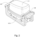
- FIG. 2 to 5 there is shown is a schematic illustration of one embodiment of a modular multi-fuel cooking appliance. While the illustration is a modular three-mode hybrid grill, it should be appreciated that embodiments of the invention may embrace only two modes or more than three modes, such as for example a gas and electric, or gas and coal, or electric and coal dual-fuel barbeque cooking appliance.
- an outer cooking chamber 201b is provided to accommodate one of a plurality of interchangeable cooking modules A, B, C, D and E.
- the outer cooking chamber has a plurality of feet 207 for supporting it on the ground or a supporting surface.
- the interchangeable cooking modules A, B, C, D, E comprise an inner cooking module member 201 each of which has different heat generating fuel means.
- the outer cooking chamber 201b includes a base and a plurality of enclosing sidewalls extending up from the base. At least one, and preferably two, of the sidewalls is provided with a rib or protrusion 202b on which can be supported one of the interchangeable cooking modules A, B, C, D, E.
- the base of outer cooking chamber 201b includes an opening 206a into, or below, which a drip tray 206 is accommodated for catching oils, fats, or fluids released from food during cooking.
- Each of the interchangeable cooking modules A, B, C, D, E comprises an inner cooking module member 201 and a grill plate cooking surface 204.
- the grill plate cooking surface 204 may form a part of the interchangeable cooking module or may be removably supported above the inner cooking module member 201 such that the grill plate cooking surface is itself interchangeable between different ones of the cooking modules.
- the cooking modules A, B, C, D, E are preferably interchangeably supported with the outer cooking chamber 201b by the rib or protrusion 202b such that the cooking appliance may be configured to operate with different kinds of cooking fuel, such as for example gas, electric, or hot charcoal (coals) as desired by the user.
- the inner cooking member 201 is adapted to accommodate coals 146 such that the cooking appliance can be configured for cooking over hot coals as shown in Figure 3 .
- the inner cooking member 201 is provided with an electric cooking element 203 and a gas cooking element 202 in a single-sided linear configuration as will be described with reference to Figure 27 .
- the cooking appliance can be configured as a dual-fuel electric/gas cooking appliance.
- the outer cooking chamber 201b is provided with slots or openings in its sidewalls to accommodate an electric power cord 203a or gas line 202a as required.
- the advantage of the second interchangeable cooking module B being of a dual-fuel electric/gas type is that only two interchangeable cooking modules A, B are required for the multi-fuel cooking appliance to be configured with three cooking fuels of electric, gas, hot coals.
- a dual-fuel rotatable cooking unit as described with reference to Figures 9 to 14 and/or as described in United States patent publication no. US2018073739 published on 15 March 2018 may be used within the outer cooking chamber 201b.
- an invertible dual fuel cooking module E may be used may be used within the outer cooking chamber 201b.
- an invertible dual fuel cooking module E includes an inner cooking module member 201 supporting a first electric cooking fuel mode 203 and a second cooking fuel mode 202 spaced apart by 180-degrees.
- the inner cooking module member 201 also supports a reflector 208 interposed between and delimiting the cooking fuel modes 202, 203.
- the invertible dual fuel cooking module E is swapped between a gas cooking mode and an electric cooking mode (or vice versa) by removing the cooking module E from the outer cooking chamber 201b, flipping or inverting the cooking module E 180 degrees as illustrated by arrow 209, and then replacing the cooking module E with the opposite fuel mode in the upper operable orientation.
- the multi-fuel cooking appliance may be configured solely as a gas cooking appliance, or solely as an electric cooking appliance. Accordingly, in some embodiments there may be provided an interchangeable cooking module C that is provided solely with an electric cooking element 203, or another embodiment of the interchangeable cooking module D to be provided only with a gas element 202.
- the inner cooking member 201 may be a simple supporting frame or may include an inner base and inner side walls to form an inner cooking chamber. Such an inner cooking chamber embodiment may optionally include an opening 206b arranged to communicate with opening 206a and drip tray 206 when the cooking chamber 201 is accommodated for use with the outer cooking chamber 201b.
- the inner cooking member 201 is a simple supporting frame supporting the electric or gas or combination electric/gas cooking elements 202, 203 and may be removably accommodated directly within the outer cooking chamber 201b without its own separate inner cooking chamber.
- the cooking elements 202, 203 may be removed and replaced with an inner cooking chamber for accommodating hot coals 146.
- the hot coals 146 may be placed directly in the outer cooking chamber without the need for an inner cooking chamber to accommodate the hot coals. It is recognized however that cooking with hot coals directly in the outer cooking chamber 201b will increase the rate of deterioration of the outer cooking chamber 201b and thus the lifespan of the multi-fuel cooking appliance.
- gas burners and electric elements are for illustration purpose only, and a number of varieties of burners or elements may be substituted in any configuration without departing from the scope of the invention.
- the cooking modules A, B, C, D, E may be not interchangeable. In some embodiments, the cooking modules A, B, C, D, E are arranged in such a way that one cooking module of the cooking modules A, B, C, D, E is coupled to the lid 211 whereas another one of the cooking modules A, B, C, D, E is coupled to the base.
- the two modules are preferably of different types.
- a barbecue grill assembly 101 with a support frame assembly including a base 106, front frame member 102 extending vertically from the base 106, a rear frame member 103 extending vertically from the base 106, and a pair of side frame members 104, 105 that connects the front and rear frame members 102, 103.
- the base 106 may be supported on feet or wheels or a combination of feet and wheels.
- the barbecue grill assembly 101 further comprises a cooking chamber 110 supported on the support frame assembly.
- the cooking chamber 110 including at least a first pair of opposing side walls 120, 121 and a second pair of opposing side walls 122, 123.
- the pairs of side walls define an opening 113 into an interior space 112 of the cooking chamber 110.
- a cover or lid 111 is hingeably connected to a rear one 123 of the second pair of side walls of the cooking chamber.
- the lower edges of at least one of the first or second pairs of opposed side walls 120, 121, 122, 123 comprises mounting features that engages a limited extent with corresponding frame members 102, 103, 104,105 when the cooking chamber 110 is connected to the support frame assembly.
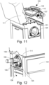
- a receiver hub assembly 125 with an opening 126 for interchangeably receiving a receivable hub 132 of a dual-fuel rotatable cooking unit 130 described with reference to Figures 9 to 14 , or a single fuel cooking unit such as electric cooking element 203 and a gas cooking element 202 described with reference to Figures 3 to 5 .
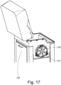
- the receiver hub assembly opening 126 may also accommodate a variable vent or flue unit 127.
- An optional door 128 may be provided in the rear frame member 103, as illustrated in Figures 6 and 7 , to provide additional ventilation of the grill unit.
- the optional door 128, if provided, can be opened to provide ventilation for gas or charcoal (hereinafter just coal) cooking as necessary, but closed for, say, an electric cooking mode.
- the front, rear, left and right side members 102-105 may be double walled frame members for heat insulation.
- the double walled frame members 102-105 include heat resistant insulation between the double wall skins.
- the cooking chamber walls 120-123 and cover 111 may also comprise double walled members with or without insulation for heat insulation.
- the dual-fuel rotatable cooking unit 130 may be of a type described in US2018073739
- the dual-fuel rotatable cooking unit 130 has at least a first cooking mode 133 and a second cooking mode 134, spaced apart by 180-degrees, and a reflector 135 interposed between and delimiting the cooking modes 133, 134.
- the reflector 135 is movably located between the two cooking modes 133, 134 and has a drip hole formed centrally.
- the reflector 135 has a first and second reflective surfaces and it may have a straight profile, or a curved profile which is beneficial for enhancing heat radiation.
- the first cooking mode consists of a first cooking mode element, which is a gas heating element 133 that is connected with the gas regulator 136 of the receivable hub 132.
- the second cooking mode consists of a second cooking mode element, which is an electric heating element 134 that is connected with the electrical power inlet 137 of the receivable hub 138.
- An electric element regulator 168 with a power cord 139 is connectable with the electrical power inlet 137 for providing a regulated electric power supply to the electric heating element 134.
- the rotatable cooking unit 130 is rotatable by rotating the receivable hub 132 within the receiver hub 125 of the cooking chamber through preferably 180 degrees to alternatively select a preferred one of the dual-fuel cooking modes.
- the second cooking mode is adjacent the concave side of the reflector as the profile of the reflector will enhancing heat radiation of the electric heating element 134 of the second cooking mode element, which has a different heat generating characteristic to the first cooking mode element.
- a third cooking mode of the barbecue is a charcoal (coal) mode of cooking fuel.
- a charcoal bin 140 or container which may be made from cast iron or other metal materials such as stainless steel and the like.
- the charcoal bin 140 includes a base and at least a first pair of opposing side walls 141, 143 and a second pair of opposing side walls 142, 144 extending upwardly from the base in order to define a chamber 145 between the walls for retaining heated coals 146.
- An outwardly extending flange or lip 147 is provided at a top rim of the four side walls 141-144 of the container to provide a supporting means for the bin 140 within the cooking chamber 110 of the barbecue.
- the rotatable cooking unit 130 is removed in the manner shown in Figure 11 and can be replaced with the variable vent or flue means 127 illustrated in Figure 17 .
- the charcoal bin 140 of Figure 15 is disposed within the cooking chamber 110/ interior space 112 of the barbecue and provides a third-fuel cooking mode of the barbecue being a coal cooking mode.
- the modular multi-fuel cooking appliance is generally available in gas or electric powered configuration.
- the appliance of Figure 2 may have interchangeable cooking modules described with reference to Figures 3 to 5 and/or 6 to 17.
- a dual-fuel rotatable cooking unit 130 was described with reference to Figures 9 to 14 and/or US2018073739 .
- a single-sided linear gas electric dual fuel module may incorporate the gas and electric elements together in a single side as illustrated and described with reference to Figure 27 .
- a gas electric dual-fuel cooking module may include an invertible cooking module as described with reference to Figure 3A , such that the dual-fuel module may be removed, flipped or inverted 180 degrees and then replaced with the opposite fuel mode operable.
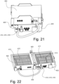
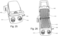
- FIG. 18 to 20 , 21, 22, 23 , 24 , 25, 26 there shown is embodiments of multi-fuel cooking appliance according to aspects of the invention.
- an outer case having an upper case half 402 and a lower case half 403.
- the lower case half 403 has feet 404 for supporting the grill 400 on a work surface.
- the upper case half 402 and lower case half 403 are hingedly joined along one edge by a hinge joint 405 to be moveable between a closed configuration and an open configuration.
- the lower case half may be a lid
- the upper case half may be a base.
- the upper case half may be a lid, and the lower case half may be a base.
- the upper case half 402 and lower case half 403 are positioned to oppositely face each other with a food cooking space 406 between the upper case half 402 and lower case half 403.
- the hinge 405 is an articulating hinge joint, or a floating hinge, or a lost motion type with for instance the pintles running in slots to allow varying distance from top to bottom plate to provide a variable food cooking space 406 between the closed upper case half 402 and lower case half 403 to accommodate various thicknesses of food.
- each of the upper case half 402 and lower case half 403 are each arranged to accommodate a cooking module, such as one of the cooking modules as herein described with reference to Figures 3 to 5 and/or 6 to 17.
- a cooking module such as one of the cooking modules as herein described with reference to Figures 3 to 5 and/or 6 to 17.
- Each of the cooking modules in the upper case half 402 and lower case half 403 can be interchangeable, or they can be non-interchangeable (e.g., fixed).
- upper and lower gas elements 410, 411 are controlled by respective gas regulators 414, 415 located optionally on a front edge of the upper case half 402 and lower case half 403.
- the upper and lower gas elements 410, 411 are controlled by a single gas regulator located on one of the upper case halves 402 and lower case half 403, or in some embodiments a single gas regulator located co-axial with the hinge 405, as shown in Figure 20 .
- the upper case half 402 and lower case half 403 may open 180 angular degrees so both may lay flat doubling the area for single side grilling.
- a single gas regulator may be located co-axial with the hinge 405 and supplied from a single gas bottle or supply (not shown).
- the upper case half 402 and lower case half 403 are coupled via a hinge 405.
- the upper case half 402 is a body, optionally with handle, which can be used as a lid
- the lower case half 403 is a base.
- the body is generally dome shape and is made of steel.
- a grill plate is arranged on and removably attached to the body. Inside the body there is gas element 410 controlled by one or more gas regulators 414, 415, 416 providing a gas burner.
- a die cast electric grill plate 444 is arranged on, and removably attached to, the base.
- the die cast electric grill plate has a staked-in heating element that preferably operates using electricity.
- the upper and lower case halves 402, 403 are movable between open and closed (or substantially closed, when a food item is placed therebetween) configurations.
- the grill plate and the die cast electric grill plate are arranged on substantially the same plane or on substantially parallel planes.
- the grill plate and the die cast electric grill plate are arranged in generally facing relation to each other.
- clasp(s) may be provided to lock the upper and lower case halves 402, 403 when in the closed configuration.
- the appliance in Figure 23 provide two separate cooking surfaces, which can be used selectively or simultaneously (by operating the gas element and/or the electric grill plate as needed), when in the open configuration.
- the upper case half 402 can be the base and the lower case half 403 can be the lid.
- the appliance in Figure 23 provides an electric grill in one half, and a gas only bbq/grill in another half.
- the appliance can be used for indoor grill or outdoor grill.
- the upper case half 402 and lower case half 403 are coupled via a hinge 405.
- the upper case half 402 is a body, optionally with handle, which can be used as a lid
- the lower case half 403 is a base.
- a grill plate is arranged on and removably attached to the body.
- a dual-fuel rotatable cooking unit 131 such as the one described with reference to Figures 9 to 14 and/or illustrated in US2018073739 .
- Another grill plate is arranged on, and removably attached to, the base.
- a gas element 410 controlled by one or more gas regulators 414, 415, 416 providing a gas burner.
- the upper and lower case halves 402, 403 are movable between open and closed configurations. In the open configuration the grill plates are arranged on substantially the same plane or on substantially parallel planes. In the closed configuration, the grill plates are arranged in generally facing relation to each other. Optionally clasp(s) may be provided to lock the upper and lower case halves 402, 403 when in the closed configuration.
- the appliance in Figure 24 provides two separate cooking surfaces, which can be used selectively or simultaneously when in the open configuration.
- the upper case half 402 can be the base and the lower case half 403 can be the lid.
- the appliance in Figure 24 provides a rotary dual-mode bbq/grill (electric & gas) in one half, and a gas only bbq/grill in another half. The appliance can be used for indoor grill or outdoor grill.
- the clamshell grill may include interchangeable fuel modules in the configurations such as modules A, B, C, D and E hereinbefore described with reference to Figures 3 and 3A to 5 and 27, and/or a dual-fuel rotatable cooking unit 130 described with reference to Figures 9 to 14 and US2018073739 .
- the element may be as shown, or in hard contact with or more normally, cast/embedded into the hotplate material.
- the unit may not utilize any hot plates at all and cook by radiation only from electric elements 203 or gas element 202 radiation, preferably from surface gas burners or the like, especially on the top half radiating downwards.
- the invention is not limited to metal sheathed electric elements, as open wire type as seen in toasters, and tubular quartz enclosed wire wound elements area are also envisaged. Infra-red bulbs may also be utilized.
- Figure 27 is a view of the plan (top or birds-eye) view of a single-sided linear configuration multi-fuel cooking module 301 of another embodiment of a multi-fuel barbecue grill according to some aspects of the invention. Shown is the lower body of cooking chamber 301. A gas burner element 302 in straight configuration, and the serpentine shaped electric element 303 and disposed together in the chamber 301, such that there is no need to rotate or change the cooking element module as in aforementioned embodiments. Both cooking fuel elements 302, 303 co-exist in the cooking chamber 301.
- the serpentine electric element 303 is arranged with two elongate loops or fingers extending away from the hub end on either side of the gas element 302.
- the two fingers are connected to form a series element by a web section between the proximate non-terminal hub ends of the fingers.
- the web section of the element 303 does not cross the gas burner in any flame areas of the gas element 302. It has been found however that if the element 303 does cross the burner flame areas that the materials used in the construction of the element can withstand the expected temperatures caused by the gas flames, so an element of almost any shape may be employed.
- the gas and electric elements 302, 303 may both be shaped in for instance serpentine shapes, or differently, such that in combination the electric element 303 does not cross direct flame areas of the gas element 302.
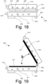
- Figure 28 shows an end section view of the barbecue of Figure 27 .
- a grill plate cooking surface 304 is shown disposed above or planar with the gas element 302 and electric element 303 which are mounted in the same cooking chamber 301.
- the electric element 303 is shown mounted above the gas burner 302 so as to be closer to the grill plate 304 and/or food for good cooking performance. However, the element may be mounted above, below, or side-by-side with the gas burner 302.
- a reflector 305 is shown to enhance the upward radiation of the electric element 303, a similar part may be mounted below the gas burner 302 as a heat shield for the bottom surface of the cooking chamber 301.
- a drip tray 306 is provided inside or externally to the cooking chamber 301.
- Figure 29 shows a vertical configuration of the barbecue grill.
- An end cross section view of a vertical grill is shown.
- an outer case 311 may be of a frustoconical configuration, or in first or second pairs of opposed side walls defining a vertical cooking chamber an upper (top) opening.
- a removable clamshell food holding rack 310 is removably receivable through the upper opening into the cooking chamber and held approximately on the centerline of the unit.
- Each side of the food rack 310 accommodates an electric cooking element 313. Outside the electric element 313 is preferably a surface combustion gas burner hot surface 307 and burner case 308.
- Food items 212 are placed in the clamshell rack 310 and the rack 310 and food 212 inserted into the allotted space in the cooking chamber formed between the gas burners 307 and electric elements 313.
- the electric heating elements 313 may be omitted such that the arrangement is a gas only version of this configuration.
- Burners 307 of different configurations may be utilized in any version without departing from the scope of the invention as defined by the claims. Again, for efficiency it is shown, and preferred, that the electric elements 313 are closer to the food cooking area than the gas burners 307.
- the elements 313 are designed to handle the gas temperatures when in gas mode with power off.
- Figure 30 depicts a further embodiment where the gas burner 302 and electric element 303 track the shape of each other and are mounted in contact or close to each other. The intention here is that each element keeps the other quite hot to reject fat and other fluids if they drip onto the elements.
- a barbeque cooking appliance is disclosed that is of any of the configurations described above, which is larger in effective cooking area than is usual. (For example, 50% to 100% larger for built in or trolley type barbeque cooking appliances)
- the cooking performance of very large barbeque cooking appliances to sear and cook meats etc. would be unacceptable mainly because the temperature of the element is lower than needed to sear food and for plug-in appliances the allowable max power is limited.
- the power available from a single outlet is normally 1800 watts maximum.
- Europe and Australia 2200-2400 watts are available.
- Even extended cooking times on a cooler plate cannot attain searing, only "stewing", a term used in the industry.
- a barbeque cooking appliance in which the total apparent wattage is in excess (e.g., approx. two times) of the maximum allowable.
- the invention uses these elements in such a way that the apparent wattage of all elements is controlled, so that the maximum actual recorded wattage at any one time is not in excess of that allowable by regulation for the supply connection.
- the period may be as short as 1 second out to several minutes and the invention does not limit any combination of power splits.
- the control of the power "split" between elements 1 and 2 may be instigated by temperature of grill or food, time, other sensors, fuzzy logic or any other technique that attains the desired result and does not violate the maximum watts allowance for plug-in units at the relevant voltage.
- FIG. 31 A table is shown that illustrates control aspects of some embodiments of the invention.
- the left-hand axis 331 shows % Power.
- the different controlled modes 334 indicate the relative power to each element at a given time. This is for illustration only and one embodiment would enable infinite control of the split of power between the elements.
- the invention is not limited by how many elements are to be controlled in this manner but at least two will be involved.
- the actual power axis 333 expresses the % power as Watts of power, and the approximate temperature chart 335 illustrates how temperatures may vary with wattage. (Illustrative only).
- element 1 and element 2 are both held at a 50% energy level, the unit power consumption is therefore two times 50% but the element temperature is only 300-deg Celsius, not glowing.
- the differential split of power can be varied to at least drive at least one element to a grilling or desired temperature well above what could be attained by a normal control which would have the elements at a nominal 1600 watt maximum.
- Shown at D and E are the reverse applications of power where 1 is cooler and 2 is hotter.
- a differential splitting of the elements preferably with an infinite control or a multi-step controller (preferably a Pulse Width Modulation control), will allow the operator to attain whatever temperatures they wish on any given element within the range available, as partially illustrated in Figure 31 . It is also disclosed that the control may be manually adjusted or be under automatic control to attain good cooking on both sides of the barbeque cooking appliance even though the power is still within the regulatory defined limits.
- a multi-step controller preferably a Pulse Width Modulation control
- the unit can be controlled in infinite number of steps to the limit of 1800 Watts on one element only and zero watts on the other, and thus will be able to deliver searing/browning power as, if two 1800 Watts were available. Of course, it would be at a slightly slower rate, because up to 1800 watts would be available on one element only at one time if required. It has been found however that the unit, once preheated, has a thermal flywheel effect that helps keep temperatures quite hot and depending on the cycle profile the reheat time for any suppressed element is quite short. This peak wattage performance on each plate is not possible on existing barbeque cooking appliances.
- the control shown at Figure 32 would include a single user control 322 that supplies a differential amount of energy to each plate.
- the chart indicates two 1800-watt elements with a left side element (wattage chart) 320 and a right-hand element (wattage chart) 321.
- the line 323 indicates that the left-hand wattage is very low and the right-hand wattage is almost at maximum.
- the knob 322 is rotated further clockwise the line 323 moves to the position described at line 324 which has increased the left side and reduced the right side in the same proportion.
- knob clockwise indicates at 325 a 50-50 split from left side to right side 309, i.e., 900 watts each, and at the limit shown at 326 the right side has maximum wattage and the left-hand side has almost zero. It can be seen that at no point does the sum of the wattages exceed the nominal statutory maximum of 1800 watts.
- the wattages expressed here are for illustration purposes only.
- FIG. 33 one embodiment includes manual control shown as a control knob 327 which is the physical version of the central control 322 in Figures 31 and 32 above. It shows a left side 328 and a right side 329. The effect of turning the knob 327 has the same effect as shown in Figure 32 .
- the use of a single control knob not only simplifies the use, but most importantly keeps both sides in inverse synchronization ensuring that the unit cannot exceed the allowable maximum at any point in time.
- a grill plate 425 of generally larger surface area than can be heated by a single electrical connection is shown in Figure 34 .
- a first heating system of combined electrical / gas heating cooking unit 426 is shown.
- a second heating unit powered by gas-only 427 is shown.
- a barbeque cooking appliance of the type described in Figure 34 has approx. 50% of the area heated by either gas or electric, and the other half heated by gas only. In this way a larger barbeque cooking appliance is provided.
- Mode 1 50% area on power or gas, utilizing cooking unit 426 and 100% area on gas if no electric power is available, utilizing the gas portion of cooking unit 426, and the gas only portion 427. It can be therefore seen that one appliance can offer the convenience of cooking on 50% area electrically, and 50%-100% area cooking when on gas. Any appropriate split of power side to side is allowed for in the design. It is also foreseen that the invention applies to two or more heating units in a single barbeque cooking appliance unit.
- the electric tubular elements in any of the configurations depicted above may be integrated with the plate by force fit, or direct insert casting into the hot plate cooking surface as in a sandwich maker/clamshell type of barbeque cooking appliances/grills. It is also applicable in electric grills as depicted in Figures 18 to 20 , 21, 22, 23 , 24 , 25 , and 26 as it delivers heat to the food by direct conduction and the limited electric power is thus used efficiently.
- FIG 35 illustrates, schematically, an embodiment of a (modular) cooking appliance 1000 in one embodiment not forming part of the invention.
- the cooking appliance 1000 includes a first cooking module 1000A and a second cooking module 1000B, e.g., operably connected with the first cooking module 1000A.
- the first cooking module 1000A includes a first cooking chamber 1002A, a first cooking element 1004A arranged in the first cooking chamber 1002A, and a first cooking surface 1006A.
- the first cooking element 1004A is arranged to be heat the first cooking surface 1006A.
- the second cooking module 1000B includes a second cooking chamber 1002B, a second cooking element 1004B arranged in the second cooking chamber 1002B, and a second cooking surface 1006B.
- the second cooking element 1004B is arranged to be heat the second cooking surface 1006B.
- the first cooking element 1004A includes one of, or at least one of: an electric cooking element, a gas cooking element, a combination of electric and gas cooking elements, or a bin having a chamber for accommodating hot coals.
- the second cooking element 1004B comprises one of, or at least one of: an electric cooking element, a gas cooking element, a combination of electric and gas cooking elements, or a bin having a chamber for accommodating hot coals.
- the first and second cooking elements 1004A, 1004B are different types of cooking elements.
- the first cooking element 1004A is gas cooking element and the second cooking element 1004B is electric cooking element.
- the first cooking element 1004A is a combination of electric and gas cooking elements and the second cooking element 1004B is a gas cooking element.
- the first cooking element 1004A is a combination of electric and gas cooking elements and the second cooking element 1004B is an electric cooking element.
- first and second cooking elements 1004A, 1004B are the same type of cooking elements.
- both the first and second cooking elements 1004A, 1004B are gas cooking elements.
- both the first and second cooking elements 1004A, 1004B are the dual-fuel rotatable cooking unit 130 described with reference to Figures 9 to 14 and/or as described in United States patent publication no. US2018073739 .
- the two cooking elements 1004A, 1004B share the same gas/power source.
- the two cooking elements 1004A, 1004B use different gas/power sources.
- the first cooking element 1004A is removable from the first cooking module.
- the first cooking element 1004A is non-removable from the first cooking module.
- the second cooking element 1004B is removable from the second cooking module.
- the second cooking element 1004B is non-removable from the second cooking module.
- the combination of electric and gas cooking elements includes independently controllable electric cooking element and gas cooking element.
- the combination of electric and gas cooking elements includes simultaneously or alternately operated electric cooking element and gas cooking element.
- the combination of electric and gas cooking elements are arranged in a rotatable assembly, such as the one described with reference to Figures 9 to 14 , such that they can rotated about a rotation axis to selectively use electric or gas.
- the first cooking surface 1006A is removable from the first cooking module.
- the first cooking surface 1006A is non-removable from the first cooking module.
- the second cooking surface 1006B is removable from the second cooking module.
- the second cooking surface 1006B is non-removable from the second cooking module.
- the first and second cooking surfaces 1006A, 1006B are of the same shape and/or size.
- the first cooking surface 1006A is provided by, at least, a cooking plate, a grill plate, a grill, a grill mesh, a griddle plate, an electric die cast grill plate, etc.
- the second cooking surface 1006B is provided by, at least, a cooking plate, a grill plate, a grill, a grill mesh, a griddle plate, an electric die cast grill plate, etc.
- the first and second cooking surfaces 1006A, 1006B are the same or different types of surfaces.
- the first cooking element 1004A is integrated with the first cooking surface 1006A as a single piece or member or assembly.
- the first cooking element 1004A is embedded in a means or device or element (e.g., a cooking plate, a grill plate, a grill, a grill mesh, a griddle plate, an electric die cast grill plate, etc.) that provides the first cooking surface 1006A.
- a means or device or element e.g., a cooking plate, a grill plate, a grill, a grill mesh, a griddle plate, an electric die cast grill plate, etc.
- the second cooking element 1004B is integrated with the second cooking surface 1006B as a single piece or member or assembly.
- the second cooking element 1004B is embedded in a means or device or element (e.g., a cooking plate, a grill plate, a grill, a grill mesh, a griddle plate, an electric die cast grill plate, etc.) that provides the second cooking surface 1006B.
- a means or device or element e.g., a cooking plate, a grill plate, a grill, a grill mesh, a griddle plate, an electric die cast grill plate, etc.
- first and second cooking surfaces 1006A, 1006B are separate but form a continuous surface (e.g., arranged side by side when in the open configuration).
- the first cooking module includes one or more of: a stand, one or more legs, one or more handles, or movement means (wheels, casters, etc.).
- the second cooking module includes one or more of: a stand, one or more legs, one or more handles, or movement means (wheels, casters, etc.).
- the first and second cooking modules are arranged on, e.g., attached to, mechanically and/or magnetically, the same surface, which is preferably a flat surface, or on different surfaces in substantially the same plane.
- the surface(s) is/are provided by a cart, a bench, a table, cart, which optionally has leg(s), wheel(s), etc.
- the cooking appliance further comprises a lid for the first cooking module.
- the lid may also be used as a lid for the second cooking module.
- the cooking appliance further comprises a lid for the second cooking module.
- the lid may also be used as a lid for the first cooking module.
- the cooking appliance further comprises two lids, one for each of the first and second cooking modules.
- the two lids may be of the same shape, size, height, form, etc.
- the lid may include no cooking element.
- the lid may be hinged to the cooking module, or may be a loose lid removably coupleable to the cooking module.
- the first and second cooking modules form first and second cooking halves of the cooking appliance.
- the two halves can be of the same shape, size, form, etc.
- the cooking appliance further includes a connector connecting the first and second cooking modules.
- the connector is integrated with one or both of the first and second cooking modules, or it is removably coupled with one or both of the first and second cooking modules.
- the connector comprises a hinge arranged between the first and second cooking modules.
- the cooking appliance is movable between a substantially closed configuration, in which the first and second cooking surfaces 1006A, 1006B generally face each other, and an open configuration, in which the first and second cooking surfaces 1006A, 1006B are not in facing relation with each other (e.g., the first and second cooking surfaces 1006A, 1006B are arranged in substantially the same plane).
- the cooking appliance 1000 further includes a locking means arranged on the first and/or second cooking modules to lock the first and/or second cooking modules in the closed configuration.
- the locking means may include a clasp, a latch, etc.
- the locking means may be arranged on the first and/or second cooking modules on an opposite side of the hinge.
- the cooking appliance 1000 further includes a rotisserie spit rod / spit rod forks arranged in the first and/or second cooking chambers 1002A, 1002B, e.g., between the first and second cooking surfaces 1006A, 1006B.
- the cooking appliance 1000 further includes a motor arranged to rotate the rotisserie spit rod / spit rod forks.
- the motor may be powered by DC (e.g., battery) or AC.
- the cooking appliance 1000 may be "powered" by gas (fuel) or electricity (AC and/or DC, e.g., battery) as appropriate.
- the battery may be rechargeable.
- the cooking appliance 1000 is portable.
- the cooking appliance 1000 is an indoor cooking appliance.
- the cooking appliance 1000 is an outdoor cooking appliance.
- the cooking appliance 1000 is an indoor-and-outdoor cooking appliance.
- the cooking appliance 1000 is a benchtop cooking appliance.
- the cooking appliance 1000 is a clamshell type cooking appliance, a contact grill type cooking appliance, etc.
- the cooking appliance 1000 embodiment of Figure 35 can be implemented in or incorporated into, among other things, any of the device embodiments disclosed and illustrated in the drawings.
- the cooking appliance 1000 may include additional cooking modules (similar or the same as cooking modules 1000A, 1000B).
- Figure 36 shows one embodiment of a cooking appliance 1100 based on the design in Figure 35 .
- the two cooking modules 1100A, 1100B are both mounted, fixedly or movably or removably, on a platform or surface 1110 provided by a wheeled cart 1112.
- the two cooking modules1100A, 1100B do not touch each other in this example.
- the surface 1110 may include recesses each configured to receive a cooking module.
- Figure 37 shows one embodiment of a cooking appliance 1200 based on the design in Figure 35 .
- This design is similar to that in Figure 36 , except that the two cooking modules are shown to include leg(s) and/or wheel(s) 1216, and that the wheeled cart 1212 includes a cabinet 1214, which allows storage of, e.g., foodstuff, the lids for the cooking modules 1200A, 1200B, kitchen utensils, etc.
- Figure 38 shows one embodiment of a cooking appliance 1300 based on the design in Figure 35 .
- the two cooking modules 1300A, 1300B are hingedly connected together via a hinge 1320.
- FIG 39 shows one embodiment of a cooking appliance 1400 based on the design in Figure 35 .
- This design is similar to that in Figure 38 , except that one of the cooking modules 1400B includes a handle 1422B and a locking member 1424B for locking the appliance 1400 when closed.
- Figure 40 shows one embodiment of the cooking appliance 1500 of Figure 35 . This design is similar to that in Figure 38 , except that the cooking surfaces 1506A, 1506B are arranged further deep inside the respective cooking chamber 1502A, 1502B.
- Figure 41 shows one embodiment of the cooking appliance 1500 of Figure 40 in the closed configuration.
- the cooking appliance 1500 can include a rotisserie (hot shown) incorporated or arranged therein, between the two cooking surfaces 1506A, 1506B.
Landscapes
- Engineering & Computer Science (AREA)
- Food Science & Technology (AREA)
- Chemical & Material Sciences (AREA)
- Combustion & Propulsion (AREA)
- Mechanical Engineering (AREA)
- General Engineering & Computer Science (AREA)
- Baking, Grill, Roasting (AREA)
Claims (14)
- Kochgerät (1300; 1400; 1500), umfassend:ein erstes Kochmodul (402; 1300A; 1400A; 1500A) und ein zweites Kochmodul (403; 1300B; 1400B; 1500B), die so angeordnet sind, dass sie gelenkig an einer Kante angrenzend verbunden sind, so dass sie schwenkbar zwischen einer offenen Konfiguration und einer im Wesentlichen geschlossenen Konfiguration bewegt werden können;wobei das erste Kochmodul eine erste Kochkammer (1302A; 1402A; 1502A), ein erstes Kochelement (1304A; 1404A; 1504A), das in der ersten Kochkammer angeordnet ist, und eine erste Kochfläche (1306A; 1406A; 1506A) umfasst, wobei das erste Kochelement angeordnet ist, um die erste Kochfläche zu erhitzen;das zweite Kochmodul eine zweite Kochkammer (1302B; 1402B; 1502B), ein zweites Kochelement (1304B; 1404B; 1504B), das in der zweiten Kochkammer angeordnet ist, und eine zweite Kochfläche (1306B; 1406B; 1506B) umfasst, wobei das zweite Kochelement angeordnet ist, um die zweite Kochfläche zu erhitzen;dadurch gekennzeichnet, dass das erste Kochelement Folgendes einschließt: eine Kombination aus elektrischen und Gas-Kochelementen, die in einer drehbaren Anordnung angeordnet sind, die um eine Rotationsachse drehbar ist, um wahlweise Strom oder Gas zu verwenden, undwobei das zweite Kochelement Folgendes einschließt: ein elektrisches Kochelement, ein Gaskochelement, eine Kombination aus elektrischen und Gaskoch-Elementen oder einen Behälter der eine Kammer zum Aufnehmen von heißen Kohlen aufweist.
- Kochgerät (1300; 1400; 1500) nach Anspruch 1, wobei das erste und das zweite Kochelement unterschiedliche Arten von Kochelementen sind.
- Kochgerät nach Anspruch 1, wobei das zweite Kochelement aus einem GasKochelement besteht.
- Kochgerät nach Anspruch 1, wobei das erste und das zweite Kochelement jeweils aus einer Kombination von elektrischen und Gas-Kochelementen bestehen, die in einer drehbaren Anordnung angeordnet sind, wobei die drehbare Anordnung um eine Rotationsachse drehbar ist, um wahlweise Strom oder Gas zu verwenden.
- Kochgerät (1300; 1400; 1500) nach einem der vorhergehenden Ansprüche, wobei in der offenen Konfiguration die erste und zweite Kochfläche im Wesentlichen in der gleichen Ebene liegen, und wobei in der im Wesentlichen geschlossenen Konfiguration die erste und die zweite Kochfläche im Allgemeinen einander gegenüberliegen.
- Kochgerät (1300; 1400; 1500) nach einem der Ansprüche 1 bis 5, wobei das erste Kochelement herausnehmbar in der ersten Kochkammer gestützt ist.
- Kochgerät (1300; 1400; 1500) nach einem der Ansprüche 1 bis 6, wobei das zweite Kochelement herausnehmbar in der zweiten Kochkammer gestützt ist.
- Kochgerät (1300; 1400; 1500) nach einem der Ansprüche 1 bis 5,
wobei das erste Kochelement herausnehmbar in der ersten Kochkammer gestützt ist; wobei das zweite Kochelement herausnehmbar in der zweiten Kochkammer gestützt ist; und wobei das zweite Kochelement so angeordnet ist, dass es in der ersten Kochkammer herausnehmbar gestützt ist, wenn das erste Kochelement aus der ersten Kochkammer entfernt wird und das zweite Kochelement aus der zweiten Kochkammer entfernt wird. - Kochgerät (1300; 1400; 1500) nach Anspruch 6 oder 8, ferner umfassend ein drittes Kochelement, das Folgendes einschließt: ein elektrisches Kochelement, ein Gaskochelement oder einen Behälter der eine Kammer zum Aufnehmen von heißen Kohlen aufweist; wobei das dritte Kochelement so angeordnet ist, dass es herausnehmbar in der ersten Kochkammer gestützt ist, wenn das erste Kochelement aus der ersten Kochkammer entfernt wird.
- Kochgerät (1300; 1400; 1500) nach einem der Ansprüche 1 bis 9,
wobei die erste und zweite Kochfläche so angeordnet sind, dass sie unabhängig voneinander ausschließlich durch die jeweiligen ersten und zweiten Kochelemente beheizt werden. - Kochgerät (1300; 1400; 1500) nach einem der Ansprüche 1 bis 10,
wobei die erste und die zweite Kochfläche so angeordnet sind, dass sie obere und untere Flächen eines Lebensmittels gleichzeitig durch Kontakt erhitzen. - Kochgerät (1300; 1400; 1500) nach einem der Ansprüche 1 bis 11,
wobei das Kochgerät ein Zweischalen- oder Kontaktgrill-Kochgerät ist. - Kochgerät (1300; 1400; 1500) nach einem der Ansprüche 1 bis 12,
wobei das erste Kochmodul als Deckel für das zweite Kochmodul fungiert. - Kochgerät (1300; 1400; 1500) nach einem der Ansprüche 1 bis 13, wobei das Kochgerät ein Indoor-Outdoor-Hybrid-Kochgerät ist.
Applications Claiming Priority (4)
| Application Number | Priority Date | Filing Date | Title |
|---|---|---|---|
| AU2020901078A AU2020901078A0 (en) | 2020-04-06 | DUAL FUEL GAS ELECTRIC or ALL GAS COOKING APPLIANCE | |
| US202063022575P | 2020-05-10 | 2020-05-10 | |
| AU2020901576A AU2020901576A0 (en) | 2020-05-15 | DUAL FUEL GAS/ELECTRIC or ALL GAS COOKING APPLIANCE | |
| US202117161897A | 2021-01-29 | 2021-01-29 |
Publications (3)
| Publication Number | Publication Date |
|---|---|
| EP3892171A1 EP3892171A1 (de) | 2021-10-13 |
| EP3892171C0 EP3892171C0 (de) | 2025-04-23 |
| EP3892171B1 true EP3892171B1 (de) | 2025-04-23 |
Family
ID=75426388
Family Applications (1)
| Application Number | Title | Priority Date | Filing Date |
|---|---|---|---|
| EP21167042.7A Active EP3892171B1 (de) | 2020-04-06 | 2021-04-06 | Kochgerät |
Country Status (3)
| Country | Link |
|---|---|
| EP (1) | EP3892171B1 (de) |
| CN (1) | CN113491450A (de) |
| AU (1) | AU2021202082A1 (de) |
Families Citing this family (5)
| Publication number | Priority date | Publication date | Assignee | Title |
|---|---|---|---|---|
| US11796180B2 (en) * | 2019-09-16 | 2023-10-24 | Enerco Group Inc. | Systems and arrangements for portable heater with connectable accessory |
| FR3140254B1 (fr) * | 2022-09-30 | 2024-10-04 | Seb Sa | Appareil de cuisson avec double interface utilisateur |
| FR3140255B1 (fr) * | 2022-09-30 | 2024-08-16 | Seb Sa | Appareil de cuisson avec poignée de préhension rotative |
| CN115886595A (zh) * | 2022-11-15 | 2023-04-04 | 慈溪市悦达电子科技有限公司 | 一种户外烤炉 |
| CN116045315A (zh) * | 2022-12-13 | 2023-05-02 | 湖北贝德堡电器科技有限公司 | 一种气电两用炉具 |
Family Cites Families (7)
| Publication number | Priority date | Publication date | Assignee | Title |
|---|---|---|---|---|
| DE2516906A1 (de) * | 1975-04-17 | 1976-10-28 | Severin Cozzio | Kombiniertes grill- und gratiniergeraet |
| DE2709326A1 (de) * | 1977-03-03 | 1978-09-07 | Moritz Jean Marc | Kombiniertes koch-, grill- und heizgeraet |
| CA2564805A1 (en) * | 2004-04-30 | 2005-11-17 | Salton, Inc. | Electric cooking apparatus having removable heating plates and method for using same |
| FR2928243B1 (fr) * | 2008-03-04 | 2011-05-06 | Krampouz | Appareil de cuisson d'un produit alimentaire. |
| IT1392763B1 (it) * | 2008-12-23 | 2012-03-16 | B A B Di Bari Roberto & C S A S | Bistecchiera grigliata per la cottura di cibi alla griglia e simili |
| DE202012006160U1 (de) * | 2012-06-21 | 2012-07-31 | Alexander Meider | Holzkohle-Elektro-Kombigrill |
| HK1205410A2 (en) | 2014-10-08 | 2015-12-11 | Waco Pacific Ltd. | Dual cooking mode bbq grill |
-
2021
- 2021-04-06 AU AU2021202082A patent/AU2021202082A1/en active Pending
- 2021-04-06 EP EP21167042.7A patent/EP3892171B1/de active Active
- 2021-04-06 CN CN202110367928.3A patent/CN113491450A/zh active Pending
Also Published As
| Publication number | Publication date |
|---|---|
| AU2021202082A1 (en) | 2021-10-21 |
| CN113491450A (zh) | 2021-10-12 |
| EP3892171C0 (de) | 2025-04-23 |
| EP3892171A1 (de) | 2021-10-13 |
Similar Documents
| Publication | Publication Date | Title |
|---|---|---|
| EP3892171B1 (de) | Kochgerät | |
| US8490614B1 (en) | Residential flame broiler | |
| CA3010396C (en) | Cooking apparatus | |
| EP3203886B1 (de) | Grill mit dualem garmodus | |
| AU2014200512B2 (en) | Cooking apparatus | |
| EP3359004B1 (de) | Modulierbares grillsystem und kits dafür | |
| US4476848A (en) | Countertop oven | |
| US20220304504A1 (en) | Griddle | |
| US9237827B2 (en) | Cooking appliance of the grill or barbecue type | |
| AU2005222646A1 (en) | Electric grill | |
| US20170055768A1 (en) | Rotisserie Rod and Adaptor | |
| US20210310664A1 (en) | Cooking appliance | |
| CA3020229A1 (en) | Grill | |
| US20060081235A1 (en) | Cooking appliance with stationary grate and moveable heat source | |
| CN111616612B (zh) | 烤炉 | |
| US20120064216A1 (en) | Cooking grill | |
| ES3025937T3 (en) | Cooking appliance | |
| US20130161315A1 (en) | Infrared Cooker | |
| CA3020225A1 (en) | Grill | |
| KR102339749B1 (ko) | 가열조리부가 구비된 캠핑용 난방히터 | |
| TR2025023226U5 (tr) | Mobi̇l döner ocaği | |
| CN114983254A (zh) | 烹饪用具 | |
| HK1227656A1 (en) | Cooking apparatus | |
| CA1066578A (en) | Portable cooking unit | |
| NZ704248B (en) | Cooking apparatus |
Legal Events
| Date | Code | Title | Description |
|---|---|---|---|
| PUAI | Public reference made under article 153(3) epc to a published international application that has entered the european phase |
Free format text: ORIGINAL CODE: 0009012 |
|
| STAA | Information on the status of an ep patent application or granted ep patent |
Free format text: STATUS: THE APPLICATION HAS BEEN PUBLISHED |
|
| AK | Designated contracting states |
Kind code of ref document: A1 Designated state(s): AL AT BE BG CH CY CZ DE DK EE ES FI FR GB GR HR HU IE IS IT LI LT LU LV MC MK MT NL NO PL PT RO RS SE SI SK SM TR |
|
| STAA | Information on the status of an ep patent application or granted ep patent |
Free format text: STATUS: REQUEST FOR EXAMINATION WAS MADE |
|
| 17P | Request for examination filed |
Effective date: 20220413 |
|
| RBV | Designated contracting states (corrected) |
Designated state(s): AL AT BE BG CH CY CZ DE DK EE ES FI FR GB GR HR HU IE IS IT LI LT LU LV MC MK MT NL NO PL PT RO RS SE SI SK SM TR |
|
| RAP1 | Party data changed (applicant data changed or rights of an application transferred) |
Owner name: DUMENIL, MALCOLM RALPH |
|
| RIN1 | Information on inventor provided before grant (corrected) |
Inventor name: DUMENIL, MALCOLM RALPH |
|
| STAA | Information on the status of an ep patent application or granted ep patent |
Free format text: STATUS: EXAMINATION IS IN PROGRESS |
|
| 17Q | First examination report despatched |
Effective date: 20231211 |
|
| GRAP | Despatch of communication of intention to grant a patent |
Free format text: ORIGINAL CODE: EPIDOSNIGR1 |
|
| STAA | Information on the status of an ep patent application or granted ep patent |
Free format text: STATUS: GRANT OF PATENT IS INTENDED |
|
| INTG | Intention to grant announced |
Effective date: 20241120 |
|
| GRAS | Grant fee paid |
Free format text: ORIGINAL CODE: EPIDOSNIGR3 |
|
| GRAA | (expected) grant |
Free format text: ORIGINAL CODE: 0009210 |
|
| STAA | Information on the status of an ep patent application or granted ep patent |
Free format text: STATUS: THE PATENT HAS BEEN GRANTED |
|
| AK | Designated contracting states |
Kind code of ref document: B1 Designated state(s): AL AT BE BG CH CY CZ DE DK EE ES FI FR GB GR HR HU IE IS IT LI LT LU LV MC MK MT NL NO PL PT RO RS SE SI SK SM TR |
|
| REG | Reference to a national code |
Ref country code: GB Ref legal event code: FG4D |
|
| REG | Reference to a national code |
Ref country code: CH Ref legal event code: EP |
|
| REG | Reference to a national code |
Ref country code: DE Ref legal event code: R096 Ref document number: 602021029466 Country of ref document: DE |
|
| REG | Reference to a national code |
Ref country code: IE Ref legal event code: FG4D |
|
| REG | Reference to a national code |
Ref country code: ES Ref legal event code: FG2A Ref document number: 3025937 Country of ref document: ES Kind code of ref document: T3 Effective date: 20250610 |
|
| U01 | Request for unitary effect filed |
Effective date: 20250519 |
|
| U07 | Unitary effect registered |
Designated state(s): AT BE BG DE DK EE FI FR IT LT LU LV MT NL PT RO SE SI Effective date: 20250523 |
|
| PG25 | Lapsed in a contracting state [announced via postgrant information from national office to epo] |
Ref country code: NO Free format text: LAPSE BECAUSE OF FAILURE TO SUBMIT A TRANSLATION OF THE DESCRIPTION OR TO PAY THE FEE WITHIN THE PRESCRIBED TIME-LIMIT Effective date: 20250723 Ref country code: GR Free format text: LAPSE BECAUSE OF FAILURE TO SUBMIT A TRANSLATION OF THE DESCRIPTION OR TO PAY THE FEE WITHIN THE PRESCRIBED TIME-LIMIT Effective date: 20250724 |
|
| PG25 | Lapsed in a contracting state [announced via postgrant information from national office to epo] |
Ref country code: PL Free format text: LAPSE BECAUSE OF FAILURE TO SUBMIT A TRANSLATION OF THE DESCRIPTION OR TO PAY THE FEE WITHIN THE PRESCRIBED TIME-LIMIT Effective date: 20250423 |
|
| PG25 | Lapsed in a contracting state [announced via postgrant information from national office to epo] |
Ref country code: HR Free format text: LAPSE BECAUSE OF FAILURE TO SUBMIT A TRANSLATION OF THE DESCRIPTION OR TO PAY THE FEE WITHIN THE PRESCRIBED TIME-LIMIT Effective date: 20250423 |
|
| PG25 | Lapsed in a contracting state [announced via postgrant information from national office to epo] |
Ref country code: RS Free format text: LAPSE BECAUSE OF FAILURE TO SUBMIT A TRANSLATION OF THE DESCRIPTION OR TO PAY THE FEE WITHIN THE PRESCRIBED TIME-LIMIT Effective date: 20250723 |
|
| PG25 | Lapsed in a contracting state [announced via postgrant information from national office to epo] |
Ref country code: IS Free format text: LAPSE BECAUSE OF FAILURE TO SUBMIT A TRANSLATION OF THE DESCRIPTION OR TO PAY THE FEE WITHIN THE PRESCRIBED TIME-LIMIT Effective date: 20250823 |
|
| PG25 | Lapsed in a contracting state [announced via postgrant information from national office to epo] |
Ref country code: SM Free format text: LAPSE BECAUSE OF FAILURE TO SUBMIT A TRANSLATION OF THE DESCRIPTION OR TO PAY THE FEE WITHIN THE PRESCRIBED TIME-LIMIT Effective date: 20250423 |
|
| PG25 | Lapsed in a contracting state [announced via postgrant information from national office to epo] |
Ref country code: CZ Free format text: LAPSE BECAUSE OF FAILURE TO SUBMIT A TRANSLATION OF THE DESCRIPTION OR TO PAY THE FEE WITHIN THE PRESCRIBED TIME-LIMIT Effective date: 20250423 |
|
| PG25 | Lapsed in a contracting state [announced via postgrant information from national office to epo] |
Ref country code: SK Free format text: LAPSE BECAUSE OF FAILURE TO SUBMIT A TRANSLATION OF THE DESCRIPTION OR TO PAY THE FEE WITHIN THE PRESCRIBED TIME-LIMIT Effective date: 20250423 |
|
| PLBE | No opposition filed within time limit |
Free format text: ORIGINAL CODE: 0009261 |
|
| STAA | Information on the status of an ep patent application or granted ep patent |
Free format text: STATUS: NO OPPOSITION FILED WITHIN TIME LIMIT |
|
| REG | Reference to a national code |
Ref country code: CH Ref legal event code: L10 Free format text: ST27 STATUS EVENT CODE: U-0-0-L10-L00 (AS PROVIDED BY THE NATIONAL OFFICE) Effective date: 20260304 |
|
| 26N | No opposition filed |
Effective date: 20260126 |
|
| PGFP | Annual fee paid to national office [announced via postgrant information from national office to epo] |
Ref country code: GB Payment date: 20260223 Year of fee payment: 6 |
|
| U20 | Renewal fee for the european patent with unitary effect paid |
Year of fee payment: 6 Effective date: 20260310 |