EP3892353A2 - Dispositif d'echanger des elementes filtrants - Google Patents
Dispositif d'echanger des elementes filtrants Download PDFInfo
- Publication number
- EP3892353A2 EP3892353A2 EP21164606.2A EP21164606A EP3892353A2 EP 3892353 A2 EP3892353 A2 EP 3892353A2 EP 21164606 A EP21164606 A EP 21164606A EP 3892353 A2 EP3892353 A2 EP 3892353A2
- Authority
- EP
- European Patent Office
- Prior art keywords
- filter
- chamber
- flow channel
- cover
- filter element
- Prior art date
- Legal status (The legal status is an assumption and is not a legal conclusion. Google has not performed a legal analysis and makes no representation as to the accuracy of the status listed.)
- Granted
Links
Images








Classifications
-
- B—PERFORMING OPERATIONS; TRANSPORTING
- B01—PHYSICAL OR CHEMICAL PROCESSES OR APPARATUS IN GENERAL
- B01D—SEPARATION
- B01D46/00—Filters or filtering processes specially modified for separating dispersed particles from gases or vapours
- B01D46/42—Auxiliary equipment or operation thereof
- B01D46/4227—Manipulating filters or filter elements, e.g. handles or extracting tools
-
- B—PERFORMING OPERATIONS; TRANSPORTING
- B01—PHYSICAL OR CHEMICAL PROCESSES OR APPARATUS IN GENERAL
- B01D—SEPARATION
- B01D46/00—Filters or filtering processes specially modified for separating dispersed particles from gases or vapours
- B01D46/0084—Filters or filtering processes specially modified for separating dispersed particles from gases or vapours provided with safety means
- B01D46/0091—Including arrangements for environmental or personal protection
-
- B—PERFORMING OPERATIONS; TRANSPORTING
- B01—PHYSICAL OR CHEMICAL PROCESSES OR APPARATUS IN GENERAL
- B01D—SEPARATION
- B01D46/00—Filters or filtering processes specially modified for separating dispersed particles from gases or vapours
- B01D46/0002—Casings; Housings; Frame constructions
- B01D46/0004—Details of removable closures, lids, caps or filter heads
-
- B—PERFORMING OPERATIONS; TRANSPORTING
- B01—PHYSICAL OR CHEMICAL PROCESSES OR APPARATUS IN GENERAL
- B01D—SEPARATION
- B01D46/00—Filters or filtering processes specially modified for separating dispersed particles from gases or vapours
- B01D46/0002—Casings; Housings; Frame constructions
- B01D46/0005—Mounting of filtering elements within casings, housings or frames
-
- B—PERFORMING OPERATIONS; TRANSPORTING
- B01—PHYSICAL OR CHEMICAL PROCESSES OR APPARATUS IN GENERAL
- B01D—SEPARATION
- B01D46/00—Filters or filtering processes specially modified for separating dispersed particles from gases or vapours
- B01D46/10—Particle separators, e.g. dust precipitators, using filter plates, sheets or pads having plane surfaces
-
- B—PERFORMING OPERATIONS; TRANSPORTING
- B01—PHYSICAL OR CHEMICAL PROCESSES OR APPARATUS IN GENERAL
- B01D—SEPARATION
- B01D46/00—Filters or filtering processes specially modified for separating dispersed particles from gases or vapours
- B01D46/56—Filters or filtering processes specially modified for separating dispersed particles from gases or vapours with multiple filtering elements, characterised by their mutual disposition
-
- B—PERFORMING OPERATIONS; TRANSPORTING
- B01—PHYSICAL OR CHEMICAL PROCESSES OR APPARATUS IN GENERAL
- B01D—SEPARATION
- B01D46/00—Filters or filtering processes specially modified for separating dispersed particles from gases or vapours
- B01D46/56—Filters or filtering processes specially modified for separating dispersed particles from gases or vapours with multiple filtering elements, characterised by their mutual disposition
- B01D46/62—Filters or filtering processes specially modified for separating dispersed particles from gases or vapours with multiple filtering elements, characterised by their mutual disposition connected in series
-
- B—PERFORMING OPERATIONS; TRANSPORTING
- B01—PHYSICAL OR CHEMICAL PROCESSES OR APPARATUS IN GENERAL
- B01D—SEPARATION
- B01D46/00—Filters or filtering processes specially modified for separating dispersed particles from gases or vapours
- B01D46/88—Replacing filter elements
-
- B—PERFORMING OPERATIONS; TRANSPORTING
- B01—PHYSICAL OR CHEMICAL PROCESSES OR APPARATUS IN GENERAL
- B01D—SEPARATION
- B01D46/00—Filters or filtering processes specially modified for separating dispersed particles from gases or vapours
- B01D46/90—Devices for taking out of action one or more units of multi-unit filters, e.g. for regeneration or maintenance
-
- B—PERFORMING OPERATIONS; TRANSPORTING
- B01—PHYSICAL OR CHEMICAL PROCESSES OR APPARATUS IN GENERAL
- B01D—SEPARATION
- B01D2271/00—Sealings for filters specially adapted for separating dispersed particles from gases or vapours
- B01D2271/02—Gaskets, sealings
Definitions
- the present invention relates to a filter device for filtering particles from an air stream with an inlet channel through which the air to be cleaned flows, at least one permeable filter element that is exchangeably held in a flow channel, and an outlet channel through which the cleaned air flows.
- drum filters are known in which a surface of the drum filter is cleaned via a suction nozzle, as shown in FIG DE 28 02 369 A1 is known. Such cleaning during the production process in continuous operation is, however, only poorly suited for finer particles.
- the DE 91 01 692 U1 discloses a filter device in an air duct system which is replaceable. For replacement, the filter device with the filter element is completely removed from the filter device and fed to a cleaning process.
- the disadvantage with such a filter device is that the production process has to be interrupted in order to change the filter elements.
- the filter device has an insertion chamber that can be closed by a door, from which a filter element can be fed to the flow channel, and an output chamber that can be closed by a closing element, into which a filter element can be fed from the flow channel, the closing element of the output chamber via a locking mechanism in the locked position when the door is open on the insertion chamber, and the dispensing chamber and the insertion chamber are connected to the same flow channel.
- the closure element of the dispensing chamber can only be opened when the door on the insertion chamber is closed. Therefore, the user must first insert a filter element into the insertion chamber and close the closure element before the closure element on the dispensing chamber can then be opened.
- the locking mechanism is effective on the same shaft at which the insertion chamber, the flow channel and the output chamber are connected to one another and form a common shaft.
- the shaft can preferably be oriented vertically as a chute, but an orientation horizontally or in another direction is also possible.
- the filter device can have several such shafts one behind the other in the direction of flow.
- An opening which can be closed by a movable cover, is preferably formed between the plug-in chamber and the flow channel.
- the opening can be released through the cover when the door is placed on the insertion chamber in the closed position. This prevents both the opening and the door from being arranged in an open position, which leads to external air being sucked in at the filter device and has an impact on the production process, especially if it is a pressure-sensitive production process, for example in fiber production.
- the door can be displaceable together with the cover for opening and closing the insertion chamber. A corresponding opening in the cover then only releases the opening between the insertion chamber and the flow channel when the displaceable door is arranged in a closed position.
- the cover can be displaced together with a blocking element of the locking mechanism.
- the blocking element can, for example, comprise a slot in which a web connected to a rotatable axis of the rotatable closure element engages and blocks rotation of the axis in the area of the slot, an expansion being provided in the slot on which the web of the axis can be opened of the closure element is rotatable.
- the web can, for example, have a rectangular cross-section, so that the web cannot be rotated in the area of the narrow slot, but can rotate in the area of the widening enables.
- At least two filter elements arranged one behind the other are arranged in the flow channel, which are designed, for example, as coarse filters and fine filters.
- Each filter element can have a filter surface on which suspended particles and particles are filtered out of the air, for example by means of sieves, fabrics, wires or non-woven materials.
- the filter device has an insertion chamber that can be closed by a door, from which a filter element can be fed to the flow channel, and an output chamber that can be closed by a closing element, into which a filter element can be fed from the flow channel, the flow channel at least in the direction of flow has two filter elements arranged one behind the other, which are coded by a different geometry and can only be inserted into one of two adjacent plug-in chambers of two or more adjacent plug-in chambers. This ensures that only one insertion chamber is assigned to each filter element due to a specific geometry, so that the filter elements cannot be mixed up.
- the coding by a geometry can prevent another filter element from being pushed into a specific plug-in chamber.
- Such codings can be formed, for example, by different widths, different thicknesses or other geometrical designs, such as bevels, projections or pins.
- each door and / or each closure element can be positioned on the insertion chamber or the dispensing chamber in a sealed manner via a circumferential seal.
- the intake of external air at the filter device can thus be kept low.
- a cover which covers a filter cake on the filter element, can preferably be pushed into the filter element so that the unit of filter element and cover can be removed from the dispensing chamber.
- the filter element can be closed by the cover during the removal process, so that the separated particles, which form the filter cake, pass through the Cover can be held securely within the filter element.
- the filter element can be designed as a filter cassette which has a surrounding frame around a filter surface.
- a latching or locking mechanism can optionally be provided on the cover, which can be latched or locked on the filter element, for example via a rotating part. then the filter element can be removed from the dispensing chamber via the cover, the cover preferably having a grip element for this purpose, so that the user can only pull out the filter element after the cover has been attached.
- a filter device 1 is used to filter an air stream, for example in a production plant for fibers or filaments or for cleaning combustion exhaust gases.
- the filter device 1 comprises an inlet channel 2, at which the air to be cleaned flows in and an outlet channel 3 from which the cleaned air flows out.
- One or more chambers, in which a filter element 8 or 8 ′ can be positioned, are arranged in a flow channel 4 between the inlet channel 2 and the outlet channel 3.
- an insertion chamber 5 and an outlet chamber 6 are provided adjacent to the flow channel 4.
- the inlet channel 2 is connected to a chamber in the flow channel 4, which in turn is connected to the outlet channel 3.
- Such a shaft can be arranged one or more times, viewed in the direction of flow, one behind the other, for example in order to use a filter element 8 as a coarse filter and a filter element 8 'as a fine filter. The replacement of the used filter elements 8 or 8 'is done in the same way.
- a filter element 8 or 8 ′ is arranged in the flow channel 4 and is supported in the dispensing chamber 6 by a stop or a filter element 8 or 8 ′.
- a new filter element 8 or 8 ' this is inserted into the associated plug-in chamber 5, which is then closed.
- a filter element 8 or 8 ' is then removed from the dispensing chamber 6, so that either immediately or after closing a closure element on the dispensing chamber 6, the filter element 8 or 8' arranged in the flow channel 4 is moved into the dispensing chamber 6, optionally via a spring element or gravity. Then the filter element 8 or 8 'arranged in the plug-in chamber 5 can slide in the flow channel 4, optionally by gravity or a spring element.
- Appropriate guide means such as walls or guide strips, can be provided for this purpose.
- the filter device 1 which has a frame 9 on which a housing 10 is held.
- the housing 10 is designed in a central area as a flow channel which is connected on one side to an inlet channel 2 and on the opposite side to an outlet channel 3. Between the inlet channel 2 and the outlet channel 3, two chambers are formed on the flow channel 4, on each of which a filter element 8 or 8 'can be positioned.
- the housing 10 has a hood 11 in the upper area, on which two plug-in chambers 5 for a filter element 8 and 8 'are formed.
- Each insertion chamber 5 can be closed via a door 12, which is designed as a sliding door and can be moved via a handle element 15.
- a door 12 which is designed as a sliding door and can be moved via a handle element 15.
- both openings to the plug-in chambers 5 are closed.
- Two dispensing chambers 6 are arranged below the flow channel 4, one dispensing chamber 6 being closable via a closure element 17 and a further dispensing chamber being closable via a closure element 19.
- the closure element 17 is rotatably mounted on an axis 18, and the closure element 19 about an axis 20.
- the closure elements 17 and 19 can each be locked in the closed position via an actuating lever 25.
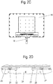
- the blocking element comprises a slot 23 on which a widening 22 is formed at the end.
- the slot 23 engages a web 21 which is rectangular in cross-section and is blocked by the walls on the slot against rotational movement.
- the web 21 is non-rotatably connected to the axle 18 or is formed integrally with it.
- the ridge 21 on the left in Figure 2D is non-rotatably connected to the axle 20 or formed integrally with it.
- the filter device 1 is shown in a position in which the door 12 has been moved in order to open an opening 13 for the plug-in chamber 5 on the right-hand side.
- the door 12 is moved via the handle element 15, with which the blocking element is also moved at the same time.
- a filter element 8 can be inserted, the geometry of the plug-in chamber 5 on the right-hand side being designed so that only a specific filter element 8 can be inserted, for example all filter elements 8 of the same geometry, which then each form a coarse filter.
- the closure element 19 can also be opened on the left side. This is due to the fact that the blocking element was moved with a plate 24 so that the web 21 on the axis 20 is no longer arranged in the area of the slot 23, but in the area of the widening 22.
- the widening 22 has a greater width in Longitudinal direction of the slot 23 than the slot 23, so that the web 21 can be rotated together with the axis 20 in order to open the closure element 19.
- the filter element 8 ′ in the dispensing chamber 6 can optionally be pulled out.
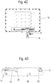
- the door 12 is closed and inserted into the Figures 4A and 4B position shown moves.
- the door 12 closes the opening 13 to the plug-in chamber 5 on the right-hand side, but releases an opening 14 to the plug-in chamber 5 on the left-hand side for a filter element 8 '.
- the blocking element was also displaced, so that the web 21, which is connected to the axis 18 or formed integrally, is now arranged in the widening 22, so that the closure element 17 is now around the axis 18 can be pivoted.
- a filter element 8 can now be removed from the dispensing chamber 6.
- the filter element 8 to be changed arranged in the flow channel 4 can slide downwards, so that the filter element 8 in the plug-in chamber 5 can slide down into the flow channel 4.
- the filter element 8 located in the flow channel 4 is pressed against a stop by the air flow to be cleaned, in particular when external air is sucked in through the open discharge chamber 6.
- the filter element 8 is then shifted in the flow channel and the filter element 8 in the plug-in chamber 5 only when the closure element 17 is closed, so that a negative pressure builds up in the output chamber 6, which causes the filter element 8 to detach from the flow channel 4.
- a displacement of the filter elements 8 can optionally also be supported or stimulated by mechanical means.
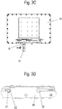
- the door 12 can then be moved into the left end position shown in FIG Figure 3B is shown. In this position, the left insertion chamber 5 is closed and a passage from the insertion chamber 5 to the flow channel 4 is opened.
- the closure element 19 must be opened in order to remove the filter element 8 ′ from the dispensing chamber 6.
- a cover 32 can be inserted into the respective filter element 8 or 8 ′, which cover can be stored on the frame 9.
- the door 12 is shown, which can be moved together with a cover 27.
- the cover 27 has an opening 28 and can thus selectively open or close a passage between an insertion chamber 5 and the flow channel 4.
- the width of the opening 28 is made so wide that all of the filter elements 8 or 8 ′ can slide through the opening 28.
- a front area is also designed as a blocking element, in which the slots 23 with the end-side widening 22 are recessed.
- the insertion chamber 5 is always closed towards the flow channel 4.
- the cover 27 covers the opening to the flow channel 4, so that only a small proportion of external air can be sucked in.
- the door 12 can be inserted into the in Figure 4B
- the position shown can be pivoted, whereby the opening between the plug-in chamber 5 and the flow channel 4 is released, since the opening 28 is then located under the plug-in chamber 5.
- the flow channel 4 is sealed off from the outside, however, since the door 12 is closed.
- the closure element 17 can then be opened in order to protect the filter element 8 can be taken from the dispensing chamber.
- a gap between the filter element 8 in the flow channel 4 and the discharge chamber 6 can be dimensioned so small that only a small amount of external air is sucked in when the filter element 8 is removed, but this leads to negligible pressure fluctuations and does not affect the production process.
- a projection is formed on the handle element 15 as a marking element 26, so that the user can see more easily whether the door is arranged in a central closed position or in one of the two lateral open positions. Furthermore, markings for identifying the individual steps for changing the filter elements 8, 8 'can be provided.
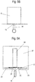
- a filter element 8 which has a filter surface 30, for example a sieve, a fabric, a perforated grid or a fleece material, the filter surface 30 being surrounded by a frame 31.
- Guide means for example grooves, are formed on the frame 31 in order to be able to cover the filter surface 30.
- a filter cake that has deposited on the filter surface 30 can be covered by the cover 32 so that when the filter element 8 is removed from the output chamber 6, no particles are sucked in by the external air which then enters the flow channel 4.
- a rotating part 34 of a latching or locking mechanism is provided on the cover 32. After the cover 32 has been pushed onto the filter element 8, the cover 32 can be locked or latched onto the filter element 8 via the rotating part 34, in order to then pull the unit of filter element 8 and cover 32 out of the dispensing chamber 6 by means of a grip element 33 on the cover 32 .
- the rotating part 34 can be designed, for example, as a bayonet lock which can be inserted in a first position into an opening on the filter element 8 and then effects a locking by rotating it through 90 °.
- the cover 32 is arranged on the filter element 8, and it can be seen that the cover 32 is surrounded on the edge side by the frame 31. As a result, the filter element 8 is largely sealed.
- the cover 32 is plate-shaped and can be made of sheet metal or plastic, for example a transparent plastic, so that the inner area of the filter element 8 remains visible.
- the cover 32 comprises an angled portion 35 on which the rotating part 34 is rotatably mounted and on which the grip element 33 is fixed.
- the cover 32 can be designed in one or more parts.
- FIG 7C a section through the filter element 8 is shown, and it can be seen that a groove 36 is formed on opposite sides, into which an edge of the plate-shaped cover 32 can be pushed. At the end face, the cover 32 can then be locked to the frame 31 via the rotating part 34.
- each filter element 8 comprises an opening 80 on the frame 31 which can be brought into engagement with the rotating part 34 on the cover 32.
- Other locking mechanisms or latching mechanisms can optionally also be used in order to produce a detachable connection between the cover 32 and a filter element 8 or 8 '.
- the filter device 1 has two shafts arranged one behind the other in the direction of flow, each shaft having an insertion chamber 5, a chamber in the flow channel 4 and an output chamber 6.
- Guide means for the filter elements 8, 8 ' can be provided on each shaft.
- the door 12 is designed to be displaceable, while the closure elements 17 and 19 are pivotably mounted. It is of course also possible to also design the door 12 to be pivotable; in particular, instead of the one-piece door, a multi-piece door with different leaves can be provided. In addition, the closure elements 17 and 19 can also be designed to be displaceable instead of pivotable.
Landscapes
- Chemical & Material Sciences (AREA)
- Chemical Kinetics & Catalysis (AREA)
- Health & Medical Sciences (AREA)
- Engineering & Computer Science (AREA)
- Environmental & Geological Engineering (AREA)
- Toxicology (AREA)
- Filtering Of Dispersed Particles In Gases (AREA)
Applications Claiming Priority (1)
| Application Number | Priority Date | Filing Date | Title |
|---|---|---|---|
| DE102020110081.7A DE102020110081B4 (de) | 2020-04-09 | 2020-04-09 | Filtervorrichtung |
Publications (3)
| Publication Number | Publication Date |
|---|---|
| EP3892353A2 true EP3892353A2 (fr) | 2021-10-13 |
| EP3892353A3 EP3892353A3 (fr) | 2021-11-10 |
| EP3892353B1 EP3892353B1 (fr) | 2022-11-30 |
Family
ID=75203216
Family Applications (1)
| Application Number | Title | Priority Date | Filing Date |
|---|---|---|---|
| EP21164606.2A Active EP3892353B1 (fr) | 2020-04-09 | 2021-03-24 | Elementes filtrant |
Country Status (3)
| Country | Link |
|---|---|
| US (1) | US11731070B2 (fr) |
| EP (1) | EP3892353B1 (fr) |
| DE (1) | DE102020110081B4 (fr) |
Cited By (1)
| Publication number | Priority date | Publication date | Assignee | Title |
|---|---|---|---|---|
| CN118807352A (zh) * | 2024-09-05 | 2024-10-22 | 湖北安鼎安全环保科技有限公司 | 一种化工安全生产降尘设备 |
Citations (2)
| Publication number | Priority date | Publication date | Assignee | Title |
|---|---|---|---|---|
| DE2802369A1 (de) | 1978-01-20 | 1979-07-26 | Ltg Lufttechnische Gmbh | Filtervorrichtung zum filtern von durch staub und faserabfaelle verunreinigter luft |
| DE9101692U1 (de) | 1991-02-14 | 1991-05-02 | Bürcher, Friedrich, 8029 Sauerlach | Lüftungskanalelement zur Einbeziehung in einen Luftkanal |
Family Cites Families (16)
| Publication number | Priority date | Publication date | Assignee | Title |
|---|---|---|---|---|
| US3354616A (en) * | 1964-11-20 | 1967-11-28 | Saint Gobain Nucleaire | Method and apparatus for loading and unloading a filter for radioactive gases |
| US4124361A (en) * | 1977-05-11 | 1978-11-07 | American Air Filter Company, Inc. | Sealing device for filter cells |
| US4251245A (en) | 1979-12-12 | 1981-02-17 | Mine Safety Appliances Company | Side loading filter apparatus |
| US4497642A (en) | 1982-07-07 | 1985-02-05 | United Kingdom Atomic Energy Authority | Filter assembly |
| US5837040A (en) * | 1996-09-09 | 1998-11-17 | International Decontamination Systems Llc | Room air decontamination device |
| FR2781550B1 (fr) * | 1998-07-27 | 2000-10-06 | Soc Et Et De Const Aero Navale | Procede de changement d'une cartouche filtrante montee dans un conduit d'ecoulement d'un fluide et agencement pour la mise en oeuvre du procede |
| US6676721B1 (en) | 2000-06-02 | 2004-01-13 | Donaldson Company, Inc. | Multistage air cleaner including pulse cleaning system |
| US7186290B2 (en) * | 2004-01-08 | 2007-03-06 | Carrier Corporation | Filter system with automatic media refresh |
| US7332012B2 (en) | 2004-07-21 | 2008-02-19 | Aaf-Mcquay Inc. | Multi-stage filtering apparatus |
| US8721753B2 (en) * | 2010-05-11 | 2014-05-13 | Bha Altair, Llc | Method and apparatus for an air filter cartridge replacement assembly |
| DE102013015630A1 (de) | 2013-09-19 | 2015-03-19 | Daimler Ag | Luftfilter für eine Belüftungseinrichtung eines Kraftwagens und Verfahren zu dessen Einbau |
| DE202016001034U1 (de) * | 2016-02-18 | 2016-04-27 | Norbert Heckmann | Filtervorrichtung für Gase, insbesondere für mit Farbnebel belastete Abluft |
| KR101749177B1 (ko) * | 2016-10-05 | 2017-06-21 | (주)씨앤지테크 | 입자상 또는 가스상 오염물질 제거용 교환형 흡착 및 재생 장치 |
| DE102017007498A1 (de) | 2017-08-08 | 2019-02-14 | Daimler Ag | Filterelement für einen Luftfilter eines Kraftwagens und Luftfilter |
| DE102018008122A1 (de) * | 2018-10-13 | 2020-04-16 | Oerlikon Textile Gmbh & Co. Kg | Verfahren und Vorrichtung zur Filterung einer verunreinigten Luft |
| DE102020110082A1 (de) * | 2020-04-09 | 2021-10-14 | Lufttechnik Gransee GmbH | Filtervorrichtung und Verfahren zum Wechseln eines Filterelementes |
-
2020
- 2020-04-09 DE DE102020110081.7A patent/DE102020110081B4/de active Active
-
2021
- 2021-03-24 EP EP21164606.2A patent/EP3892353B1/fr active Active
- 2021-04-08 US US17/225,258 patent/US11731070B2/en active Active
Patent Citations (2)
| Publication number | Priority date | Publication date | Assignee | Title |
|---|---|---|---|---|
| DE2802369A1 (de) | 1978-01-20 | 1979-07-26 | Ltg Lufttechnische Gmbh | Filtervorrichtung zum filtern von durch staub und faserabfaelle verunreinigter luft |
| DE9101692U1 (de) | 1991-02-14 | 1991-05-02 | Bürcher, Friedrich, 8029 Sauerlach | Lüftungskanalelement zur Einbeziehung in einen Luftkanal |
Cited By (1)
| Publication number | Priority date | Publication date | Assignee | Title |
|---|---|---|---|---|
| CN118807352A (zh) * | 2024-09-05 | 2024-10-22 | 湖北安鼎安全环保科技有限公司 | 一种化工安全生产降尘设备 |
Also Published As
| Publication number | Publication date |
|---|---|
| DE102020110081A1 (de) | 2021-10-14 |
| DE102020110081B4 (de) | 2025-06-26 |
| EP3892353B1 (fr) | 2022-11-30 |
| US20210316244A1 (en) | 2021-10-14 |
| EP3892353A3 (fr) | 2021-11-10 |
| US11731070B2 (en) | 2023-08-22 |
Similar Documents
| Publication | Publication Date | Title |
|---|---|---|
| DE3911153C2 (fr) | ||
| EP1878484B1 (fr) | Dispositif de passage d'air | |
| EP1890043B1 (fr) | Dispositif de passage d'air doté d'une accessibilité améliorée de l'élément filtrant | |
| DE102008031156A1 (de) | Beduftungsvorrichtung, insbesondere für ein Kraftfahrzeug | |
| DE10038882B4 (de) | Vorrichtung zum Ausgeben einer gemischten Mehrkomponentenmasse, insbesondere für zahnärztliche Zwecke | |
| EP3456495B1 (fr) | Appareil de travail portatif | |
| EP3892354B1 (fr) | Dispositif filtrant et procédé de remplacement d'un élément de filtre | |
| DE2623133A1 (de) | Filter zum trennen hoeherer dichte von material geringerer dichte | |
| EP3892353B1 (fr) | Elementes filtrant | |
| DE4037287A1 (de) | Auslass | |
| DE10026451A1 (de) | Flüssigkeitsfilter | |
| DE3901663A1 (de) | Vorrichtung zum filtern, insbesondere zum ausfiltern von staub aus einem gasstrom | |
| EP0289874B1 (fr) | Dispositif pour aspirer et filtrer de l'air chargé des poussières et/ou des fibres en suspension dans les métiers de filature | |
| DE3304441C2 (fr) | ||
| DE202013100346U1 (de) | Rückspülbarer Flüssigkeitsfilter | |
| EP0032207A1 (fr) | Aération réglable à coulisse | |
| DE10258526A1 (de) | Filtereinrichtung | |
| WO2009052911A1 (fr) | Filtre d'habitacle destiné à un système de chauffage ou de climatisation de véhicule motorisé | |
| DE4105867C2 (de) | Filtereinrichtung für flüssigen Kunststoff führende Druckleitungen | |
| DE19809375A1 (de) | Austauschbares Filter | |
| DE2834643C2 (fr) | ||
| DE102008011763A1 (de) | Filtereinrichtung für eine Textilmaschine | |
| DE3212892A1 (de) | Verfahren zum selbsttaetigen reinigen eines flaechenfilters und selbstreinigende filtereinrichtung | |
| EP3838676A1 (fr) | Unité de fermeture pour un compartiment de dépôt, compartiment de dépôt | |
| DE3426012A1 (de) | Vorrichtung zum entfernen des faserpflugs von einem sieb |
Legal Events
| Date | Code | Title | Description |
|---|---|---|---|
| PUAI | Public reference made under article 153(3) epc to a published international application that has entered the european phase |
Free format text: ORIGINAL CODE: 0009012 |
|
| STAA | Information on the status of an ep patent application or granted ep patent |
Free format text: STATUS: THE APPLICATION HAS BEEN PUBLISHED |
|
| PUAL | Search report despatched |
Free format text: ORIGINAL CODE: 0009013 |
|
| AK | Designated contracting states |
Kind code of ref document: A2 Designated state(s): AL AT BE BG CH CY CZ DE DK EE ES FI FR GB GR HR HU IE IS IT LI LT LU LV MC MK MT NL NO PL PT RO RS SE SI SK SM TR |
|
| AK | Designated contracting states |
Kind code of ref document: A3 Designated state(s): AL AT BE BG CH CY CZ DE DK EE ES FI FR GB GR HR HU IE IS IT LI LT LU LV MC MK MT NL NO PL PT RO RS SE SI SK SM TR |
|
| RIC1 | Information provided on ipc code assigned before grant |
Ipc: B01D 46/10 20060101ALI20211007BHEP Ipc: B01D 46/00 20060101AFI20211007BHEP |
|
| STAA | Information on the status of an ep patent application or granted ep patent |
Free format text: STATUS: REQUEST FOR EXAMINATION WAS MADE |
|
| 17P | Request for examination filed |
Effective date: 20220407 |
|
| RBV | Designated contracting states (corrected) |
Designated state(s): AL AT BE BG CH CY CZ DE DK EE ES FI FR GB GR HR HU IE IS IT LI LT LU LV MC MK MT NL NO PL PT RO RS SE SI SK SM TR |
|
| GRAP | Despatch of communication of intention to grant a patent |
Free format text: ORIGINAL CODE: EPIDOSNIGR1 |
|
| STAA | Information on the status of an ep patent application or granted ep patent |
Free format text: STATUS: GRANT OF PATENT IS INTENDED |
|
| INTG | Intention to grant announced |
Effective date: 20220804 |
|
| RIN1 | Information on inventor provided before grant (corrected) |
Inventor name: DIE WEITEREN ERFINDER HABEN AUF IHR RECHT VERZICHTET, ALS SOLCHE BEKANNT GEMACHT ZU WERDEN. Inventor name: DITTSCHER, SONJA Inventor name: KNOEDLER, FRANK Inventor name: PETERSEN, HAUKE Inventor name: CLAUSSEN, ERNST Inventor name: RICKERTS, STEPHAN |
|
| GRAS | Grant fee paid |
Free format text: ORIGINAL CODE: EPIDOSNIGR3 |
|
| RAP3 | Party data changed (applicant data changed or rights of an application transferred) |
Owner name: OERLIKON TEXTILE GMBH & CO. KG Owner name: LUFTTECHNIK GRANSEE GMBH |
|
| GRAA | (expected) grant |
Free format text: ORIGINAL CODE: 0009210 |
|
| STAA | Information on the status of an ep patent application or granted ep patent |
Free format text: STATUS: THE PATENT HAS BEEN GRANTED |
|
| AK | Designated contracting states |
Kind code of ref document: B1 Designated state(s): AL AT BE BG CH CY CZ DE DK EE ES FI FR GB GR HR HU IE IS IT LI LT LU LV MC MK MT NL NO PL PT RO RS SE SI SK SM TR |
|
| REG | Reference to a national code |
Ref country code: CH Ref legal event code: EP Ref country code: GB Ref legal event code: FG4D Free format text: NOT ENGLISH |
|
| REG | Reference to a national code |
Ref country code: AT Ref legal event code: REF Ref document number: 1534226 Country of ref document: AT Kind code of ref document: T Effective date: 20221215 Ref country code: DE Ref legal event code: R096 Ref document number: 502021000280 Country of ref document: DE |
|
| REG | Reference to a national code |
Ref country code: IE Ref legal event code: FG4D Free format text: LANGUAGE OF EP DOCUMENT: GERMAN |
|
| REG | Reference to a national code |
Ref country code: LT Ref legal event code: MG9D |
|
| REG | Reference to a national code |
Ref country code: NL Ref legal event code: MP Effective date: 20221130 |
|
| PG25 | Lapsed in a contracting state [announced via postgrant information from national office to epo] |
Ref country code: SE Free format text: LAPSE BECAUSE OF FAILURE TO SUBMIT A TRANSLATION OF THE DESCRIPTION OR TO PAY THE FEE WITHIN THE PRESCRIBED TIME-LIMIT Effective date: 20221130 Ref country code: PT Free format text: LAPSE BECAUSE OF FAILURE TO SUBMIT A TRANSLATION OF THE DESCRIPTION OR TO PAY THE FEE WITHIN THE PRESCRIBED TIME-LIMIT Effective date: 20230331 Ref country code: NO Free format text: LAPSE BECAUSE OF FAILURE TO SUBMIT A TRANSLATION OF THE DESCRIPTION OR TO PAY THE FEE WITHIN THE PRESCRIBED TIME-LIMIT Effective date: 20230228 Ref country code: LT Free format text: LAPSE BECAUSE OF FAILURE TO SUBMIT A TRANSLATION OF THE DESCRIPTION OR TO PAY THE FEE WITHIN THE PRESCRIBED TIME-LIMIT Effective date: 20221130 Ref country code: FI Free format text: LAPSE BECAUSE OF FAILURE TO SUBMIT A TRANSLATION OF THE DESCRIPTION OR TO PAY THE FEE WITHIN THE PRESCRIBED TIME-LIMIT Effective date: 20221130 Ref country code: ES Free format text: LAPSE BECAUSE OF FAILURE TO SUBMIT A TRANSLATION OF THE DESCRIPTION OR TO PAY THE FEE WITHIN THE PRESCRIBED TIME-LIMIT Effective date: 20221130 |
|
| PG25 | Lapsed in a contracting state [announced via postgrant information from national office to epo] |
Ref country code: RS Free format text: LAPSE BECAUSE OF FAILURE TO SUBMIT A TRANSLATION OF THE DESCRIPTION OR TO PAY THE FEE WITHIN THE PRESCRIBED TIME-LIMIT Effective date: 20221130 Ref country code: PL Free format text: LAPSE BECAUSE OF FAILURE TO SUBMIT A TRANSLATION OF THE DESCRIPTION OR TO PAY THE FEE WITHIN THE PRESCRIBED TIME-LIMIT Effective date: 20221130 Ref country code: LV Free format text: LAPSE BECAUSE OF FAILURE TO SUBMIT A TRANSLATION OF THE DESCRIPTION OR TO PAY THE FEE WITHIN THE PRESCRIBED TIME-LIMIT Effective date: 20221130 Ref country code: IS Free format text: LAPSE BECAUSE OF FAILURE TO SUBMIT A TRANSLATION OF THE DESCRIPTION OR TO PAY THE FEE WITHIN THE PRESCRIBED TIME-LIMIT Effective date: 20230330 Ref country code: HR Free format text: LAPSE BECAUSE OF FAILURE TO SUBMIT A TRANSLATION OF THE DESCRIPTION OR TO PAY THE FEE WITHIN THE PRESCRIBED TIME-LIMIT Effective date: 20221130 |
|
| PG25 | Lapsed in a contracting state [announced via postgrant information from national office to epo] |
Ref country code: NL Free format text: LAPSE BECAUSE OF FAILURE TO SUBMIT A TRANSLATION OF THE DESCRIPTION OR TO PAY THE FEE WITHIN THE PRESCRIBED TIME-LIMIT Effective date: 20221130 |
|
| PG25 | Lapsed in a contracting state [announced via postgrant information from national office to epo] |
Ref country code: SM Free format text: LAPSE BECAUSE OF FAILURE TO SUBMIT A TRANSLATION OF THE DESCRIPTION OR TO PAY THE FEE WITHIN THE PRESCRIBED TIME-LIMIT Effective date: 20221130 Ref country code: RO Free format text: LAPSE BECAUSE OF FAILURE TO SUBMIT A TRANSLATION OF THE DESCRIPTION OR TO PAY THE FEE WITHIN THE PRESCRIBED TIME-LIMIT Effective date: 20221130 Ref country code: EE Free format text: LAPSE BECAUSE OF FAILURE TO SUBMIT A TRANSLATION OF THE DESCRIPTION OR TO PAY THE FEE WITHIN THE PRESCRIBED TIME-LIMIT Effective date: 20221130 Ref country code: DK Free format text: LAPSE BECAUSE OF FAILURE TO SUBMIT A TRANSLATION OF THE DESCRIPTION OR TO PAY THE FEE WITHIN THE PRESCRIBED TIME-LIMIT Effective date: 20221130 Ref country code: CZ Free format text: LAPSE BECAUSE OF FAILURE TO SUBMIT A TRANSLATION OF THE DESCRIPTION OR TO PAY THE FEE WITHIN THE PRESCRIBED TIME-LIMIT Effective date: 20221130 |
|
| PG25 | Lapsed in a contracting state [announced via postgrant information from national office to epo] |
Ref country code: SK Free format text: LAPSE BECAUSE OF FAILURE TO SUBMIT A TRANSLATION OF THE DESCRIPTION OR TO PAY THE FEE WITHIN THE PRESCRIBED TIME-LIMIT Effective date: 20221130 Ref country code: AL Free format text: LAPSE BECAUSE OF FAILURE TO SUBMIT A TRANSLATION OF THE DESCRIPTION OR TO PAY THE FEE WITHIN THE PRESCRIBED TIME-LIMIT Effective date: 20221130 |
|
| REG | Reference to a national code |
Ref country code: DE Ref legal event code: R097 Ref document number: 502021000280 Country of ref document: DE |
|
| PLBE | No opposition filed within time limit |
Free format text: ORIGINAL CODE: 0009261 |
|
| STAA | Information on the status of an ep patent application or granted ep patent |
Free format text: STATUS: NO OPPOSITION FILED WITHIN TIME LIMIT |
|
| PG25 | Lapsed in a contracting state [announced via postgrant information from national office to epo] |
Ref country code: MC Free format text: LAPSE BECAUSE OF FAILURE TO SUBMIT A TRANSLATION OF THE DESCRIPTION OR TO PAY THE FEE WITHIN THE PRESCRIBED TIME-LIMIT Effective date: 20221130 |
|
| 26N | No opposition filed |
Effective date: 20230831 |
|
| PG25 | Lapsed in a contracting state [announced via postgrant information from national office to epo] |
Ref country code: SI Free format text: LAPSE BECAUSE OF FAILURE TO SUBMIT A TRANSLATION OF THE DESCRIPTION OR TO PAY THE FEE WITHIN THE PRESCRIBED TIME-LIMIT Effective date: 20221130 |
|
| PG25 | Lapsed in a contracting state [announced via postgrant information from national office to epo] |
Ref country code: LU Free format text: LAPSE BECAUSE OF NON-PAYMENT OF DUE FEES Effective date: 20230324 |
|
| REG | Reference to a national code |
Ref country code: IE Ref legal event code: MM4A |
|
| PG25 | Lapsed in a contracting state [announced via postgrant information from national office to epo] |
Ref country code: IE Free format text: LAPSE BECAUSE OF NON-PAYMENT OF DUE FEES Effective date: 20230324 Ref country code: FR Free format text: LAPSE BECAUSE OF NON-PAYMENT OF DUE FEES Effective date: 20230331 |
|
| PG25 | Lapsed in a contracting state [announced via postgrant information from national office to epo] |
Ref country code: IT Free format text: LAPSE BECAUSE OF FAILURE TO SUBMIT A TRANSLATION OF THE DESCRIPTION OR TO PAY THE FEE WITHIN THE PRESCRIBED TIME-LIMIT Effective date: 20221130 |
|
| PGFP | Annual fee paid to national office [announced via postgrant information from national office to epo] |
Ref country code: TR Payment date: 20240312 Year of fee payment: 4 Ref country code: BE Payment date: 20240301 Year of fee payment: 4 |
|
| PGFP | Annual fee paid to national office [announced via postgrant information from national office to epo] |
Ref country code: DE Payment date: 20240503 Year of fee payment: 4 |
|
| REG | Reference to a national code |
Ref country code: CH Ref legal event code: PL |
|
| PG25 | Lapsed in a contracting state [announced via postgrant information from national office to epo] |
Ref country code: BG Free format text: LAPSE BECAUSE OF FAILURE TO SUBMIT A TRANSLATION OF THE DESCRIPTION OR TO PAY THE FEE WITHIN THE PRESCRIBED TIME-LIMIT Effective date: 20221130 |
|
| PG25 | Lapsed in a contracting state [announced via postgrant information from national office to epo] |
Ref country code: BG Free format text: LAPSE BECAUSE OF FAILURE TO SUBMIT A TRANSLATION OF THE DESCRIPTION OR TO PAY THE FEE WITHIN THE PRESCRIBED TIME-LIMIT Effective date: 20221130 |
|
| PG25 | Lapsed in a contracting state [announced via postgrant information from national office to epo] |
Ref country code: CH Free format text: LAPSE BECAUSE OF NON-PAYMENT OF DUE FEES Effective date: 20240331 |
|
| REG | Reference to a national code |
Ref country code: BE Ref legal event code: PD Owner name: OERLIKON TEXTILE GMBH & CO. KG; DE Free format text: DETAILS ASSIGNMENT: CHANGE OF OWNER(S), ASSIGNMENT; FORMER OWNER NAME: LUFTTECHNIK GRANSEE GMBH Effective date: 20241213 |
|
| PGFP | Annual fee paid to national office [announced via postgrant information from national office to epo] |
Ref country code: AT Payment date: 20250417 Year of fee payment: 5 |
|
| PG25 | Lapsed in a contracting state [announced via postgrant information from national office to epo] |
Ref country code: CY Free format text: LAPSE BECAUSE OF FAILURE TO SUBMIT A TRANSLATION OF THE DESCRIPTION OR TO PAY THE FEE WITHIN THE PRESCRIBED TIME-LIMIT; INVALID AB INITIO Effective date: 20210324 |
|
| PG25 | Lapsed in a contracting state [announced via postgrant information from national office to epo] |
Ref country code: HU Free format text: LAPSE BECAUSE OF FAILURE TO SUBMIT A TRANSLATION OF THE DESCRIPTION OR TO PAY THE FEE WITHIN THE PRESCRIBED TIME-LIMIT; INVALID AB INITIO Effective date: 20210324 |
|
| PG25 | Lapsed in a contracting state [announced via postgrant information from national office to epo] |
Ref country code: GR Free format text: LAPSE BECAUSE OF FAILURE TO SUBMIT A TRANSLATION OF THE DESCRIPTION OR TO PAY THE FEE WITHIN THE PRESCRIBED TIME-LIMIT; INVALID AB INITIO Effective date: 20210324 |
|
| REG | Reference to a national code |
Ref country code: DE Ref legal event code: R119 Ref document number: 502021000280 Country of ref document: DE |
|
| GBPC | Gb: european patent ceased through non-payment of renewal fee |
Effective date: 20250324 |
|
| REG | Reference to a national code |
Ref country code: BE Ref legal event code: MM Effective date: 20250331 |
|
| PG25 | Lapsed in a contracting state [announced via postgrant information from national office to epo] |
Ref country code: DE Free format text: LAPSE BECAUSE OF NON-PAYMENT OF DUE FEES Effective date: 20251001 |
|
| PG25 | Lapsed in a contracting state [announced via postgrant information from national office to epo] |
Ref country code: GB Free format text: LAPSE BECAUSE OF NON-PAYMENT OF DUE FEES Effective date: 20250324 |
|
| PG25 | Lapsed in a contracting state [announced via postgrant information from national office to epo] |
Ref country code: BE Free format text: LAPSE BECAUSE OF NON-PAYMENT OF DUE FEES Effective date: 20250331 |