EP3892479B1 - Dispositif anti-dérapage pour roues - Google Patents
Dispositif anti-dérapage pour roues Download PDFInfo
- Publication number
- EP3892479B1 EP3892479B1 EP21153789.9A EP21153789A EP3892479B1 EP 3892479 B1 EP3892479 B1 EP 3892479B1 EP 21153789 A EP21153789 A EP 21153789A EP 3892479 B1 EP3892479 B1 EP 3892479B1
- Authority
- EP
- European Patent Office
- Prior art keywords
- arc
- cable
- wheel
- branch
- skid device
- Prior art date
- Legal status (The legal status is an assumption and is not a legal conclusion. Google has not performed a legal analysis and makes no representation as to the accuracy of the status listed.)
- Active
Links
Images



Classifications
-
- B—PERFORMING OPERATIONS; TRANSPORTING
- B60—VEHICLES IN GENERAL
- B60C—VEHICLE TYRES; TYRE INFLATION; TYRE CHANGING; CONNECTING VALVES TO INFLATABLE ELASTIC BODIES IN GENERAL; DEVICES OR ARRANGEMENTS RELATED TO TYRES
- B60C27/00—Non-skid devices temporarily attachable to resilient tyres or resiliently-tyred wheels
- B60C27/06—Non-skid devices temporarily attachable to resilient tyres or resiliently-tyred wheels extending over the complete circumference of the tread, e.g. made of chains or cables
- B60C27/062—Non-skid devices temporarily attachable to resilient tyres or resiliently-tyred wheels extending over the complete circumference of the tread, e.g. made of chains or cables provided with fastening means
- B60C27/066—Non-skid devices temporarily attachable to resilient tyres or resiliently-tyred wheels extending over the complete circumference of the tread, e.g. made of chains or cables provided with fastening means acting on the sidewall of the tyre
-
- B—PERFORMING OPERATIONS; TRANSPORTING
- B60—VEHICLES IN GENERAL
- B60C—VEHICLE TYRES; TYRE INFLATION; TYRE CHANGING; CONNECTING VALVES TO INFLATABLE ELASTIC BODIES IN GENERAL; DEVICES OR ARRANGEMENTS RELATED TO TYRES
- B60C27/00—Non-skid devices temporarily attachable to resilient tyres or resiliently-tyred wheels
- B60C27/06—Non-skid devices temporarily attachable to resilient tyres or resiliently-tyred wheels extending over the complete circumference of the tread, e.g. made of chains or cables
-
- B—PERFORMING OPERATIONS; TRANSPORTING
- B60—VEHICLES IN GENERAL
- B60C—VEHICLE TYRES; TYRE INFLATION; TYRE CHANGING; CONNECTING VALVES TO INFLATABLE ELASTIC BODIES IN GENERAL; DEVICES OR ARRANGEMENTS RELATED TO TYRES
- B60C27/00—Non-skid devices temporarily attachable to resilient tyres or resiliently-tyred wheels
- B60C27/06—Non-skid devices temporarily attachable to resilient tyres or resiliently-tyred wheels extending over the complete circumference of the tread, e.g. made of chains or cables
- B60C27/10—Non-skid devices temporarily attachable to resilient tyres or resiliently-tyred wheels extending over the complete circumference of the tread, e.g. made of chains or cables having tensioning means
- B60C27/12—Non-skid devices temporarily attachable to resilient tyres or resiliently-tyred wheels extending over the complete circumference of the tread, e.g. made of chains or cables having tensioning means resilient pretension
Definitions
- the present invention relates to an anti-skid device, such as a snow chain mountable on a wheel of a vehicle. More particularly, the anti-skid device according to the invention has features that allow facilitated mounting and dismantling on the wheel.
- Snow chains When a vehicle is on a road surface covered by snow, sleet or ice, its tyres do not have a good grip and dangerous skidding and sliding of the vehicle can occur. To avoid these problems, it is common to use anti-skid devices, commonly called snow chains. Snow chains, normally fitted on the vehicle's driving wheels, cutting into the snow and/or ice deposited on the road surface, increase friction on the tread of the tyres and allow a good hold of the vehicle's tyres.
- a traditional snow chain generally consists of two lateral elements (chains, flexible cables, steel wires, ropes or the like), which in use conditions are closed in a ring on the inner side and on the outer side of the wheel respectively, and which here below will be called the inner and outer ring respectively.
- These lateral elements are connected by a series of chain sections, variously arranged, to achieve friction on the tread, the whole being completed by a device for tensioning said elements, known by the name of tensioner.
- the chain sections arranged on the tread generally have a rhomboid configuration, with elements arranged diagonally to provide grip in both longitudinal and transverse directions.
- FR522878A describes a device formed by a single metal ring element, in a single piece or in two arcs, which is arranged on the inner side of the tyre, and by a series of chain sections connected thereto.
- US 1336363 also lacking a tensioner, describes an anti-skid device comprising two ring elements to be applied onto the sides of the wheels and a plurality of chain sections arranged on either side of the ring elements so that, once in operation, the chain sections cover the tread of the tyre of the wheel to which the device is applied.
- the ring elements are rigid and provide for complicated assembly, however effective for the time.
- the arc elements are joined together and attached to the wheel by four bolts placed at 90° from each other and extend between the wheel spokes.
- WO2004/035332 A1 provides a folding anti-skid device for car tyres.
- the device when installed around a tyre, is formed by two ring elements and is provided with a plurality of anti-skid pads that are arranged on the tread at regular intervals.
- the two ring elements in this case are formed by a series of segments hinged together and have, at staggered intervals, connectors to connect the snow pads, forming in this way a folding 'accordion' anti-skid device.
- snow chains are generally fitted by placing the chain on the wheel, subsequently turning the wheel by moving the vehicle and then repositioning the snow chain and securing it around the wheel.
- an anti-skid device comprising a fixing element suitable for being positioned substantially on one side of a wheel of a vehicle.
- the fixing element is in the form of two semi-arcs held together by an extendable element, generally a cable inserted therein, i.e., made to enter from a first end of the first semi-arc and made to exit from a second end of the second semi-arc.
- the fixing element comprises an open area or gap between the other ends of the two semi-arcs, which nevertheless remain connected by the passage of the extendable cable.
- the ends of the cable, exiting the unconnected ends of the two semi-arcs, are directed, by means of a bypass or bridge element arranged transversely to the fixing element and designed to cover the width of the tread, towards one end of a tensioning device in elongated form.
- a tensioning device in elongated form.
- a mesh of chain sections is attached, which in turn is connected in various points of the fixing element to semi-arcs.
- the fixing element can be widened during assembly in such a way as to be fitted on the inner side of the wheel (i.e., the side directed towards the centre of the vehicle), with the cable that remains at the outer side, where the tensioning device is also located.
- This tensioning device is designed to impart a force to the extended element and allows the anti-skid device to move from a position wherein it is almost mounted, before the vehicle is started, with the extendable element in an extended condition, to a position wherein it is ready for use, after starting, with the extendable element tensioned so as to bring the ends of the half-arcs which had previously been moved apart closer together and fix the fixing element on the inner side of the wheel.
- the anti-skid device has a self-assembling function.
- Snow chains such as those described although integrating a self-assembly function, still have several disadvantages, among which the presence of inconvenient tensioning elements, which remain visible and which are applied causing interference with structural parts of the wheel, with the consequence of causing damage to elements such as rims, a situation which is very irksome in the case of alloy rims. This is mainly due to the fact that the fixing element on the outer side of the wheel consists of chain sections which require the aforementioned tensioning elements and which themselves go to rub against the rim.
- the object of the present invention is therefore to provide an anti-skid device for wheels which allows the disadvantages of the prior art to be overcome.
- an object of the present invention is to provide an anti-skid device which makes the operations of mounting and dismantling on vehicle wheels simpler, with uniform tensioning of the fixing components.
- Another object of the present invention is to provide an anti-skid device that is flexible, light to transport and economical.
- a further object is to provide an anti-skid device which does not detract from the aesthetic appearance of the wheel to which it is applied, and which reduces to a minimum contacts with the structural parts of the wheel, more particularly the rim.
- the present invention relates to an anti-skid device for a wheel of a vehicle, comprising a first arc-shaped element suitable for being mounted at a first side of said wheel, whose ends define a first gap; a second arc-shaped element suitable for being mounted at a second side of said wheel, whose ends define a second gap; a bridge element suitable for connecting said first and second arc-shaped elements in such a way as to distance them on planes substantially parallel one to the other, with the gaps arranged substantially with identical radial orientation; an anti-skid element between the first and second arc elements suitable, in the mounted device condition, for being arranged on the surface of the tread of said wheel; wherein the arrangement of said bridge element divides the first arc element into a first branch and a second branch and said second arc element into a first branch and into a second branch and there is provided an extendable cable having a first and a second end; the first end of said cable is fixed in a point of the first branch of the first arc element
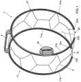
- Fig. 1 shows a schematic representation of an anti-skid device, denoted as a whole by reference numeral 1, when it is not applied to a wheel.
- the anti-skid device 1 is formed substantially by a first arc fixing element 11 and a second arc fixing element 21, joined by a bridge element 4.
- the arc fixing elements 11 and 21 are suitable, once mounted, to be arranged on the inner and outer sides of the wheel respectively, resting on the tyre sides.
- a series of chain sections, forming a mesh 5, are arranged between the arc elements 11 and 21, so as to cover the tread surface when the device 1 is mounted on a wheel.
- the arc elements 11, 21 have the feature of allowing a certain degree of flexibility: by exerting a moving away force on the ends, the arc element can be widened, and then return to the normal condition once the stress has ended.
- the first arc element 11 terminates in two ends 12a, 12b delimiting a first gap 18.
- the second arc element 21 terminates in two ends 22a, 22b delimiting a second gap 28.
- the providing of the bridge element 4 effectively divides the first arc element 11 into a first branch 11a and into a second branch 11b and, in the same way, divides the second arc element 21 into a first branch 21a and into a second branch 21b.
- the two gaps 18, 28 are at an almost identical radial orientation.
- the arc elements 11, 21 can be provided as a single part or in two separate parts, corresponding to the respective branches 11a, 11b and 21a, 21b.
- a spring element 29 can be provided between the two ends 21a and 21b to limit the moving away of the branches of the second arc element 21.
- the arc elements 11, 21 act as a guide for an extendable element of elongated shape, more particularly a cable or a rope 7.
- a tubular sheath can be provided, arranged around the arc elements 11,21, running externally or internally thereto, inside of which the cable 7 is slidable.
- the provision of the extendable element or cable 7 makes it possible to widen the arc elements even to a considerable extent in order to position them on the sides of the wheel in a pre-assembled condition. By applying tension to the cable 7, the arc elements are in turn tensioned in order to attach to the wheel.
- the extendable cable 7 is arranged in the manner described here below.
- One end of the cable 7 is fixed in a point of the first branch 11a of the first arc element 11 and is made to slide along it as far as the first end 12a, where it meets the first gap 18.
- the cable goes beyond the first gap 18 to reach the second branch 11b entering from the second end 12b of the first arc 11.
- the cable 7 Having travelled along the entire branch 11b, the cable 7 reaches the bridge element 4 from which it is directed towards the first branch 21a of the second arc element 21.
- the cable 7 goes beyond the second gap 28 and enters the second branch 21b from the end 22b.
- the cable 7 travels along a length thereof until it is collected by a tensioning device or tensioner 30, suitable for tensioning the cable 7 and in this way bringing the arc elements 11 and 21 into a closed condition, bringing back together the ends 12a and 12b, 22a and 22b when the anti-skid device is mounted on the wheel.
- this tensioning device 30 is placed in a substantially central position of the second branch 21b.
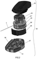
- the tensioning device 30 has an internal structure such as that shown in Fig. 2 , showing in an exploded view the various parts which make it up.
- the tensioning device which can be considered functionally in itself known, is formed by a base 31 in which is housed a pulley 34 provided with external teeth around which the extendable cable 7 is wound.
- the external teeth 36' of the pulley 34 are apt to engage with a first non-return pawl 36 and a second non-return element 37 is apt to engage with internal teeth 37' of the pulley, functioning as a sort of double ratchet drive.
- the pulley is only allowed to rotate in one direction, (the clockwise one with reference to the drawings), movement in the opposite direction being prevented.
- the pawl 36 has a non-return function, allowing only the winding of the cable and not its unwinding.
- the non-return element 37 engaging with the corresponding teeth 37', allows the pulley 34 to rotate only in one direction, opposite to that allowed by the pawl 36.
- the non-return element 37 allows rotation only in an anticlockwise direction, allowing the unwinding of the cable 7.
- the non-return element 37 can be brought into engagement with the toothed pulley 34 to allow distancing of the ends of the flexible arc elements 11 and 21, with consequent extension of the cable 7. This movement is caused manually by physically pushing the ends of the flexible elements apart.
- the winding of the cable 7 around the pulley takes place instead due to the return force of a spiral spring 33 mounted integrally to the pulley 34.
- the spiral spring 33 When the cable 7 is in an extended position, the spiral spring 33 generates a return force which tends to bring it back into the originally wound position. Rewinding of the cable is prevented as long as the non-return element 37 is engaged with the teeth 37' of the pulley 34. When this element 37 is disengaged, the pulley can rotate in a clockwise direction, allowing the cable to be rewound and bringing the arc elements 11 and 21 into closure, this rotation not being prevented by the pawl 36 given what is mentioned above.
- the tensioning device 30 is provided with a selector 35 in order to move the pawl 36 and the non-return element 37, alternately, from the engagement position to the disengagement position.
- the elements just described are contained in the base 31 and covered by a closure cover 32.
- An anti-skid device 1 as just described is thus capable of being mounted on a wheel in a simple and direct manner.
- FIGs 3 to 8 a sequence of actions to be carried out for successful mounting of the device is now described.
- the ends of the first arc element 11 are distanced so as to widen the branches 11a, 11b ( Fig. 3 ).
- the operation of widening of the branches of the arc element 11 causes the gap 18 to be of a greater width and the cable 7 to be very loosened.
- the device 1 can at this point be "fitted" on the wheel, with the first arc element 11 made to pass over the wheel so as to be on its inner side, i.e. the side turned towards the axis of the vehicle.
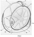
- the situation is the one shown in Fig. 4 , with the mesh 5 arranged on the tread and the second arc element 21 arranged on the outer side of the wheel, more particularly on the sides of the tyre.
- the branches of the first arc element 11 are still in a widened position and a portion of cable 7 in the gap 18 of the first arc element 11 is located on the outer side of the wheel.
- the situation is the one shown in Fig. 5 with part of the cable 7 still on the outside of the wheel.
- the tensioning device 30 draws in cable 7 making the first arc element 11 tighten on the inner side of the wheel ( Fig. 7 ).
- the chain is now in a practically mounted condition.
- the cable will move from the outer to the inner side of the wheel, fully tensioning the device and therefore fixing the arc elements 11 and 21 to the tyre sides.
- a quick and automatic mounting of the snow chain is carried out.
- the advantages of the anti-skid device according to the invention appear clear. More particularly, in the embodiment of the arc elements in a single part, these are substantially rigid, but endowed with a certain flexibility, so as to allow an extremely easy and secure mounting on the tyre, avoiding rubbing with the rim, since there are practically no parts in contact with the same.
Landscapes
- Engineering & Computer Science (AREA)
- Mechanical Engineering (AREA)
- Handcart (AREA)
- Bridges Or Land Bridges (AREA)
- Refuge Islands, Traffic Blockers, Or Guard Fence (AREA)
- Braking Arrangements (AREA)
- Regulating Braking Force (AREA)
Claims (9)
- Dispositif antidérapage pour roues (1) pour une roue d'un véhicule, comprenant :un premier élément arqué (11) apte à être monté d'un premier côté de ladite roue et dont les extrémités (12a, 12b) définissent un premier intervalle (18) ;un second élément arqué (21) apte à être monté d'un second côté de ladite roue et dont les extrémités (22a, 22b) définissent un second intervalle (28) ;un élément pont (4) apte à connecter lesdits premier et second éléments arqués (11, 21) de manière à les espacer sur des plans substantiellement parallèles l'un à l'autre, les intervalles (18, 28) étant disposés avec une orientation radiale substantiellement identique ;un élément antidérapage (5) entre les premier et second éléments arqués (11, 21) apte, en état monté du dispositif (1), à être disposé sur la surface de la bande de roulement de ladite roue ;l'agencement dudit élément pont (4) divisant le premier élément arqué (11) en une première branche (11a) et en une seconde branche (11b) et le second élément arqué (21) en une première branche (21a) et en une seconde branche (21b),caractérisé en cequ'un câble extensible (7) doté d'une première et d'une seconde extrémité est prévu ;que la première extrémité dudit câble (7) est fixée à un point de la première branche (11a) du premier élément arqué (2) ;que le câble (7) va au-delà du premier intervalle (18), suit toute la longueur de la seconde branche (11b) du premier élément arqué (11) et, par l'intermédiaire dudit élément pont (4), atteint le second élément arqué (21) ; qu'il parcourt toute la longueur de la seconde branche (21a) du second élément arqué (21), va au-delà du second intervalle (28) et atteint un dispositif de tension (30) prévu à une position de la seconde branche (21b) à laquelle il est fixé par sa seconde extrémité ;que ledit dispositif de tension (30) est apte à tendre le câble extensible (7) une fois que le dispositif antidérapage (1) a été monté sur la roue, en réduisant lesdits premier et second intervalles (18, 28) afin de fixer lesdits éléments arqués (11, 21) sur les côtés intérieur et extérieur de la roue en se plaçant lui-même sur les côtés du pneu.
- Dispositif antidérapage (1) selon la revendication 1, dans lequel ledit câble (7) passe par l'intérieur ou par l'extérieur jusqu'auxdits éléments arqués (11, 21).
- Dispositif antidérapage (1) selon la revendication 2, dans lequel ledit câble (7) passe dans des gaines tubulaires.
- Dispositif antidérapage (1) selon l'une quelconque des revendications précédentes, dans lequel chacun desdits éléments arqués (11,21) est réalisé en une seule pièce ou en deux branches séparées (11a, 11b ; 21a, 21b).
- Dispositif antidérapage (1) selon l'une quelconque des revendications précédentes, dans lequel lesdits éléments arqués (11, 21) sont composés d'acier.
- Dispositif antidérapage (1) selon l'une quelconque des revendications précédentes, dans lequel un élément à ressort (29) est placé dans ledit intervalle (28) entre les extrémités (22a, 22b) du second élément arqué (21) afin de maintenir l'arc ouvert pendant les opérations de montage.
- Dispositif antidérapage (1) selon l'une quelconque des revendications précédentes, dans lequel ledit élément antidérapage (5) est un maillon de sections de chaîne.
- Dispositif antidérapage (1) selon l'une quelconque des revendications précédentes, dans lequel ledit dispositif de tension (30) comprend une poulie dentée (34) autour de laquelle le câble (7) s'enroule et se déroule, un ressort à spirale (33) étant associé à ladite poulie (34) afin de ramener le câble (7) dans une position d'enroulement.
- Dispositif antidérapage (1) selon la revendication 6, comprenant en outre un cliquet antiretour (36) apte à former un entraînement à cliquet avec ladite poulie dentée (34) en permettant, une fois engagé, la rotation de la poulie (34) dans le sens d'enroulement du câble et bloquant sa rotation dans le sens opposé.
Applications Claiming Priority (1)
| Application Number | Priority Date | Filing Date | Title |
|---|---|---|---|
| IT102020000007273A IT202000007273A1 (it) | 2020-04-06 | 2020-04-06 | Dispositivo antislittamento per ruote |
Publications (2)
| Publication Number | Publication Date |
|---|---|
| EP3892479A1 EP3892479A1 (fr) | 2021-10-13 |
| EP3892479B1 true EP3892479B1 (fr) | 2022-01-19 |
Family
ID=71452553
Family Applications (1)
| Application Number | Title | Priority Date | Filing Date |
|---|---|---|---|
| EP21153789.9A Active EP3892479B1 (fr) | 2020-04-06 | 2021-01-27 | Dispositif anti-dérapage pour roues |
Country Status (3)
| Country | Link |
|---|---|
| EP (1) | EP3892479B1 (fr) |
| JP (1) | JP7631038B2 (fr) |
| IT (1) | IT202000007273A1 (fr) |
Family Cites Families (10)
| Publication number | Priority date | Publication date | Assignee | Title |
|---|---|---|---|---|
| US1336363A (en) * | 1920-04-06 | Antiskzdding armob | ||
| FR522878A (fr) * | 1917-01-02 | 1921-08-08 | Alexandre Deutsch | Un nouvel antidérapant applicable sur les bandages des roues des camions automobiles et autres véhicules de poids lourds de l'armée |
| US1912481A (en) * | 1932-11-28 | 1933-06-06 | Hubbard Edward | Nonskid attachment |
| JPH04238704A (ja) * | 1991-01-08 | 1992-08-26 | Minoru Takeuchi | タイヤチェーン |
| AU2003206216A1 (en) * | 2002-10-21 | 2004-05-04 | Kyu-Han Park | Foldable snow chain for car tires |
| JP2006044639A (ja) * | 2004-06-29 | 2006-02-16 | Koizumi:Kk | タイヤ用滑り止め装置 |
| AT510451B1 (de) | 2010-10-14 | 2012-09-15 | Pewag Schneeketten Gmbh & Co Kg | Spannvorrichtung für eine gleitschutzkette |
| EP2489528B1 (fr) | 2011-02-16 | 2015-08-05 | Thule Sweden AB | Dispositif anti-dérapage pour roue |
| JP6234203B2 (ja) | 2013-12-11 | 2017-11-22 | 株式会社カーメイト | タイヤ滑り止め装置 |
| DE102016217232A1 (de) | 2016-09-09 | 2018-03-15 | Rud Ketten Rieger & Dietz Gmbh U. Co. Kg | Spannvorrichtung für eine Gleitschutz- oder Reifenschutzvorrichtung eines Fahrzeugreifens mit einem Handauszug |
-
2020
- 2020-04-06 IT IT102020000007273A patent/IT202000007273A1/it unknown
-
2021
- 2021-01-27 EP EP21153789.9A patent/EP3892479B1/fr active Active
- 2021-03-05 JP JP2021034977A patent/JP7631038B2/ja active Active
Also Published As
| Publication number | Publication date |
|---|---|
| JP7631038B2 (ja) | 2025-02-18 |
| IT202000007273A1 (it) | 2021-10-06 |
| EP3892479A1 (fr) | 2021-10-13 |
| JP2021165121A (ja) | 2021-10-14 |
Similar Documents
| Publication | Publication Date | Title |
|---|---|---|
| US7036542B2 (en) | Nonskid device for the wheels of vehicles | |
| US8720509B2 (en) | Tension device for a nonskid chain | |
| EP2050591B1 (fr) | Dispositif anti-dérapage avec montage depuis le côté extérieur | |
| US6915825B1 (en) | Self-tensioning tire cable chain system | |
| CA2249845C (fr) | Chaine d'adherence pour pneus de roues en tandem | |
| US5236025A (en) | Diagonal tire chains with side cable fasteners | |
| RU2666982C1 (ru) | Усовершенствованный колесный диск | |
| JPH06102407B2 (ja) | 対角線状タイヤチェーン | |
| US4066112A (en) | Automobile-tire snow chains | |
| EP3892479A1 (fr) | Dispositif anti-dérapage pour roues | |
| CN103347714A (zh) | 用于车轮的防滑装置和用于安装该防滑装置的方法 | |
| EP1859969A1 (fr) | Ceinture élastique anti-neige et verglas à crampons pour pneumatique d'automobile à montage facile et rapide | |
| EP3736144B1 (fr) | Dispositif antidérapage avec montage externe pour grandes roues | |
| EP1752320A1 (fr) | Chaîne anti-dérapante avec système de montage élastique | |
| EP1072448B1 (fr) | Tendeur automatique pour chaínes à neige | |
| JP6013765B2 (ja) | 共通で被覆されており牽引手段に似た保持部材を有するタイヤチェーン | |
| JP2844246B2 (ja) | タイヤ滑り止め装置の締結装置 | |
| JP4920676B2 (ja) | 弾性締結手段を含むタイヤチェーン取付システム | |
| RU2523541C1 (ru) | Противопробуксовочное устройство | |
| KR200278767Y1 (ko) | 자동차용 스노우 체인 | |
| EP1160102A2 (fr) | Crochet de liaison pour relier des éléments de chaínes de neige | |
| JPH0431112A (ja) | 滑り止め装置 | |
| RU162111U1 (ru) | Противобуксовочное устройство для колеса | |
| KR19980013887U (ko) | 타이어의 미끄럼 방지 장치 | |
| IE43122B1 (en) | Anti-skid device for vehicle tyres |
Legal Events
| Date | Code | Title | Description |
|---|---|---|---|
| PUAI | Public reference made under article 153(3) epc to a published international application that has entered the european phase |
Free format text: ORIGINAL CODE: 0009012 |
|
| STAA | Information on the status of an ep patent application or granted ep patent |
Free format text: STATUS: REQUEST FOR EXAMINATION WAS MADE |
|
| 17P | Request for examination filed |
Effective date: 20210719 |
|
| AK | Designated contracting states |
Kind code of ref document: A1 Designated state(s): AL AT BE BG CH CY CZ DE DK EE ES FI FR GB GR HR HU IE IS IT LI LT LU LV MC MK MT NL NO PL PT RO RS SE SI SK SM TR |
|
| GRAP | Despatch of communication of intention to grant a patent |
Free format text: ORIGINAL CODE: EPIDOSNIGR1 |
|
| STAA | Information on the status of an ep patent application or granted ep patent |
Free format text: STATUS: GRANT OF PATENT IS INTENDED |
|
| INTG | Intention to grant announced |
Effective date: 20211029 |
|
| GRAS | Grant fee paid |
Free format text: ORIGINAL CODE: EPIDOSNIGR3 |
|
| GRAA | (expected) grant |
Free format text: ORIGINAL CODE: 0009210 |
|
| STAA | Information on the status of an ep patent application or granted ep patent |
Free format text: STATUS: THE PATENT HAS BEEN GRANTED |
|
| AK | Designated contracting states |
Kind code of ref document: B1 Designated state(s): AL AT BE BG CH CY CZ DE DK EE ES FI FR GB GR HR HU IE IS IT LI LT LU LV MC MK MT NL NO PL PT RO RS SE SI SK SM TR |
|
| REG | Reference to a national code |
Ref country code: GB Ref legal event code: FG4D |
|
| REG | Reference to a national code |
Ref country code: CH Ref legal event code: EP |
|
| REG | Reference to a national code |
Ref country code: DE Ref legal event code: R096 Ref document number: 602021000005 Country of ref document: DE |
|
| REG | Reference to a national code |
Ref country code: AT Ref legal event code: REF Ref document number: 1463597 Country of ref document: AT Kind code of ref document: T Effective date: 20220215 |
|
| REG | Reference to a national code |
Ref country code: IE Ref legal event code: FG4D |
|
| REG | Reference to a national code |
Ref country code: LT Ref legal event code: MG9D |
|
| REG | Reference to a national code |
Ref country code: NL Ref legal event code: MP Effective date: 20220119 |
|
| PG25 | Lapsed in a contracting state [announced via postgrant information from national office to epo] |
Ref country code: NL Free format text: LAPSE BECAUSE OF FAILURE TO SUBMIT A TRANSLATION OF THE DESCRIPTION OR TO PAY THE FEE WITHIN THE PRESCRIBED TIME-LIMIT Effective date: 20220119 |
|
| PG25 | Lapsed in a contracting state [announced via postgrant information from national office to epo] |
Ref country code: SE Free format text: LAPSE BECAUSE OF FAILURE TO SUBMIT A TRANSLATION OF THE DESCRIPTION OR TO PAY THE FEE WITHIN THE PRESCRIBED TIME-LIMIT Effective date: 20220119 Ref country code: RS Free format text: LAPSE BECAUSE OF FAILURE TO SUBMIT A TRANSLATION OF THE DESCRIPTION OR TO PAY THE FEE WITHIN THE PRESCRIBED TIME-LIMIT Effective date: 20220119 Ref country code: PT Free format text: LAPSE BECAUSE OF FAILURE TO SUBMIT A TRANSLATION OF THE DESCRIPTION OR TO PAY THE FEE WITHIN THE PRESCRIBED TIME-LIMIT Effective date: 20220519 Ref country code: NO Free format text: LAPSE BECAUSE OF FAILURE TO SUBMIT A TRANSLATION OF THE DESCRIPTION OR TO PAY THE FEE WITHIN THE PRESCRIBED TIME-LIMIT Effective date: 20220419 Ref country code: LT Free format text: LAPSE BECAUSE OF FAILURE TO SUBMIT A TRANSLATION OF THE DESCRIPTION OR TO PAY THE FEE WITHIN THE PRESCRIBED TIME-LIMIT Effective date: 20220119 Ref country code: HR Free format text: LAPSE BECAUSE OF FAILURE TO SUBMIT A TRANSLATION OF THE DESCRIPTION OR TO PAY THE FEE WITHIN THE PRESCRIBED TIME-LIMIT Effective date: 20220119 Ref country code: ES Free format text: LAPSE BECAUSE OF FAILURE TO SUBMIT A TRANSLATION OF THE DESCRIPTION OR TO PAY THE FEE WITHIN THE PRESCRIBED TIME-LIMIT Effective date: 20220119 Ref country code: BG Free format text: LAPSE BECAUSE OF FAILURE TO SUBMIT A TRANSLATION OF THE DESCRIPTION OR TO PAY THE FEE WITHIN THE PRESCRIBED TIME-LIMIT Effective date: 20220419 |
|
| PG25 | Lapsed in a contracting state [announced via postgrant information from national office to epo] |
Ref country code: PL Free format text: LAPSE BECAUSE OF FAILURE TO SUBMIT A TRANSLATION OF THE DESCRIPTION OR TO PAY THE FEE WITHIN THE PRESCRIBED TIME-LIMIT Effective date: 20220119 Ref country code: LV Free format text: LAPSE BECAUSE OF FAILURE TO SUBMIT A TRANSLATION OF THE DESCRIPTION OR TO PAY THE FEE WITHIN THE PRESCRIBED TIME-LIMIT Effective date: 20220119 Ref country code: GR Free format text: LAPSE BECAUSE OF FAILURE TO SUBMIT A TRANSLATION OF THE DESCRIPTION OR TO PAY THE FEE WITHIN THE PRESCRIBED TIME-LIMIT Effective date: 20220420 Ref country code: FI Free format text: LAPSE BECAUSE OF FAILURE TO SUBMIT A TRANSLATION OF THE DESCRIPTION OR TO PAY THE FEE WITHIN THE PRESCRIBED TIME-LIMIT Effective date: 20220119 |
|
| PG25 | Lapsed in a contracting state [announced via postgrant information from national office to epo] |
Ref country code: IS Free format text: LAPSE BECAUSE OF FAILURE TO SUBMIT A TRANSLATION OF THE DESCRIPTION OR TO PAY THE FEE WITHIN THE PRESCRIBED TIME-LIMIT Effective date: 20220519 |
|
| REG | Reference to a national code |
Ref country code: DE Ref legal event code: R097 Ref document number: 602021000005 Country of ref document: DE |
|
| PG25 | Lapsed in a contracting state [announced via postgrant information from national office to epo] |
Ref country code: SM Free format text: LAPSE BECAUSE OF FAILURE TO SUBMIT A TRANSLATION OF THE DESCRIPTION OR TO PAY THE FEE WITHIN THE PRESCRIBED TIME-LIMIT Effective date: 20220119 Ref country code: SK Free format text: LAPSE BECAUSE OF FAILURE TO SUBMIT A TRANSLATION OF THE DESCRIPTION OR TO PAY THE FEE WITHIN THE PRESCRIBED TIME-LIMIT Effective date: 20220119 Ref country code: RO Free format text: LAPSE BECAUSE OF FAILURE TO SUBMIT A TRANSLATION OF THE DESCRIPTION OR TO PAY THE FEE WITHIN THE PRESCRIBED TIME-LIMIT Effective date: 20220119 Ref country code: MC Free format text: LAPSE BECAUSE OF FAILURE TO SUBMIT A TRANSLATION OF THE DESCRIPTION OR TO PAY THE FEE WITHIN THE PRESCRIBED TIME-LIMIT Effective date: 20220119 Ref country code: EE Free format text: LAPSE BECAUSE OF FAILURE TO SUBMIT A TRANSLATION OF THE DESCRIPTION OR TO PAY THE FEE WITHIN THE PRESCRIBED TIME-LIMIT Effective date: 20220119 Ref country code: DK Free format text: LAPSE BECAUSE OF FAILURE TO SUBMIT A TRANSLATION OF THE DESCRIPTION OR TO PAY THE FEE WITHIN THE PRESCRIBED TIME-LIMIT Effective date: 20220119 Ref country code: CZ Free format text: LAPSE BECAUSE OF FAILURE TO SUBMIT A TRANSLATION OF THE DESCRIPTION OR TO PAY THE FEE WITHIN THE PRESCRIBED TIME-LIMIT Effective date: 20220119 |
|
| PLBE | No opposition filed within time limit |
Free format text: ORIGINAL CODE: 0009261 |
|
| STAA | Information on the status of an ep patent application or granted ep patent |
Free format text: STATUS: NO OPPOSITION FILED WITHIN TIME LIMIT |
|
| PG25 | Lapsed in a contracting state [announced via postgrant information from national office to epo] |
Ref country code: AL Free format text: LAPSE BECAUSE OF FAILURE TO SUBMIT A TRANSLATION OF THE DESCRIPTION OR TO PAY THE FEE WITHIN THE PRESCRIBED TIME-LIMIT Effective date: 20220119 |
|
| 26N | No opposition filed |
Effective date: 20221020 |
|
| REG | Reference to a national code |
Ref country code: AT Ref legal event code: UEP Ref document number: 1463597 Country of ref document: AT Kind code of ref document: T Effective date: 20220119 |
|
| PG25 | Lapsed in a contracting state [announced via postgrant information from national office to epo] |
Ref country code: LU Free format text: LAPSE BECAUSE OF NON-PAYMENT OF DUE FEES Effective date: 20230127 |
|
| REG | Reference to a national code |
Ref country code: BE Ref legal event code: MM Effective date: 20230131 |
|
| PG25 | Lapsed in a contracting state [announced via postgrant information from national office to epo] |
Ref country code: BE Free format text: LAPSE BECAUSE OF NON-PAYMENT OF DUE FEES Effective date: 20230131 |
|
| PG25 | Lapsed in a contracting state [announced via postgrant information from national office to epo] |
Ref country code: IE Free format text: LAPSE BECAUSE OF NON-PAYMENT OF DUE FEES Effective date: 20230127 |
|
| PG25 | Lapsed in a contracting state [announced via postgrant information from national office to epo] |
Ref country code: HU Free format text: LAPSE BECAUSE OF FAILURE TO SUBMIT A TRANSLATION OF THE DESCRIPTION OR TO PAY THE FEE WITHIN THE PRESCRIBED TIME-LIMIT; INVALID AB INITIO Effective date: 20210127 |
|
| PG25 | Lapsed in a contracting state [announced via postgrant information from national office to epo] |
Ref country code: TR Free format text: LAPSE BECAUSE OF FAILURE TO SUBMIT A TRANSLATION OF THE DESCRIPTION OR TO PAY THE FEE WITHIN THE PRESCRIBED TIME-LIMIT Effective date: 20220119 |
|
| PG25 | Lapsed in a contracting state [announced via postgrant information from national office to epo] |
Ref country code: CY Free format text: LAPSE BECAUSE OF FAILURE TO SUBMIT A TRANSLATION OF THE DESCRIPTION OR TO PAY THE FEE WITHIN THE PRESCRIBED TIME-LIMIT; INVALID AB INITIO Effective date: 20210127 |
|
| GBPC | Gb: european patent ceased through non-payment of renewal fee |
Effective date: 20250127 |
|
| PG25 | Lapsed in a contracting state [announced via postgrant information from national office to epo] |
Ref country code: GB Free format text: LAPSE BECAUSE OF NON-PAYMENT OF DUE FEES Effective date: 20250127 |
|
| PGFP | Annual fee paid to national office [announced via postgrant information from national office to epo] |
Ref country code: FR Payment date: 20251223 Year of fee payment: 6 |
|
| REG | Reference to a national code |
Ref country code: CH Ref legal event code: U11 Free format text: ST27 STATUS EVENT CODE: U-0-0-U10-U11 (AS PROVIDED BY THE NATIONAL OFFICE) Effective date: 20260201 |
|
| PG25 | Lapsed in a contracting state [announced via postgrant information from national office to epo] |
Ref country code: SI Free format text: LAPSE BECAUSE OF FAILURE TO SUBMIT A TRANSLATION OF THE DESCRIPTION OR TO PAY THE FEE WITHIN THE PRESCRIBED TIME-LIMIT Effective date: 20220119 |
|
| PGFP | Annual fee paid to national office [announced via postgrant information from national office to epo] |
Ref country code: DE Payment date: 20260128 Year of fee payment: 6 |
|
| PGFP | Annual fee paid to national office [announced via postgrant information from national office to epo] |
Ref country code: AT Payment date: 20260128 Year of fee payment: 6 |
|
| PGFP | Annual fee paid to national office [announced via postgrant information from national office to epo] |
Ref country code: IT Payment date: 20251216 Year of fee payment: 6 |
|
| PGFP | Annual fee paid to national office [announced via postgrant information from national office to epo] |
Ref country code: CH Payment date: 20260201 Year of fee payment: 6 |