EP3892497B1 - Lichtmodul - Google Patents
Lichtmodul Download PDFInfo
- Publication number
- EP3892497B1 EP3892497B1 EP21165988.3A EP21165988A EP3892497B1 EP 3892497 B1 EP3892497 B1 EP 3892497B1 EP 21165988 A EP21165988 A EP 21165988A EP 3892497 B1 EP3892497 B1 EP 3892497B1
- Authority
- EP
- European Patent Office
- Prior art keywords
- light
- unit
- main
- light unit
- emission surface
- Prior art date
- Legal status (The legal status is an assumption and is not a legal conclusion. Google has not performed a legal analysis and makes no representation as to the accuracy of the status listed.)
- Active
Links
Images



Classifications
-
- B—PERFORMING OPERATIONS; TRANSPORTING
- B60—VEHICLES IN GENERAL
- B60Q—ARRANGEMENT OF SIGNALLING OR LIGHTING DEVICES, THE MOUNTING OR SUPPORTING THEREOF OR CIRCUITS THEREFOR, FOR VEHICLES IN GENERAL
- B60Q1/00—Arrangement of optical signalling or lighting devices, the mounting or supporting thereof or circuits therefor
- B60Q1/0029—Spatial arrangement
- B60Q1/0041—Spatial arrangement of several lamps in relation to each other
- B60Q1/0058—Stacked, i.e. one lamp located behind the other in the optical axis direction
-
- B—PERFORMING OPERATIONS; TRANSPORTING
- B60—VEHICLES IN GENERAL
- B60Q—ARRANGEMENT OF SIGNALLING OR LIGHTING DEVICES, THE MOUNTING OR SUPPORTING THEREOF OR CIRCUITS THEREFOR, FOR VEHICLES IN GENERAL
- B60Q1/00—Arrangement of optical signalling or lighting devices, the mounting or supporting thereof or circuits therefor
- B60Q1/26—Arrangement of optical signalling or lighting devices, the mounting or supporting thereof or circuits therefor the devices being primarily intended to indicate the vehicle, or parts thereof, or to give signals, to other traffic
- B60Q1/46—Arrangement of optical signalling or lighting devices, the mounting or supporting thereof or circuits therefor the devices being primarily intended to indicate the vehicle, or parts thereof, or to give signals, to other traffic for giving flashing caution signals during drive, other than signalling change of direction, e.g. flashing the headlights or hazard lights
-
- F—MECHANICAL ENGINEERING; LIGHTING; HEATING; WEAPONS; BLASTING
- F21—LIGHTING
- F21S—NON-PORTABLE LIGHTING DEVICES; SYSTEMS THEREOF; VEHICLE LIGHTING DEVICES SPECIALLY ADAPTED FOR VEHICLE EXTERIORS
- F21S41/00—Illuminating devices specially adapted for vehicle exteriors, e.g. headlamps
- F21S41/20—Illuminating devices specially adapted for vehicle exteriors, e.g. headlamps characterised by refractors, transparent cover plates, light guides or filters
- F21S41/24—Light guides
-
- F—MECHANICAL ENGINEERING; LIGHTING; HEATING; WEAPONS; BLASTING
- F21—LIGHTING
- F21S—NON-PORTABLE LIGHTING DEVICES; SYSTEMS THEREOF; VEHICLE LIGHTING DEVICES SPECIALLY ADAPTED FOR VEHICLE EXTERIORS
- F21S41/00—Illuminating devices specially adapted for vehicle exteriors, e.g. headlamps
- F21S41/60—Illuminating devices specially adapted for vehicle exteriors, e.g. headlamps characterised by a variable light distribution
- F21S41/63—Illuminating devices specially adapted for vehicle exteriors, e.g. headlamps characterised by a variable light distribution by acting on refractors, filters or transparent cover plates
- F21S41/635—Illuminating devices specially adapted for vehicle exteriors, e.g. headlamps characterised by a variable light distribution by acting on refractors, filters or transparent cover plates by moving refractors, filters or transparent cover plates
-
- F—MECHANICAL ENGINEERING; LIGHTING; HEATING; WEAPONS; BLASTING
- F21—LIGHTING
- F21S—NON-PORTABLE LIGHTING DEVICES; SYSTEMS THEREOF; VEHICLE LIGHTING DEVICES SPECIALLY ADAPTED FOR VEHICLE EXTERIORS
- F21S43/00—Signalling devices specially adapted for vehicle exteriors, e.g. brake lamps, direction indicator lights or reversing lights
- F21S43/10—Signalling devices specially adapted for vehicle exteriors, e.g. brake lamps, direction indicator lights or reversing lights characterised by the light source
- F21S43/13—Signalling devices specially adapted for vehicle exteriors, e.g. brake lamps, direction indicator lights or reversing lights characterised by the light source characterised by the type of light source
- F21S43/14—Light emitting diodes [LED]
-
- F—MECHANICAL ENGINEERING; LIGHTING; HEATING; WEAPONS; BLASTING
- F21—LIGHTING
- F21S—NON-PORTABLE LIGHTING DEVICES; SYSTEMS THEREOF; VEHICLE LIGHTING DEVICES SPECIALLY ADAPTED FOR VEHICLE EXTERIORS
- F21S43/00—Signalling devices specially adapted for vehicle exteriors, e.g. brake lamps, direction indicator lights or reversing lights
- F21S43/10—Signalling devices specially adapted for vehicle exteriors, e.g. brake lamps, direction indicator lights or reversing lights characterised by the light source
- F21S43/13—Signalling devices specially adapted for vehicle exteriors, e.g. brake lamps, direction indicator lights or reversing lights characterised by the light source characterised by the type of light source
- F21S43/14—Light emitting diodes [LED]
- F21S43/145—Surface emitters, e.g. organic light emitting diodes [OLED]
-
- F—MECHANICAL ENGINEERING; LIGHTING; HEATING; WEAPONS; BLASTING
- F21—LIGHTING
- F21S—NON-PORTABLE LIGHTING DEVICES; SYSTEMS THEREOF; VEHICLE LIGHTING DEVICES SPECIALLY ADAPTED FOR VEHICLE EXTERIORS
- F21S43/00—Signalling devices specially adapted for vehicle exteriors, e.g. brake lamps, direction indicator lights or reversing lights
- F21S43/20—Signalling devices specially adapted for vehicle exteriors, e.g. brake lamps, direction indicator lights or reversing lights characterised by refractors, transparent cover plates, light guides or filters
- F21S43/235—Light guides
- F21S43/236—Light guides characterised by the shape of the light guide
- F21S43/237—Light guides characterised by the shape of the light guide rod-shaped
-
- F—MECHANICAL ENGINEERING; LIGHTING; HEATING; WEAPONS; BLASTING
- F21—LIGHTING
- F21S—NON-PORTABLE LIGHTING DEVICES; SYSTEMS THEREOF; VEHICLE LIGHTING DEVICES SPECIALLY ADAPTED FOR VEHICLE EXTERIORS
- F21S43/00—Signalling devices specially adapted for vehicle exteriors, e.g. brake lamps, direction indicator lights or reversing lights
- F21S43/20—Signalling devices specially adapted for vehicle exteriors, e.g. brake lamps, direction indicator lights or reversing lights characterised by refractors, transparent cover plates, light guides or filters
- F21S43/235—Light guides
- F21S43/236—Light guides characterised by the shape of the light guide
- F21S43/239—Light guides characterised by the shape of the light guide plate-shaped
-
- F—MECHANICAL ENGINEERING; LIGHTING; HEATING; WEAPONS; BLASTING
- F21—LIGHTING
- F21S—NON-PORTABLE LIGHTING DEVICES; SYSTEMS THEREOF; VEHICLE LIGHTING DEVICES SPECIALLY ADAPTED FOR VEHICLE EXTERIORS
- F21S43/00—Signalling devices specially adapted for vehicle exteriors, e.g. brake lamps, direction indicator lights or reversing lights
- F21S43/20—Signalling devices specially adapted for vehicle exteriors, e.g. brake lamps, direction indicator lights or reversing lights characterised by refractors, transparent cover plates, light guides or filters
- F21S43/235—Light guides
- F21S43/242—Light guides characterised by the emission area
- F21S43/245—Light guides characterised by the emission area emitting light from one or more of its major surfaces
-
- F—MECHANICAL ENGINEERING; LIGHTING; HEATING; WEAPONS; BLASTING
- F21—LIGHTING
- F21W—INDEXING SCHEME ASSOCIATED WITH SUBCLASSES F21K, F21L, F21S and F21V, RELATING TO USES OR APPLICATIONS OF LIGHTING DEVICES OR SYSTEMS
- F21W2102/00—Exterior vehicle lighting devices for illuminating purposes
- F21W2102/10—Arrangement or contour of the emitted light
- F21W2102/13—Arrangement or contour of the emitted light for high-beam region or low-beam region
-
- F—MECHANICAL ENGINEERING; LIGHTING; HEATING; WEAPONS; BLASTING
- F21—LIGHTING
- F21W—INDEXING SCHEME ASSOCIATED WITH SUBCLASSES F21K, F21L, F21S and F21V, RELATING TO USES OR APPLICATIONS OF LIGHTING DEVICES OR SYSTEMS
- F21W2102/00—Exterior vehicle lighting devices for illuminating purposes
- F21W2102/10—Arrangement or contour of the emitted light
- F21W2102/17—Arrangement or contour of the emitted light for regions other than high beam or low beam
- F21W2102/19—Arrangement or contour of the emitted light for regions other than high beam or low beam for curves
-
- F—MECHANICAL ENGINEERING; LIGHTING; HEATING; WEAPONS; BLASTING
- F21—LIGHTING
- F21W—INDEXING SCHEME ASSOCIATED WITH SUBCLASSES F21K, F21L, F21S and F21V, RELATING TO USES OR APPLICATIONS OF LIGHTING DEVICES OR SYSTEMS
- F21W2103/00—Exterior vehicle lighting devices for signalling purposes
- F21W2103/55—Daytime running lights [DRL]
Definitions
- the invention relates to a light module.
- Light modules for headlights are known in which parts of the light modules have to be adjusted mechanically.
- the EP 2 703 218 A2 discloses a headlight for motor vehicles and a method for controlling the same.
- the headlight comprises a first and second lamp module, the second lamp module being arranged on the front side of the first lamp module, and a mode of the second lamp module is set to one of a first mode in which a part of the second lamp module overlaps with the first lamp module on a light travel path, and a second mode in which the second lamp module does not overlap with the first lamp module.
- Comparable is from the DE 10 2016 124 111 A1 previously known.
- a first aspect of the invention relates to a light module according to claim 1.
- the secondary light unit Since the secondary light unit emits the first main light distribution, the fact that the secondary light unit partially covers the main light unit is less critical. Rather, the requirements on the drive are reduced by the emission of the first main light distribution from the secondary light unit.
- the drive thus has to move the auxiliary light unit less quickly in the direction of the second position.
- the activation of the main light function which is mainly provided by the main light unit, is accelerated in that the first main light distribution is emitted even before the secondary light unit releases the main light unit.
- the light module provided is for the implementation of the "headlight flasher" function, which is activated by briefly switching on the high beam using the main light unit.
- the headlight flasher light is gradually replaced by the actual main beam. This allows for a gentler change, also with regard to light intensity, without reducing the actual attention-getting effect.
- the first main light distribution advantageously bridges the duration of the movement of the secondary light unit until the second main light distribution is released.
- the light module includes an additional light source for emitting a first light distribution
- the auxiliary light unit includes a light guide which includes a coupling surface for coupling the first light distribution and the emitting surface.
- An advantageous example is characterized in that the additional light source is arranged fixed to the main light unit, and the additional light source and the secondary light unit are arranged relative to one another in the first position such that the first light distribution is coupled into the light guide via the coupling surface.
- the covering of the main light unit can advantageously be bridged for a short time.
- the light guide of the secondary light unit comprises a coupling surface and the emission surface, with the coupling surface coupling at least part of the second main light distribution emitted by the emission surface of the main light unit into the light guide when the secondary light source is in the first position, so that the first Main light distribution from the emission surface of the light guide depending on the second
- Main light distribution can be emitted.
- the coupled-in light is advantageously guided around non-transparent sections of the secondary light unit, for example, in order to be coupled out at the emission surface. It is also ensured that the light color and spectral composition correspond exactly to the light of the second main light distribution. In particular, further light sources can be omitted.
- a second aspect of the invention relates to a light module according to claim 5.
- a third aspect of the description relates to a method for operating a light module for a motor vehicle headlight, the method comprising: a first step in which an activation signal is determined or received and a secondary light distribution is emitted from an emission surface of the secondary light unit by means of a secondary light unit; a second step in which, depending on the activation signal, a first main light distribution is emitted from the emission surface of the auxiliary light unit by means of the auxiliary light unit; a third step in which, by means of a drive unit, the secondary light unit is moved relative to a main light unit, starting from a first position, in which the secondary light unit at least partially covers an emission surface of the main light unit, to a second position, in which the emission surface of the main light unit is covered by the auxiliary light unit is reduced, is moved in response to the activation signal; and a fourth step in which a second main light distribution is emitted from the emission surface of the main light unit by means of the main light unit.
- An advantageous example is characterized in that the emission of the first main light distribution and the emission of the second main light distribution are activated together.
- Light module 100 for a motor vehicle headlight 102 is shown.
- An auxiliary light unit 104 is configured to emit an auxiliary light distribution N from an emission surface 106 of the auxiliary light unit 104 in a step 202, and to emit a first main light distribution H1 from the emission surface 106 of the auxiliary light unit 104 in a step 204;
- a drive unit 108 is configured to move the secondary light unit 104 relative to a main light unit 110, starting from a first position p1, in which the secondary light unit 104 at least partially covers a radiating surface 112 of the main lighting unit 110, to a second position p2, in which the covering of the radiating surface 112 of the main light unit 110 is reduced by the sub light unit 104 to move.
- the drive unit 108 includes, for example, an electric motor that introduces a drive torque into a transmission 109 .
- the transmission 109 is connected to the secondary light unit 104 in a torque-transmitting manner in order to move it.
- the main light unit 110 is configured to emit a second main light distribution H2 from the emission surface 112 of the main light unit 110 in the main emission direction HR.
- the main light function of the main light unit 110 includes, for example, the functions of high beam, low beam or a matrix light or the corresponding light distribution.
- the Auxiliary light function of the auxiliary light unit 104 includes, for example, a cornering light, a daytime running light and other light functions or the associated light distribution.
- the main light unit 110 and the secondary light unit 104 are arranged one after the other in the vehicle direction or main emission direction HR.
- the main functions low beam, high beam and matrix are arranged opposite to the main direction of emission, while the auxiliary functions or secondary functions are arranged in the main direction of emission HR.
- the auxiliary light unit 104 is mechatronically folded away or turned away. Alternatively, this movement away from the first position p1 into the second position p2 can also take place along a chosen path.
- Switching on the main light unit 110 lasts between a few milliseconds and typically 40 ms in the case of xenon bifunction modules.
- Moving the secondary light module 104 takes about 500 ms to 1000 ms, which would be too long for the headlight flasher function. Therefore, when the sub light unit 104 is turned on and when or before the sub light unit 104 starts moving away, the sub light unit 104 is operated so that the first main light distribution H1 is irradiated.
- the light module 100 is arranged inside a housing 130 which is closed with a transparent cover plate 132 .
- the control unit 120 receives the activation signal A and the deactivation signal D.
- the control unit 120 uses control signals S to control the light module according to the method steps described.
- the light module 100 includes an additional light source 302 for emitting a first light distribution.
- the secondary light unit 104 includes a light guide 204 which includes a coupling surface 402 for coupling the first light distribution and the emission surface 106 .
- the light guide 204 is mounted rotatably about an axis 404 in order to be moved back and forth between the first and the second position p1, p2.
- the secondary light unit 104 is shown in the second position and can be transferred to the first position p1 according to the arrow 406 .
- the light guide 204 of the secondary light unit 104 includes a light guide section 408 in order to guide the light coupled in from the coupling-in surface 402 in the direction of the emission surface 106 of the secondary light unit 104 .
- the additional light source 302 which can be referred to as a headlight flasher LED, lights up, for example, for a period of 1000 ms or precisely for a period of time that is required to turn or push away the auxiliary light unit 104. Then the main beam takes over the main light unit 110. Since the duty cycle of the headlight flasher function is comparatively short, the thermal easy to implement requirements. With regard to its light color and spectral composition of the emitted light, the LED of the headlight flasher function is adapted to the light color and spectral composition of the light of the main light unit 110 in such a way that the driver and oncoming traffic cannot detect any color difference.
- the additional light source 302 is in the figure 4 fixedly arranged to the main light unit 110 .
- the additional light source 302 and the auxiliary light unit 104 in the first position p1 are arranged relative to one another such that the light distribution emitted by the additional light source 302 is coupled into the light guide 204 via the coupling surface 402 .
- the light guide 204 of the secondary light unit 104 comprises a coupling surface 502 and the emission surface 106.
- the coupling surface 502 couples at least part of the second main light distribution H2 emitted by the emission surface 112 of the main light unit 110 into the light guide 204.
- This coupling and forwarding in the light guide 204 takes place in such a way that a first modified main light distribution H1 can be emitted from the emission surface 106 of the light guide 204 as a function of the second main light distribution H2.
- the coupling surface 502 arranged opposite comprises the light guide 204 reflector structures 504, which guide the coupled-in light of the second main light distribution H2 in the direction of a deflection section 506.
- the light guide 204 encloses an auxiliary function assembly of the auxiliary light unit 104 in such a way that the high beam from the light guide 204 is guided around the auxiliary function assembly.
- the deflection section 506 comprises, for example, mirrored reflector surfaces 508, 510, which guide the light from the proximal section of the light guide 204, into which the light is coupled, to the distal section of the light guide 204, in which the light is coupled out via the emission surface 106.
- the two deflection mirror coatings according to the deflection sections 508 and 510 enable a lighter design and manufacture as well as better light conduction at the moment of switching on and thus the attention effect. If the entire auxiliary light unit 104 moves upwards, less high beam arrives with the correct angle of incidence at the first deflection angle.
- the secondary light function is deactivated and the main light function is activated.
- the second main light distribution H2 is coupled into the proximal section of the light guide 204 and guided into the distal section of the light guide 204 . There the light is coupled out of the light guide 204 via the emission surface 106 in the form of the first modified main light distribution H1.
- the auxiliary light unit 104 is located at the second position p2. Light is no longer coupled into the light guide 204, which is why the first modified main light function is deactivated. The emission surface 112 is now no longer covered by the secondary light unit 104, with the result that the second main light distribution H2 provides the main light function.
- the first and second main light distributions H1, H2 provide a headlight flasher function or a high beam function.
- figure 6 shows a schematic flowchart for operating the light module 100.
- Determining or receiving 602 an activation signal A is used to activate the headlight flasher, which is carried out below. Radiating 204 the first Main light distribution H1 takes place as a function of activation signal A. Movement 206 of secondary light unit 104 out of first position p1 takes place as a function of activation signal A.
- the emission of the first main light distribution H1 and the emission of the second main light distribution H2 are activated together, for example. This means that steps 208 and 204 are executed almost in parallel.
- the separate light source 302 can be activated before the emission of the second main light distribution H2 by the main light unit 110.
- a deactivation 604 of the emission 202 of the secondary light distribution N is carried out as a function of the activation signal A, ie when the activation signal A is received or determined. If a deactivation signal D is received in step 606, the auxiliary light function is activated 608 and the previously activated main light function is at least deactivated 610 .
- the secondary light unit 104 comprises a carrier 304 and a luminescent layer 306 arranged on the carrier 304, which comprises, for example, a film-like printed circuit board with a plurality of semiconductor light sources arranged thereon.
- a carrier 304 which comprises, for example, a film-like printed circuit board with a plurality of semiconductor light sources arranged thereon.
- the carrier 304 comprises, for example, a film-like printed circuit board with a plurality of semiconductor light sources arranged thereon.
- rod light guides or plate light guides can also be used.
- the light is coupled in at one end of the rod or via a suitable central coupling and it is coupled out via the other end of the rod or with the help of decoupling elements via part of the outer surface of the light guide.
- the coupling preferably takes place via an end face of the plate light guide or by means of known coupling optics and the decoupling takes place via a further end face.
- the other embodiments mentioned can also have deflection surfaces, in which case the deflection surfaces can also be provided with prisms.
Landscapes
- Engineering & Computer Science (AREA)
- General Engineering & Computer Science (AREA)
- Physics & Mathematics (AREA)
- Microelectronics & Electronic Packaging (AREA)
- Optics & Photonics (AREA)
- Mechanical Engineering (AREA)
- Non-Portable Lighting Devices Or Systems Thereof (AREA)
- Lighting Device Outwards From Vehicle And Optical Signal (AREA)
Description
- Die Erfindung betrifft ein Lichtmodul.
- Es sind Lichtmodule für Scheinwerfer bekannt, bei denen Teile von Lichtmodulen mechanisch zu verstellen.
- Die
EP 2 703 218 A2 offenbart einen Scheinwerfer für Kraftfahrzeuge sowie ein Verfahren zur Kontrollierung desselben. Der Scheinwerfer umfasst in einer Ausführungsform dabei ein erstes und zweites Lampenmodul, wobei das zweite Lampenmodul an der Frontseite des ersten Lampenmoduls angeordnet ist, und ein Modus des zweiten Lampenmoduls auf einen von einem ersten Modus, in dem ein Teil des zweiten Lampenmoduls mit dem ersten Lampenmodul auf einem Lichtverlaufsweg überlappt, und einem zweiten Modus, in dem das zweite Lampenmodul nicht mit dem ersten Lampenmodul überlappt, eingestellt ist. - Vergleichbares ist aus der
DE 10 2016 124 111 A1 vorbekannt. - Ausgehend von diesem Stand der Technik, ist es die Aufgabe der Erfindung, ein Lichtmodul mit verstellbaren Elementen zu verbessern.
- Ein erster Aspekt der Erfindung betrifft ein Lichtmodul gemäß Anspruch 1.
- Da die Nebenlichteinheit die erste Hauptlichtverteilung abstrahlt, ist der Umstand, dass die Nebenlichteinheit die Hauptlichteinheit teilweise verdeckt weniger kritisch. Vielmehr verringern sich durch das Abstrahlen der ersten Hauptlichtverteilung von der Nebenlichteinheit die Anforderungen an den Antrieb. Der Antrieb muss somit weniger schnell die Nebenlichteinheit in Richtung der zweiten Position bewegen. Gleichzeitig wird die Aktivierung der Hauptlichtfunktion, welche hauptsächlich von der Hauptlichteinheit bereitgestellt wird, beschleunigt, indem, bereits bevor die Nebenlichteinheit die Hauptlichteinheit freigibt, die erste Hauptlichtverteilung abgestrahlt wird.
- Das bereitgestellte Lichtmodul ist für die Realisierung der Funktion "Lichthupe", die durch ein kurzzeitiges Einschalten des Fernlichts mittels der Hauptlichteinheit aktiviert wird. Während des Wegdrehens oder Wegschiebens der Nebenlichteinheit wird sukzessive das Lichthupenlicht durch das eigentliche Fernlicht ersetzt. Dadurch wird ein sanfterer Wechsel auch hinsichtlich Lichtstärke ermöglicht, ohne die eigentliche Aufmerksamkeitswirkung zu reduzieren.
- Vorteilhaft überbrückt die erste Hauptlichtverteilung die Zeitdauer der Bewegung der Nebenlichteinheit bis zur Freigabe der zweiten Hauptlichtverteilung.
- Ein vorteilhaftes Beispiel zeichnet sich dadurch aus, dass das Lichtmodul eine Zusatzlichtquelle zum Abstrahlen einer ersten Lichtverteilung umfasst, und wobei die Nebenlichteinheit einen Lichtleiter, welcher einer Einkoppelfläche zur Einkopplung der ersten Lichtverteilung und die Abstrahlfläche umfasst, umfasst.
- Ein vorteilhaftes Beispiel zeichnet sich dadurch aus, dass die Zusatzlichtquelle feststehend zu der Hauptlichteinheit angeordnet ist, und wobei die Zusatzlichtquelle und die Nebenlichteinheit in der ersten Position so zueinander angeordnet sind, dass die erste Lichtverteilung über die Einkoppelfläche in den Lichtleiter eingekoppelt wird.
- Vorteilhaft kann hierdurch kurzzeitig die Verdeckung der Hauptlichteinheit überbrückt werden.
- Ein vorteilhaftes Beispiel zeichnet sich dadurch aus, dass der Lichtleiter der Nebenlichteinheit eine Einkoppelfläche und die Abstrahlfläche umfasst, wobei die Einkoppelfläche in der ersten Position der Nebenlichtquelle wenigstens einen Teil der von der Abstrahlfläche der Hauptlichteinheit abgestrahlten zweiten Hauptlichtverteilung in den Lichtleiter einkoppelt, so dass die erste Hauptlichtverteilung von der Abstrahlfläche des Lichtleiters in Abhängigkeit von der zweiten
- Hauptlichtverteilung abstrahlbar ist.
- Vorteilhaft wird das eingekoppelte Licht beispielsweise um nicht transparente Abschnitte der Nebenlichteinheit herumgeleitet, um an der Abstrahlfläche ausgekoppelt zu werden. Auch ist sichergestellt, dass Lichtfarbe und spektrale Zusammensetzung exakt dem Licht der zweiten Hauptlichtverteilung entsprechen. Insbesondere können weitere Lichtquellen entfallen.
- Ein zweiter Aspekt der Erfindung betrifft ein Lichtmodul gemäβ Anspruch 5.
- Ein dritter, nicht erfindungsgemäßer Aspekt der Beschreibung betrifft ein Verfahren zum Betreiben eines Lichtmoduls für einen Kraftfahrzeugscheinwerfer, wobei das Verfahren umfasst: Einen ersten Schritt, in welchem ein Aktivierungssignals ermittelt oder empfangen wird und mittels einer Nebenlichteinheit eine Nebenlichtverteilung von einer Abstrahlfläche der Nebenlichteinheit abgestrahlt wird; einen zweiten Schritt, in welchem in Abhängigkeit von dem Aktivierungssignal, mittels der Nebenlichteinheit, eine erste Hauptlichtverteilung von der Abstrahlfläche der Nebenlichteinheit abgestrahlt wird; einen dritten Schritt, in welchem, mittels einer Antriebseinheit, die Nebenlichteinheit relativ zu einer Hauptlichteinheit ausgehend von einer ersten Position, in welcher die Nebenlichteinheit eine Abstrahlfläche der Hauptlichteinheit zumindest abschnittsweise überdeckt, in eine zweite Position, in welcher die Überdeckung der Abstrahlfläche der Hauptlichteinheit durch die Nebenlichteinheit reduziert ist, in Abhängigkeit von dem Aktivierungssignal bewegt wird; und einen vierten Schritt, in welchem mittels der Hauptlichteinheit eine zweite Hauptlichtverteilung von der Abstrahlfläche der Hauptlichteinheit abgestrahlt wird.
- Ein vorteilhaftes Beispiel zeichnet sich dadurch aus, dass die Abstrahlung der ersten Hauptlichtverteilung und die Abstrahlung der zweiten Hauptlichtverteilung gemeinsam aktiviert werden.
- Vorteilhaft wird dadurch ein sichtbarer Einschaltversatz minimiert.
- In der Zeichnung zeigen:
- Figur 1
- einen Kraftfahrzeugscheinwerfer mit einem Lichtmodul in schematischer Form;
- Figuren 2 und 6
- jeweils ein schematisches Ablaufdiagramm;
- Figuren 3a, 3b
- ein Beispiel des Lichtmoduls in schematischer Form;
- Figur 4
- ein weiteres Beispiel des Lichtmoduls in schematischer Form; und
- Figuren 5a bis 5c
- ein zusätzliches Beispiel des Lichtmoduls in schematischer Form.
- Zunächst wird auf die
Figuren 1 und 2 Bezug genommen. Es ist Lichtmodul 100 für einen Kraftfahrzeugscheinwerfer 102 gezeigt. - Eine Nebenlichteinheit 104 ist dazu konfiguriert, eine Nebenlichtverteilung N von einer Abstrahlfläche 106 der Nebenlichteinheit 104 in einem Schritt 202 abzustrahlen, und eine erste Hauptlichtverteilung H1 von der Abstrahlfläche 106 der Nebenlichteinheit 104 in einem Schritt 204 abzustrahlen;
- Eine Antriebseinheit 108 ist dazu konfiguriert, die Nebenlichteinheit 104 relativ zu einer Hauptlichteinheit 110 ausgehend von einer ersten Position p1, in welcher die Nebenlichteinheit 104 eine Abstrahlfläche 112 der Hauptlichteinheit 110 zumindest abschnittsweise überdeckt, in eine zweite Position p2, in welcher die Überdeckung der Abstrahlfläche 112 der Hauptlichteinheit 110 durch die Nebenlichteinheit 104 reduziert ist, zu bewegen. Die Antriebseinheit 108 umfasst beispielsweise einen Elektromotor, der ein Antriebsmoment in ein Getriebe 109 einbringt. Das Getriebe 109 ist zu einer Bewegung der Nebenlichteinheit 104 mit dieser momentübertragend verbunden.
- Die Hauptlichteinheit 110 ist dazu konfiguriert, eine zweite Hauptlichtverteilung H2 von der Abstrahlfläche 112 der Hauptlichteinheit 110 in die Hauptabstrahlrichtung HR abzustrahlen.
- Die Hauptlichtfunktion der Hauptlichteinheit 110 umfasst beispielsweise die Funktionen Fernlicht, Abblendlicht oder ein Matrixlicht bzw. die entsprechende Lichtverteilung. Die Nebenlichtfunktion der Nebenlichteinheit 104 umfasst beispielsweise ein Abbiegelicht, ein Tagfahrlicht und andere Lichtfunktionen bzw. die zugeordnete Lichtverteilung. Die Hauptlichteinheit 110 und die Nebenlichteinheit 104 sind in Fahrzeugrichtung bzw. Hauptabstrahlrichtung HR nacheinander angeordnet. Dabei sind die Hauptfunktionen Abblendlicht, Fernlicht und Matrix entgegen der Hauptabstrahlrichtung angeordnet, die Hilfsfunktionen bzw. Nebenfunktionen hingegen in Hauptabstrahlrichtung HR angeordnet. Wenn nun von Tagfahrlicht im Sinne der Nebenlichtfunktion auf Abblendlicht oder auf Fernlicht im Sinne der Hauptlichtfunktion umgeschaltet wird, so wird die Nebenlichteinheit 104 mechatronisch weggeklappt oder weggedreht. Alternativ kann dieses Wegbewegen aus der ersten Position p1 in die zweite Position p2 auch entlang einer gewählten Bahn erfolgen.
- Ein Einschalten der Hauptlichteinheit 110 dauert zwischen wenigen Millisekunden bis typischerweise 40ms bei Xenon-Bifunktionsmodulen. Das Bewegen des Nebenlichtmoduls 104 erfordert etwa 500 ms bis 1000 ms, was für die Funktion Lichthupe zu lange wäre. Deshalb wird die Nebenlichteinheit 104 beim Einschalten und beim oder vor Beginn des Wegbewegens der Nebenlichteinheit 104 so betrieben, dass die erste Hauptlichtverteilung H1 abgestrahlt wird.
- Das Lichtmodul 100 ist innerhalb eines Gehäuses 130 angeordnet, welches mit einer transparenten Abdeckscheibe 132 verschlossen ist.
- Die Steuereinheit 120 empfängt das Aktivierungssignal A und das Deaktivierungssignal D. Die Steuereinheit 120 steuert über Steuersignale S das Lichtmodul gemäß den beschriebenen Verfahrensschritten.
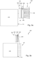
- Gemäß den
Figuren 3a und 3b umfasst das Lichtmodul 100 eine Zusatzlichtquelle 302 zum Abstrahlen einer ersten Lichtverteilung. Die Nebenlichteinheit 104 umfasst einen Lichtleiter 204, welcher eine Einkoppelfläche 402 zur Einkopplung der ersten Lichtverteilung und die Abstrahlfläche 106 umfasst. - Gemäß der
Figur 4 ist der Lichtleiter 204 um eine Achse 404 drehbar gelagert, um zwischen der ersten und der zweiten Position p1, p2 hin- und her bewegt zu werden. Gezeigt ist die Nebenlichteinheit 104 in der zweiten Position und kann gemäß dem Pfeil 406 in die erste Position p1 überführt werden. Der Lichtleiter 204 der Nebenlichteinheit 104 umfasst einen Lichtleitabschnitt 408, um das von der Einkoppelfläche 402 eingekoppelte Licht in Richtung der Abstrahlfläche 106 der Nebenlichteinheit 104 zu leiten. - Die als Lichthupen-LED bezeichenbare Zusatzlichtquelle 302 leuchtet beispielsweise für eine Zeitdauer von 1000ms bzw. eben für eine Zeitdauer, die benötigt wird, um die Nebenlichteinheit 104 wegzudrehen oder wegzuschieben. Danach übernimmt das Fernlicht der Hauptlichteinheit 110. Da die Einschaltdauer der Lichthupenfunktion vergleichsweise kurz ist, sind auch die thermischen Anforderungen einfach umzusetzen. Die LED der Lichthupenfunktion ist hinsichtlich ihrer Lichtfarbe und spektralen Zusammensetzung des abgestrahlten Lichts derart an die Lichtfarbe und spektrale Zusammensetzung des Lichts der Hauptlichteinheit 110 angepasst, dass der Fahrer und der Gegenverkehr keinen farblichen Unterschied feststellen kann.
- Die Zusatzlichtquelle 302 ist in der
Figur 4 feststehend zu der Hauptlichteinheit 110 angeordnet. Die Zusatzlichtquelle 302 und die Nebenlichteinheit 104 in der ersten Position p1 sind so zueinander angeordnet, dass die von der Zusatzlichtquelle 302 ausgesandte Lichtverteilung über die Einkoppelfläche 402 in den Lichtleiter 204 eingekoppelt wird. - In den
Figuren 5a-c umfasst der Lichtleiter 204 der Nebenlichteinheit 104 eine Einkoppelfläche 502 und die Abstrahlfläche 106. Die Einkoppelfläche 502 koppelt in der ersten Position p1 der Nebenlichtquelle 104 wenigstens einen Teil der von der Abstrahlfläche 112 der Hauptlichteinheit 110 abgestrahlten zweiten Hauptlichtverteilung H2 in den Lichtleiter 204 ein. Diese Einkopplung und Weiterleitung im Lichtleiter 204 geschieht derart, so dass eine erste modifizierte Hauptlichtverteilung H1 von der Abstrahlfläche 106 des Lichtleiters 204 in Abhängigkeit von der zweiten Hauptlichtverteilung H2 abstrahlbar ist. - Der Einkoppelfläche 502 gegenüberliegend angeordnet umfasst das Lichtleiter 204 Reflektorstrukturen 504, welche das eingekoppelte Licht der zweiten Hauptlichtverteilung H2 in Richtung eines Umlenkabschnitts 506 leiten. Der Lichtleiter 204 umschließt eine Nebenfunktionsbaugruppe der Nebenlichteinheit 104 derart, dass das Fernlicht vom Lichtleiter 204 um die Nebenfunktionsbaugruppe herumgeleitet wird.
- Der Umlenkabschnitt 506 umfasst beispielsweise verspiegelte Reflektorflächen 508, 510, welche das Licht von dem proximalen Abschnitt des Lichtleiters 204, in den das Licht eingekoppelt wird, zu dem distalen Abschnitt des Lichtleiters 204, in dem das Licht über die Abstrahlfläche 106 ausgekoppelt wird, leiten. Die zwei Umlenkspiegel-Beschichtungen gemäß den Umlenkabschnitten 508 und 510 ermöglichen eine leichtere Konstruktion und Herstellung sowie eine bessere Lichtleitung im Moment des Einschaltens und damit der Aufmerksamkeitswirkung. Bewegt sich die gesamte Nebenlichteinheit 104 nach oben, kommt weniger Fernlicht mit dem richtigen Einfallswinkel beim ersten Umlenkwinkel an. Von außen betrachtet ergibt sich ein Doppelimpuls: Zunächst im Moment des Einschaltens eine deutliche Beleuchtungsstärkeänderung, die nachlässt, sobald sich die Nebenlichteinheit 104 bewegt, und die wieder dauerhaft zunimmt, wenn das Fernlicht direkt von der Hauptlichteinheit 110 her strahlt.
- In
Figur 5a wird Licht von der Leuchtschicht 306 in den distalen Abschnitt des Lichtleiters 204 eingekoppelt und über die Abstrahlfläche 106 in Form der Nebenlichtverteilung N ausgekoppelt. - In
Figur 5b ist die Nebenlichtfunktion deaktiviert und die Hauptlichtfunktion aktiviert. Die zweite Hauptlichtverteilung H2 wird in den proximalen Abschnitt des Lichtleiters 204 eingekoppelt und in den distalen Abschnitt des Lichtleiters 204 geleitet. Dort wird das Licht aus dem Lichtleiter 204 über die Abstrahlfläche 106 in Form der ersten modifizierten Hauptlichtverteilung H1 ausgekoppelt. - In der
Figur 5c befindet sich die Nebenlichteinheit 104 an der zweiten Position p2. Es wird kein Licht mehr in den Lichtleiter 204 eingekoppelt, weshalb die erste modifizierte Hauptlichtfunktion deaktiviert ist. Die Abstrahlfläche 112 ist nun nicht mehr von der Nebenlichteinheit 104 bedeckt, womit die zweite Hauptlichtverteilung H2 die Hauptlichtfunktion bereitstellt. - In einem Beispiel stellen die erste und die zweite Hauptlichtverteilung H1, H2 eine Lichthupenfunktion oder eine Fernlichtfunktion bereit.
-
Figur 6 zeigt ein schematisches Ablaufdiagramm zum Betreiben des Lichtmoduls 100. - Ein Ermitteln oder Empfangen 602 eines Aktivierungssignals A dient zur Aktivierung der Lichthupe, was im Folgenden durchgeführt wird. Abstrahlen 204 der ersten Hauptlichtverteilung H1 erfolgt in Abhängigkeit von dem Aktivierungssignal A. Bewegen 206 der Nebenlichteinheit 104 aus der ersten Position p1 heraus erfolgt in Abhängigkeit von dem Aktivierungssignal A.
- Die Abstrahlung der ersten Hauptlichtverteilung H1 und die Abstrahlung der zweiten Hauptlichtverteilung H2 werden beispielsweise gemeinsam aktiviert. Das bedeutet, dass die Schritte 208 und 204 nahezu parallel ausgeführt werden.
- Wird die erste Hauptlichtverteilung H1 mittels der separaten Zusatzlichtquelle 302 erzeugt, so kann die separate Lichtquelle 302 zeitlich vor der Abstrahlung der zweiten Hauptlichtverteilung H2 durch die Hauptlichteinheit 110 aktiviert werden.
- Ein Deaktivieren 604 der Abstrahlung 202 der Nebenlichtverteilung N wird in Abhängigkeit von dem Aktivierungssignal A durchgeführt, also dann, wenn das Aktivierungssignal A empfangen bzw. ermittelt wird. Wird ein Deaktivierungssignal D im Schritt 606 empfangen, so findet ein Aktivieren 608 der Nebenlichtfunktion, und wenigstens ein Deaktivieren 610 der zuvor aktivierten Hauptlichtfunktion statt.
- Gemäß der
Figuren 3a bis 5c umfasst die Nebenlichteinheit 104 einen Träger 304 und eine auf dem Träger 304 angeordnete Leuchtschicht 306, welche beispielsweise durch eine folienartige Leiterplatte mit darauf angeordneter Mehrzahl von Halbleiterleuchtmitteln umfasst. Selbstverständlich können neben den dargestellten Lichtleitern auch Stablichtleiter oder Plattenlichtleiter zum Einsatz kommen. - Bei Stablichtleitern erfolgt die Einkopplung des Lichts an einem Ende des Stabs oder über eine geeignete Mitteneinkopplung und die Auskopplung erfolgt über das andere Stabende oder mithilfe von Auskoppelelementen über einen Teil der Mantelfläche des Lichtleiters.
- Bei der Verwendung von Plattenlichtleitern erfolgt die Einkopplung bevorzugt über eine Stirnseite des Plattenlichtleiters oder mittels bekannter Einkoppeloptiken und die Auskopplung über eine weitere Stirnseite.
- Wie die dargestellten Lichtleiter können die weiteren genannten Ausführungsformen auch Umlenkflächen besitzen, wobei die Umlenkflächen auch mit Prismen versehen sein können.
Claims (5)
- Ein Lichtmodul (100) für einen Kraftfahrzeugscheinwerfer (102), wobei das Lichtmodul (100) eine Nebenlichteinheit (104), eine Antriebseinheit (108) und eine Hauptlichteinheit (110) umfasst,wobei die Nebenlichteinheit (104) dazu konfiguriert ist, in einer ersten Position (p1) eine Nebenlichtverteilung (N) von einer Abstrahlfläche (106) der Nebenlichteinheit (104) abzustrahlen, und eine erste Hauptlichtverteilung (H1) von der Abstrahlfläche (106) der Nebenlichteinheit (104) abzustrahlen;wobei die Antriebseinheit (108) dazu konfiguriert ist, die Nebenlichteinheit (104) relativ zu einer Hauptlichteinheit (110) ausgehend von der ersten Position (p1), in welcher die Nebenlichteinheit (104) eine Abstrahlfläche (112) der Hauptlichteinheit (110) zumindest abschnittsweise überdeckt, in eine zweite Position (p2), in welcher die Überdeckung der Abstrahlfläche (112) der Hauptlichteinheit (110) durch die Nebenlichteinheit (104) reduziert ist, zu bewegen; wobei die Hauptlichteinheit (110) dazu konfiguriert ist, eine zweite Hauptlichtverteilung (H2) von der Abstrahlfläche (112) der Hauptlichteinheit (110) abzustrahlen;
unddadurch gekennzeichnet, dassdas Lichtmodul dazu konfiguriert ist, eine Lichthupenfunktion dadurch bereitzustellen, dass die durch die Nebenlichteinheit (104) abstrahlbare erste Hauptlichtverteilung (H1) bei der Bewegung der Nebenlichteinheit (104) von der ersten Position (p1) in die zweite Position (p2) durch die von der Hauptlichteinheit (110) abstrahlbare zweite Hauptlichtverteilung (H2) sukzessiv ersetzt wird. - Das Lichtmodul (100) gemäß dem Anspruch 1, wobei das Lichtmodul (100) eine Zusatzlichtquelle (302) zum Abstrahlen einer ersten Lichtverteilung umfasst, und wobei die Nebenlichteinheit (104) einen Lichtleiter (204), welcher eine Einkoppelfläche (402) zur Einkopplung der ersten Lichtverteilung und die Abstrahlfläche (106) umfasst, umfasst.
- Das Lichtmodul (100) gemäß dem Anspruch 2, wobei die Zusatzlichtquelle (302) feststehend zu der Hauptlichteinheit (110) angeordnet ist, und wobei die Zusatzlichtquelle (302) und die Nebenlichteinheit (104) in der ersten Position (p1) so zueinander angeordnet sind, dass die erste Lichtverteilung über die Einkoppelfläche (402) in den Lichtleiter (204) eingekoppelt wird.
- Das Lichtmodul (100) gemäß Anspruch 1 wobei die Nebenlichteinheit (104) einen Lichtleiter (204) umfasst, wobei der Lichtleiter (204) der Nebenlichteinheit (104) eine Einkoppelfläche (502) und die Abstrahlfläche (106) umfasst, wobei die Einkoppelfläche (502) in der ersten Position (p1) der Nebenlichtquelle (104) wenigstens einen Teil der von der Abstrahlfläche (112) der Hauptlichteinheit (110) abgestrahlten zweiten Hauptlichtverteilung (H2) in den Lichtleiter (204) einkoppelt, so dass die erste Hauptlichtverteilung (H1) von der Abstrahlfläche (106) des Lichtleiters (204) in Abhängigkeit von der zweiten Hauptlichtverteilung (H2) abstrahlbar ist.
- Ein Lichtmodul (100) für einen Kraftfahrzeugscheinwerfer (102), wobei das Lichtmodul (100) eine Nebenlichteinheit (104), eine Antriebseinheit (108) und eine Hauptlichteinheit (110) umfasst,wobei die Nebenlichteinheit (104) dazu konfiguriert ist, in einer ersten Position (p1) eine Nebenlichtverteilung (N) von einer Abstrahlfläche (106) der Nebenlichteinheit (104) abzustrahlen;wobei die Antriebseinheit (108) dazu konfiguriert ist, die Nebenlichteinheit (104) relativ zu einer Hauptlichteinheit (110) ausgehend von der ersten Position (p1), in welcher die Nebenlichteinheit (104) eine Abstrahlfläche (112) der Hauptlichteinheit (110) zumindest abschnittsweise überdeckt, in eine zweite Position (p2), in welcher die Überdeckung der Abstrahlfläche (112) der Hauptlichteinheit (110) durch die Nebenlichteinheit (104) reduziert ist, zu bewegen; undwobei das Lichtmodul (100) dazu konfiguriert ist, wenn die Nebenlichteinheit (104) in der zweiten Position (p2) ist, eine zweite Hauptlichtverteilung abzustrahlen, wobei die zweite Hauptlichtverteilung (H2) von der Abstrahlfläche (112) der Hauptlichteinheit (110) abgestrahlt wird, dadurch gekennzeichnet ist, dass das Lichtmodul (100) dazu konfiguriert ist, wenn die Nebenlichteinheit (104) in der ersten Position (p1) ist und die Abstrahlfläche (112) der Hauptlichteinheit (110) zumindest abschnittsweise überdeckt, eine modifizierte erste Hauptlichtverteilung (H1) abzustrahlen, wobei ein Teil der Hauptlichtverteilung (H2) aus der Hauptlichteinheit (110) durch die Nebenlichteinheit (104) umgelenkt wird und von der Abstrahlfläche (106) der Nebenlichteinheit (104) als die modifizierte erste Hauptlichtverteilung (H1) abgestrahlt wird.
Applications Claiming Priority (1)
| Application Number | Priority Date | Filing Date | Title |
|---|---|---|---|
| DE102020109561.9A DE102020109561A1 (de) | 2020-04-06 | 2020-04-06 | Lichtmodul, Verfahren zum Betreiben eines Lichtmoduls und Steuergerät |
Publications (2)
| Publication Number | Publication Date |
|---|---|
| EP3892497A1 EP3892497A1 (de) | 2021-10-13 |
| EP3892497B1 true EP3892497B1 (de) | 2023-08-23 |
Family
ID=75302367
Family Applications (1)
| Application Number | Title | Priority Date | Filing Date |
|---|---|---|---|
| EP21165988.3A Active EP3892497B1 (de) | 2020-04-06 | 2021-03-30 | Lichtmodul |
Country Status (2)
| Country | Link |
|---|---|
| EP (1) | EP3892497B1 (de) |
| DE (1) | DE102020109561A1 (de) |
Families Citing this family (3)
| Publication number | Priority date | Publication date | Assignee | Title |
|---|---|---|---|---|
| CN115218159A (zh) * | 2022-07-05 | 2022-10-21 | 曼德电子电器有限公司 | 车辆远近光透镜隐藏机构及车辆灯具 |
| FR3144857B1 (fr) * | 2023-01-05 | 2025-03-07 | Renault Sas | Feu arrière de véhicule doté de segments lumineux mobiles et véhicule automobile comprenant au moins un dit feu arrière de véhicule. |
| DE102024102272A1 (de) * | 2024-01-26 | 2025-07-31 | HELLA GmbH & Co. KGaA | Lichtvorrichtung für ein Fahrzeug, Verfahren zum Betreiben einer Lichtvorrichtung sowie Fahrzeug |
Family Cites Families (8)
| Publication number | Priority date | Publication date | Assignee | Title |
|---|---|---|---|---|
| DE102004002280A1 (de) * | 2004-01-16 | 2005-08-25 | Automotive Lighting Reutlingen Gmbh | Scheinwerferanordnung |
| DE102005032128A1 (de) * | 2005-07-07 | 2007-01-18 | Gubela Sen., Hans-Erich | Wechsellinse |
| FR2983279B1 (fr) * | 2011-11-24 | 2015-08-21 | Valeo Vision | Element opaque et mobile empechant une focalisation des rayons solaires dans un projecteur |
| US9453630B2 (en) * | 2012-08-31 | 2016-09-27 | Sl Corporation | Head lamp for vehicle and method of controlling the same |
| FR3016568B1 (fr) * | 2014-01-17 | 2016-01-29 | Peugeot Citroen Automobiles Sa | Dispositif d'eclairage a lentille mobile pour vehicule automobile |
| US9834134B2 (en) * | 2015-12-22 | 2017-12-05 | GM Global Technology Operations LLC | Light assembly |
| CN107499225B (zh) * | 2017-08-18 | 2023-11-28 | 华域视觉科技(上海)有限公司 | 车灯照明装置、车灯总成及汽车 |
| DE102017214399A1 (de) | 2017-08-18 | 2019-02-21 | Osram Gmbh | Beleuchtungssystem und scheinwerfer |
-
2020
- 2020-04-06 DE DE102020109561.9A patent/DE102020109561A1/de active Pending
-
2021
- 2021-03-30 EP EP21165988.3A patent/EP3892497B1/de active Active
Also Published As
| Publication number | Publication date |
|---|---|
| DE102020109561A1 (de) | 2021-10-07 |
| EP3892497A1 (de) | 2021-10-13 |
Similar Documents
| Publication | Publication Date | Title |
|---|---|---|
| EP3892497B1 (de) | Lichtmodul | |
| DE19530008B4 (de) | Beleuchtungseinrichtung für Fahrzeuge mit einer reflektierenden Umlenkvorrichtung | |
| DE19716784B4 (de) | Scheinwerferanlage für Fahrzeuge | |
| DE19730133C2 (de) | Scheinwerferanlage für ein Kraftfahrzeug | |
| DE102007040042A1 (de) | System zum Erzeugen eines Lichtbündels im Vorfeld eines Kraftfahrzeuges | |
| DE102010048659A1 (de) | Beleuchtungseinrichtung eines Kraftfahrzeugs | |
| DE202009019171U1 (de) | Optisches Modul für ein Kraftfahrzeug, das selektiv einen Bereich beleuchten kann | |
| DE102013226650A1 (de) | Erzeugen eines Lichtabstrahlmusters durch Beleuchten einer Leuchtstofffläche | |
| DE102007050374A1 (de) | Fahrzeugscheinwerfer und Verfahren zum Betrieb eines Fahrzeugscheinwerfers | |
| DE102020126935B4 (de) | Verfahren zum Ansteuern eines Scheinwerfers eines Fahrzeugs mit Beleuchtungsfunktion von Überkopf-Straßenschildern und entsprechend konfigurierter Scheinwerfer | |
| DE10347951B4 (de) | Beleuchtungseinrichtung für Fahrzeuge | |
| EP1431158B1 (de) | Signal- und Fahrlichtscheinwerfer für Schienenfahrzeuge | |
| WO2016070962A1 (de) | Scheinwerfer für ein kraftfahrzeug und verfahren zum betreiben eines scheinwerfers | |
| DE102011051152A1 (de) | Verfahren zum Betrieb einer Leuchte sowie Leuchte für ein Fahrzeug | |
| DE69018330T2 (de) | Scheinwerfer mit abblendlichtstellung. | |
| DE3436391A1 (de) | Verfahren zur betaetigung der frontseitigen beleuchtungsanlage eines kraftfahrzeuges und schaltungsanordnung zur durchfuehrung des verfahrens | |
| DE102014006598A1 (de) | Verfahren zum Betreiben eines Fahrerassistenzsystems eines Kraftfahrzeugs, Fahrerassistenzsystem sowie Kraftfahrzeug | |
| DE102017207298B4 (de) | Verfahren zum Steuern einer Seitenlichtausleuchtung eines Fahrzeugs und Beleuchtungsvorrichtung für ein Fahrzeug | |
| DE19632190A1 (de) | Scheinwerferanlage für Fahrzeuge | |
| DE19857341B4 (de) | Fahrzeugscheinwerfer mit einem verstellbaren optischen Element | |
| DE102017129291A1 (de) | Beleuchtungseinrichtung eines Kraftfahrzeugs mit matrixartig angeordneten Leuchtdioden und Verfahren zum Betreiben von matrixartig angeordneten Leuchtdioden einer solchen Beleuchtungseinrichtung | |
| EP1176358A2 (de) | Beleuchtungssystem und -verfahren sowie Fahrzeug mit einem Beleuchtungssystem | |
| EP4286221B1 (de) | Verfahren zur erzeugung der lichtfunktion eines fahrtrichtungsanzeigers bei einem kraftfahrzeug sowie kraftfahrzeug zur durchführung des verfahrens | |
| DE19832466A1 (de) | Scheinwerferanordnung nach dem Profjektionstyp für ein Kraftfahrzeug | |
| DE102013016424B4 (de) | Beleuchtungsvorrichtung für eine Kraftfahrzeugaußenbeleuchtung |
Legal Events
| Date | Code | Title | Description |
|---|---|---|---|
| PUAI | Public reference made under article 153(3) epc to a published international application that has entered the european phase |
Free format text: ORIGINAL CODE: 0009012 |
|
| STAA | Information on the status of an ep patent application or granted ep patent |
Free format text: STATUS: THE APPLICATION HAS BEEN PUBLISHED |
|
| AK | Designated contracting states |
Kind code of ref document: A1 Designated state(s): AL AT BE BG CH CY CZ DE DK EE ES FI FR GB GR HR HU IE IS IT LI LT LU LV MC MK MT NL NO PL PT RO RS SE SI SK SM TR |
|
| STAA | Information on the status of an ep patent application or granted ep patent |
Free format text: STATUS: REQUEST FOR EXAMINATION WAS MADE |
|
| 17P | Request for examination filed |
Effective date: 20220223 |
|
| RBV | Designated contracting states (corrected) |
Designated state(s): AL AT BE BG CH CY CZ DE DK EE ES FI FR GB GR HR HU IE IS IT LI LT LU LV MC MK MT NL NO PL PT RO RS SE SI SK SM TR |
|
| GRAP | Despatch of communication of intention to grant a patent |
Free format text: ORIGINAL CODE: EPIDOSNIGR1 |
|
| STAA | Information on the status of an ep patent application or granted ep patent |
Free format text: STATUS: GRANT OF PATENT IS INTENDED |
|
| INTG | Intention to grant announced |
Effective date: 20230315 |
|
| GRAS | Grant fee paid |
Free format text: ORIGINAL CODE: EPIDOSNIGR3 |
|
| GRAA | (expected) grant |
Free format text: ORIGINAL CODE: 0009210 |
|
| STAA | Information on the status of an ep patent application or granted ep patent |
Free format text: STATUS: THE PATENT HAS BEEN GRANTED |
|
| AK | Designated contracting states |
Kind code of ref document: B1 Designated state(s): AL AT BE BG CH CY CZ DE DK EE ES FI FR GB GR HR HU IE IS IT LI LT LU LV MC MK MT NL NO PL PT RO RS SE SI SK SM TR |
|
| REG | Reference to a national code |
Ref country code: GB Ref legal event code: FG4D Free format text: NOT ENGLISH |
|
| REG | Reference to a national code |
Ref country code: CH Ref legal event code: EP |
|
| REG | Reference to a national code |
Ref country code: IE Ref legal event code: FG4D Free format text: LANGUAGE OF EP DOCUMENT: GERMAN |
|
| REG | Reference to a national code |
Ref country code: DE Ref legal event code: R096 Ref document number: 502021001281 Country of ref document: DE |
|
| REG | Reference to a national code |
Ref country code: SE Ref legal event code: TRGR |
|
| REG | Reference to a national code |
Ref country code: LT Ref legal event code: MG9D |
|
| REG | Reference to a national code |
Ref country code: NL Ref legal event code: MP Effective date: 20230823 |
|
| PG25 | Lapsed in a contracting state [announced via postgrant information from national office to epo] |
Ref country code: GR Free format text: LAPSE BECAUSE OF FAILURE TO SUBMIT A TRANSLATION OF THE DESCRIPTION OR TO PAY THE FEE WITHIN THE PRESCRIBED TIME-LIMIT Effective date: 20231124 |
|
| PG25 | Lapsed in a contracting state [announced via postgrant information from national office to epo] |
Ref country code: IS Free format text: LAPSE BECAUSE OF FAILURE TO SUBMIT A TRANSLATION OF THE DESCRIPTION OR TO PAY THE FEE WITHIN THE PRESCRIBED TIME-LIMIT Effective date: 20231223 |
|
| PG25 | Lapsed in a contracting state [announced via postgrant information from national office to epo] |
Ref country code: RS Free format text: LAPSE BECAUSE OF FAILURE TO SUBMIT A TRANSLATION OF THE DESCRIPTION OR TO PAY THE FEE WITHIN THE PRESCRIBED TIME-LIMIT Effective date: 20230823 Ref country code: PT Free format text: LAPSE BECAUSE OF FAILURE TO SUBMIT A TRANSLATION OF THE DESCRIPTION OR TO PAY THE FEE WITHIN THE PRESCRIBED TIME-LIMIT Effective date: 20231226 Ref country code: NO Free format text: LAPSE BECAUSE OF FAILURE TO SUBMIT A TRANSLATION OF THE DESCRIPTION OR TO PAY THE FEE WITHIN THE PRESCRIBED TIME-LIMIT Effective date: 20231123 Ref country code: NL Free format text: LAPSE BECAUSE OF FAILURE TO SUBMIT A TRANSLATION OF THE DESCRIPTION OR TO PAY THE FEE WITHIN THE PRESCRIBED TIME-LIMIT Effective date: 20230823 Ref country code: LV Free format text: LAPSE BECAUSE OF FAILURE TO SUBMIT A TRANSLATION OF THE DESCRIPTION OR TO PAY THE FEE WITHIN THE PRESCRIBED TIME-LIMIT Effective date: 20230823 Ref country code: LT Free format text: LAPSE BECAUSE OF FAILURE TO SUBMIT A TRANSLATION OF THE DESCRIPTION OR TO PAY THE FEE WITHIN THE PRESCRIBED TIME-LIMIT Effective date: 20230823 Ref country code: IS Free format text: LAPSE BECAUSE OF FAILURE TO SUBMIT A TRANSLATION OF THE DESCRIPTION OR TO PAY THE FEE WITHIN THE PRESCRIBED TIME-LIMIT Effective date: 20231223 Ref country code: HR Free format text: LAPSE BECAUSE OF FAILURE TO SUBMIT A TRANSLATION OF THE DESCRIPTION OR TO PAY THE FEE WITHIN THE PRESCRIBED TIME-LIMIT Effective date: 20230823 Ref country code: GR Free format text: LAPSE BECAUSE OF FAILURE TO SUBMIT A TRANSLATION OF THE DESCRIPTION OR TO PAY THE FEE WITHIN THE PRESCRIBED TIME-LIMIT Effective date: 20231124 Ref country code: FI Free format text: LAPSE BECAUSE OF FAILURE TO SUBMIT A TRANSLATION OF THE DESCRIPTION OR TO PAY THE FEE WITHIN THE PRESCRIBED TIME-LIMIT Effective date: 20230823 |
|
| PG25 | Lapsed in a contracting state [announced via postgrant information from national office to epo] |
Ref country code: PL Free format text: LAPSE BECAUSE OF FAILURE TO SUBMIT A TRANSLATION OF THE DESCRIPTION OR TO PAY THE FEE WITHIN THE PRESCRIBED TIME-LIMIT Effective date: 20230823 |
|
| PG25 | Lapsed in a contracting state [announced via postgrant information from national office to epo] |
Ref country code: ES Free format text: LAPSE BECAUSE OF FAILURE TO SUBMIT A TRANSLATION OF THE DESCRIPTION OR TO PAY THE FEE WITHIN THE PRESCRIBED TIME-LIMIT Effective date: 20230823 |
|
| PG25 | Lapsed in a contracting state [announced via postgrant information from national office to epo] |
Ref country code: SM Free format text: LAPSE BECAUSE OF FAILURE TO SUBMIT A TRANSLATION OF THE DESCRIPTION OR TO PAY THE FEE WITHIN THE PRESCRIBED TIME-LIMIT Effective date: 20230823 Ref country code: RO Free format text: LAPSE BECAUSE OF FAILURE TO SUBMIT A TRANSLATION OF THE DESCRIPTION OR TO PAY THE FEE WITHIN THE PRESCRIBED TIME-LIMIT Effective date: 20230823 Ref country code: ES Free format text: LAPSE BECAUSE OF FAILURE TO SUBMIT A TRANSLATION OF THE DESCRIPTION OR TO PAY THE FEE WITHIN THE PRESCRIBED TIME-LIMIT Effective date: 20230823 Ref country code: EE Free format text: LAPSE BECAUSE OF FAILURE TO SUBMIT A TRANSLATION OF THE DESCRIPTION OR TO PAY THE FEE WITHIN THE PRESCRIBED TIME-LIMIT Effective date: 20230823 Ref country code: DK Free format text: LAPSE BECAUSE OF FAILURE TO SUBMIT A TRANSLATION OF THE DESCRIPTION OR TO PAY THE FEE WITHIN THE PRESCRIBED TIME-LIMIT Effective date: 20230823 Ref country code: CZ Free format text: LAPSE BECAUSE OF FAILURE TO SUBMIT A TRANSLATION OF THE DESCRIPTION OR TO PAY THE FEE WITHIN THE PRESCRIBED TIME-LIMIT Effective date: 20230823 Ref country code: SK Free format text: LAPSE BECAUSE OF FAILURE TO SUBMIT A TRANSLATION OF THE DESCRIPTION OR TO PAY THE FEE WITHIN THE PRESCRIBED TIME-LIMIT Effective date: 20230823 |
|
| REG | Reference to a national code |
Ref country code: DE Ref legal event code: R097 Ref document number: 502021001281 Country of ref document: DE |
|
| PG25 | Lapsed in a contracting state [announced via postgrant information from national office to epo] |
Ref country code: IT Free format text: LAPSE BECAUSE OF FAILURE TO SUBMIT A TRANSLATION OF THE DESCRIPTION OR TO PAY THE FEE WITHIN THE PRESCRIBED TIME-LIMIT Effective date: 20230823 |
|
| PLBE | No opposition filed within time limit |
Free format text: ORIGINAL CODE: 0009261 |
|
| STAA | Information on the status of an ep patent application or granted ep patent |
Free format text: STATUS: NO OPPOSITION FILED WITHIN TIME LIMIT |
|
| 26N | No opposition filed |
Effective date: 20240524 |
|
| PG25 | Lapsed in a contracting state [announced via postgrant information from national office to epo] |
Ref country code: SI Free format text: LAPSE BECAUSE OF FAILURE TO SUBMIT A TRANSLATION OF THE DESCRIPTION OR TO PAY THE FEE WITHIN THE PRESCRIBED TIME-LIMIT Effective date: 20230823 |
|
| REG | Reference to a national code |
Ref country code: CH Ref legal event code: PL |
|
| PG25 | Lapsed in a contracting state [announced via postgrant information from national office to epo] |
Ref country code: BG Free format text: LAPSE BECAUSE OF FAILURE TO SUBMIT A TRANSLATION OF THE DESCRIPTION OR TO PAY THE FEE WITHIN THE PRESCRIBED TIME-LIMIT Effective date: 20230823 |
|
| PG25 | Lapsed in a contracting state [announced via postgrant information from national office to epo] |
Ref country code: LU Free format text: LAPSE BECAUSE OF NON-PAYMENT OF DUE FEES Effective date: 20240330 |
|
| PG25 | Lapsed in a contracting state [announced via postgrant information from national office to epo] |
Ref country code: MC Free format text: LAPSE BECAUSE OF FAILURE TO SUBMIT A TRANSLATION OF THE DESCRIPTION OR TO PAY THE FEE WITHIN THE PRESCRIBED TIME-LIMIT Effective date: 20230823 |
|
| PG25 | Lapsed in a contracting state [announced via postgrant information from national office to epo] |
Ref country code: MC Free format text: LAPSE BECAUSE OF FAILURE TO SUBMIT A TRANSLATION OF THE DESCRIPTION OR TO PAY THE FEE WITHIN THE PRESCRIBED TIME-LIMIT Effective date: 20230823 Ref country code: LU Free format text: LAPSE BECAUSE OF NON-PAYMENT OF DUE FEES Effective date: 20240330 Ref country code: BG Free format text: LAPSE BECAUSE OF FAILURE TO SUBMIT A TRANSLATION OF THE DESCRIPTION OR TO PAY THE FEE WITHIN THE PRESCRIBED TIME-LIMIT Effective date: 20230823 |
|
| PG25 | Lapsed in a contracting state [announced via postgrant information from national office to epo] |
Ref country code: FR Free format text: LAPSE BECAUSE OF NON-PAYMENT OF DUE FEES Effective date: 20240331 |
|
| PG25 | Lapsed in a contracting state [announced via postgrant information from national office to epo] |
Ref country code: IE Free format text: LAPSE BECAUSE OF NON-PAYMENT OF DUE FEES Effective date: 20240330 |
|
| PG25 | Lapsed in a contracting state [announced via postgrant information from national office to epo] |
Ref country code: IE Free format text: LAPSE BECAUSE OF NON-PAYMENT OF DUE FEES Effective date: 20240330 Ref country code: FR Free format text: LAPSE BECAUSE OF NON-PAYMENT OF DUE FEES Effective date: 20240331 Ref country code: CH Free format text: LAPSE BECAUSE OF NON-PAYMENT OF DUE FEES Effective date: 20240331 |
|
| PGFP | Annual fee paid to national office [announced via postgrant information from national office to epo] |
Ref country code: AT Payment date: 20250417 Year of fee payment: 5 |
|
| PG25 | Lapsed in a contracting state [announced via postgrant information from national office to epo] |
Ref country code: CY Free format text: LAPSE BECAUSE OF FAILURE TO SUBMIT A TRANSLATION OF THE DESCRIPTION OR TO PAY THE FEE WITHIN THE PRESCRIBED TIME-LIMIT; INVALID AB INITIO Effective date: 20210330 |
|
| PG25 | Lapsed in a contracting state [announced via postgrant information from national office to epo] |
Ref country code: HU Free format text: LAPSE BECAUSE OF FAILURE TO SUBMIT A TRANSLATION OF THE DESCRIPTION OR TO PAY THE FEE WITHIN THE PRESCRIBED TIME-LIMIT; INVALID AB INITIO Effective date: 20210330 |
|
| REG | Reference to a national code |
Ref country code: DE Ref legal event code: R081 Ref document number: 502021001281 Country of ref document: DE Owner name: MARELLI GERMANY GMBH, DE Free format text: FORMER OWNER: MARELLI AUTOMOTIVE LIGHTING REUTLINGEN (GERMANY) GMBH, 72762 REUTLINGEN, DE |
|
| GBPC | Gb: european patent ceased through non-payment of renewal fee |
Effective date: 20250330 |
|
| PG25 | Lapsed in a contracting state [announced via postgrant information from national office to epo] |
Ref country code: TR Free format text: LAPSE BECAUSE OF FAILURE TO SUBMIT A TRANSLATION OF THE DESCRIPTION OR TO PAY THE FEE WITHIN THE PRESCRIBED TIME-LIMIT Effective date: 20230823 |
|
| PG25 | Lapsed in a contracting state [announced via postgrant information from national office to epo] |
Ref country code: GB Free format text: LAPSE BECAUSE OF NON-PAYMENT OF DUE FEES Effective date: 20250330 |
|
| PGFP | Annual fee paid to national office [announced via postgrant information from national office to epo] |
Ref country code: SE Payment date: 20260219 Year of fee payment: 6 |
|
| PGFP | Annual fee paid to national office [announced via postgrant information from national office to epo] |
Ref country code: DE Payment date: 20260219 Year of fee payment: 6 |
|
| PGFP | Annual fee paid to national office [announced via postgrant information from national office to epo] |
Ref country code: BE Payment date: 20260219 Year of fee payment: 6 |