EP3892915A1 - Pièce de raccord pour un système de luminaire et système de luminaire utilisant la pièce de raccord - Google Patents
Pièce de raccord pour un système de luminaire et système de luminaire utilisant la pièce de raccord Download PDFInfo
- Publication number
- EP3892915A1 EP3892915A1 EP20169008.8A EP20169008A EP3892915A1 EP 3892915 A1 EP3892915 A1 EP 3892915A1 EP 20169008 A EP20169008 A EP 20169008A EP 3892915 A1 EP3892915 A1 EP 3892915A1
- Authority
- EP
- European Patent Office
- Prior art keywords
- connector
- male
- female
- luminaire
- housing
- Prior art date
- Legal status (The legal status is an assumption and is not a legal conclusion. Google has not performed a legal analysis and makes no representation as to the accuracy of the status listed.)
- Pending
Links
- 230000008878 coupling Effects 0.000 claims abstract description 28
- 238000010168 coupling process Methods 0.000 claims abstract description 28
- 238000005859 coupling reaction Methods 0.000 claims abstract description 28
- 239000004020 conductor Substances 0.000 claims description 60
- 238000000034 method Methods 0.000 description 3
- 230000007935 neutral effect Effects 0.000 description 3
- 229910000639 Spring steel Inorganic materials 0.000 description 2
- 238000002347 injection Methods 0.000 description 2
- 239000007924 injection Substances 0.000 description 2
- 238000013016 damping Methods 0.000 description 1
- 230000001419 dependent effect Effects 0.000 description 1
- 230000000694 effects Effects 0.000 description 1
- 238000003780 insertion Methods 0.000 description 1
- 230000037431 insertion Effects 0.000 description 1
- 238000009434 installation Methods 0.000 description 1
- 238000000465 moulding Methods 0.000 description 1
- 230000036316 preload Effects 0.000 description 1
- 238000005476 soldering Methods 0.000 description 1
- 239000007787 solid Substances 0.000 description 1
Images





Classifications
-
- F—MECHANICAL ENGINEERING; LIGHTING; HEATING; WEAPONS; BLASTING
- F21—LIGHTING
- F21V—FUNCTIONAL FEATURES OR DETAILS OF LIGHTING DEVICES OR SYSTEMS THEREOF; STRUCTURAL COMBINATIONS OF LIGHTING DEVICES WITH OTHER ARTICLES, NOT OTHERWISE PROVIDED FOR
- F21V21/00—Supporting, suspending, or attaching arrangements for lighting devices; Hand grips
- F21V21/005—Supporting, suspending, or attaching arrangements for lighting devices; Hand grips for several lighting devices in an end-to-end arrangement, i.e. light tracks
-
- F—MECHANICAL ENGINEERING; LIGHTING; HEATING; WEAPONS; BLASTING
- F21—LIGHTING
- F21V—FUNCTIONAL FEATURES OR DETAILS OF LIGHTING DEVICES OR SYSTEMS THEREOF; STRUCTURAL COMBINATIONS OF LIGHTING DEVICES WITH OTHER ARTICLES, NOT OTHERWISE PROVIDED FOR
- F21V21/00—Supporting, suspending, or attaching arrangements for lighting devices; Hand grips
- F21V21/002—Supporting, suspending, or attaching arrangements for lighting devices; Hand grips making direct electrical contact, e.g. by piercing
-
- F—MECHANICAL ENGINEERING; LIGHTING; HEATING; WEAPONS; BLASTING
- F21—LIGHTING
- F21V—FUNCTIONAL FEATURES OR DETAILS OF LIGHTING DEVICES OR SYSTEMS THEREOF; STRUCTURAL COMBINATIONS OF LIGHTING DEVICES WITH OTHER ARTICLES, NOT OTHERWISE PROVIDED FOR
- F21V21/00—Supporting, suspending, or attaching arrangements for lighting devices; Hand grips
- F21V21/14—Adjustable mountings
- F21V21/30—Pivoted housings or frames
-
- F—MECHANICAL ENGINEERING; LIGHTING; HEATING; WEAPONS; BLASTING
- F21—LIGHTING
- F21V—FUNCTIONAL FEATURES OR DETAILS OF LIGHTING DEVICES OR SYSTEMS THEREOF; STRUCTURAL COMBINATIONS OF LIGHTING DEVICES WITH OTHER ARTICLES, NOT OTHERWISE PROVIDED FOR
- F21V23/00—Arrangement of electric circuit elements in or on lighting devices
- F21V23/06—Arrangement of electric circuit elements in or on lighting devices the elements being coupling devices, e.g. connectors
Definitions
- This invention relates to luminaire systems, in particular formed as a set of interconnected luminaires.
- a luminaire system As a set of connected luminaires, by connecting together trunking elements of the individual luminaires.
- Each individual luminaire is for example a linear luminaire, and the connected assembly is for example suspended from a ceiling.
- the linear luminaire is one of the most widely used luminaire types, and customers have increasing requirements on the luminaire function. For example, it is well known to install multiple trunking elements together in a straight line. Typically, mounting brackets are used to hold the trunking elements together, one by one.
- One known approach for realizing a rotatable trunking connection is to make use of a wire connection between adjacent luminaires, to give the required flexibility.
- the use of sets of connecting wires has the disadvantage that there is risk of damage to the wires, or a risk of the wires becoming loose during installation.
- An assembly operation also requires connections to be made between wires, and there may be limited space for these connections.
- a luminaire system comprising:
- the connector piece enables two luminaire housings of the same design to be connected together, with a rotary coupling implemented by the connector piece.
- the rotary coupling makes use of a sliding coupling between connecting elements. This avoids the need for flexible wire connections, so that the connector piece may be formed with rigid parts.
- the luminaire for example comprises a light output face lying in plane, and the rotation axis is perpendicular to the plane.
- the rotation i.e. the movement of parts
- the track may have right-angled bends or linear connections, but also other bend angles may be formed. This allows the configuration to best match the space into which lighting is being provided.
- One of the male and female connector units for example comprise a first end wall with connector terminals and a base projecting from the first end wall, and the other of the male and female connector units comprises a second end wall with connector terminals and a cover projecting from the second end wall, wherein the cover is mounted over the base.
- the connector terminals enable a push fit connection between the luminaire and the connector piece.
- the connector piece is assembled as a cover and a base.
- the connector piece is assembled by mounting the cover over the base. This means it is possible to make the connection between luminaires when space is tight, because the connector units can be attached to the luminaire housings separately, and then coupled together (to assemble the overall connector piece) without requiring any linear movement (along the elongate axis of the luminaire housing) of the luminaires. In the same way, a single luminaire can be removed from a line of luminaires without linearly moving the remaining luminaires of the system. Alternatively, the luminaires can be attached to an already assembled connector piece for assembly if there is sufficient space.
- the first connecting element may comprise a set of conductor pins and the second connecting element comprises a set of arcuate conductor tracks.
- the pins thus slide over the tracks when rotary adjustment is made, maintaining electrical connection between the luminaires.
- the arcuate conductor tracks are preferably concentric around the rotation axis.
- the arcuate conductor tracks are for example provided on a printed circuit board. This provides a low cost and compact way to form the conductor tracks.
- a (coil) spring may be provided for each conductor pin, for elastically biasing the conductor pin. This ensures a good electrical contact.
- the male connector unit for example comprises the set of conductor pins, and further comprises a male connection strip for each conductor pin extending between a male connector terminal and an associated conductor pin.
- connection strip avoids the need for any flexible connections such as wiring.
- the pin movement is enabled by the spring, but the electrical connection is made by the connection strip, which can be a rigid (but sprung) part.
- the female connector unit then comprises the set of arcuate conductor tracks and it may further comprise a female connection strip for each track, the female connection strip extending between a female connector terminal and a track where it is soldered to the track.
- a nut and bolt may be used to connect the male and female connector units, the bolt extending along the rotation axis.
- the bolt defines the rotation axle.
- the male connector unit and the female connector unit for example each comprise a mechanical clip for coupling to an adjacent luminaire housing. This provides a firm coupling to the luminaire housings.
- the system may further comprise a second luminaire having a second elongate luminaire housing, wherein the housing of the luminaire and the second housing, of the second luminaire, are connected by the connector piece.
- the system has at least two luminaires connected at adjacent ends by the connector piece.
- the invention also provides a connector piece for use in a luminaire system as defined above, the connector piece being for coupling an end of one luminaire housing with a male electrical connector to an end of another luminaire housing with a female electrical connector, wherein the connector piece comprises:
- the first connecting element for example comprises a set of conductor pins tracks and the second connecting element comprises a set of arcuate conductors.
- the invention provides a connector piece for a luminaire system couples between opposite gender ends of two adjacent luminaire housings.
- the connector piece has male and female connector units with a rotary coupling between them.
- First and second connecting elements of the connector units slidably coupled to each other. This avoids the need for flexible wire connections.
- FIG. 1 shows a luminaire system comprising first and second luminaires 10, 11 connected together by a connector piece 20.
- Each luminaire comprises an elongate housing.
- the luminaires have a light exit face, which is typically arranged to be parallel with the floor (and therefore also usually the ceiling) of a space to be illuminated.
- the two luminaires are connected together by the connector piece 20 so that they may be rotate relative to each other about an axis 21 which is perpendicular to the plane of the light exit face.
- the light exit face is horizontal and the axis 21 is vertical.
- the connector piece 20 enables adjustment of the angle between the two luminaires in a continuous manner, for example between -90 degrees and +90 degrees, including a linear connection. These three connection angles are shown in Figure 1 .
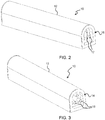
- FIG. 2 shows one luminaire 10 from a first end.
- the luminaire 10 has an elongate housing 12.
- the first end of the housing has a male electrical connector 16.
- the male electrical connector 16 comprises male connector terminals in the form of a set of three pins 17 projecting in a direction parallel to the elongate axis of the housing 12.
- Figure 3 shows the luminaire 10 from the opposite, second, end.
- the second end of the housing has a female electrical connector 14.
- the female electrical connector 14 comprises female connector terminals in the form of a set of three sleeves 15 also projecting in a direction parallel to the elongate axis of the housing 12.
- Figure 4 shows the connector piece 20.
- the connector piece 20 is for coupling one end of one housing to an opposite gender end of an adjacent housing.
- the connector piece 20 comprises a male connector unit 30 suitable for connection to the female electrical connector 14 and a female connector unit 40 suitable for connection to the male electrical connector 16.
- connection between the male connector unit 30 and the female electrical connector 14 is a push fit and the connection between the female connector unit 40 and the male electrical connector 16 is also a push fit.
- the push fit is parallel to the elongate axis of the housing 12.
- FIG. 5 shows the male connector unit 30 in more detail.
- the male connector unit has an end wall 32 from which connector terminals, in particular a set of male connection pins 33, extend. These are designed to engage with the sleeves 15.
- a cover 34 extends from the other (opposite) side of the end wall 32.
- FIG 5 also shows a pair of mechanical clips 35 for coupling to an adjacent luminaire housing.
- Each clip 35 comprises a barb which engages with a slot in the end face of the luminaire housing.
- the slots in the end faces can be seen in Figures 2 and 3 .
- Figure 6 shows a cross section through the male connector unit 30 in a vertical plane.
- the end wall 32 has a shroud 50 around the connection pins 33.
- the shroud fits into a recess in the end face of the luminaire housing. A portion of the shroud forms the mechanical clips 35.
- the cover 34 has a bore 52 with a recessed top 54. This is for receiving a bolt to couple the male and female connector units 30,40.
- the bore (and bolt) lie along the rotation axis 21.
- Each male connection pin 33 is electrically coupled to an associated first connecting element in the form a vertical conductor pin 36 housed within a column 37.
- One column and its conductor pin is shown in cross section, and one column behind is shown solid.
- the vertical conductor pin 36 is biased by a spring 38 against conductor tracks (discussed below).
- a male connection strip 39 is provided for each vertical conductor pin 36. It extends between one of the male connection pins 33 and the vertical conductor pin 36. There is an electrical connection between the male connection pin 33 and the conductor pin 36 made by the male connection strip 39.
- the ends of the male connection strip have contact pawls (one pawl can be seen at each end in Figure 6 , whereas Figure 13 below shows that there is a pair of pawls at each end). These pawls contact the inner surface of the male connection pin 33 at one end of the male connection strip 39 and contact the inner surface of a cage (shown more clearly in Figure 11 ) connected to the vertical conductor pin 36 at the other end.
- connection strips are for example made of spring steel, so that a bias is provided to the pawls to maintain electrical contact.
- connection strips 39 avoids the need for any flexible connections such as wiring.
- the bias provided to the vertical conductor pin 36 is enabled by the spring 38, but the electrical connection to the vertical conductor pin 36 is by the rigid connection strip 39.
- Figure 7 shows a view of the male connector unit 30 from beneath the cover 34 (the male connection strips 39 and vertical conductor pins 36 are removed in this view). It shows a set of three columns 37 for supporting the vertical conductor pins 36.
- FIG 8 shows a first view of the female connector unit 40 in more detail.
- the female connector unit has an end wall 42 from which connector terminals, in particular a set of female connection sleeves 43, extend. These are designed to engage with the pins 17 of the male electrical connector 16.
- a base 44 extends from the other side of the end wall 32.
- Figure 8 also shows mechanical clips 45 for coupling to an adjacent luminaire housing.
- the clips 45 are identical to clips 35, and thus comprises a barb which engages with a slot in the end face of the luminaire housing.
- the clips are again part of a shroud 50.
- Figure 9 shows a second view of the female connector unit 40 in more detail.
- the top of the base 44 carries a printed circuit board 90 which forms a second connecting element in the form a set of arcuate conductor tracks 46 concentric around the rotation axis 11.
- the base has an opening 47 for receiving the bore 52 of the male connector unit 30 so that a rotary coupling is defined between the male and female connector units 30,40 for rotation about the rotation axis 21.
- the female connector unit 40 has a set of female connection strips 48, with one for each track 46.
- Each female connection strip 48 connects between a female connector terminal, i.e. one of the sleeves 15, and a respective track 46. It is soldered to the track.
- the rotary coupling between the male and female connector units 30,40 implements an electrical connection between the male and female connector units.
- the first connecting element (vertical conductor pins 36) and the second connecting element (arcuate tracks 46) are slidably coupled to each other.
- Figure 10 shows the connector piece 20 with the male and female connector units 30,40 coupled together, in cross section.
- Figure 10 shows a nut 60 and bolt 62 used to connect the male and female connector units 30,40.
- the bolt extends along the rotation axis 21.
- the bolt thus defines the rotation axle.
- the connector piece is assembled by mounting the cover 34 over the base 44 and fixing the nut. This means it is possible to make the connection between luminaires when space is tight, because the male and female connector units 30,40 can be attached to the luminaire housings separately, and then coupled together without requiring any linear movement (along the elongate axis of the luminaire housing) of the luminaires.
- the male and female connector units 30,40 can be disassembled.
- the base 40 can be dropped down relative to the cover 34.
- a luminaire can then be removed from a line without needing space to disconnect the push fit connections between the luminaire and the connector pieces at each end.
- one luminaire may be dropped out of a line of luminaires, and a replacement luminaire may be fitted in the same way.
- the connector piece 20 enables two luminaire housings of the same design to be connected together, with a rotary electrical and mechanical coupling implemented by the connector piece 20.
- the rotary coupling makes use of a sliding coupling between connecting elements, i.e., the vertical conductor pins 36 and the arcuate conductor tracks 46. This avoids the need for flexible wire connections, so that the connector piece 20 may be formed with rigid parts.
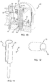
- Figure 11 shows one vertical conductor pin 36 more clearly. It has a top cage 54 for housing the pawls at the associated end of the male connection strip 39.
- the spring 38 abuts the top of the pin 36, in particular the top of the top cage 54.
- the top cage 54 has a slot 55 allowing insertion of the associated end of the male connection strip 39.
- Figure 12 shows one male connection pin 33 (i.e. one of the connector terminals of the male connector unit) more clearly. It also has a slot 56. The pawls at the associated end of the male connection strip 39 engage with the sides of this slot 56.
- Figure 13 shows the male connection strip 39 more clearly. It engages with the slot 55 in the cage of the vertical conductor pin 36 at one end and it engages with the slot 56 in the male connection pin 33 at the other end.
- the male connection strip 39 is horizontal in use.
- the spring 38 biases the vertical conductor pin 36 downwardly, for example pushing down from the top of the cage 54 of the vertical conductor pin 36, and the slot 55 in the cage 54 of the vertical conductor pin 36 can allow the end of the male connection strip 39 to slide within the cage 54 and keep the electrical engagement between the male connection pin 33 and the vertical conductor pin 36.
- the spring 38 provides a preload to the vertical conductor pin 36. After assembly, no relative movement is needed between the spring 38 and the vertical conductor pin 36 (so the sliding in the slot 55 takes place during assembly).
- Figure 14 shows a contact pin cap 80. Its position in the assembly is shown in Figure 6 .
- the contact pin cap is used to fix the vertical conductor pin 36 and spring 38 in a bore of the main body of the male connector unit 30.
- the contact pin cap has a set of four clips in this example, which are an interference fit between into the bore, to provide a fixing force to hold the vertical conductor pin 36 and spring 38.
- FIG. 15 shows the female connector unit 40 with the printed circuit board and female connection strips removed.
- FIG 16 shows female connection strip 48 more clearly. It has a tab 70 at one end for soldering to a track of the printed circuit board and a grip 72 at the other end for gripping the female connection sleeve 43 (i.e. one of the connector terminals of the female connector unit).
- This grip 72 is in the form of a pair of pawls 72a similar to those of the male connection strip.
- the female connection strip is for example of spring steel so that a bias is provided to the pawls 72a to maintain a good electrical contact with the female connection sleeve 43, for example contacting the inner bore of the female connection sleeve 43.
- Figure 17 shows the printed circuit board 90 with its three concentric arcuate tracks 46. It may be mounted to the base using a pair of plastic screws or rivets.
- the printed circuit board has a shape such that there is only one possible rotational position.
- the three electrical tracks are typically live (L), neutral (N) and ground (GND).
- the arcuate path length is preferably sufficient to cover the range of rotation shown in Figure 1 , from -90 degrees to + 90 degrees.
- the electrical connection between the luminaires is a parallel electrical connection, i.e. live to live, neutral to neutral and ground to ground.
- any number of luminaires may be connected (within the power capability of the supply).
- a cushion may be mounted between the male and female connector unit 30,40. This may be used to provide damping when the male and female connector units are rotated relative to each other.
- the male and female connector units are for example injection molded parts.
- the male connection pins 33 and the female connection sleeves 43 are for example fixed directly through the injection process, e.g. by over-molding.
- the male connector unit may have the tracks and the female connector unit may have the pins.
- Different internal connections between the external connections of the connector piece (pins 33 and sleeves 43) and the internal connecting elements (vertical conductor pins 36 and arcuate tracks 46) may be provided.
Landscapes
- Engineering & Computer Science (AREA)
- General Engineering & Computer Science (AREA)
- Arrangement Of Elements, Cooling, Sealing, Or The Like Of Lighting Devices (AREA)
Priority Applications (1)
| Application Number | Priority Date | Filing Date | Title |
|---|---|---|---|
| EP20169008.8A EP3892915A1 (fr) | 2020-04-09 | 2020-04-09 | Pièce de raccord pour un système de luminaire et système de luminaire utilisant la pièce de raccord |
Applications Claiming Priority (1)
| Application Number | Priority Date | Filing Date | Title |
|---|---|---|---|
| EP20169008.8A EP3892915A1 (fr) | 2020-04-09 | 2020-04-09 | Pièce de raccord pour un système de luminaire et système de luminaire utilisant la pièce de raccord |
Publications (1)
| Publication Number | Publication Date |
|---|---|
| EP3892915A1 true EP3892915A1 (fr) | 2021-10-13 |
Family
ID=70285485
Family Applications (1)
| Application Number | Title | Priority Date | Filing Date |
|---|---|---|---|
| EP20169008.8A Pending EP3892915A1 (fr) | 2020-04-09 | 2020-04-09 | Pièce de raccord pour un système de luminaire et système de luminaire utilisant la pièce de raccord |
Country Status (1)
| Country | Link |
|---|---|
| EP (1) | EP3892915A1 (fr) |
Cited By (1)
| Publication number | Priority date | Publication date | Assignee | Title |
|---|---|---|---|---|
| IT202400000435A1 (it) * | 2024-01-11 | 2025-07-11 | Ad Illuminazione Srl | Sistema di illuminazione |
Citations (4)
| Publication number | Priority date | Publication date | Assignee | Title |
|---|---|---|---|---|
| US6607284B1 (en) * | 2002-09-17 | 2003-08-19 | Shenghui Lighting Co., Ltd. | Lighting structure used for decorating |
| KR20110058946A (ko) * | 2009-11-27 | 2011-06-02 | 한국광기술원 | 가변 블록형 조명장치 |
| GB2496189A (en) * | 2011-11-07 | 2013-05-08 | David Morgan | Articulated lights. |
| DE102015214958A1 (de) * | 2015-08-05 | 2017-02-09 | H4X E.U. | Profilleuchtenanordnung, Verbindungselement für eine solche Profilleuchtenanordnung und Verfahren zur Herstellung einer solchen Profilleuchtenanordnung |
-
2020
- 2020-04-09 EP EP20169008.8A patent/EP3892915A1/fr active Pending
Patent Citations (4)
| Publication number | Priority date | Publication date | Assignee | Title |
|---|---|---|---|---|
| US6607284B1 (en) * | 2002-09-17 | 2003-08-19 | Shenghui Lighting Co., Ltd. | Lighting structure used for decorating |
| KR20110058946A (ko) * | 2009-11-27 | 2011-06-02 | 한국광기술원 | 가변 블록형 조명장치 |
| GB2496189A (en) * | 2011-11-07 | 2013-05-08 | David Morgan | Articulated lights. |
| DE102015214958A1 (de) * | 2015-08-05 | 2017-02-09 | H4X E.U. | Profilleuchtenanordnung, Verbindungselement für eine solche Profilleuchtenanordnung und Verfahren zur Herstellung einer solchen Profilleuchtenanordnung |
Cited By (2)
| Publication number | Priority date | Publication date | Assignee | Title |
|---|---|---|---|---|
| IT202400000435A1 (it) * | 2024-01-11 | 2025-07-11 | Ad Illuminazione Srl | Sistema di illuminazione |
| WO2025149996A1 (fr) * | 2024-01-11 | 2025-07-17 | Ad Illuminazione Srl | Système d'éclairage |
Similar Documents
| Publication | Publication Date | Title |
|---|---|---|
| US7661870B2 (en) | Field bendable line voltage track lighting system | |
| EP2048746A1 (fr) | Système de connexion de barre de bus | |
| US6273750B1 (en) | Connector and cable system for panel-mounted circuitry | |
| US5785411A (en) | Track lighting system | |
| US8262264B2 (en) | Interlocking system for hanging decorative lights and fixtures | |
| US9905976B1 (en) | Mounting strap having a connector to connect an electric fixture to a junction box | |
| US9293848B2 (en) | Electrical connector for use with printed circuit boards | |
| US9423112B2 (en) | Light fixture | |
| US20160164235A1 (en) | Contact element for a plug arrangement in a bus system, more particularly an externally routed bus system | |
| US8480420B2 (en) | Outlet and light assembly with internal wiring connection | |
| CN101552390B (zh) | 具有护套支座的插接连接器 | |
| US4533202A (en) | Multiple electrical connector and block with printed circuit board connector clip | |
| US6033239A (en) | Connector for track lighting systems | |
| CN109716597B (zh) | 用于模块化插接连接器的过压保护模块 | |
| US4580864A (en) | Modular connecting blocks | |
| EP3892915A1 (fr) | Pièce de raccord pour un système de luminaire et système de luminaire utilisant la pièce de raccord | |
| CN107431285B (zh) | 带有外部的电气构件的接线盒 | |
| US7247052B2 (en) | Shield connection | |
| CN101779338B (zh) | 具有柔性区域的连接器 | |
| EP2678903B1 (fr) | Unité de connexion électrique modulaire | |
| US12060981B2 (en) | Adapter for electrically connecting a lighting device to an electrical track, lighting system comprising such an adapter and an electrical track | |
| US20170288563A1 (en) | Series module assembly with a power bus system | |
| CN215070541U (zh) | 分线器及取电装置 | |
| CN116565618B (zh) | 模组连接器 | |
| WO2019197271A1 (fr) | Connecteur d'alimentation à cartes multiples |
Legal Events
| Date | Code | Title | Description |
|---|---|---|---|
| PUAI | Public reference made under article 153(3) epc to a published international application that has entered the european phase |
Free format text: ORIGINAL CODE: 0009012 |
|
| STAA | Information on the status of an ep patent application or granted ep patent |
Free format text: STATUS: THE APPLICATION HAS BEEN PUBLISHED |
|
| AK | Designated contracting states |
Kind code of ref document: A1 Designated state(s): AL AT BE BG CH CY CZ DE DK EE ES FI FR GB GR HR HU IE IS IT LI LT LU LV MC MK MT NL NO PL PT RO RS SE SI SK SM TR |