EP3892995A1 - Analysevorrichtung und analyseverfahren - Google Patents
Analysevorrichtung und analyseverfahren Download PDFInfo
- Publication number
- EP3892995A1 EP3892995A1 EP19893721.1A EP19893721A EP3892995A1 EP 3892995 A1 EP3892995 A1 EP 3892995A1 EP 19893721 A EP19893721 A EP 19893721A EP 3892995 A1 EP3892995 A1 EP 3892995A1
- Authority
- EP
- European Patent Office
- Prior art keywords
- gas
- combustion
- sample
- concentration
- electric furnace
- Prior art date
- Legal status (The legal status is an assumption and is not a legal conclusion. Google has not performed a legal analysis and makes no representation as to the accuracy of the status listed.)
- Withdrawn
Links
- 238000004458 analytical method Methods 0.000 title claims description 70
- 238000002485 combustion reaction Methods 0.000 claims abstract description 47
- 239000012895 dilution Substances 0.000 claims abstract description 33
- 238000010790 dilution Methods 0.000 claims abstract description 33
- 230000007246 mechanism Effects 0.000 claims abstract description 24
- 230000008859 change Effects 0.000 claims abstract description 12
- 239000007789 gas Substances 0.000 claims description 233
- MYMOFIZGZYHOMD-UHFFFAOYSA-N Dioxygen Chemical compound O=O MYMOFIZGZYHOMD-UHFFFAOYSA-N 0.000 claims description 6
- 229910001882 dioxygen Inorganic materials 0.000 claims description 6
- 238000013500 data storage Methods 0.000 claims description 5
- 238000010521 absorption reaction Methods 0.000 claims description 3
- 239000002360 explosive Substances 0.000 description 11
- RNFJDJUURJAICM-UHFFFAOYSA-N 2,2,4,4,6,6-hexaphenoxy-1,3,5-triaza-2$l^{5},4$l^{5},6$l^{5}-triphosphacyclohexa-1,3,5-triene Chemical compound N=1P(OC=2C=CC=CC=2)(OC=2C=CC=CC=2)=NP(OC=2C=CC=CC=2)(OC=2C=CC=CC=2)=NP=1(OC=1C=CC=CC=1)OC1=CC=CC=C1 RNFJDJUURJAICM-UHFFFAOYSA-N 0.000 description 9
- 239000003063 flame retardant Substances 0.000 description 9
- 238000000034 method Methods 0.000 description 9
- 230000006870 function Effects 0.000 description 7
- 238000010586 diagram Methods 0.000 description 5
- 239000002184 metal Substances 0.000 description 5
- 229910052799 carbon Inorganic materials 0.000 description 4
- 239000011368 organic material Substances 0.000 description 4
- 229910052717 sulfur Inorganic materials 0.000 description 4
- 238000011144 upstream manufacturing Methods 0.000 description 4
- OKTJSMMVPCPJKN-UHFFFAOYSA-N Carbon Chemical compound [C] OKTJSMMVPCPJKN-UHFFFAOYSA-N 0.000 description 3
- CWYNVVGOOAEACU-UHFFFAOYSA-N Fe2+ Chemical compound [Fe+2] CWYNVVGOOAEACU-UHFFFAOYSA-N 0.000 description 3
- 229910000831 Steel Inorganic materials 0.000 description 3
- NINIDFKCEFEMDL-UHFFFAOYSA-N Sulfur Chemical compound [S] NINIDFKCEFEMDL-UHFFFAOYSA-N 0.000 description 3
- 239000000919 ceramic Substances 0.000 description 3
- 238000010438 heat treatment Methods 0.000 description 3
- 229910010272 inorganic material Inorganic materials 0.000 description 3
- 239000011147 inorganic material Substances 0.000 description 3
- 238000010926 purge Methods 0.000 description 3
- 239000010959 steel Substances 0.000 description 3
- 239000011593 sulfur Substances 0.000 description 3
- XKRFYHLGVUSROY-UHFFFAOYSA-N Argon Chemical compound [Ar] XKRFYHLGVUSROY-UHFFFAOYSA-N 0.000 description 2
- IJGRMHOSHXDMSA-UHFFFAOYSA-N Atomic nitrogen Chemical compound N#N IJGRMHOSHXDMSA-UHFFFAOYSA-N 0.000 description 2
- 238000005033 Fourier transform infrared spectroscopy Methods 0.000 description 2
- 101100023111 Schizosaccharomyces pombe (strain 972 / ATCC 24843) mfc1 gene Proteins 0.000 description 2
- 230000001276 controlling effect Effects 0.000 description 2
- 238000007865 diluting Methods 0.000 description 2
- 229910001873 dinitrogen Inorganic materials 0.000 description 2
- 230000000694 effects Effects 0.000 description 2
- 238000001745 non-dispersive infrared spectroscopy Methods 0.000 description 2
- 238000005303 weighing Methods 0.000 description 2
- 229910052786 argon Inorganic materials 0.000 description 1
- 238000004364 calculation method Methods 0.000 description 1
- 238000004140 cleaning Methods 0.000 description 1
- 239000003245 coal Substances 0.000 description 1
- 230000008094 contradictory effect Effects 0.000 description 1
- 230000003247 decreasing effect Effects 0.000 description 1
- 238000001514 detection method Methods 0.000 description 1
- 230000020169 heat generation Effects 0.000 description 1
- 238000012423 maintenance Methods 0.000 description 1
- 238000012986 modification Methods 0.000 description 1
- 230000004048 modification Effects 0.000 description 1
- 230000003647 oxidation Effects 0.000 description 1
- 238000007254 oxidation reaction Methods 0.000 description 1
- 238000004445 quantitative analysis Methods 0.000 description 1
- 230000009467 reduction Effects 0.000 description 1
- 230000001105 regulatory effect Effects 0.000 description 1
- 239000007787 solid Substances 0.000 description 1
- 239000000243 solution Substances 0.000 description 1
- 238000000870 ultraviolet spectroscopy Methods 0.000 description 1
Images


Classifications
-
- G—PHYSICS
- G01—MEASURING; TESTING
- G01N—INVESTIGATING OR ANALYSING MATERIALS BY DETERMINING THEIR CHEMICAL OR PHYSICAL PROPERTIES
- G01N31/00—Investigating or analysing non-biological materials by the use of the chemical methods specified in the subgroup; Apparatus specially adapted for such methods
- G01N31/12—Investigating or analysing non-biological materials by the use of the chemical methods specified in the subgroup; Apparatus specially adapted for such methods using combustion
-
- G—PHYSICS
- G01—MEASURING; TESTING
- G01N—INVESTIGATING OR ANALYSING MATERIALS BY DETERMINING THEIR CHEMICAL OR PHYSICAL PROPERTIES
- G01N33/00—Investigating or analysing materials by specific methods not covered by groups G01N1/00 - G01N31/00
- G01N33/0004—Gaseous mixtures, e.g. polluted air
- G01N33/0009—General constructional details of gas analysers, e.g. portable test equipment
- G01N33/0011—Sample conditioning
- G01N33/0018—Sample conditioning by diluting a gas
-
- G—PHYSICS
- G01—MEASURING; TESTING
- G01N—INVESTIGATING OR ANALYSING MATERIALS BY DETERMINING THEIR CHEMICAL OR PHYSICAL PROPERTIES
- G01N33/00—Investigating or analysing materials by specific methods not covered by groups G01N1/00 - G01N31/00
- G01N33/0004—Gaseous mixtures, e.g. polluted air
- G01N33/0009—General constructional details of gas analysers, e.g. portable test equipment
- G01N33/0027—General constructional details of gas analysers, e.g. portable test equipment concerning the detector
- G01N33/0031—General constructional details of gas analysers, e.g. portable test equipment concerning the detector comprising two or more sensors, e.g. a sensor array
-
- G—PHYSICS
- G01—MEASURING; TESTING
- G01N—INVESTIGATING OR ANALYSING MATERIALS BY DETERMINING THEIR CHEMICAL OR PHYSICAL PROPERTIES
- G01N33/00—Investigating or analysing materials by specific methods not covered by groups G01N1/00 - G01N31/00
- G01N33/0004—Gaseous mixtures, e.g. polluted air
- G01N33/0009—General constructional details of gas analysers, e.g. portable test equipment
- G01N33/0027—General constructional details of gas analysers, e.g. portable test equipment concerning the detector
- G01N33/0036—General constructional details of gas analysers, e.g. portable test equipment concerning the detector specially adapted to detect a particular component
- G01N33/004—CO or CO2
-
- G—PHYSICS
- G01—MEASURING; TESTING
- G01N—INVESTIGATING OR ANALYSING MATERIALS BY DETERMINING THEIR CHEMICAL OR PHYSICAL PROPERTIES
- G01N33/00—Investigating or analysing materials by specific methods not covered by groups G01N1/00 - G01N31/00
- G01N33/0004—Gaseous mixtures, e.g. polluted air
- G01N33/0009—General constructional details of gas analysers, e.g. portable test equipment
- G01N33/0027—General constructional details of gas analysers, e.g. portable test equipment concerning the detector
- G01N33/0036—General constructional details of gas analysers, e.g. portable test equipment concerning the detector specially adapted to detect a particular component
- G01N33/0042—SO2 or SO3
-
- G—PHYSICS
- G01—MEASURING; TESTING
- G01N—INVESTIGATING OR ANALYSING MATERIALS BY DETERMINING THEIR CHEMICAL OR PHYSICAL PROPERTIES
- G01N33/00—Investigating or analysing materials by specific methods not covered by groups G01N1/00 - G01N31/00
- G01N33/20—Metals
- G01N33/202—Constituents thereof
- G01N33/2022—Non-metallic constituents
Definitions
- the present invention relates to an analysis device and an analysis method for analyzing elements, such as carbon (C) and sulfur (S) included in a sample.
- Patent Literature 1 discloses an analysis device in which a container (boat) accommodating a sample is introduced into an electric furnace, and a gas generated from the sample heated and burned in the electric furnace is analyzed.
- a type of analysis device that analyzes a sample that is difficult to burn such as steel or non-ferrous metal (hereinafter, also referred to as a flame-retardant sample) is configured to supply, for example, a high-concentration oxygen gas having a concentration close to 100% to inside of an electric furnace as a combustion-supporting gas, and to promote combustion of the sample.
- an easily combustible sample hereinafter, also referred to as an explosive sample
- the amount of gas generated by rapid combustion of the sample is large, a peak of a signal detected by a gas analyzer becomes steep, and there arises a problem that accurate analysis cannot be performed unless a detector has a high resolution.
- the explosive sample is scattered due to rapid combustion, this also causes a decrease in analysis accuracy and further requires maintenance such as cleaning of the inside of the electric furnace.
- the component that burns in the low temperature range and the component that burns in the high temperature range included in the mixed sample can be separated and analyzed by, for example, providing the electric furnace with a function of increasing the temperature and increasing the temperature in the electric furnace.
- Patent Literature 1 JP 2952703 B2
- the present invention has been made to solve the above problems at once, and a main object of the present invention is to flexibly change an amount of combustion in accordance with a type of sample, promote combustion, suppress rapid combustion, and achieve analysis of various samples.
- an analysis device of the present invention includes an electric furnace into which a container accommodating a sample is introduced, a gas analyzer configured to analyze a gas generated from the sample that is heated and burned in the electric furnace, a mixed gas supply path configured to supply, to the electric furnace, a mixed gas obtained by mixing a dilution gas with a combustion-supporting gas that promotes combustion of the sample, and a concentration changing mechanism configured to change a concentration of the combustion-supporting gas in the mixed gas.
- the analysis device configured in this way allows the concentration of the combustion-supporting gas in the mixed gas to be changed by the concentration changing mechanism.
- combustion of the sample can be promoted by increasing a combustion-supporting gas concentration, and rapid combustion of the sample can be suppressed by lowering the combustion-supporting gas concentration.
- a type of a sample such as a flame-retardant sample that is difficult to burn, an explosive sample that is easy to burn, and a mixed sample including a component that burns in a low temperature range and a component that burns in a high temperature range, it is possible to promote combustion, suppress rapid combustion, and thus analyze various samples.
- the combustion-supporting gas is preferably a high-concentration oxygen gas.
- the electric furnace is preferably pressurized inside when the sample is heated.
- the combustion of a flame-retardant sample can be promoted by pressurizing the inside of the electric furnace and increasing the combustion-supporting gas concentration, and the rapid combustion of an explosive sample can be suppressed by decreasing the combustion-supporting gas concentration while pressurizing the inside of the electric furnace. Then, it is possible to analyze both the flame-retardant sample and the explosive sample with the same analysis device.
- the analysis device preferably further includes a furnace controller configured to control an operation of the electric furnace, in which the furnace controller is configured to heat the electric furnace before the container accommodating the sample is introduced into the electric furnace.
- time from the introduction of the container to the combustion of the sample can be made shorter than in a configuration in which the electric furnace is heated after the container accommodating the sample is introduced into the electric furnace.
- the analysis takes less time, and the analysis can be more efficient.
- the container is preferably introduced into the electric furnace through an opening formed in a side wall, and a driving gas for an opening and closing lid that opens and closes the opening is preferably also used as the dilution gas.
- This configuration eliminates the need for preparing a dedicated dilution gas for diluting the combustion-supporting gas.
- the combustion-supporting gas and the dilution gas have different viscosity, and thus a viscosity of the mixed gas changes depending on the combustion-supporting gas concentration in the mixed gas. This change in viscosity can affect analysis accuracy.
- the analysis device preferably further includes a calculator configured to calculate a mass concentration of a component included in the sample on the basis of a light intensity signal outputted from the gas analyzer, and a correction data storage configured to store correction data that associates a target combustion-supporting gas concentration, which is set in advance as a concentration of the combustion-supporting gas in the mixed gas, with a correction coefficient, in which the calculator corrects the mass concentration that has been calculated, using the target combustion-supporting gas concentration and the correction coefficient obtained from the correction data.
- a calculator configured to calculate a mass concentration of a component included in the sample on the basis of a light intensity signal outputted from the gas analyzer
- a correction data storage configured to store correction data that associates a target combustion-supporting gas concentration, which is set in advance as a concentration of the combustion-supporting gas in the mixed gas, with a correction coefficient, in which the calculator corrects the mass concentration that has been calculated, using the target combustion-supporting gas concentration and the correction coefficient obtained from the correction data.
- the analysis device preferably further includes a concentration controller configured to control the concentration changing mechanism on the basis of a light intensity signal outputted from the gas analyzer or a concentration of a component included in the sample calculated on the basis of the light intensity signal.
- the gas analyzer preferably has a non-dispersive infrared detector, and the combustion-supporting gas and the dilution gas preferably have an identical infrared absorption rate.
- an analysis method of the present invention is an analysis method using an analysis device including an electric furnace into which a container accommodating a sample is introduced, a gas analyzer configured to analyze a gas generated from the sample that is heated and burned in the electric furnace, and a mixed gas supply path configured to supply, to the electric furnace, a mixed gas obtained by mixing a dilution gas with a combustion-supporting gas that promotes combustion of the sample, the analysis method including changing a concentration of the combustion-supporting gas in the mixed gas, and supplying the mixed gas from the mixed gas supply path to the electric furnace.
- This analysis method can also have the same effect as the above analysis device.
- the present invention described above makes it possible to flexibly change the amount of combustion in accordance with the type of sample such as a flame-retardant sample, an explosive sample, a mixed sample, and the like, promote combustion, suppress rapid combustion, and analyze various samples.
- An analysis device 100 heats and burns a powdery or bulk solid sample, and analyzes elements such as carbon (C) and sulfur (S) included in the sample from a gas generated by the heating and burning.
- elements such as carbon (C) and sulfur (S) included in the sample from a gas generated by the heating and burning.
- the sample include those containing an inorganic material such as steel and non-ferrous metal, those containing an organic material such as coal, and those containing both an inorganic material and an organic material.
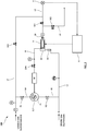
- this analysis device 100 includes an electric furnace 3 in which a container 2 accommodating a sample W is disposed and a gas analyzer 4 that analyzes a gas generated from the sample W heated and burned in the electric furnace 3.
- the container 2 accommodates the sample W, for example, in powdery form inside.
- the container 2 according to the present embodiment has a long shape having an opening at a top, and is specifically a magnetic combustion boat.
- the shape of the container 2 is not limited to this, and various shapes can be used.
- the container 2 not accommodating the sample W is air-baked, or the container 2 accommodating the sample W is heated to heat the sample W to generate gas.
- the electric furnace 3 has a space 3S extending in a horizontal direction from an opening 3H formed in a side wall, and the container 2 is disposed in the space 3S via the opening 3H.
- the electric furnace 3 includes a furnace body 31 where the container 2 is put in and out, an electric resistor (not shown) that is provided around the furnace body 31 and heats the furnace body 31, and a power supply circuit (not shown) that supplies electric power to the electric resistor and energizes the electric resistor to generate heat.
- the furnace body 31 is, for example, a cylindrical ceramic molded body, and has the space 3S that can accommodate the container 2 inside.
- the opening 3H is formed at one end of the furnace body 31.
- a gas outlet 3P for leading the gas generated from the sample W to the gas analyzer 4 is formed.
- a method for heating the furnace body 31 may be a method in which an electric current is passed through an electric resistance furnace to perform resistance heating (Joule heat generation).
- the furnace body 31 includes a conductive metal.
- An opening and closing lid 32 is provided at the opening 3H of the furnace body 31.
- the opening and closing lid 32 moves between a closing position that closes the opening 3H and an opening position that opens the opening 3H, and is driven by an actuator 33 such as an air cylinder, for example.
- the analysis device 100 includes a driving gas flow path L1 through which a driving gas for driving the opening and closing lid 32 flows.
- the driving gas is introduced from a first end opening, and a second end opening is connected to the actuator 33.
- the driving gas for example, nitrogen gas or air is used.
- the gas analyzer 4 analyzes the gas generated in the electric furnace 3 and obtains a content value of a target component included in the sample W, and analyzes the gas using, for example, a non-dispersive infrared absorption method (NDIR method). Specifically, the gas analyzer 4 has a non-dispersive infrared detector (not shown) and determines the content value of carbon (C), sulfur (S), and the like included in the sample W by detecting CO 2 , CO, SO 2 , and the like included in the gas derived from the electric furnace 3.
- the analysis device 100 may include a plurality of the gas analyzers 4.
- the gas analyzer 4 is provided on an analysis flow path L2 whose first end opening communicates with the gas outlet 3P of the electric furnace 3 described above, and a first on-off valve SV1 and a filter F are provided upstream of the gas analyzer 4 on the analysis flow path L2.
- the analysis device 100 is provided with an air release flow path L3 branched from upstream of the first on-off valve SV1 on the analysis flow path L2.
- the air release flow path L3 is provided with a second on-off valve SV2.
- the analysis device 100 includes a combustion-supporting gas flow path L4 through which a combustion-supporting gas that promotes combustion of the sample flows, a dilution gas flow path L5 through which a dilution gas that dilutes the combustion-supporting gas flows, a gas mixer 5 that mixes the dilution gas with the combustion supporting gas and generates a mixed gas, a mixed gas supply path L6 that supplies the mixed gas to the electric furnace 3, and a control device 6 that controls various operations of the analysis device 100.
- the combustion-supporting gas is introduced from a first end opening, and a second end opening is connected to the gas mixer 5.
- the combustion-supporting gas is, for example, oxygen gas having a concentration of 100% or a high concentration close to 100% (for example, a concentration of 90% or more).
- the combustion-supporting gas flow path L4 is provided with a regulator R1, which regulates the combustion-supporting gas to a predetermined pressure (for example, 150 kPa).
- a purging flow path L7 is provided, which is branched from upstream of the regulator R1 in the combustion-supporting gas flow path L4 and connected between the first on-off valve SV1 in the analysis flow path L2 described above and the gas analyzer 4.
- the combustion support gas is also used as a purge gas.
- This purging flow path L7 is provided with a third on-off valve SV3.
- the dilution gas is introduced from a first end opening, and a second end opening is connected to the gas mixer 5.
- the dilution gas is a gas that is inert to the combustion-supporting gas or the gas generated by the combustion of the sample, and is, for example, nitrogen gas or argon gas.
- the driving gas that drives the opening and closing lid 32 described above is also used as the dilution gas. That is, the dilution gas flow path L5 and the driving gas flow path L1 are common in the upstream.
- the dilution gas flow path L5 branches at a branch point in a middle and is connected to the gas mixer 5, and the driving gas flow path L1 branches at the same branch point and is connected to the actuator 33.
- a regulator R2 is provided downstream of the branch point in the dilution gas flow path L5, and the mixed gas led out from the gas mixer 5 is regulated to a predetermined pressure (for example, 70 kPa).
- the gas mixer 5 is connected to the combustion-supporting gas flow path L4 and the dilution gas flow path L5.
- the gas mixer 5 has a first introduction port (not shown) to which the second end opening of the combustion-supporting gas flow path L4 is connected and into which the combustion-supporting gas is introduced, a second introduction port (not shown) to which the second end opening of the dilution gas flow path L5 is connected and into which the dilution gas is introduced, and a lead-out port (not shown) to which a first end opening of the mixed gas supply path L6 is connected and through which the mixed gas is led out.
- the gas mixer 5 has a function as a concentration changing mechanism 7 that changes the concentration of the combustion-supporting gas in the mixed gas.
- the concentration changing mechanism 7 is configured to change the concentration of the combustion-supporting gas included in the mixed gas. Specifically, the concentration changing mechanism 7 changes a mixing ratio of the combustion-supporting gas and the dilution gas using, for example, a principle of a capillary flow rate ratio mixing method.
- an operator can change the concentration of the combustion-supporting gas included in the mixed gas in a stepwise manner by operating a concentration switch 71 such as a knob provided in the concentration changing mechanism 7.
- the mixed gas supply path L6 has the first end opening connected to the lead-out port (not shown) of the gas mixer 5 and a second end opening communicating with the inside of the electric furnace 3 and supplying the mixed gas led out from the gas mixer 5 into the electric furnace 3.
- the mixed gas supply path L6 is provided with a buffer BF capable of storing a predetermined capacity of the mixed gas. Further, a fourth on-off valve SV4, a pressure sensor PS, and the like are provided downstream of the buffer BF in the mixed gas supply path L6.
- the buffer BF does not have to be provided.
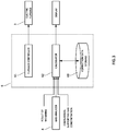
- the control device 6 has a CPU, a memory, a display D, an input device, and the like, and as shown in FIG. 3 , functions as a furnace controller 61, a calculator 62, a correction data storage 63, and the like on the basis of an analysis program stored in the memory.
- the furnace controller 61 controls the power supply circuit (not shown) of the electric furnace 3 to supply electric power to the electric resistor (not shown) and heat the furnace body 31.
- the container 2 not accommodating the sample W is placed in the electric furnace 3, and the container 2 is air-baked to remove deposits and the like of the container 2.
- another electric furnace arranged in parallel with the electric furnace 3 or another electric furnace outside the device may be used.
- the first on-off valve SV1, the third on-off valve SV3, and the fourth on-off valve SV4 are closed, and the second on-off valve SV2 is open.
- the sample W after being weighed is accommodated in the container 2 taken out from the electric furnace 3.
- a result of the weighing of the sample W is input to the control device 6 by the operator, for example.
- the furnace controller 61 heats the electric furnace 3 to a predetermined set temperature before the container 2 accommodating the sample W is placed inside the electric furnace 3.
- the set temperature here can be selected from room temperature to 1,500°C.
- a concentration of the combustion-supporting gas included in the mixed gas (hereinafter, a target combustion-supporting gas concentration) is set in consideration of, for example, the components included in the sample W.
- the operator can set and change the target combustion-supporting gas concentration by the concentration changing mechanism 7.
- the concentration changing mechanism 7 when analyzing a flame-retardant sample that is difficult to burn, the operator operates the concentration changing mechanism 7 so as to set the target combustion-supporting gas concentration to a high level (for example, a concentration of 100%).
- the operator when analyzing an explosive sample that burns easily or a mixed sample that includes a component that burns in a low temperature range and a component that burns in a high temperature range, the operator operates the concentration changing mechanism 7 so as to set the target combustion-supporting gas concentration low.
- the mixed gas is supplied into the electric furnace 3, and thus the inside of the electric furnace 3 is in a pressurized state.
- the inside of the electric furnace 3 does not have to be in a pressurized state.
- the inside of the electric furnace 3 does not have to be pressurized and may be, for example, depressurized.
- the third on-off valve SV3 is opened, the gas analyzer 4 is purged, and then the third on-off valve SV3 is closed. Then, the opening and closing lid 32 is opened, the container 2 accommodating the sample W is placed in the electric furnace 3, and the opening and closing lid 32 is closed. Next, the second on-off valve SV2 is closed, and the first on-off valve SV1 and the fourth on-off valve SV4 are opened.
- the sample W is burned in the electric furnace 3 to generate a gas, and the gas is guided to the gas analyzer 4. Then, the gas analyzer 4 outputs a light intensity signal corresponding to a content value of a target component such as C or S included in the gas to the calculator 62, and the calculator 62 calculates a mass concentration of the target component using this light detection signal and the result of the weighing of the sample W.
- a target component such as C or S included in the gas
- the target combustion-supporting gas concentration is set low until a predetermined time elapses after the container 2 accommodating the sample W is placed in the electric furnace 3, and the setting is changed such that the target combustion-supporting gas concentration becomes high after a lapse of the predetermined time, for example.
- the mass concentration of the component that burns in the low temperature range is calculated before the elapse of the predetermined time, and the mass concentration of the component that burns in the high temperature range is calculated after the elapse of the predetermined time.
- the correction data storage 63 set in a predetermined area of the memory stores correction data that associates the target combustion-supporting gas concentration with a correction coefficient. Then, for example, the target combustion-supporting gas concentration set by the operator is inputted into the control device 6, and then the calculator 62 acquires the correction coefficient using the input target combustion-supporting gas concentration and the correction data, corrects the calculated mass concentration using the correction coefficient, and outputs the corrected mass concentration to a display or the like.
- correction data examples include a calculation formula for calculating a correction coefficient using the target combustion-supporting gas concentration, a viscosity of the combustion-supporting gas, a viscosity of the dilution gas, and the like as parameters, and a table in which the target combustion-supporting gas concentration and the correction coefficient are linked to each other.
- the analysis device 100 configured in this way allows the concentration of the combustion-supporting gas in the mixed gas to be changed by the concentration changing mechanism 7.
- a flame-retardant sample such as metal or ceramic
- combustion can be promoted by increasing the target combustion-supporting gas concentration.
- an explosive sample such as an organic material
- rapid combustion can be suppressed by lowering the target combustion-supporting gas concentration. Therefore, both a flame-retardant sample and an explosive sample can be analyzed using one same analysis device 100.
- an amount of gas generated by combustion of the sample can be reduced by setting the target combustion-supporting gas concentration low to suppress rapid combustion.
- a peak of the signal detected by the gas analyzer becomes gentle, and thus more accurate analysis is possible than when the peak of the detected signal is steep if the same resolution of the detector is the same.
- suppressing rapid combustion of an explosive sample can prevent the sample from scattering, which also leads to accurate quantitative analysis and a reduction in dirt in the electric furnace 3.
- the target combustion-supporting gas concentration is set low at a start of the combustion, and the target combustion-supporting gas concentration is changed to be high in a middle. Then, the component that burns in the low temperature range and the component that burns in the high temperature range can be separated and analyzed. Therefore, for example, a mixed sample including an inorganic material and an organic material can be separated and analyzed with high accuracy.
- a high-concentration oxygen gas with a concentration of 100% is used as the combustion-supporting gas, and the inside of the electric furnace 3 is pressurized when the target combustion-supporting gas concentration is set high.
- the combustion of the sample W can be further promoted in the analysis of the sample W or the like that burns in the high temperature range.
- the driving gas also as the dilution gas eliminates the need for preparing a dedicated dilution gas for diluting the combustion-supporting gas and makes it possible to use the flow path branched from the existing driving gas flow path L1 as the dilution gas flow path L5.
- the flow paths can be therefore configured simply.
- the calculator 62 corrects the calculated mass concentration of the target component using the correction coefficient, a difference in viscosity between the combustion-supporting gas and the dilution gas affects less on the analysis accuracy.
- the present invention is not limited to the above embodiments.
- the target combustion-supporting gas concentration may be automatically controlled by using, for example, the control device 6 or another computer.
- the concentration changing mechanism 7 may be configured to receive a control signal and change the target combustion-supporting gas concentration in a stepwise manner or a stepless manner.
- the concentration changing mechanism 7 may be configured using one or a plurality of flow rate controllers MFC provided separately from the gas mixer 5 as shown in FIG. 4 .
- a specific example of the concentration changing mechanism 7 is a configuration having a first flow rate controller MFC1 as a mass flow controller provided in the combustion-supporting gas flow path L4 and a second flow rate controller MFC2 as a mass flow controller provided in the dilution gas flow path L5 as shown in FIG. 4 .
- control device 6 can control the target combustion-supporting gas concentration by controlling the first flow rate controller MFC1 and the second flow rate controller MFC2, and the target combustion-supporting gas concentration can be controlled automatically.
- an aspect of the control device 6 further has a function as the concentration controller 64 controlling the concentration changing mechanism 7, as shown in FIG. 5 .
- the concentration controller 64 here is configured to control the concentration changing mechanism 7 on the basis of the concentration of the component included in the sample calculated by the calculator 62. Specifically, the concentration controller 64 controls the concentration changing mechanism 7 to decrease the target combustion-supporting gas concentration when the concentration calculated by the calculator 62 exceeds a preset upper limit value.
- This configuration can suppress the combustion of the sample W when an amount of combustion of the sample W is large and the concentration calculated by the calculator 62 exceeds the upper limit value.
- the concentration controller 64 preferably controls a gas mixing mechanism to increase the target combustion-supporting gas concentration when the concentration calculated by the calculator 62 falls below a preset lower limit value.
- This configuration can promote the combustion of the sample W when the amount of combustion of the sample W is small and the concentration calculated by the calculator 62 falls below the lower limit value.
- the concentration controller 64 may be configured to control the concentration changing mechanism 7 on the basis of the light intensity signal outputted from the gas analyzer 4, or may be configured to perform feedback control of the target combustion-supporting gas concentration using the light intensity signal or the concentration calculated by the calculator 62.
- the method in which the target combustion-supporting gas concentration is set low at the beginning and changed to be high in the middle was described above.
- the set temperature of the electric furnace may be changed in the middle.
- the gas analyzer is not limited to the analyzer using the NDIR method described in the above embodiment, but may be an analyzer using a Fourier transform infrared spectroscopy (FTIR) method or an analyzer using a non-dispersive ultraviolet spectroscopy (NDUV) method.
- FTIR Fourier transform infrared spectroscopy
- NDUV non-dispersive ultraviolet spectroscopy
- the present invention can promote the combustion of the sample in the high temperature range and also reduces the amount of combustion of the sample in the low temperature range.
Landscapes
- Health & Medical Sciences (AREA)
- Chemical & Material Sciences (AREA)
- Life Sciences & Earth Sciences (AREA)
- Physics & Mathematics (AREA)
- Combustion & Propulsion (AREA)
- Molecular Biology (AREA)
- Engineering & Computer Science (AREA)
- Analytical Chemistry (AREA)
- Biochemistry (AREA)
- General Health & Medical Sciences (AREA)
- General Physics & Mathematics (AREA)
- Immunology (AREA)
- Pathology (AREA)
- Investigating Or Analyzing Non-Biological Materials By The Use Of Chemical Means (AREA)
- Investigating Or Analysing Materials By Optical Means (AREA)
Applications Claiming Priority (2)
| Application Number | Priority Date | Filing Date | Title |
|---|---|---|---|
| JP2018227541 | 2018-12-04 | ||
| PCT/JP2019/030902 WO2020115946A1 (ja) | 2018-12-04 | 2019-08-06 | 分析装置及び分析方法 |
Publications (2)
| Publication Number | Publication Date |
|---|---|
| EP3892995A1 true EP3892995A1 (de) | 2021-10-13 |
| EP3892995A4 EP3892995A4 (de) | 2022-09-07 |
Family
ID=70975321
Family Applications (1)
| Application Number | Title | Priority Date | Filing Date |
|---|---|---|---|
| EP19893721.1A Withdrawn EP3892995A4 (de) | 2018-12-04 | 2019-08-06 | Analysevorrichtung und analyseverfahren |
Country Status (4)
| Country | Link |
|---|---|
| EP (1) | EP3892995A4 (de) |
| JP (1) | JP7217755B2 (de) |
| CN (1) | CN113167778A (de) |
| WO (1) | WO2020115946A1 (de) |
Families Citing this family (2)
| Publication number | Priority date | Publication date | Assignee | Title |
|---|---|---|---|---|
| CN115917311A (zh) * | 2021-03-12 | 2023-04-04 | 株式会社堀场制作所 | 元素分析装置、元素分析装置的操作方法和元素分析装置的动作程序 |
| WO2023112679A1 (ja) * | 2021-12-14 | 2023-06-22 | 株式会社堀場テクノサービス | 元素分析方法及び元素分析装置 |
Family Cites Families (19)
| Publication number | Priority date | Publication date | Assignee | Title |
|---|---|---|---|---|
| US3698869A (en) * | 1965-08-20 | 1972-10-17 | Perkin Elmer Corp | Analysis of gaseous mixtures |
| US4409336A (en) * | 1981-02-17 | 1983-10-11 | Standard Oil Company (Indiana) | Method of analysis for determining very low sulfur levels in volatilizable samples |
| JPS5983054A (ja) * | 1982-11-04 | 1984-05-14 | Horiba Ltd | 金属中の元素分析装置 |
| FR2607255B1 (fr) * | 1986-11-25 | 1989-09-29 | Inst Francais Du Petrole | Procede et dispositif de determination de la quantite d'au moins un element choisi parmi le carbone, l'hydrogene, le soufre et l'azote d'au moins deux fractions d'un echantillon de matiere organique |
| JP2952703B2 (ja) | 1990-10-13 | 1999-09-27 | 株式会社堀場製作所 | 試料分析装置 |
| JPH06265475A (ja) * | 1993-03-13 | 1994-09-22 | Horiba Ltd | 酸素気流中燃焼ガス分析装置 |
| JP3999313B2 (ja) * | 1997-07-30 | 2007-10-31 | 株式会社堀場製作所 | 金属分析装置の監視方法 |
| JP2000065699A (ja) * | 1998-08-19 | 2000-03-03 | Mitsubishi Chemicals Corp | 分析用試料燃焼装置及び分析用試料燃焼装置における不活性ガス,酸素含有ガス供給制御方法並びに試料燃焼装置を有する分析システム |
| JP3840019B2 (ja) * | 1998-12-25 | 2006-11-01 | 株式会社堀場製作所 | 炭素分別分析装置 |
| JP2003065958A (ja) * | 2001-08-30 | 2003-03-05 | Dia Instr:Kk | 硫黄の分析方法および分析装置 |
| JP3764701B2 (ja) * | 2002-04-10 | 2006-04-12 | 株式会社堀場製作所 | 油分測定方法および装置 |
| JP3998190B2 (ja) * | 2002-12-02 | 2007-10-24 | 株式会社堀場製作所 | 燃焼手段からの排ガス中に含まれている粒子状物質中の窒素化合物の分析方法および分析装置 |
| JP4833052B2 (ja) * | 2006-12-25 | 2011-12-07 | 株式会社堀場製作所 | 酸素雰囲気で融解処理された試料中の元素分析方法および元素分析装置 |
| JP3142280U (ja) * | 2008-03-28 | 2008-06-05 | 株式会社島津製作所 | 有機体炭素測定装置 |
| JP2010008245A (ja) * | 2008-06-27 | 2010-01-14 | Horiba Ltd | 元素分析装置 |
| JP2012202887A (ja) * | 2011-03-28 | 2012-10-22 | Shimadzu Corp | 分析装置 |
| JP6115483B2 (ja) * | 2014-01-22 | 2017-04-19 | 株式会社島津製作所 | 炭素測定装置 |
| JP2016200590A (ja) * | 2015-04-06 | 2016-12-01 | 株式会社三菱化学アナリテック | 窒素の分析方法 |
| JP7101472B2 (ja) * | 2017-07-12 | 2022-07-15 | 株式会社堀場製作所 | 分析装置 |
-
2019
- 2019-08-06 JP JP2020559705A patent/JP7217755B2/ja active Active
- 2019-08-06 EP EP19893721.1A patent/EP3892995A4/de not_active Withdrawn
- 2019-08-06 WO PCT/JP2019/030902 patent/WO2020115946A1/ja not_active Ceased
- 2019-08-06 CN CN201980078198.6A patent/CN113167778A/zh active Pending
Also Published As
| Publication number | Publication date |
|---|---|
| JP7217755B2 (ja) | 2023-02-03 |
| JPWO2020115946A1 (ja) | 2021-10-28 |
| WO2020115946A1 (ja) | 2020-06-11 |
| EP3892995A4 (de) | 2022-09-07 |
| CN113167778A (zh) | 2021-07-23 |
Similar Documents
| Publication | Publication Date | Title |
|---|---|---|
| CN109254108B (zh) | 分析装置和分析方法 | |
| EP3892995A1 (de) | Analysevorrichtung und analyseverfahren | |
| EP2275811B1 (de) | Vorrichtung zur Bestimmung der Zusammensetzung einer insbesondere proteinhaltigen Probe | |
| EP1106985B1 (de) | Verfahren und Vorrichtung zur Analyse von Teilchenmaterial in Gas. | |
| JPWO2011077938A1 (ja) | ガス分析装置 | |
| CN108226268B (zh) | 气体分析装置、气体取样装置和气体分析方法 | |
| JP2015206774A (ja) | 流量調整装置及びこれを備えたガスクロマトグラフ | |
| JP6115483B2 (ja) | 炭素測定装置 | |
| EP2950094A1 (de) | Probenerwärmungsvorrichtung und elementaranalysator | |
| JP7101472B2 (ja) | 分析装置 | |
| EP3336539B1 (de) | Gasanalysevorrichtung, gasprobenentnahmevorrichtung und gasanalyseverfahren | |
| US20190076922A1 (en) | Apparatus and method for controlling a sintering process | |
| KR101462144B1 (ko) | 가열로 연소 제어 시스템 및 방법 | |
| JP6744205B2 (ja) | 元素分析装置及び元素分析方法 | |
| JP5035610B2 (ja) | オイルミスト濃度測定方法およびオイルミスト濃度測定装置 | |
| RU2352933C1 (ru) | Анализатор углерода и серы | |
| JP2020106278A (ja) | 燃焼式炭素分析装置及び炭素分析方法 | |
| CN103926342B (zh) | 基于可控等值比法模拟卷烟燃吸的分析方法及分析装置 | |
| US12196418B2 (en) | Combustion of the CO in secondary metallurgical exhaust gas, with calorific value control and volume flow control | |
| WO2023112679A1 (ja) | 元素分析方法及び元素分析装置 | |
| US20110287372A1 (en) | Method and Device for Monitoring the Combustion Process in a Power Station on the Basis of an Actual Concentration Distribution of a Material | |
| US20050069455A1 (en) | Chemical analyzer for sulfur | |
| CN104698105A (zh) | 基于可控等值比法模拟卷烟燃吸的分析装置 | |
| JP2023148343A (ja) | 元素分析方法、元素分析装置、及び、元素分析装置用プログラム | |
| JP2025174478A (ja) | 元素分析装置、元素分析装置用プログラム及び元素分析方法 |
Legal Events
| Date | Code | Title | Description |
|---|---|---|---|
| STAA | Information on the status of an ep patent application or granted ep patent |
Free format text: STATUS: THE INTERNATIONAL PUBLICATION HAS BEEN MADE |
|
| PUAI | Public reference made under article 153(3) epc to a published international application that has entered the european phase |
Free format text: ORIGINAL CODE: 0009012 |
|
| STAA | Information on the status of an ep patent application or granted ep patent |
Free format text: STATUS: REQUEST FOR EXAMINATION WAS MADE |
|
| 17P | Request for examination filed |
Effective date: 20210630 |
|
| AK | Designated contracting states |
Kind code of ref document: A1 Designated state(s): AL AT BE BG CH CY CZ DE DK EE ES FI FR GB GR HR HU IE IS IT LI LT LU LV MC MK MT NL NO PL PT RO RS SE SI SK SM TR |
|
| DAV | Request for validation of the european patent (deleted) | ||
| DAX | Request for extension of the european patent (deleted) | ||
| A4 | Supplementary search report drawn up and despatched |
Effective date: 20220804 |
|
| RIC1 | Information provided on ipc code assigned before grant |
Ipc: G01N 21/3504 20140101ALN20220729BHEP Ipc: G01N 33/20 20190101ALN20220729BHEP Ipc: G01N 33/00 20060101ALN20220729BHEP Ipc: G01N 31/12 20060101AFI20220729BHEP |
|
| STAA | Information on the status of an ep patent application or granted ep patent |
Free format text: STATUS: THE APPLICATION IS DEEMED TO BE WITHDRAWN |
|
| 18D | Application deemed to be withdrawn |
Effective date: 20230303 |