EP3893594B1 - Benutzervorrichtungpaarungsverfahren und -einrichtung - Google Patents
Benutzervorrichtungpaarungsverfahren und -einrichtung Download PDFInfo
- Publication number
- EP3893594B1 EP3893594B1 EP18943694.2A EP18943694A EP3893594B1 EP 3893594 B1 EP3893594 B1 EP 3893594B1 EP 18943694 A EP18943694 A EP 18943694A EP 3893594 B1 EP3893594 B1 EP 3893594B1
- Authority
- EP
- European Patent Office
- Prior art keywords
- uav
- user device
- identity
- pairing
- user
- Prior art date
- Legal status (The legal status is an assumption and is not a legal conclusion. Google has not performed a legal analysis and makes no representation as to the accuracy of the status listed.)
- Active
Links
Images






Classifications
-
- H—ELECTRICITY
- H04—ELECTRIC COMMUNICATION TECHNIQUE
- H04W—WIRELESS COMMUNICATION NETWORKS
- H04W76/00—Connection management
- H04W76/10—Connection setup
- H04W76/11—Allocation or use of connection identifiers
-
- H—ELECTRICITY
- H04—ELECTRIC COMMUNICATION TECHNIQUE
- H04W—WIRELESS COMMUNICATION NETWORKS
- H04W76/00—Connection management
- H04W76/10—Connection setup
- H04W76/14—Direct-mode setup
-
- G—PHYSICS
- G08—SIGNALLING
- G08G—TRAFFIC CONTROL SYSTEMS
- G08G5/00—Traffic control systems for aircraft
- G08G5/50—Navigation or guidance aids
- G08G5/55—Navigation or guidance aids for a single aircraft
-
- G—PHYSICS
- G08—SIGNALLING
- G08G—TRAFFIC CONTROL SYSTEMS
- G08G5/00—Traffic control systems for aircraft
- G08G5/50—Navigation or guidance aids
- G08G5/57—Navigation or guidance aids for unmanned aircraft
-
- H—ELECTRICITY
- H04—ELECTRIC COMMUNICATION TECHNIQUE
- H04W—WIRELESS COMMUNICATION NETWORKS
- H04W12/00—Security arrangements; Authentication; Protecting privacy or anonymity
- H04W12/50—Secure pairing of devices
-
- H—ELECTRICITY
- H04—ELECTRIC COMMUNICATION TECHNIQUE
- H04W—WIRELESS COMMUNICATION NETWORKS
- H04W12/00—Security arrangements; Authentication; Protecting privacy or anonymity
- H04W12/60—Context-dependent security
- H04W12/69—Identity-dependent
- H04W12/71—Hardware identity
-
- H—ELECTRICITY
- H04—ELECTRIC COMMUNICATION TECHNIQUE
- H04W—WIRELESS COMMUNICATION NETWORKS
- H04W48/00—Access restriction; Network selection; Access point selection
- H04W48/16—Discovering, processing access restriction or access information
-
- H—ELECTRICITY
- H04—ELECTRIC COMMUNICATION TECHNIQUE
- H04W—WIRELESS COMMUNICATION NETWORKS
- H04W60/00—Affiliation to network, e.g. registration; Terminating affiliation with the network, e.g. de-registration
- H04W60/04—Affiliation to network, e.g. registration; Terminating affiliation with the network, e.g. de-registration using triggered events
-
- B—PERFORMING OPERATIONS; TRANSPORTING
- B64—AIRCRAFT; AVIATION; COSMONAUTICS
- B64U—UNMANNED AERIAL VEHICLES [UAV]; EQUIPMENT THEREFOR
- B64U2201/00—UAVs characterised by their flight controls
-
- H—ELECTRICITY
- H04—ELECTRIC COMMUNICATION TECHNIQUE
- H04W—WIRELESS COMMUNICATION NETWORKS
- H04W76/00—Connection management
- H04W76/10—Connection setup
- H04W76/18—Management of setup rejection or failure
-
- H—ELECTRICITY
- H04—ELECTRIC COMMUNICATION TECHNIQUE
- H04W—WIRELESS COMMUNICATION NETWORKS
- H04W84/00—Network topologies
- H04W84/02—Hierarchically pre-organised networks, e.g. paging networks, cellular networks, WLAN [Wireless Local Area Network] or WLL [Wireless Local Loop]
- H04W84/04—Large scale networks; Deep hierarchical networks
- H04W84/06—Airborne or Satellite Networks
Definitions
- the present disclosure relates to the technical field of communications, and more particularly, to a method and device for pairing user devices.
- Unmanned Aerial Vehicles are widely applied in fields such as aerial photography, transportation and monitoring.
- the UAV flies under the control of a controller.
- For the characteristic of long-distance flight of the UAV it is required to perform long-distance communication between the UAV and the controller.
- near-field communication modes such as Wireless Fidelity (WiFi) cannot meet the requirement of the long-distance communication
- the UAV communicates with the controller through a mobile cellular network.
- the UAV and the controller are paired before connection.
- the embodiments of the present disclosure provide a method and device for pairing user devices.
- the technical solutions are described as follows.
- a method for pairing user devices comprising the features of claim 1 is provided, which is applied to a device in a core network.
- the technical solution provided by the embodiment of the present disclosure can achieve the following beneficial effects.
- the embodiment provides an implementation solution that the UAV and the UAV controller are paired through a core network, thereby facilitating subsequent communication between the UAV and the UAV controller.
- the pairing request message is contained in attach request signaling, and the pairing response message is contained in attach accept signaling.
- the technical solution provided by the embodiment of the present disclosure may achieve the following beneficial effect.
- the embodiment can implement a pairing process between the UAV and the UAV controller through an attach process, and implement transmission of the pairing response message through the attach accept signaling.
- the pairing response message when the query result includes query failure information, the pairing response message carries response information indicating that pairing is rejected.
- the technical solution provided by the embodiment of the present disclosure can achieve the following beneficial effect.
- the embodiment supports a condition that the pairing is failed.
- a method for pairing user devices comprising the features of claim 4 is provided, which is applied to a first user device.
- the method further includes an operation as follows.
- a binding request message is sent to the second user device according to the second identity.
- the operation that the binding request message is sent to the second user device according to the second identity includes an operation as follows.
- the binding request message is sent to the second user device according to the second identity through one of the following networks: a mobile cellular network and a near-field communication network.
- a pairing response message that is fed back by the core network and carries response information indicating that the pairing is rejected is received.
- a method for pairing user devices comprising the features of claim 9 is provided, which is applied to a UTM side.
- the method further includes an operation as follows.
- a query response message carrying the query failure information is fed back to the core network.
- a device for pairing user devices comprising the features of claim 11 is provided, which is applied to a core network.
- the pairing response message when the query result includes query failure information, the pairing response message carries response information indicating that pairing is rejected.
- a device for pairing user devices comprising the features of claim 12 is provided, which may be applied to a first user device.
- the device further includes a second sending module.
- the second sending module is configured to send a binding request message to the second user device according to the second identity.
- the second sending module further includes a sending submodule.
- the second sending submodule is configured to send the binding request message to the second user device according to the second identity through one of the following networks: a mobile cellular network and a near-field communication network.
- the device further includes a second receiving module.
- the second receiving module is configured to receive a pairing response message that is fed back by the core network and carries response information indicating that the pairing is rejected.
- the pairing request message is contained in attach request signaling; and the pairing response message is contained in attach accept signaling.
- a device for pairing user devices is comprising the features of claim 13 is provide.
- the device further includes a second sending module.
- the second sending module is configured to feed, when the query result includes query failure information, a query response message carrying the query failure information back to the core network.
- the processor is configured to: receive a pairing request message that is sent from a first user device and carries a first identity, where the first user device is a UAV or a UAV controller; send a query request message carrying the first identity to a UTM; receive a query response message fed back by the UTM and containing a query result; and send, when the query result includes a second identity of a second user device in the correspondence between the UAV and the UAV controller, a pairing response message carrying the second identity to the first user device.
- the first user device is the UAV
- the second user device is the UAV controller.
- the first user device is the UAV controller
- the second user device is the UAV.
- a device for pairing user devices which does not correspond to claimed subject matter, and which may include: a processor; and a memory configured to store a processor-executable instruction.
- the processor is configured to: send a pairing request message carrying a first identity to a core network; and receive a pairing response message that is fed back by the core network and carries a second identity of a second user device.
- the first user device is a UAV
- the second user device is a UAV controller.
- the first user device is the UAV controller
- the second user device is the UAV.
- a device for pairing user devices which does not correspond to claimed subject matter, and which may include: a processor; and a memory configured to store a processor-executable instruction.
- the processor is configured to: receive a query request message that is sent from a core network and carries a first identity of a first user device; query a second identity of a second user device in a correspondence between a UAV and a UAV controller, where when the first user is the UAV, the second user device is the UAV controller, and when the first user device is the UAV controller, the second user device is the UAV; feed, when a query result includes the second identity, a query response message carrying the second identity back to the core network.
- a computer-readable storage medium on which a computer instruction is stored.
- the instruction is executed by a processor to implement the method of the core network.
- Unmanned Aerial Vehicles are widely applied in fields such as aerial photography, transportation and monitoring.
- the UAV flies under the control of a controller.
- For the characteristic of long-distance flight of the UAV it is required to perform long-distance communication between the UAV and the controller.
- near-field communication modes such as Wireless Fidelity (WiFi) cannot meet the requirement of the long-distance communication
- the UAV communicates with the controller through a mobile cellular network.
- the UAV and the controller are paired before connection.
- the embodiments provide an implementation solution that the UAV and the UAV controller are paired through a mobile cellular network.
- the mobile cellular network has characteristics of wide coverage and long-distance communication, thereby facilitating long-distance transmission between the UAV and the UAV controller.
- FIG. 1 is a flow chart showing a method for pairing user devices according to an exemplary embodiment.
- the method for pairing user devices is applied to a device in a core network. As shown in FIG. 1 , the method may include the following operations 101-104.
- a pairing request message that is sent from a first user device and carries a first identity is received.
- the first user device includes a UAV or a UAV controller.
- a query request message carrying the first identity is sent to a UTM.
- a query response message that is fed back by the UTM and contains a query result is received.
- a pairing response message carrying the second identity is sent to the first user device.
- the first user device is the UAV
- the second user device is the UAV controller
- the first user device is the UAV controller
- the second user device when the first user is the UAV, the second user device is the UAV controller, and when the first user device is the UAV controller, the second user device is the UAV.
- Either the UAV or the UAV controller automatically searches a mobile cellular network after being started or restarted, and accesses to the mobile cellular network and send a pairing request message to the core network to request acquiring identity information of a peer device (the second user device), to complete a pairing process.
- Both the UAV and the UAV controller may respectively send the pairing request message to the core network, that is, the above process is executed for two times.
- the correspondence between the UAV and the UAV controller is stored in the UTM.
- the UAV operator or the UAV manufacturer or the like may store the correspondence between the UAV and the UAV controller into the UTM in advance.
- the core network may send a query request message to the UTM, so as to request querying a second identity corresponding to the first identity.
- the core network sends the queried second identity to the first user device, for completing the pairing between the first user device and the second user device.
- the first user device may communicate with the second user device subsequently through the mobile cellular network.
- the core network may obtain the first identity through the pairing request message.
- the core network obtains the pairing request of the first user device on one hand, may further perform identity identification on the first identity on the other hand to determine whether the first identity conforms to an identity rule between the UAV and the UAV controller.
- the core network determines that the pairing request is an legal pairing request if the first identity conforms to the identity rule.
- the pairing request message is contained in attach request signaling, and the pairing response message is contained in attach accept signaling.
- the pairing process between the UAV and the UAV controller can be implemented through an attach process in the embodiment.
- the pairing request is implemented through the attach request signaling, and the pairing response is implemented through the attach accept signaling, thereby saving network resources without increasing additional transmission process.
- the pairing response message when the query result includes query failure information, the pairing response message carries response information indicating that pairing is rejected.
- the UTM may not find the second identity corresponding to the first identity, that is, the query is failed.
- the core network notifies, through the pairing response message, the first user device that the pairing cannot be completed.
- FIG. 2 is a flow chart showing a method for pairing user devices according to an exemplary embodiment.
- the method for pairing user devices is applied to a terminal.
- the terminal may be a mobile phone, a computer, a digital broadcast terminal, a messaging device, a gaming console, a tablet, a medical device, exercise equipment, a Personal Digital Assistant (PDA), and the like.
- the method may include the following operations 201-202.
- a pairing request message carrying a first identity is sent to a core network.
- a pairing response message that is fed back by the core network and carries a second identity of a second user device is received.
- the first user device is a UAV
- the second user device is a UAV controller
- the first user device is the UAV controller
- the second user device is the UAV.
- the above process may be implemented by the UAV or the UAV controller.
- the first user device automatically searches the mobile cellular network after being started or restarted, accesses to the mobile cellular network, and sends a pairing request message to the core network to request acquiring identity information of a peer device (the second user device), and receives the second identity fed back by the core network, for completing the pairing process.
- the method may further include operation A.
- a binding request message is sent to the second user device according to the second identity.
- the first user device may directly communicate with the second user device to complete the binding process, and may further perform subsequent communication.
- operation A may include operation A1.
- the binding request message is sent to the second user device according to the second identity through one of the following networks: a mobile cellular network and a near-field communication network.
- the first user device and the second user device may complete the binding process by continuing using the mobile cellular network, or through the near-field communication network (such as WiFi).
- the near-field communication network such as WiFi
- the method may further include operation B.
- a pairing response message that is fed back by the core network and carries response information indicating that pairing is rejected is received.
- the first user device may receive the pairing response message indicating that pairing is rejected, i.e., the pairing between the first user device and the second user device is failed.
- the pairing request message is contained in attach request signaling, and the pairing response message is contained in attach accept signaling.
- the pairing process between the UAV and the UAV controller can be implemented through an attach process in the embodiment.
- the pairing request is implemented through the attach request signaling, and the pairing response is implemented through the attach accept signaling, thereby saving network resources without increasing additional transmission process.
- FIG. 3 is a flow chart showing a method for pairing user devices according to an exemplary embodiment.
- the method for pairing user devices is applied in a terminal.
- the terminal may be a mobile phone, a computer, a digital broadcast terminal, a messaging device, a gaming console, a tablet, a medical device, exercise equipment, a PDA, and the like.
- the method may include the following operations 301-303.
- a pairing request message carrying a first identity is sent to a core network.
- a pairing response message that is fed back by the core network and carries a second identity of a second user device is received.
- the first user device is a UAV
- the second user device is a UAV controller
- the first user device is the UAV controller
- the second user device is the UAV.
- a binding request message is sent to the second user device according to the second identity.
- FIG. 4 is a flow chart showing a method for pairing user devices according to an exemplary embodiment.
- the method for pairing user devices is applied to a UTM. As shown in FIG. 4 , the method may include the following operations 401-403.
- a query request message that is sent from a core network and carries a first identity of a first user device is received.
- a second identity of a second user device in correspondence between a UAV and a UAV controller is queried.
- the first user is the UAV
- the second user device is the UAV controller
- the first user device is the UAV controller
- a query response message carrying the second identity is fed back to the core network.
- the correspondence between the UAV and the UAV controller is stored in the UTM.
- the the UAV manufacturer has stored the correspondence between the UAV and the UAV controller into the UTM in advance.
- the core network may send a query request message to the UTM, to request querying the second identity corresponding to the first identity.
- the UTM queries the correspondence between the UAV and the UAV controller to the UTM, to obtain the second identity corresponding to the first identity and feed the query result back to the core network.
- the process helps the core network complete the pairing and identity authentication process between the UAV and the UAV controller.
- the method may further include operation C.
- a query response message carrying the query failure information is fed back to the core network.
- the UTM may feed the query response message carrying the query failure information back to the core network.
- the method may further include operation D.
- the correspondence between the UAV and the UAV controller is stored in the UTM.
- the UAV operator or the UAV manufacturer or the like may pre-store the correspondence between the UAV and the UAV controller into the UTM.
- the implementation process is described in combination with the core network, the user device and the UTM.
- FIG. 5 is a flow chart showing a method for pairing user devices according to an exemplary embodiment. As shown in FIG. 5 , the method may include the following operations 501-505.
- a first user device sends a pairing request message carrying a first identity to a core network.
- the core network sends a pairing request message carrying the first identity to a UTM.
- the UTM queries a second identity of a second user device in a correspondence between a UAV and a UAV controller.
- the UTM feeds a query response message carrying the second identity back to the core network.
- the core network sends the pairing response message carrying the second identity to the first user device.
- the device embodiments of the present disclosure are set forth hereinafter, and may be configured to execute the method embodiments of the present disclosure.
- FIG. 6 is a block diagram illustrating a device for pairing user devices according to an exemplary embodiment.
- the device may be implemented through software, hardware or a combination thereof to form a part or all of the electronic device.
- the device for pairing user devices is applied to a core network.
- the device for pairing user devices may include a first receiving module 601, a first sending module 602, a second receiving module 603 and a second sending module 604.
- the first receiving module 601 is configured to receive a pairing request message that is sent from a first user device and carries a first identity.
- the first user device includes a UAV or a UAV controller.
- the first sending module 602 is configured to send a query request message carrying the first identity to a UTM.
- the second receiving module 603 is configured to receive a query response message that is fed back by the UTM and contains a query result.
- the second sending module 604 is configured to send, when the query result includes a second identity of a second user device in a correspondence between the UAV and the UAV controller, a pairing response message carrying the second identity to the first user device.
- the first user device is the UAV
- the second user device is the UAV controller
- the first user device is the UAV controller
- the pairing request message is contained in attach request signaling, and the pairing response message is contained in attach accept signaling.
- the pairing response message when the query result includes query failure information, the pairing response message carries response information indicating that the pairing is rejected.
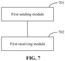
- FIG. 7 is a block diagram illustrating a device for pairing user devices according to an exemplary embodiment.
- the device may be implemented through software, hardware or a combination thereof to form a part or all of the electronic device.
- the device for pairing user devices is applied to a first user device.
- the device for pairing user devices may include a first sending module 701 and a first receiving module 702.
- the first sending module 701 is configured to send a pairing request message carrying a first identity to a core network.
- the first receiving module 702 is configured to receive a pairing response message that is fed back by the core network and carries a second identity of a second user device.
- the first user device is a UAV
- the second user device is a UAV controller
- the first user device is the UAV controller
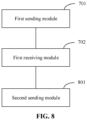
- the device may further include a second sending module 801.
- the second sending module 801 is configured to send a binding request message to the second user device according to the second identity.
- the second sending module 801 may further include a sending submodule 901.
- the second sending submodule 901 is configured to send the binding request message to the second user device according to the second identity through one of the following networks: a mobile cellular network and a near-field communication network.
- the device may further include a second receiving module 1001.
- the second receiving module 1001 is configured to receive a pairing response message that is fed back by the core network and carries response information indicating that pairing is rejected.
- the pairing request message is contained in attach request signaling; and the pairing response message is contained in attach accept signaling.
- FIG. 11 is a block diagram illustrating a device for pairing user devices according to an exemplary embodiment.
- the device may be implemented through software, hardware or a combination thereof to form a part or all of the electronic device.
- the device for pairing user devices is applied to a UTM side.
- the device for pairing user devices may include a first receiving module 1101, a querying module 1102 and a first sending module 1103.
- the first receiving module 1101 is configured to receive a query request message that is sent from a core network and carries a first identity of a first user device.
- the querying module 1102 is configured to query a second identity of a second user device in a correspondence between a UAV and a UAV controller.
- the second user device is the UAV controller
- the first user device is the UAV controller
- the second user device is the UAV.
- the first sending module 1103 is configured to feed, when a query result includes the second identity, a query response message carrying the second identity back to the core network.
- the device may further include a second sending module 1201.
- the second sending module 1201 is configured to feed, when the query result includes query failure information, a query response message carrying the query failure information back to the core network.
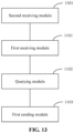
- the device may further include a second receiving module 1301.
- the second receiving module 1301 is configured to receive the correspondence, sent from a UAV manufacturer, between the UAV and the UAV controller.
- FIG. 14 is a block diagram illustrating a device for pairing user devices according to an exemplary embodiment.
- the device 1400 may be a mobile phone, a computer, a digital broadcast terminal, a messaging device, a gaming console, a tablet, a medical device, exercise equipment, a PDA, and the like.
- the device 1400 may include one or more of the following components: a processing component 1402, a memory 1404, a power component 1406, a multimedia component 1408, an audio component 1410, an Input/Output (I/O) interface 1414, a sensor component 1414, and a communication component 1416.
- a processing component 1402 a memory 1404, a power component 1406, a multimedia component 1408, an audio component 1410, an Input/Output (I/O) interface 1414, a sensor component 1414, and a communication component 1416.
- the processing component 1402 typically controls overall operations of the device 1400, such as the operations associated with display, telephone calls, data communications, camera operations, and recording operations.
- the processing component 1402 may include one or more processors 1420 to execute instructions to perform all or part of the operations in the above described methods.
- the processing component 1402 may include one or more modules which facilitate interaction between the processing component 1402 and other components.
- the processing component 1402 may include a multimedia module to facilitate interaction between the multimedia component 1408 and the processing component 1402.
- the memory 1404 is configured to store various types of data to support the operation of the device 1400. Examples of such data include instructions for any applications or methods operated on the device 1400, contact data, phonebook data, messages, pictures, video, etc.
- the memory 1404 may be implemented by using any type of volatile or non-volatile memory devices, or a combination thereof, such as a Static Random Access Memory (SRAM), an Electrically Erasable Programmable Read-Only Memory (EEPROM), an Erasable Programmable Read-Only Memory (EPROM), a Programmable Read-Only Memory (PROM), a Read-Only Memory (ROM), a magnetic memory, a flash memory, a magnetic or optical disk.
- SRAM Static Random Access Memory
- EEPROM Electrically Erasable Programmable Read-Only Memory
- EPROM Erasable Programmable Read-Only Memory
- PROM Programmable Read-Only Memory
- ROM Read-Only Memory
- magnetic memory a magnetic memory
- flash memory a flash memory
- the power component 1406 provides power to various components of the device 1400.
- the power component 1406 may include a power management system, one or more power sources, and any other components associated with the generation, management, and distribution of power in the device 1400.
- the multimedia component 1408 includes a screen providing an output interface between the device 1400 and the user.
- the screen may include a Liquid Crystal Display (LCD) and a Touch Panel (TP). If the screen includes the TP, the screen may be implemented as a touch screen to receive an input signal from the user.
- the TP includes one or more touch sensors to sense touches, swipes and gestures on the TP. The touch sensors may not only sense a boundary of a touch or swipe action, but also sense a period of time and a pressure associated with the touch or swipe action.
- the multimedia component 1408 includes a front camera and/or a rear camera. The front camera and/or the rear camera may receive external multimedia data when the device 1400 is in an operation mode, such as a photographing mode or a video mode. Each of the front camera and the rear camera may be a fixed optical lens system or have focus and optical zoom capability.
- the audio component 1410 is configured to output and/or input audio signals.
- the audio component 1410 includes a Microphone (MIC) configured to receive an external audio signal when the device 1400 is in an operation mode, such as a call mode, a recording mode, and a voice recognition mode.
- the received audio signal may further be stored in the memory 1404 or transmitted via the communication component 1416.
- the audio component 1410 further includes a speaker configured to output audio signals.
- the I/O interface 1414 provides an interface between the processing component 1402 and peripheral interface modules.
- the peripheral interface modules may be a keyboard, a click wheel, buttons, and the like.
- the buttons may include, but are not limited to, a home button, a volume button, a starting button, and a locking button.
- the sensor component 1414 includes one or more sensors to provide status assessments of various aspects of the device 1400.
- the sensor component 1414 may detect an on/off status of the device 1400 and relative positioning of components.
- the component is a display and small keyboard of the device 1400, and the sensor component 1414 may further detect a change in a position of the device 1400 or a component of the device 1400, presence or absence of contact between the user and the device 1400, orientation or acceleration/deceleration of the device 1400 and a change in temperature of the device 1400.
- the sensor component 1414 may include a proximity sensor, configured to detect the presence of nearby objects without any physical contact.
- the sensor component 1414 may also include a light sensor, such as a Complementary Metal Oxide Semiconductor (CMOS) or Charge Coupled Device (CCD) image sensor, configured for use in an imaging application.
- CMOS Complementary Metal Oxide Semiconductor
- CCD Charge Coupled Device
- the sensor component 1414 may also include an accelerometer sensor, a gyroscope sensor, a magnetic sensor, a pressure sensor, or a temperature sensor.
- the communication component 1416 is configured to facilitate wired or wireless communication between the device 1400 and other devices.
- the device 1400 may access a communication-standard-based wireless network, such as a Wireless Fidelity (WiFi) network, a 2nd-Generation (2G) or 3rd-Generation (3G) network or a combination thereof.
- WiFi Wireless Fidelity
- 2G 2nd-Generation
- 3G 3rd-Generation
- the communication component 1416 receives a broadcast signal or broadcast associated information from an external broadcast management system via a broadcast channel.
- the communication component 1416 further includes a near field communication (NFC) module to facilitate short-range communications.
- NFC near field communication
- the NFC module may be implemented based on a Radio Frequency Identification (RFID) technology, an Infrared Data Association (IrDA) technology, an Ultra-Wideband (UWB) technology, a Bluetooth (BT) technology, and other technologies.
- RFID Radio Frequency Identification
- IrDA Infrared Data Association
- UWB Ultra-Wideband
- BT Bluetooth
- the device 1400 may be implemented with one or more Application Specific Integrated Circuits (ASICs), Digital Signal Processors (DSPs), Digital Signal Processing Devices (DSPDs), Programmable Logic Devices (PLDs), Field Programmable Gate Arrays (FPGAs), controllers, micro-controllers, microprocessors, or other electronic components, for performing the above described methods.
- ASICs Application Specific Integrated Circuits
- DSPs Digital Signal Processors
- DSPDs Digital Signal Processing Devices
- PLDs Programmable Logic Devices
- FPGAs Field Programmable Gate Arrays
- controllers micro-controllers, microprocessors, or other electronic components, for performing the above described methods.
- a non-temporary computer readable storage medium including an instruction is further provided, for example, the memory 1404 including the instruction; and the instruction may be executed by the processor 1420 of the device 1400 to complete the above method.
- the non-transitory computer-readable storage medium may be a Read Only Memory (ROM), a Random Access Memory (RAM), a Compact Disc Read-Only Memory (CD-ROM), a magnetic tape, a floppy disc, an optical data storage device and the like.
- a device for pairing user devices which includes: a processor; and a memory, configured to store a processor-executable instruction.
- the processor is configured to: send a pairing request message carrying a first identity to a core network; and receive a pairing response message fed back by the core network and carrying a second identity of a second user device.
- the first user device is a UAV
- the second user device is a UAV controller
- the first user device is the UAV controller
- the processor may further be configured to: send a binding request message to the second user device according to the second identity.
- the processor may further be configured to, regarding sending the binding request message to the second user device according to the second identity, send the binding request message to the second user device according to the second identity through one of the following networks: a mobile cellular network and a near-field communication network.
- the processor may further be configured to receive a pairing response message fed back by the core network and carrying response information indicating that pairing is rejected.
- the processor may further be configured to contain the pairing request message in attach request signaling; and contain the pairing response message in attach accept signaling.
- a computer-readable storage medium is provided, an instruction in the storage medium when executed by a processor of a device, enables the device to execute the method for pairing user devices.
- the method may include the following operations.
- a pairing request message carrying a first identity is sent to a core network.
- a pairing response message fed back by the core network and carrying a second identity of a second user device is received.
- the first user device is a UAV
- the second user device is a UAV controller
- the first user device is the UAV controller
- the second user device is the UAV.
- the instruction in the storage medium may further include sending a binding request message to the second user device according to the second identity.
- the instruction in the storage medium may further include, regarding sending the binding request message to the second user device according to the second identity, sending a binding request message to the second user device according to the second identity through one of the following networks: a mobile cellular network and a near-field communication network.
- the instruction in the storage medium may further include: receiving a pairing response message fed back by the core network and carrying response information indicating that pairing is rejected.
- the instruction in the storage medium may further include: containing the pairing request message in attach request signaling; and containing the pairing response message in attach accept signaling.
- FIG. 15 is a block diagram illustrating a device 1500 for synchronizing data according to an exemplary embodiment.
- the device 1500 may be provided as a computer.
- the device 1500 includes a processing component 1522, which further includes one or more processors, and a memory resource represented by a memory 1532 and configured to store an instruction that may be executed by the processing component 1522, such as an application program.
- the application program stored in the memory 1532 may include one or more modules, with each module corresponding to one set of instructions.
- the processing component 1522 is configured to execute the instruction to the above method for synchronizing data.
- the device 1500 may further include a power component 1526, configured to execute power management of the device 1500, a wired or wireless network interface 1550 configured to connect the device 1500 to the network, and an I/O interface 1558.
- the device 1500 may be operated based on an operating system stored in the memory 1532, for example, Windows ServerTM, Mac OS XTM, UnixTM, LinuxTM, FreeBSDTM or the like.
- a device for pairing user devices may include: a processor; and a memory, configured to store a processor-executable instruction.
- the processor is configured to: receive a pairing request message sent from a first user device and carrying a first identity, the first user device being a UAV or a UAV controller; send a query request message carrying the first identity to a UTM; receive a query response message fed back by the UTM and including a query result; and send, when the query result includes a second identity of a second user device in a correspondence between the UAV and the UAV controller, a pairing response message carrying the second identity to the first user device.
- the first user device is the UAV
- the second user device is the UAV controller
- the first user device is the UAV controller
- the second user device is the UAV.
- the processor may further be configured to enable the pairing request message to be contained in attach request signaling; and the pairing response message to be contained in attach accept signaling.
- the processor may further be configured to: enable, when the query result includes query failure information, the pairing response message to carry response information indicating that pairing is rejected.
- a computer-readable storage medium is provided.
- An instruction in the storage medium when executed by a processor of a device, enables the device to execute the above method for pairing user devices.
- the method may include the following operations.
- a pairing request message sent from a first user device and carrying a first identity is received.
- the first user device includes a UAV or a UAV controller.
- a query request message carrying the first identity is sent to a UTM.
- a query response message fed back by the UTM and containing a query result is received.
- a pairing response message carrying the second identity is sent to the first user device.
- the first user device is the UAV
- the second user device is the UAV controller
- the first user device is the UAV controller
- the instruction in the storage medium may further include containing the pairing request message in attach request signaling; and containing the pairing response message in attach accept signaling.
- the instruction in the storage medium may further include, when the query result includes query failure information, the pairing response message carries response information indicating that the pairing is rejected.
- a device for pairing user devices may include: a processor; and a memory, configured to store a processor-executable instruction.
- the processor is configured to: receive a query request message sent from a core network and carrying a first identity of a first user device; query a second identity of a second user device in a correspondence between a UAV and a UAV controller, wherein when the first user is the UAV, the second user device is the UAV controller, where when the first user device is the UAV controller, the second user device is the UAV; and feed, when a query result includes the second identity, a query response message carrying the second identity back to the core network.
- the processor may further be configured to: when the query result includes query failure information, feed a query response message carrying the query failure information back to the core network.
- the processor may further be configured to receive the correspondence, sent from a UAV manufacturer, between the UAV and the UAV controller.
- a computer-readable storage medium is provided.
- An instruction in the storage medium when executed by a processor of a device, enables the device to execute the above method for pairing user devices.
- the method may include the following operations.
- a query request message sent from a core network and carrying a first identity of a first user device is received.
- a second identity of a second user device in a correspondence between a UAV and a UAV controller is queried.
- the first user is the UAV
- the second user device is the UAV controller
- the first user device is the UAV controller
- a query response message carrying the second identity is fed back to the core network.
- the instruction in the storage medium may further include: when the query result includes query failure information, feeding a query response message carrying the query failure information back to the core network.
- the instruction in the storage medium may further include: receiving the correspondence, sent from a UAV manufacturer, between the UAV and the UAV controller.
Landscapes
- Engineering & Computer Science (AREA)
- Computer Networks & Wireless Communication (AREA)
- Signal Processing (AREA)
- Computer Security & Cryptography (AREA)
- Aviation & Aerospace Engineering (AREA)
- Physics & Mathematics (AREA)
- General Physics & Mathematics (AREA)
- Mobile Radio Communication Systems (AREA)
- Selective Calling Equipment (AREA)
Claims (14)
- Verfahren zum Koppeln von Nutzergeräten, wobei die Nutzergeräte ein unbemanntes Luftfahrzeug, UAV, und eine UAV-Steuerung umfassen, wobei das Verfahren auf eine Vorrichtung in einem Kernnetzwerk angewendet wird, wobei das Verfahren umfasst:Empfangen einer Kopplungsanforderungsnachricht, die von einer ersten Nutzervorrichtung gesendet wird und eine erste Identität (101) der ersten Nutzervorrichtung trägt, wobei die erste Nutzervorrichtung das unbemannte Luftfahrzeug UAV oder die UAV-Steuerung umfasst;gekennzeichnet durch Senden einer Abfrageanforderungsnachricht, die die erste Identität trägt, an ein unbemanntes Luftfahrzeugsystem, UAS, Verkehrsmanagement, UTM (102), um eine Abfrage einer zweiten Identität einer zweiten Benutzervorrichtung anzufordern, die der ersten Identität in einer Korrespondenz zwischen einem UAV und einer UAV-Steuerung entspricht, wobei das UTM keine Vorrichtung in dem Kernnetzwerk ist, die Korrespondenz zwischen dem UAV und der UAV-Steuerung durch einen UAV-Hersteller im Voraus in dem UTM gespeichert ist;Empfangen einer Abfrageantwortnachricht, die von dem UTM zurückgespeist wird und ein Abfrageergebnis enthält (103); undSenden, wenn das Abfrageergebnis die zweite Identität des zweiten Nutzergeräts in der Korrespondenz zwischen dem UAV und der UAV-Steuerung umfasst, einer Kopplungsantwortnachricht, die die zweite Identität zum ersten Nutzergerät trägt (104), wobei, wenn das erste Nutzergerät das UAV ist, das zweite Nutzergerät die UAV-Steuerung ist, und während das erste Nutzergerät die UAV-Steuerung ist, das zweite Nutzergerät das UAV ist.
- Verfahren nach Anspruch 1, wobei die Kopplungsanforderungsnachricht in einer Anschlussanforderungssignalisierung enthalten ist und die Kopplungsantwortnachricht in einer Anschlussakzeptanzsignalisierung enthalten ist.
- Verfahren nach Anspruch 1 oder 2, wobei, wenn das Abfrageergebnis Abfragefehlerinformationen umfasst, die Kopplungsantwortnachricht Antwortinformationen trägt, die anzeigen, dass die Kopplung abgelehnt wird.
- Verfahren zum Koppeln von Nutzergeräten, wobei die Nutzergeräte ein unbemanntes Luftfahrzeug, UAV, und eine UAV-Steuerung umfassen, wobei das Verfahren auf ein erstes der Geräte angewendet wird, wobei das Verfahren umfasst:Senden einer Kopplungsanforderungsnachricht, die eine erste Identität des ersten Nutzergeräts trägt, an ein Gerät in einem Kernnetzwerk (201); undgekennzeichnet durch Empfangen einer Kopplungsantwortnachricht, die von dem Gerät in dem Kernnetzwerk zurückgespeist wird und eine zweite Identität eines zweiten der Nutzergeräte (202) trägt, wobei in dem Fall, in dem das erste Nutzergerät ein unbemanntes Luftfahrzeug, UAV, ist, das zweite Nutzergerät eine UAV-Steuerung ist, und in dem Fall, in dem das erste Nutzergerät die UAV-Steuerung ist, das zweite Nutzergerät das UAV ist.
- Verfahren nach Anspruch 4, ferner umfassend:
Senden einer Bindungsanforderungsnachricht an das zweite Nutzergerät gemäß der zweiten Identität (303). - Verfahren nach Anspruch 5, wobei das Senden der Bindungsanforderungsnachricht an das zweite Nutzergerät gemäß der zweiten Identität (303) umfasst:
Senden der Bindungsanforderungsnachricht an das zweite Nutzergerät gemäß der zweiten Identität über eines der folgenden Netzwerke: das Mobilfunknetz und ein Nahfeldkommunikationsnetzwerk. - Verfahren nach einem der Ansprüche 4 bis 6, ferner umfassend:
Empfangen einer Kopplungsantwortnachricht, die von der Vorrichtung in dem Kernnetzwerk zurückgespeist wird und Antwortinformationen trägt, die angeben, dass die Kopplung abgelehnt wird. - Verfahren nach einem der Ansprüche 4 bis 7, wobei die Kopplungsanforderungsnachricht in einer Anschlussanfrage-Signalisierung enthalten ist und die Kopplungsantwortnachricht in einer Abschlussakzeptanz-Signalisierung enthalten ist.
- Verfahren zum Koppeln von Nutzergeräten, wobei die Nutzergeräte ein unbemanntes Luftfahrzeug, UAV, und eine UAV-Steuerung umfassen, wobei das Verfahren auf ein unbemanntes Luftfahrzeugsystem, UAS, Verkehrsmanagement, UTM, angewendet wird, dadurch gekennzeichnet, dass das Verfahren umfasst:Empfangen einer Abfrageanforderungsnachricht, die von einem Gerät in einem Kernnetzwerk gesendet wird und eine erste Identität eines ersten der Nutzergeräte (401) trägt;Abfragen einer zweiten Identität eines zweiten der Nutzergeräte, die der ersten Identität in einer Korrespondenz zwischen einem unbemannten Luftfahrzeug (UAV) und einer UAV-Steuerung (402) entspricht, wobei das UTM keine Vorrichtung in dem Kernnetzwerk ist, die Korrespondenz zwischen dem UAV und der UAV-Steuerung durch einen UAV-Hersteller im Voraus in dem UTM gespeichert ist, und wobei in dem Fall, dass der erste Nutzer das UAV ist, das zweite Nutzergerät die UAV-Steuerung ist, und in dem Fall, dass das erste Nutzergerät die UAV-Steuerung ist, das zweite Nutzergerät die UAV ist; undWenn ein Abfrageergebnis die zweite Identität umfasst, zurückgeben einer Abfrageantwortnachricht, die die zweite Identität trägt, an die Vorrichtung in dem Kernnetzwerk (403).
- Verfahren nach Anspruch 9, ferner umfassend:
wenn das Abfrageergebnis Abfragefehlerinformationen umfasst, Zurücksenden einer Abfrageantwortnachricht, die die Abfragefehlerinformationen trägt, an die Vorrichtung in dem Kernnetzwerk. - Vorrichtung in einem Kernnetzwerk zum Koppeln von Nutzergeräten, wobei das Nutzergerät ein unbemanntes Luftfahrzeug, UAV, und eine UAV-Steuerung umfasst, wobei die Vorrichtung umfasst:ein erstes Empfangsmodul, das dazu konfiguriert ist, eine Kopplungsanforderungsnachricht zu empfangen, die von einem ersten der Nutzergeräte gesendet wird und eine erste Identität des ersten Nutzergeräts trägt, wobei das erste Nutzergerät ein unbemanntes Luftfahrzeug (UAV) oder eine UAV-Steuerung umfasst;dadurch gekennzeichnet, dass die Vorrichtung ferner ein erstes Sendemodul umfasst, das dazu konfiguriert ist, eine Abfrageanforderungsnachricht, die die erste Identität trägt, an ein unbemanntes Luftfahrzeugsystem UAS-Verkehrsmanagement, UTM, zu senden, um eine Abfrage einer zweiten Identität eines zweiten Nutzergeräts anzufordern, das der ersten Identität in einer Korrespondenz zwischen einem UAV und einer UAV-Steuerung entspricht, wobei das UTM keine Vorrichtung in dem Kernnetzwerk ist, die Korrespondenz zwischen dem UAV und der UAV-Steuerung durch einen UAV-Hersteller im Voraus in dem UTM gespeichert ist;ein zweites Empfangsmodul, das dazu konfiguriert ist, eine Abfrageantwortnachricht zu empfangen, die von dem UTM zurückgespeist wird und ein Abfrageergebnis enthält; undein zweites Sendemodul, das dazu konfiguriert ist, wenn das Abfrageergebnis die zweite Identität des zweiten Nutzergeräts in der Korrespondenz zwischen dem UAV und der UAV-Steuerung umfasst, eine Kopplungsantwortnachricht, die die zweite Identität trägt, an das erste Nutzergerät zu senden, wobei in dem Fall, dass das erste Nutzergerät das UAV ist, das zweite Nutzergerät die UAV-Steuerung ist, und in dem Fall, dass das erste Nutzergerät die UAV-Steuerung ist, das zweite Nutzergerät das UAV ist.
- Vorrichtung in einem ersten Nutzergerät zum Koppeln von Nutzergeräten, wobei das Nutzergerät ein unbemanntes Luftfahrzeug, UAV, und eine UAV-Steuerung umfasst, wobei die Vorrichtung umfasst:ein erstes Sendemodul, das dazu konfiguriert ist, eine Kopplungsanforderungsnachricht, die eine erste Identität des ersten Nutzergeräts trägt, an ein Gerät in einem Kernnetzwerk zu senden; unddadurch gekennzeichnet, dass die Vorrichtung ferner ein erstes Empfangsmodul umfasst, das dazu konfiguriert ist, eine Kopplungsantwortnachricht zu empfangen, die von der Vorrichtung in dem Kernnetzwerk zurückgespeist wird und eine zweite Identität eines der Nutzergeräte trägt, wobei in dem Fall, in dem das erste Nutzergerät ein unbemanntes Luftfahrzeug (UAV) ist, das zweite Nutzergerät eine UAV-Steuerung ist, und in dem Fall, in dem das erste Nutzergerät die UAV-Steuerung ist, das zweite Nutzergerät das UAV ist.
- Vorrichtung in einem unbemannten Luftfahrzeugsystem, UAS, Verkehrsmanagement, UTM, zur Kopplung von Nutzergeräten, wobei die Nutzergeräte ein unbemanntes Luftfahrzeug, UAV, und eine UAV-Steuerung umfassen, dadurch gekennzeichnet, dass die Vorrichtung umfasst:ein erstes Empfangsmodul, das dazu konfiguriert ist, eine Abfrageanforderungsnachricht zu empfangen, die von einem Gerät in einem Kernnetzwerk gesendet wird und eine erste Identität eines ersten der Nutzergeräte trägt;ein Abfragemodul, das dazu konfiguriert ist, eine zweite Identität eines zweiten der Nutzergeräte abzufragen, die der ersten Identität in einer Entsprechung zwischen einem unbemannten Luftfahrzeug (UAV) und einer UAV-Steuerung entspricht, wobei das UTM keine Vorrichtung in dem Kernnetzwerk ist, die Entsprechung zwischen dem UAV und der UAV-Steuerung durch einen UAV-Hersteller im Voraus in dem UTM gespeichert ist, und wobei in dem Fall, dass der erste Nutzer das UAV ist, das zweite Nutzergerät die UAV-Steuerung ist, und in dem Fall, dass das erste Nutzergerät die UAV-Steuerung ist, das zweite Nutzergerät das UAV ist; undein erstes Sendemodul, das dazu konfiguriert ist, wenn ein Abfrageergebnis die zweite Identität umfasst, eine Abfrageantwortnachricht, die die zweite Identität trägt, zurück an die Vorrichtung in dem Kernnetzwerk zu senden.
- Computerlesbares Speichermedium, auf dem ein Computerbefehl gespeichert ist, der, wenn er von einem Prozessor ausgeführt wird, das Verfahren nach einem der Ansprüche 1 bis 3 implementiert.
Applications Claiming Priority (1)
| Application Number | Priority Date | Filing Date | Title |
|---|---|---|---|
| PCT/CN2018/121555 WO2020124321A1 (zh) | 2018-12-17 | 2018-12-17 | 用户设备配对的方法及装置 |
Publications (3)
| Publication Number | Publication Date |
|---|---|
| EP3893594A1 EP3893594A1 (de) | 2021-10-13 |
| EP3893594A4 EP3893594A4 (de) | 2022-07-27 |
| EP3893594B1 true EP3893594B1 (de) | 2025-06-25 |
Family
ID=66500774
Family Applications (1)
| Application Number | Title | Priority Date | Filing Date |
|---|---|---|---|
| EP18943694.2A Active EP3893594B1 (de) | 2018-12-17 | 2018-12-17 | Benutzervorrichtungpaarungsverfahren und -einrichtung |
Country Status (4)
| Country | Link |
|---|---|
| US (1) | US11805562B2 (de) |
| EP (1) | EP3893594B1 (de) |
| CN (1) | CN109792786A (de) |
| WO (1) | WO2020124321A1 (de) |
Families Citing this family (5)
| Publication number | Priority date | Publication date | Assignee | Title |
|---|---|---|---|---|
| CN114514766B (zh) * | 2019-08-23 | 2026-03-20 | 交互数字专利控股公司 | 用于无人机系统(uas)标识、绑定和配对的方法和装置 |
| WO2021174464A1 (en) * | 2020-03-04 | 2021-09-10 | Guangdong Oppo Mobile Telecommunications Corp., Ltd. | Method and device for allocating identity, and communication device |
| WO2021195900A1 (zh) * | 2020-03-30 | 2021-10-07 | 华为技术有限公司 | 一种终端设备的验证方法及装置 |
| CN112637845B (zh) * | 2020-12-18 | 2022-07-26 | 深圳市赛为智能股份有限公司 | 无人机交互认证方法、装置、计算机设备及存储介质 |
| KR20250140571A (ko) * | 2023-02-23 | 2025-09-25 | 지티이 코포레이션 | 무인 자율주행 차량들과의 바인딩 정보 송신을 위한 시스템 및 방법 |
Family Cites Families (13)
| Publication number | Priority date | Publication date | Assignee | Title |
|---|---|---|---|---|
| US20110103293A1 (en) * | 2009-10-30 | 2011-05-05 | Paragon Communication Solutions, Inc. | Internet based partitioning wireless communication system |
| CN103037428B (zh) * | 2011-09-29 | 2017-09-19 | 北京三星通信技术研究有限公司 | 一种实现mdt测量匿名汇报的方法 |
| JP6133506B2 (ja) * | 2014-04-17 | 2017-05-24 | エスゼット ディージェイアイ テクノロジー カンパニー リミテッドSz Dji Technology Co.,Ltd | 飛行制限区域に対する飛行制御 |
| US9905134B2 (en) * | 2015-02-12 | 2018-02-27 | Aerobotic Innovations, LLC | System and method of preventing and remedying restricted area intrusions by unmanned aerial vehicles |
| CN107409051B (zh) | 2015-03-31 | 2021-02-26 | 深圳市大疆创新科技有限公司 | 用于生成飞行管制的认证系统和方法 |
| CN106100721B (zh) * | 2016-06-24 | 2019-03-01 | 广州极飞科技有限公司 | 对无人机和遥控器配对的方法、服务器、遥控器及系统 |
| CN108496333B (zh) * | 2017-03-30 | 2021-07-20 | 深圳市大疆创新科技有限公司 | 配对方法、设备、机器可读存储介质以及系统 |
| WO2018178750A1 (en) | 2017-03-31 | 2018-10-04 | Telefonaktiebolaget Lm Ericsson (Publ) | Methods and systems for enabling a reliable flight recorder system in unmanned traffic management systems |
| WO2019024053A1 (zh) * | 2017-08-03 | 2019-02-07 | 北京小米移动软件有限公司 | 无人机控制方法及装置、无人机和遥控设备 |
| CN109451810B (zh) * | 2017-08-11 | 2021-08-24 | 北京小米移动软件有限公司 | 无人机控制方法及装置、无人机和核心网设备 |
| CN108064360A (zh) * | 2017-11-02 | 2018-05-22 | 北京小米移动软件有限公司 | 无人机的控制方法及装置 |
| CN108093403A (zh) * | 2017-12-12 | 2018-05-29 | 北京小米移动软件有限公司 | 接入无线网络的方法、装置及存储介质 |
| CN109059900A (zh) * | 2018-08-30 | 2018-12-21 | 深圳市研本品牌设计有限公司 | 高空玻璃清洗无人机的定位方法及系统 |
-
2018
- 2018-12-17 EP EP18943694.2A patent/EP3893594B1/de active Active
- 2018-12-17 WO PCT/CN2018/121555 patent/WO2020124321A1/zh not_active Ceased
- 2018-12-17 US US17/414,929 patent/US11805562B2/en active Active
- 2018-12-17 CN CN201880002845.0A patent/CN109792786A/zh active Pending
Non-Patent Citations (2)
| Title |
|---|
| INTEL: "FS_ID_UAS: Update Definition and Use case 5.1", vol. SA WG1, no. West Palm Beach, Florida USA; 20180820 - 20180824, 10 August 2018 (2018-08-10), XP051534776, Retrieved from the Internet <URL:http://www.3gpp.org/ftp/tsg%5Fsa/WG1%5FServ/TSGS1%5F83%5FWPalmBeach/Docs/S1%2D182298%2Ezip> [retrieved on 20180810] * |
| INTEL: "FS_ID_UAS: Use case for UAS Discovery", vol. SA WG1, no. West Palm Beach, Florida USA; 20180820 - 20180824, 10 August 2018 (2018-08-10), XP051534777, Retrieved from the Internet <URL:http://www.3gpp.org/ftp/tsg%5Fsa/WG1%5FServ/TSGS1%5F83%5FWPalmBeach/Docs/S1%2D182299%2Ezip> [retrieved on 20180810] * |
Also Published As
| Publication number | Publication date |
|---|---|
| EP3893594A1 (de) | 2021-10-13 |
| WO2020124321A1 (zh) | 2020-06-25 |
| EP3893594A4 (de) | 2022-07-27 |
| US20220070949A1 (en) | 2022-03-03 |
| US11805562B2 (en) | 2023-10-31 |
| CN109792786A (zh) | 2019-05-21 |
Similar Documents
| Publication | Publication Date | Title |
|---|---|---|
| US11985620B2 (en) | Network registration method and apparatus | |
| EP3893594B1 (de) | Benutzervorrichtungpaarungsverfahren und -einrichtung | |
| US12137495B2 (en) | Inactivity timer control method and device | |
| CN109451877B (zh) | 无人机控制方法及装置、无人机和遥控设备 | |
| US11178700B2 (en) | Unmanned aerial vehicle management method and apparatus, and communication connection establishment method and apparatus | |
| US12126566B2 (en) | System information reception method and apparatus, and system information transmission method and apparatus | |
| EP3836422B1 (de) | Flugpfadkonfigurationsverfahren und -vorrichtung | |
| EP3790298B1 (de) | Verfahren zum erfassen und senden von routeninformationen eines unbemannten luftfahrzeuges | |
| US20210298113A1 (en) | Method and device for transmitting flight information | |
| CN115843451B (zh) | 按需定位参考信号请求方法及装置、存储介质 | |
| EP3751907B1 (de) | Drohnenkennungsverfahren und -vorrichtung | |
| US12432808B2 (en) | Request information sending method and device, and request information receiving method and device | |
| EP4404688A1 (de) | Verfahren und vorrichtung zur kapazitätsmeldung und speichermedium | |
| EP4300125A1 (de) | Entfernungsmessungsverfahren und -vorrichtung sowie benutzergerät und speichermedium | |
| CN115552947B (zh) | 原因确定方法和装置、原因指示方法和装置 | |
| US20210295712A1 (en) | Method and device for configuring flight path | |
| CN115191134B (zh) | 用户寻呼分组的确定方法、装置、用户设备及存储介质 | |
| WO2022193191A1 (zh) | 资源配置方法、装置、终端设备、接入网设备及存储介质 | |
| WO2022052070A1 (zh) | 连接控制方法、连接控制装置 | |
| EP3751951A1 (de) | Verfahren, vorrichtung und system zur herstellung einer verbindung zwischen einem endgerät und einem kernnetzwerk, auf das zugegriffen werden soll | |
| CN114223300B (zh) | 基于辅助资源集进行通信的方法、装置及存储介质 | |
| CN118301550A (zh) | 定位方法、装置、电子设备及存储介质 | |
| WO2022222086A1 (zh) | 信息传输方法、装置、用户设备、接入网设备、核心网及存储介质 | |
| CN117882471A (zh) | 资源配置方法、装置、存储介质以及终端 | |
| CN116267030A (zh) | 测距能力开放的方法、装置、通信设备及存储介质 |
Legal Events
| Date | Code | Title | Description |
|---|---|---|---|
| STAA | Information on the status of an ep patent application or granted ep patent |
Free format text: STATUS: THE INTERNATIONAL PUBLICATION HAS BEEN MADE |
|
| PUAI | Public reference made under article 153(3) epc to a published international application that has entered the european phase |
Free format text: ORIGINAL CODE: 0009012 |
|
| STAA | Information on the status of an ep patent application or granted ep patent |
Free format text: STATUS: REQUEST FOR EXAMINATION WAS MADE |
|
| 17P | Request for examination filed |
Effective date: 20210709 |
|
| AK | Designated contracting states |
Kind code of ref document: A1 Designated state(s): AL AT BE BG CH CY CZ DE DK EE ES FI FR GB GR HR HU IE IS IT LI LT LU LV MC MK MT NL NO PL PT RO RS SE SI SK SM TR |
|
| DAV | Request for validation of the european patent (deleted) | ||
| DAX | Request for extension of the european patent (deleted) | ||
| A4 | Supplementary search report drawn up and despatched |
Effective date: 20220629 |
|
| RIC1 | Information provided on ipc code assigned before grant |
Ipc: B64C 39/02 20060101ALI20220623BHEP Ipc: H04W 12/06 20210101ALI20220623BHEP Ipc: H04W 76/14 20180101ALI20220623BHEP Ipc: H04W 76/11 20180101AFI20220623BHEP |
|
| STAA | Information on the status of an ep patent application or granted ep patent |
Free format text: STATUS: EXAMINATION IS IN PROGRESS |
|
| 17Q | First examination report despatched |
Effective date: 20240206 |
|
| GRAP | Despatch of communication of intention to grant a patent |
Free format text: ORIGINAL CODE: EPIDOSNIGR1 |
|
| STAA | Information on the status of an ep patent application or granted ep patent |
Free format text: STATUS: GRANT OF PATENT IS INTENDED |
|
| INTG | Intention to grant announced |
Effective date: 20250402 |
|
| GRAS | Grant fee paid |
Free format text: ORIGINAL CODE: EPIDOSNIGR3 |
|
| GRAA | (expected) grant |
Free format text: ORIGINAL CODE: 0009210 |
|
| STAA | Information on the status of an ep patent application or granted ep patent |
Free format text: STATUS: THE PATENT HAS BEEN GRANTED |
|
| P01 | Opt-out of the competence of the unified patent court (upc) registered |
Free format text: CASE NUMBER: APP_21156/2025 Effective date: 20250505 |
|
| AK | Designated contracting states |
Kind code of ref document: B1 Designated state(s): AL AT BE BG CH CY CZ DE DK EE ES FI FR GB GR HR HU IE IS IT LI LT LU LV MC MK MT NL NO PL PT RO RS SE SI SK SM TR |
|
| REG | Reference to a national code |
Ref country code: GB Ref legal event code: FG4D |
|
| REG | Reference to a national code |
Ref country code: CH Ref legal event code: EP |
|
| REG | Reference to a national code |
Ref country code: DE Ref legal event code: R096 Ref document number: 602018083072 Country of ref document: DE |
|
| REG | Reference to a national code |
Ref country code: CH Ref legal event code: EP |
|
| REG | Reference to a national code |
Ref country code: IE Ref legal event code: FG4D |
|
| REG | Reference to a national code |
Ref country code: NL Ref legal event code: FP |
|
| PG25 | Lapsed in a contracting state [announced via postgrant information from national office to epo] |
Ref country code: FI Free format text: LAPSE BECAUSE OF FAILURE TO SUBMIT A TRANSLATION OF THE DESCRIPTION OR TO PAY THE FEE WITHIN THE PRESCRIBED TIME-LIMIT Effective date: 20250625 |
|
| REG | Reference to a national code |
Ref country code: LT Ref legal event code: MG9D |
|
| PG25 | Lapsed in a contracting state [announced via postgrant information from national office to epo] |
Ref country code: NO Free format text: LAPSE BECAUSE OF FAILURE TO SUBMIT A TRANSLATION OF THE DESCRIPTION OR TO PAY THE FEE WITHIN THE PRESCRIBED TIME-LIMIT Effective date: 20250925 Ref country code: GR Free format text: LAPSE BECAUSE OF FAILURE TO SUBMIT A TRANSLATION OF THE DESCRIPTION OR TO PAY THE FEE WITHIN THE PRESCRIBED TIME-LIMIT Effective date: 20250926 |
|
| PG25 | Lapsed in a contracting state [announced via postgrant information from national office to epo] |
Ref country code: BG Free format text: LAPSE BECAUSE OF FAILURE TO SUBMIT A TRANSLATION OF THE DESCRIPTION OR TO PAY THE FEE WITHIN THE PRESCRIBED TIME-LIMIT Effective date: 20250625 |
|
| PG25 | Lapsed in a contracting state [announced via postgrant information from national office to epo] |
Ref country code: HR Free format text: LAPSE BECAUSE OF FAILURE TO SUBMIT A TRANSLATION OF THE DESCRIPTION OR TO PAY THE FEE WITHIN THE PRESCRIBED TIME-LIMIT Effective date: 20250625 |
|
| PG25 | Lapsed in a contracting state [announced via postgrant information from national office to epo] |
Ref country code: RS Free format text: LAPSE BECAUSE OF FAILURE TO SUBMIT A TRANSLATION OF THE DESCRIPTION OR TO PAY THE FEE WITHIN THE PRESCRIBED TIME-LIMIT Effective date: 20250925 |
|
| PG25 | Lapsed in a contracting state [announced via postgrant information from national office to epo] |
Ref country code: LV Free format text: LAPSE BECAUSE OF FAILURE TO SUBMIT A TRANSLATION OF THE DESCRIPTION OR TO PAY THE FEE WITHIN THE PRESCRIBED TIME-LIMIT Effective date: 20250625 |
|
| PG25 | Lapsed in a contracting state [announced via postgrant information from national office to epo] |
Ref country code: PT Free format text: LAPSE BECAUSE OF FAILURE TO SUBMIT A TRANSLATION OF THE DESCRIPTION OR TO PAY THE FEE WITHIN THE PRESCRIBED TIME-LIMIT Effective date: 20251027 |
|
| REG | Reference to a national code |
Ref country code: AT Ref legal event code: MK05 Ref document number: 1808020 Country of ref document: AT Kind code of ref document: T Effective date: 20250625 |
|
| PG25 | Lapsed in a contracting state [announced via postgrant information from national office to epo] |
Ref country code: IS Free format text: LAPSE BECAUSE OF FAILURE TO SUBMIT A TRANSLATION OF THE DESCRIPTION OR TO PAY THE FEE WITHIN THE PRESCRIBED TIME-LIMIT Effective date: 20251025 |
|
| PGFP | Annual fee paid to national office [announced via postgrant information from national office to epo] |
Ref country code: GB Payment date: 20251211 Year of fee payment: 8 |
|
| PG25 | Lapsed in a contracting state [announced via postgrant information from national office to epo] |
Ref country code: AT Free format text: LAPSE BECAUSE OF FAILURE TO SUBMIT A TRANSLATION OF THE DESCRIPTION OR TO PAY THE FEE WITHIN THE PRESCRIBED TIME-LIMIT Effective date: 20250625 Ref country code: SM Free format text: LAPSE BECAUSE OF FAILURE TO SUBMIT A TRANSLATION OF THE DESCRIPTION OR TO PAY THE FEE WITHIN THE PRESCRIBED TIME-LIMIT Effective date: 20250625 |
|
| PGFP | Annual fee paid to national office [announced via postgrant information from national office to epo] |
Ref country code: FR Payment date: 20251212 Year of fee payment: 8 Ref country code: NL Payment date: 20251217 Year of fee payment: 8 |
|
| PG25 | Lapsed in a contracting state [announced via postgrant information from national office to epo] |
Ref country code: CZ Free format text: LAPSE BECAUSE OF FAILURE TO SUBMIT A TRANSLATION OF THE DESCRIPTION OR TO PAY THE FEE WITHIN THE PRESCRIBED TIME-LIMIT Effective date: 20250625 |
|
| PG25 | Lapsed in a contracting state [announced via postgrant information from national office to epo] |
Ref country code: PL Free format text: LAPSE BECAUSE OF FAILURE TO SUBMIT A TRANSLATION OF THE DESCRIPTION OR TO PAY THE FEE WITHIN THE PRESCRIBED TIME-LIMIT Effective date: 20250625 |
|
| PG25 | Lapsed in a contracting state [announced via postgrant information from national office to epo] |
Ref country code: EE Free format text: LAPSE BECAUSE OF FAILURE TO SUBMIT A TRANSLATION OF THE DESCRIPTION OR TO PAY THE FEE WITHIN THE PRESCRIBED TIME-LIMIT Effective date: 20250625 |
|
| PG25 | Lapsed in a contracting state [announced via postgrant information from national office to epo] |
Ref country code: SK Free format text: LAPSE BECAUSE OF FAILURE TO SUBMIT A TRANSLATION OF THE DESCRIPTION OR TO PAY THE FEE WITHIN THE PRESCRIBED TIME-LIMIT Effective date: 20250625 |
|
| PG25 | Lapsed in a contracting state [announced via postgrant information from national office to epo] |
Ref country code: ES Free format text: LAPSE BECAUSE OF FAILURE TO SUBMIT A TRANSLATION OF THE DESCRIPTION OR TO PAY THE FEE WITHIN THE PRESCRIBED TIME-LIMIT Effective date: 20250625 |
|
| PG25 | Lapsed in a contracting state [announced via postgrant information from national office to epo] |
Ref country code: RO Free format text: LAPSE BECAUSE OF FAILURE TO SUBMIT A TRANSLATION OF THE DESCRIPTION OR TO PAY THE FEE WITHIN THE PRESCRIBED TIME-LIMIT Effective date: 20250625 |
|
| PG25 | Lapsed in a contracting state [announced via postgrant information from national office to epo] |
Ref country code: DK Free format text: LAPSE BECAUSE OF FAILURE TO SUBMIT A TRANSLATION OF THE DESCRIPTION OR TO PAY THE FEE WITHIN THE PRESCRIBED TIME-LIMIT Effective date: 20250625 |
|
| PG25 | Lapsed in a contracting state [announced via postgrant information from national office to epo] |
Ref country code: IT Free format text: LAPSE BECAUSE OF FAILURE TO SUBMIT A TRANSLATION OF THE DESCRIPTION OR TO PAY THE FEE WITHIN THE PRESCRIBED TIME-LIMIT Effective date: 20250625 |
|
| PLBE | No opposition filed within time limit |
Free format text: ORIGINAL CODE: 0009261 |
|
| STAA | Information on the status of an ep patent application or granted ep patent |
Free format text: STATUS: NO OPPOSITION FILED WITHIN TIME LIMIT |