EP3893686B1 - Carte pour article chaussant - Google Patents
Carte pour article chaussant Download PDFInfo
- Publication number
- EP3893686B1 EP3893686B1 EP19896186.4A EP19896186A EP3893686B1 EP 3893686 B1 EP3893686 B1 EP 3893686B1 EP 19896186 A EP19896186 A EP 19896186A EP 3893686 B1 EP3893686 B1 EP 3893686B1
- Authority
- EP
- European Patent Office
- Prior art keywords
- protuberance
- anterior
- outsole
- posterior
- map
- Prior art date
- Legal status (The legal status is an assumption and is not a legal conclusion. Google has not performed a legal analysis and makes no representation as to the accuracy of the status listed.)
- Active
Links
Images


Classifications
-
- A—HUMAN NECESSITIES
- A43—FOOTWEAR
- A43B—CHARACTERISTIC FEATURES OF FOOTWEAR; PARTS OF FOOTWEAR
- A43B21/00—Heels; Top-pieces or top-lifts
- A43B21/24—Heels; Top-pieces or top-lifts characterised by the constructive form
-
- A—HUMAN NECESSITIES
- A43—FOOTWEAR
- A43B—CHARACTERISTIC FEATURES OF FOOTWEAR; PARTS OF FOOTWEAR
- A43B13/00—Soles; Sole-and-heel integral units
- A43B13/14—Soles; Sole-and-heel integral units characterised by the constructive form
- A43B13/143—Soles; Sole-and-heel integral units characterised by the constructive form provided with wedged, concave or convex end portions, e.g. for improving roll-off of the foot
- A43B13/145—Convex portions, e.g. with a bump or projection, e.g. 'Masai' type shoes
-
- A—HUMAN NECESSITIES
- A43—FOOTWEAR
- A43B—CHARACTERISTIC FEATURES OF FOOTWEAR; PARTS OF FOOTWEAR
- A43B3/00—Footwear characterised by the shape or the use
- A43B3/0036—Footwear characterised by the shape or the use characterised by a special shape or design
-
- A—HUMAN NECESSITIES
- A43—FOOTWEAR
- A43B—CHARACTERISTIC FEATURES OF FOOTWEAR; PARTS OF FOOTWEAR
- A43B7/00—Footwear with health or hygienic arrangements
- A43B7/14—Footwear with health or hygienic arrangements with foot-supporting parts
- A43B7/1405—Footwear with health or hygienic arrangements with foot-supporting parts with pads or holes on one or more locations, or having an anatomical or curved form
- A43B7/1415—Footwear with health or hygienic arrangements with foot-supporting parts with pads or holes on one or more locations, or having an anatomical or curved form characterised by the location under the foot
- A43B7/1425—Footwear with health or hygienic arrangements with foot-supporting parts with pads or holes on one or more locations, or having an anatomical or curved form characterised by the location under the foot situated under the ball of the foot, i.e. the joint between the first metatarsal and first phalange
-
- A—HUMAN NECESSITIES
- A43—FOOTWEAR
- A43B—CHARACTERISTIC FEATURES OF FOOTWEAR; PARTS OF FOOTWEAR
- A43B7/00—Footwear with health or hygienic arrangements
- A43B7/14—Footwear with health or hygienic arrangements with foot-supporting parts
- A43B7/1405—Footwear with health or hygienic arrangements with foot-supporting parts with pads or holes on one or more locations, or having an anatomical or curved form
- A43B7/1415—Footwear with health or hygienic arrangements with foot-supporting parts with pads or holes on one or more locations, or having an anatomical or curved form characterised by the location under the foot
- A43B7/144—Footwear with health or hygienic arrangements with foot-supporting parts with pads or holes on one or more locations, or having an anatomical or curved form characterised by the location under the foot situated under the heel, i.e. the calcaneus bone
-
- A—HUMAN NECESSITIES
- A43—FOOTWEAR
- A43B—CHARACTERISTIC FEATURES OF FOOTWEAR; PARTS OF FOOTWEAR
- A43B7/00—Footwear with health or hygienic arrangements
- A43B7/14—Footwear with health or hygienic arrangements with foot-supporting parts
- A43B7/1405—Footwear with health or hygienic arrangements with foot-supporting parts with pads or holes on one or more locations, or having an anatomical or curved form
- A43B7/1415—Footwear with health or hygienic arrangements with foot-supporting parts with pads or holes on one or more locations, or having an anatomical or curved form characterised by the location under the foot
- A43B7/145—Footwear with health or hygienic arrangements with foot-supporting parts with pads or holes on one or more locations, or having an anatomical or curved form characterised by the location under the foot situated under the toes, i.e. the phalanges
-
- A—HUMAN NECESSITIES
- A43—FOOTWEAR
- A43B—CHARACTERISTIC FEATURES OF FOOTWEAR; PARTS OF FOOTWEAR
- A43B7/00—Footwear with health or hygienic arrangements
- A43B7/14—Footwear with health or hygienic arrangements with foot-supporting parts
- A43B7/1405—Footwear with health or hygienic arrangements with foot-supporting parts with pads or holes on one or more locations, or having an anatomical or curved form
- A43B7/1455—Footwear with health or hygienic arrangements with foot-supporting parts with pads or holes on one or more locations, or having an anatomical or curved form with special properties
- A43B7/1464—Footwear with health or hygienic arrangements with foot-supporting parts with pads or holes on one or more locations, or having an anatomical or curved form with special properties with adjustable pads to allow custom fit
- A43B7/1469—Footwear with health or hygienic arrangements with foot-supporting parts with pads or holes on one or more locations, or having an anatomical or curved form with special properties with adjustable pads to allow custom fit adjustable by selectively fastening or securing into multiple available positions
-
- A—HUMAN NECESSITIES
- A43—FOOTWEAR
- A43C—FASTENINGS OR ATTACHMENTS OF FOOTWEAR; LACES IN GENERAL
- A43C19/00—Attachments for footwear, not provided for in other groups of this subclass
-
- A—HUMAN NECESSITIES
- A61—MEDICAL OR VETERINARY SCIENCE; HYGIENE
- A61H—PHYSICAL THERAPY APPARATUS, e.g. DEVICES FOR LOCATING OR STIMULATING REFLEX POINTS IN THE BODY; ARTIFICIAL RESPIRATION; MASSAGE; BATHING DEVICES FOR SPECIAL THERAPEUTIC OR HYGIENIC PURPOSES OR SPECIFIC PARTS OF THE BODY
- A61H1/00—Apparatus for passive exercising; Vibrating apparatus; Chiropractic devices, e.g. body impacting devices, external devices for briefly extending or aligning unbroken bones
- A61H1/02—Stretching or bending or torsioning apparatus for exercising
- A61H1/0237—Stretching or bending or torsioning apparatus for exercising for the lower limbs
- A61H1/0266—Foot
Definitions
- the present invention relates to footwear that includes an outsole, and protuberances movably mounted on said outsole.
- Proprioception refers to the ability to know where a body part is located in space and to recognize movements of body parts (such as fingers and toes, feet and hands, legs and arms).
- Kinesthesia is a related term, and refers to the sensation by which position, weight, muscle tension and movement are perceived.
- proprioception refers to the conscious and unconscious appreciation of joint position
- kinesthesia refers to the sensation of joint velocity and acceleration.
- Proprioception is often used inter- changeably with kinesthesia, and herein as well, the terms will beused interchangeably .
- U.S. Pat. No. 6,979,287 to Elbaz and Mor describes novel proprioceptive and kinesthetic exercise apparatus, which provides significant advantages over other prior art apparatus, such as tilt boards or shoes with a single protrusion.
- the apparatus includes two bulbous protrusions protruding from the underside of footwear, instead of the single ball of the prior art boards and shoes.
- One of the protuberances is positioned more posteriorly than the other protuberance.
- the extra protrusion may significantly increase the possibilities and enable walking and accelerate and improve the results of proprioceptive and kinesthetic treatment plans.
- US 2010/050476 describes a footwear assembly including a sole, and a map formed on the sole.
- the map including markings that define an orientation and position for mounting an item on to a bottom surface of the sole.
- the invention relates to a footwear as specified in appended independent claim 1 and to a method method for anterior, posterior shift, medial shift, and/or lateral shift of a protuberance of a footwear as specified in appended independent claim 13. Additional embodiments of the invention are disclosed in the dependent claims.
- footwear for training, developing and enhancing proprioceptive and kinesthetic skills and neuromuscular control.
- the footwear includes one or more bulbous protrusions (protuberance) protruding from the underside of the footwear.
- one of the protuberances is positioned more posteriorly than the other protuberance.
- These bulbous protrusions (protuberances) are also referred to as proprioceptive elements.
- the outsole of the footwear comprises a visible outsole map.
- the outsole map comprises one or more coordinate systems of which at least one is an anterior coordinate system and at least one is a posterior coordinate system. Coordinates of the coordinate system indicate a plurality of reference point for positioning a protuberance in respect to the outsole map. In some embodiments, a plurality of reference points is joined to form a line.
- reference point and “coordinate” are used interchangeably herein and refer to points on an outsole map with which a protuberance coordinate system is aligned.
- the footwear is configured to receive a foot of a human.
- the protuberance is configured to align with an outsole map in accordance with a set of parameters specific to the user of the footwear. Once the protuberance is aligned with the outsole map and the footwear worn by the user placed on the ground, the position of the protuberance in respect to the outsole defines a spatial orientation of the foot of the user in respect to the surface of the ground.
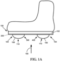
- At least one coordinate system (the anterior coordinate system, posterior coordinate system, protuberance coordinate system) has parallel longitudinal alignment lines. In some embodiments, at least one coordinate system is arranged along a curve. In some embodiments, the outsole map comprises at least one coordinate system having a lateral side and a medial side with respect to the foot of a subject. In some embodiments, the coordinate system comprises a lateral side that is symmetrical to the medial side. In some embodiments, the coordinate system comprises a lateral side that is asymmetrical to the medial side. All references to the protuberance adjustment system, i.e., outsole map and/or protuberance coordinate system as used herein relate to the gait/posture corrective shoe as viewed in a direction indicated in Fig. 1A by an arrow 150.
- the protuberance comprises a protuberance pivot, which provides a rotation axis for the protuberance.
- the protuberance coordinate system comprises alignment lines, which are brought into alignment with the outsole map during adjustment of the protuberance.
- the protuberance coordinate system comprises an anterior portion configured to align the anterior outsole map with a protuberance.
- the protuberance coordinate system comprises a posterior portion configured to align the posterior outsole map with a protuberance.
- an anterior coordinate system on the anterior outsole map having at least one (Wa) axis.
- the anterior coordinate system comprises a (Ma) axis.
- the anterior coordinate system comprises a set of longitudinal lines with which the protuberance pointers are aligned during adjustment of the protuberance.
- the set of anterior longitudinal lines have a central line, and in some embodiments, the central line is collinear with one of the axes of the anterior coordinate system.
- the anterior coordinate system comprises anterior longitudinal lines on the medial side of the central line.
- the anterior coordinate system comprises anterior longitudinal lines on the lateral side of the central line.
- the outsole comprises an anterior rail.
- the anterior rail midline is collinear with one of the axes of the anterior coordinate system.
- the protuberance is adjusted in respect to the axes of the anterior coordinate system.
- the posterior coordinate system comprises longitudinal lines.
- the longitudinal lines comprise hatch lines.
- the hatch lines provide a scale by which the protuberance is adjusted onto the posterior portion of the outsole.
- the outsole comprises a posterior rail.
- the posterior rail midline is an axis of the posterior coordinate system. in some embodiments, the posterior protuberance is adjusted in respect to the axes of the posterior coordinate system.
- the method comprises starting at the protuberance neutral position, aligning the protuberance center with the origin of the outsole anterior coordinate system. in some embodiments, the method comprises sliding the protuberance along the anterior rail center line. In some embodiments, the method comprises aligning a protuberance pointer with one of the longitudinal lines of the anterior coordinate system.
- the method comprises starting at the protuberance neutral position, aligning the protuberance center with the origin of the outsole anterior coordinate system such that the protuberance pivot is located on the lateral side with respect to the protuberance center.
- the method comprises rotating the protuberance over the protuberance pivot in the posterior directions.
- the method comprises aligning a protuberance pointer with one of the longitudinal lines of the anterior coordinate system.
- the method comprises starting at the protuberance neutral position, aligning the protuberance center with the origin of the outsole anterior coordinate system such that the protuberance pivot is located on the medial side with respect to the protuberance center.
- the method comprises rotating the protuberance over the protuberance pivot in the anterior.
- the method comprises aligning a protuberance pointer with one of the longitudinal lines of the anterior coordinate system.
- the method comprises starting at the protuberance neutral position, aligning the protuberance center with the origin of the outsole anterior coordinate system. in some embodiments, the method comprises rotating the protuberance over the protuberance pivot in one of the posterior or the anterior directions. In some embodiments, the method comprises sliding the protuberance along the anterior rail center line. In some embodiments, the method comprises aligning a protuberance pointer with one of the longitudinal lines of the anterior coordinate system.
- a method for anterior, posterior shift, lateral and medial shifting of the posterior protuberance comprises starting with the posterior protuberance in the neutral position, where the midline pointers are aligned with one of the posterior rail midline or the ML center line.
- the method comprises rotating the posterior protuberance about the protuberance pivot.
- the method comprises aligning the midline pointers with one of the longitudinal lines of the posterior coordinate system of the posterior outsole map.
- the method comprises starting with the posterior protuberance in the neutral position, where the midline pointers are aligned with one of the posterior rail midline or the ML center line.
- the method comprises sliding the protuberance along the posterior rail center line.
- the method comprises aligning the midline pointers with at least one of the longitudinal lines of the posterior coordinate system of the posterior outsole map.
- the present invention there is provided a method for a combined anterior or posterior shift and medial/lateral shift of the posterior protuberance.
- the method comprises starting with the posterior protuberance in the neutral position, where the midline pointers are aligned with one of the posterior rail midline or the ML center line.
- the method comprises rotating the posterior protuberance about the protuberance pivot.
- the method comprises sliding the protuberance along the posterior rail center line.
- the method comprises aligning the midline pointers with one of the longitudinal lines of the posterior coordinate system.
- a gait/posture corrective shoe which includes two bulbous protrusions protruding from the underside of footwear. One of the protuberances is positioned more posteriorly than the other protuberance. These bulbous protrusions are also referred to as protuberances.
- a gait/posture corrective shoe protuberance adjustment system In some embodiments, the protuberance adjustment system for footwear for footwear comprises an outsole having an anterior outsole map and a posterior outsole map. In some embodiments, the protuberance adjustment system for footwear comprises an outsole map.
- the protuberance adjustment system for footwear comprises an outsolemountable protuberance having at least one protuberance coordinate system corresponding to the outsole map.
- the alignment of the protuberance coordinate system with the outsole map places the protuberance in a predetermined position and/or orientation of the protuberance in respect to the outsole.
- each discrete alignment of the protuberance coordinate system with the outsole map corresponds to a discrete position of the protuberance in relation to the outsole.
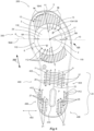
- Fig. 1A shows a side view simplified illustration of a corrective shoe, that is not an aspect of the present invention and thus provided for illustration purposes only.
- the corrective shoe comprises a protuberance for the footwear according to the present invention.
- the protuberance adjustment system 700 for footwear 100 comprises an outsole 102. In some embodiments, the protuberance adjustment system 700 for footwear comprises at least one protuberance 104. In some embodiments, one protuberance 104 is positioned more posteriorly than the other protuberance and is referred to as the posterior protuberance 106. In some embodiments, one protuberance 104 is positioned more anteriorly than the other protuberance and is referred to as the anterior protuberance 108. In some embodiments, the anterior protuberance 108 and the posterior protuberance 106 comprise the same markings. In some embodiments, the anterior protuberance 108 and the posterior protuberance 106 are interchangeable.
- the protuberance 104 comprises a protuberance coordinate system 110.
- the outsole comprises an outsole map 200. In some embodiments the protuberance 104 is a dome.
- the outsole map 200 comprises one or more separate portions, for example, one or more of an anterior outsole map 300 and a posterior outsole map 400.
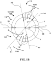
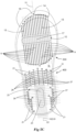
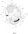
- Figs. 1B and 1C are plan view simplified illustrations of protuberance for the footwear in accordance with some embodiments of the invention.
- the protuberances 104/500 depicted by Figs. 1B and 1C are interchangeable within a protuberance adjustment system 700.
- the protuberance 104/500 comprises a protuberance center 1.
- the protuberance center 1 is marked on the protuberance.
- the protuberance center 1 is the concentric vertex of the protuberance 104/500.
- the protuberance center 1 comprises a concentric point of at least a portion of a circumference of the protuberance 104/500.
- the protuberance 104/500 comprises a protuberance pivot 2.
- the protuberance pivot 2 provides a rotation axis for the protuberance 104/500.
- the protuberance pivot 2 provides a rotation axis perpendicular to one or more of a diameter of the protuberance 104/500 and the outsole 102.
- the pivot point 2 is configured such that the angle between the rotation axis and the outsole 102 is 0-180 degrees.
- the protuberance pivot 2 is located 3-28mm from the protuberance center 1.
- the protuberance pivot 2 comprises a mechanical engagement element.
- the mechanical engagement element is one or more of a screw, a pin, and a clamp.
- the protuberance pivot 2 is a screw.
- the protuberance pivot 2 is a screw engagement pivot.
- the protuberance pivot 2 is a screw engagement pivot and is an integral part of the outsole 102.
- the protuberance 104/500 comprises one or more pointers 112.
- the one or more pointers 112 are marked coordinates along the circumference of the protuberance 104/500.
- pointers 112 are paired and arranged along a perimeter of protuberance 104/500.
- one or more alignment lines 3 are colinear with each pair of pointers 112.
- pointers are paired and diametrically opposed.
- the protuberance 104 comprises 4-6 pair of pointers 112.
- the alignment line 3 crosses the protuberance 104 diameter. In some embodiments, the alignment line 3 crosses the protuberance 104 diameter through the protuberance center 1. In some embodiments, the difference of the distances between each of the collinear pointers 112 of at least one pair of collinear pointers 112 and the protuberance pivot 2 is 0-10cm. In some embodiments, the difference of the distances between each of the collinear pointers 112 of at least one pair of collinear pointers 112 and the protuberance center 1 is 0-10cm.
- each pair of pointers 112 is marked on the protuberance 104. In some embodiments, there are 4-8 pairs of pointers 112. In some embodiments, the pointers 112 are used to align the protuberance 104 with the outsole map 200. In some embodiments, only one pointer 112 is used to align the outsole map 200. In some embodiments, only one pointer 112 is used to align the protuberance 104/105 with the outsole map 200. In some embodiments, the alignment of one pointer 112 with the outsole map 200 misaligns the remaining pointers 112 with the outsole map 200. In some embodiments, the pointers 112 are numbered.
- the pointers 112 are divided to a plurality of sets 112.
- the protuberance 104 comprises two sets of pointers 114A and 114B, and the sets of pointers, 114A and 114B, are symmetrical across a diameter of the protuberance.
- the protuberance 500 comprises four sets of pointers.
- each alignment line 3 is collinear with two pointers 112 marked by the same mark. For example, alignment line 3-0 of fig.
- alignment line 3 shows an alignment line 3 having two pointers 112 each labeled No. 0.
- alignment line 3-4 shows an alignment line 3 having two pointers 112 each labeled No. 4.
- each one of the two pointers 112 of an alignment line 3 is in a different set of pointers 114A and 114B.
- the alignment lines 3 are numbered at either or both pointers 112 of the alignment line 3.
- the protuberance 104/500 comprises midline pointer 6.
- the protuberance 104 comprises at least one midline pointer 6, for example, a first midline pointer 6A and a second midline pointer 6B.
- the distance between the first midline pointer 6A and the protuberance pivot 2 is larger than the distance between the second midline pointer 6B and the protuberance pivot 2.
- the first and second midline pointers 6A and 6B are collinear.
- the virtual collinear line of the midline pointers 6 crosses the protuberance 104/500 diameter.
- the virtual collinear line of the midline pointer 6 crosses the protuberance 104/500 diameter through the protuberance center 1.
- the midline pointer 6 splits the protuberance 104/500 symmetrically.
- the pointers 112 are numbered starting with No. 0.
- the midline pointer 6 is numbered.
- the midline pointers 6 comprise pointers 112 that are marked with the No. 5.
- the midline pointers 6 comprise pointers 112 which are marked with the No. 5A and 5B.
- the protuberance comprises an anterior section 116 and a posterior section 118.
- each portion comprises a set of alignment lines 3.
- the anterior section 116 is marked.
- the anterior section 116 is marked with the letter A 8.
- the posterior section 118 is marked.
- the posterior section 118 is marked with the letter P 7.
- the collinear line of the midline pointer 6 comprises pointers 112 that separates between the anterior section 116 and the posterior section 118.
- a potential advantage of the protuberance coordinate system 110 is in that it enables alignment of the protuberance 104/500 with the outsole 102. This alignment allows a user to control the position of the protuberance 104/500 in relation to the outsole 102.
- a potential advantage of the protuberance coordinate system 110 comprising a posterior section 118 and an anterior section 116 is that the protuberance coordinate system is used to control the positioning of a protuberance 104 that is placed on an outsole 102, and therefore the protuberance 104 is independent of the outsole 102.
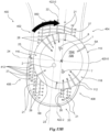
- the protuberance 500 comprises a plurality sets of pointers, such as, for example, the four sets 502, 504, 506, and 508, as depicted in Fig. 1C .
- the protuberance 500 comprises a midline 600 which is colinear with the first midline pointer 6A, the second midline pointer 6B, and the protuberance center 1.
- each set of pointers 502/504/506/508 comprises a plurality of pointers 112.
- the midline 600 divides the protuberance 500 into two halves.
- one or more additional lines 660 traverse the midline 600 such that each of the halves are split into two or more sections.
- each of the sections comprise a set of pointers, such as the sets 502/504/506/508.
- the one or more additional lines 660 are colinear with one or more pairs of pointers 112, for example, in the embodiment depicted by Fig. 1C , the additional line 660 is colinear with the pair of pointers 112 marked by the No. 0.
- the sets of pointers 502/504/506/508 comprise one or more pointers which are configured to align with the outsole map 200.
- two or more of the sets 502/504/506/508 are symmetrical in relation to one or more of the midline 600 and the additional line 660.
- one or more of the sets 502/504/506/508 are configured for alignment of the protuberance 500 with different portions of the anterior outsole map 300.
- one or more of the sets 502/504/506/508 are configured for alignment of the protuberance 500 with a portion of the outsole map 300 anterior in relation to an anterior rail midline.
- one or more of the sets 502/504/506/508 are configured for alignment of the protuberance 500 with a portion of the outsole map 300 posterior in relation to the anterior rail midline.
- the one or more sets 502/504/506/508 which are configured to align with the portion of the anterior outsole map.
- alignment of the protuberance 500 places the protuberance center 1 either posterior or anterior to an anterior rail midline of the outsole 102.
- one or more sets 502/504/506/508 are marked P and are configured to align with the outsole map 200 such that the protuberance center 1 is positioned in a portion of the outsole map 200 which is posterior in relation to the anterior rail midline.
- one or more sets 502/504/506/508 are marked A and are configured to align with the outsole map 200 such that the protuberance center 1 is positioned in a portion of the outsole map 200 which is anterior in relation to the anterior rail midline.
- the sets of pointers 502/504/506/508 are positioned along the protuberance such that the pointers 112 of the protuberance 500 are symmetrically positioned.
- a plurality of the pointers 112 comprise a plurality of symmetry lines.
- a potential advantage of the protuberance 500 comprising a plurality of pointers 112 which are positioned symmetrically in relation to a plurality of symmetry lines is in that the protuberance 500 is alignable with one or more of the medial and lateral sides of the outsole 102 regardless of the position of the center 1 and/or the pivot 2 in relation to the anterior rail midline.
- the outsole map 200 comprises at least one or more of an anterior outsole map 300 and a posterior outsole map 400.
- the outsole map 200 comprises a plurality of coordinate systems.
- the anterior outsole map 300 is different than the posterior outsole map 400.
- the outsole map 200 comprises an anterior coordinate system 120.
- the coordinate system 120 comprises at least one of a (Ma) axis 12-0 and a (Wa) axis 19-0.
- the anterior coordinate system 120 comprises anterior longitudinal lines 9. In some embodiments, the anterior longitudinal lines 9 are parallel. In some embodiments, the anterior longitudinal lines 9 are marked in the anterior-posterior direction 202. In some embodiments, one of the anterior longitudinal lines 9 is an anterior central line 11. In some embodiments, the anterior central line 11 is marked 0. In some embodiments, the anterior central line 11 is in the center of the anterior longitudinal line 9. In some embodiments, the anterior longitudinal lines 9 comprise one or more of medial-anterior longitudinal lines 14 and lateral-anterior longitudinal lines 16.
- the anterior central line 11 splits the anterior outsole map 300 to the outsole medial segment 13 and the outsole lateral segment 15.
- the outsole medial segment 13 comprises a portion of the longitudinal lines 9, for example, the medial-anterior longitudinal lines 14.
- the outsole lateral segment 15 comprises a portion of the longitudinal lines 9, for example, the lateral-anterior longitudinal lines 16.
- the outsole medial segment 13 is the portion of the outsole from the anterior central line 11 to the medial side of the outsole.
- the outsole medial segment comprises anterior medial longitudinal lines 14.
- the medial-anterior longitudinal lines 14 are the anterior longitudinal lines 9 on the outsole medial segment 13.
- the medial-anterior medial longitudinal lines 14 are marked in ascending and/or descending order.
- the medial-anterior longitudinal lines 14 are marked by a letter proceeded with a number, e.g., M1, M2, M3.
- the outsole lateral segment 15 is the portion of the outsole from the anterior central line 11 to the lateral side of the outsole.
- the outsole medial segment comprises anterior-lateral longitudinal lines 16.
- the lateral-anterior longitudinal lines 16 are the anterior longitudinal lines 9 on the outsole medial segment 13.
- the lateral-anterior longitudinal lines 16 are marked in ascending order.
- the lateral-anterior longitudinal lines 16 are marked by a letter proceeded with a number, e.g., L1, L2, L3.
- the distance between two consecutive anterior longitudinal lines 9 is 0.05-15mm. In some embodiments, the distance between two consecutive anterior longitudinal lines 9 is 5-10mm. In some embodiments, the distance between two consecutive the anterior longitudinal lines 9 varies. In some embodiments, the distances between two consecutive anterior longitudinal lines 9 is different for different sized outsoles. In some embodiments, the distance between two consecutive anterior longitudinal lines 9 is proportional to the outsole length. In some embodiments, the distance between two consecutive anterior longitudinal lines 9 is proportional to the outsole width.
- the anterior outsole map 300 comprises at least one anterior rail 204, configured to accommodate a protuberance 104.
- the anterior outsole map 300 comprises an anterior rail 204, configured to accommodate a coupling e.g., a screw, pin, gear.
- the coupling couples the protuberance 104 and the outsole 102.
- the anterior outsole map 300 is positioned in relation to the anterior rail 204.
- the anterior rail 204 comprises an anterior rail midline 10, which comprises a virtual line along the longitudinal axis of the anterior rail 204.
- the anterior rail midline 10 splits the anterior rail 204 into two segments.
- the anterior rail midline 10 splits the anterior rail 204 to two segments in the anterior-posterior direction 202.
- the anterior rail midline 10 and the anterior central line 11 of the anterior longitudinal lines 9 form an angle of 0 to 180 degrees.
- the angle between the anterior rail midline 10 and the anterior central line 11 is 90.
- the anterior rail midline 10 and the anterior central line 11 of the anterior longitudinal lines 9 form an angle of 45-125 degrees.
- the angle between the anterior rail midline 10 and the anterior central line 11 of the anterior longitudinal lines 9 is 60-90 degrees.
- the angle between the anterior rail midline 10 and the anterior central line 11 of the anterior longitudinal lines 9 is different for different sized outsoles.
- the angle between the anterior rail midline 10 and the anterior central line 11 of the anterior longitudinal lines 9 is proportional to the length of the outsole. In some embodiments, the angle between the anterior rail midline 10 and the anterior central line 11 of the anterior longitudinal lines 9 is proportional to the width of the outsole.
- the coordinate system 120 comprises a (Wa) axis 19-0. In some embodiments, the coordinate system 120 comprises a (Ma) axis 12-0.
- One of the axes of the anterior coordinate system 120 is collinear with the anterior rail midline 10. In some embodiments, one of the axes of the anterior coordinate system 120 is collinear with the anterior central line 11 of the anterior longitudinal lines 9. In some embodiments, the axes of the anterior coordinate system 120 are perpendicular. In some embodiments, the axes of the anterior coordinate system 120 form an angle of 10-90 degrees.
- the cross section of the anterior rail midline 10 and the anterior central line 11 of the anterior longitudinal lines 9 is the midpoint of the rail midline 10. In some embodiments, the cross section of the anterior rail midline 10 and the anterior central line 11 of the anterior longitudinal lines 9 comprises an anterior origin 17 of the anterior coordinate system 120.
- the anterior outsole map 300 comprises at least one virtual matrix 18.
- the virtual matrix 18 comprises matrix latitudinal lines 19.
- the matrix latitudinal lines 19 are parallel to the anterior rail midline 10.
- the angle between the matrix latitudinal lines 19 and the anterior rail midline 10 is 0.01-180 degrees.
- the angle between the matrix latitudinal lines 19 and the anterior rail midline 10 is 10-100 degrees.
- the angle between the matrix latitudinal lines 19 and the anterior rail midline 10 is 20-45 degrees.
- the matrix latitudinal lines 19 are curved. In some embodiments, the matrix latitudinal lines 19 are equally spaced from each other. In some embodiments, one axis of the virtual matrix 18 is the anterior rail midline 10. In some embodiments, the matrix latitudinal lines 19 are on both anterior and posterior sides of the rail. In some embodiments, the virtual matrix 18 comprises one or more matrix longitudinal lines 9. In some embodiments, the matrix longitudinal lines 9 comprise and/or are parallel to one or more of the lateral-anterior longitudinal lines 16 and the medial-anterior longitudinal lines 14.
- the posterior outsole map 400 comprises posterior longitudinal lines 21.
- the posterior longitudinal line 21 are anterior to the posterior rail 410.
- the posterior longitudinal lines 21 are posterior to the posterior rail 410.
- the posterior longitudinal lines 21 are placed medially in relation to the posterior rail 410.
- the posterior longitudinal lines 21 are placed laterally in relation to the posterior rail 410.
- the posterior longitudinal lines 21 are parallel.
- the posterior longitudinal lines 21 are equally spaced apart. In some embodiments, the distance between the posterior longitudinal lines 21 varies. In some embodiments, different posterior longitudinal lines 21 are marked on different areas of the posterior portion of the outsole. In some embodiments, the distance between the posterior longitudinal lines 21 is between 0.05-15 mm. In some embodiments, the distance between the posterior longitudinal lines 21 is between 3-10 mm. In some embodiments, the distance between the posterior longitudinal lines 21 is different in different sized outsoles. In some embodiments, the distance between the posterior longitudinal lines 21 is proportional to the length of the outsole. In some embodiments, the distance between the posterior longitudinal lines 21 is proportional to the width of the outsole.
- the posterior longitudinal lines 21 are in the anterior-posterior direction 202. In some embodiments, the angle between the posterior longitudinal lines 21 of the outsole and the anterior longitudinal lines 9 is between 0-180 degrees. In some embodiments, the angle between the posterior longitudinal lines 21 and the anterior longitudinal lines 9 is between 45-125 degrees. In some embodiments, the angle between the posterior longitudinal lines 21 the anterior longitudinal lines 9 is between 60-100 degrees. In some embodiments, the angle between the posterior longitudinal lines 21 and the anterior longitudinal lines 9 is different in different sized outsoles 102. In some embodiments, the angle between the posterior longitudinal lines 21 and the anterior longitudinal lines 9 is proportional to the length of the outsole 102. In some embodiments, the angle between the posterior longitudinal lines 21 and the anterior longitudinal lines 9 is proportional to the width of the outsole 102.
- the posterior longitudinal lines 21 comprise a ML center line 22.
- the ML center line 22 is parallel to the posterior longitudinal lines 21.
- the ML center line 22 is marked on the outsole 102.
- the ML center line 22 is the middle line of the posterior longitudinal lines 21.
- the posterior outsole map 400 comprises at least one posterior rail 410, configured to accommodate a protuberance.
- the posterior outsole map 400 comprises a posterior rail 410, configured to accommodate a coupling e.g., a screw, pin, gear.
- the coupling couples the protuberance 104 and the outsole 102.
- the posterior rail 410 comprises a posterior rail midline 23.
- the posterior rail midline 23 is a virtual line.
- the posterior rail midline 23 splits the posterior rail 410 into two segments.
- the posterior rail midline 23 splits the posterior rail 410 into two symmetric segments.
- the posterior rail midline 23 splits the posterior rail 410 into two segments in the medial-lateral direction 450.
- the posterior rail midline 23 and the ML center line 22 are collinear.
- the posterior rail midline 23 and the ML center line 22 are parallel.
- the angle between the posterior rail midline 23 and the ML center line 22 is between 0-180 degrees.
- the angle between the posterior midline 23 and the ML center line 22 is different in different sized outsoles 102.
- the angle between the posterior rail midline 23 and the ML center line 22 is proportional to the length of the outsole 102.
- the angle between posterior rail midline 23 and the ML center line 22 is proportional to the width of the outsole 102.
- the posterior outsole map 400 comprises an AP center line 24.
- the AP center line 24 is a virtual line.
- the AP center line 24 is perpendicular to the posterior rail midline 23.
- the angle between the AP center line 24 and the posterior rail midline 23 is between 0-180 degrees.
- the angle between the AP center line 24 and the posterior rail midline 23 is different in different sized outsoles 102.
- the angle between the AP center line 24 and the posterior rail midline 23 is proportional to the length of the outsole 102.
- the angle between the AP center line 24 and the posterior rail midline 23 is proportional to the width of the outsole 102.
- the posterior outsole map 400 comprises at least one posterior coordinate system 20.
- the posterior coordinate system 20 comprises at least one (Mp) axis 422.
- the posterior coordinate system comprises a (Wp) axis 420-0.
- at least one of the axes of the posterior coordinate system 20 is collinear with the ML center line 22.
- One of the axes of the posterior coordinate system 20 is collinear with the posterior rail midline 23.
- at least one of the axes of the posterior coordinate system 20 is collinear with the AP center line 24.
- at least one of the axes of the posterior coordinate system 20 is perpendicular to the AP center line 24.
- the axes of the posterior coordinate system 20 are perpendicular.
- the posterior origin 25 is the cross section of the (Mp) axis 422 and (Wp) axis 420-0 of the posterior coordinate system 20.
- the posterior coordinate system 20 divides the posterior outsole map to at least four quadrants: medial-anterior quadrant 402, medial-posterior quadrant 406, lateral-anterior quadrant 404, and lateral-posterior quadrant 408.
- the medial-anterior quadrant 402 is symmetrical to the medial-posterior quadrant 406 in relation to the (Wp) axis 420-0. In some embodiments, the medial-anterior quadrant 402 is asymmetrical to the medial-posterior quadrant 406 in relation to the (Wp) axis 420-0. In some embodiments, the lateral-anterior quadrant 404 is symmetrical to the lateral-posterior quadrant 408 in relation to the (Wp) axis 420-0. In some embodiments, the lateral-anterior quadrant 404 is asymmetrical to the lateral-posterior quadrant 408 in relation to the (Wp) axis 420-0. In some embodiments, the medial-anterior quadrant 402 is symmetrical to the lateral-anterior quadrant 404 in relation to the (Mp) axis 422.
- the medial-anterior quadrant 402 is asymmetrical to the lateral-anterior quadrant 404 in relation to the (Mp) axis 422. In some embodiments, the medial-posterior quadrant 406 is symmetrical to the lateral-posterior quadrant 408 in relation to the (Mp) axis 422. In some embodiments, the medial-posterior quadrant 406 is asymmetrical to the lateral-posterior quadrant 408 in relation to the (Mp) axis 422. In some embodiments, at least one of the lateral-anterior quadrant 404, the medial-anterior quadrant 402, the lateral-posterior quadrant 408, and/or the medial-posterior quadrant 406, comprise no markings.
- the posterior longitudinal lines 21 comprise medially shifting lines 26 and laterally shifting lines 27.
- the medially shifting lines 26 are marked on the outsole 102 in ascending order.
- the medially shifting lines 26 are marked on the outsole 102 by the letter M proceeded with a number, e.g., M1, M2, M3.
- the medially shifting lines 26 comprise of 1-15 lines.
- at least one of the medially shifting lines 26 is marked on the medial-anterior quadrant 402.
- at least one of the medially shifting lines 26 is marked on the lateral-posterior quadrant 408.
- the laterally shifting lines 27 are marked on the outsole 102 in ascending order. In some embodiments, the laterally shifting lines 27 are marked on the outsole 102 by the letter L proceeded with a number, e.g., L1, L2, L3. In some embodiments, the laterally shifting lines 27 comprise of 1-15 lines. In some embodiments, at least one of the laterally shifting lines 27 is marked on the lateral-anterior quadrant 404. In some embodiments, at least one of the laterally shifting lines 27 is marked on the medial-posterior quadrant 406.
- the medial-posterior quadrant 406 comprises medially shifting lines 26 that are mirroring the laterally shifting lines of the lateral-posterior quadrant 408.
- the medial-anterior quadrant 402 comprises medially shifting lines 26 that are mirroring the laterally shifting lines 27 of the lateral-anterior quadrant 404.
- the laterally shifting lines 27 form a mirror view of the medially shifting lines 26.
- the posterior longitudinal lines 21 comprise hatch marks 28. In some embodiments, the hatch marks 28 are equally distanced. In some embodiments, the hatch marks 28 are comprised of 1-20 marks. In some embodiments, the hatch marks 28 comprise of 3-7 marks. In some embodiments, the hatch marks are perpendicular to the posterior longitudinal lines 21. In some embodiments, the angle between a hatch mark 28 and the posterior longitudinal lines 21 is between 0-180 degrees. In some embodiments, the angle between each hatch mark 28 on a single line of the posterior longitudinal lines 21 is different. In some embodiments, the hatch marks 28 are arched. In some embodiments, the hatch marks 28 are arranged along a curve.
- the hatch marks 28 are arranged along a curve having a radius equal to the radius of the posterior protuberance 106. In some embodiments, the hatch marks 28 are arranged symmetrically in relation to at least one of the posterior longitudinal lines 21. In some embodiments, the hatch marks 28 are arranged along a curve having a radius larger than the radius of the posterior protuberance 106. In some embodiments, the hatch marks 28 are marked with reference numbers. In some embodiments, the hatch marks 28 reference numbers correspond to the position of a protuberance 104. In some embodiments, the distance between the hatch marks 28 is proportional to the size of the outsole 102. In some embodiments, the distance between the hatch marks 28 is proportional to the length of the outsole 102. In some embodiments, the distance between the hatch marks 28 is proportional to the width of the outsole 102.
- the hatch marks 28 comprise a scale 412. In some embodiments, the scale 412 ranges from -10 to +7. In some embodiments, the scale 412 ranges from -6 to +2. In some embodiments, the scale 412 ranges from -5 to +1. In some embodiments, each of the longitudinal lines 21 comprises a different scale 412. In some embodiments, the scale 412 is marked on the outsole 102.
- the scale 412 correlates to the position of the protuberance center 1 in relation to the outsole 102. In some embodiments, the scale 412 correlates to the position of the protuberance pivot 2 in relation to the outsole 102. In some embodiments, the protuberance 104 is aligned with a hatch mark 28 labeled No. 0 in its neutral position, as described in greater detail elsewhere herein.
- the outsole map 200 comprises discrete coordinates. In some embodiments, each coordinate is unique, enabling only a single alignment position of the protuberance in respect to the outsole map.
- outsole map 200 comprises scattered coordinates 550. In some embodiments, the scattered points 550 are non-collinear. In some embodiments, the scattered coordinates 550 of an outsole 102 vary in location on the outsole map 200 according to the desired implementation of the adjustment system. In some embodiments, the coordinates are visually suggestive to an observer as having arbitrary distribution.
- At least one anterior protuberance 108 is connected to the outsole 102 via the anterior rail 204.
- at least one posterior protuberance 106 is connected to the outsole via the posterior rail 410.
- the anterior protuberance 108 comprises pointers 112.
- the posterior protuberance comprises pointers 112.
- the pointers 112 of the protuberances 104 are aligned with the outsole map 200.
- the protuberance 104 pointers 112 are aligned with the outsole map 200 by sliding the protuberance 104 along the posterior and/or anterior rail 410/204.
- the protuberance 104 pointers 112 are aligned with the outsole map 200 by rotating the protuberance 104.
- the outsole map is configured such that alignment of the protuberance with the outsole map includes a series of one or more alignments of the pointer 112 with the outsole map.
- the outsole map comprises longitudinal lines without hatch marks or scales.
- positioning of the protuberance comprises rotating the protuberance to align one of the pointers 112 with one of the longitudinal lines, and then sliding the protuberance along the rail such that one of the pointers 112 is aligned with another one of the longitudinal lines.
- the outsole map comprises one or more marked coordinates such that positioning of the protuberance in relation to the outsole includes alignments of one of the pointer 112 with one of the marked coordinates.
- each protuberance 104 position enables a monovalent positioning in respect to the outsole map 200.
- monovalent coding refers to a distinct position of the protuberance 104.
- the anterior protuberance 108 is set to a neutral position.
- the anterior protuberance 108 is shifted in the lateral direction of the outsole.
- the anterior protuberance 108 is shifted in the medial direction of the outsole.
- the anterior protuberance 108 is shifted in the anterior direction of the outsole.
- the anterior protuberance 108 is shifted in the posterior direction of the outsole.
- the anterior protuberance 108 is shifted by sliding the anterior protuberance 108 along the anterior rail 204.
- the anterior protuberance 108 is shifted by rotating the anterior protuberance 108 about the protuberance pivot 2.
- Fig. 6 is a plan view simplified illustration of an anterior protuberance in neutral position in accordance with some embodiments of the invention.
- the neutral position 29 of the anterior protuberance 108 comprises of the protuberance center 1, which coincides with an anterior origin 17 of the anterior coordinate system of the anterior outsole map 200.
- the neutral position 29 of the anterior protuberance 108 comprises of the alignment of one alignment line 3 with the (Ma) axis 12-0.
- the (Ma) axis 12-0 is collinear with the anterior central alignment line 11 and with the alignment line 3 marked as no. 0.
- Fig. 7A , 7B , and 7C are plan view simplified illustrations a neutral position proceeding an anterior shift of the anterior protuberance or a posterior shift of the anterior protuberance in accordance with some embodiments of the invention.
- the neutral position 29 of the protuberance proceeds an anterior shift of the anterior protuberance 108.
- the protuberance pivot 2 is located at the medial side of the outsole 102 with respect to the protuberance center 1.
- the anterior section 116 is positioned on the outsole 102 anteriorly in relation to the posterior section 118.
- the letter A 8 marked on the protuberance is directed anteriorly in respect to the letter P 7.
- the neutral position 29 of the protuberance proceeds a posterior shift of the anterior protuberance 108.
- the protuberance pivot 2 is located at the lateral side with respect to the protuberance center 1.
- the posterior section 118 is positioned on the outsole 102 anteriorly to the anterior section 116.
- the letter P 7 marked on the protuberance 104 is directed anteriorly in respect to the letter A8.
- the method comprises starting at the anterior protuberance neutral position 29 as explained in greater detail elsewhere herein.
- the method comprises aligning the protuberance center 1 with the anterior origin 17 of the anterior coordinate system such that the protuberance pivot 2 is located on the lateral side with respect to the protuberance center 1.
- the method comprises sliding the anterior protuberance 108 along the anterior rail 204 center line 10.
- the method comprises of aligning one pointer 112 with one of the anterior longitudinal lines 9.
- Fig. 8 is a plan view simplified illustration of a medial shift of the anterior protuberance in accordance with some embodiments of the invention.
- the protuberance center 1 shifts along the anterior rail midline 10.
- the protuberance center 1 has been shifted along the anterior rail 204 from the (Ma) axis 12-0, which in this embodiment is collinear with the anterior central line11, to an anterior longitudinal line 9 marked M3 12-3.
- the protuberance center 1 shift along the anterior rail midline 10 in the medial direction 850.
- the distance between two consecutive anterior longitudinal lines 9 is 0.5-10mm.
- shifting one pointer 112 from one anterior longitudinal line 9 to the next shifts the protuberance center 1 by 0.5-10mm along the anterior rail midline 10.
- the distance between two consecutive anterior longitudinal lines 9 is 5mm.
- a method for a posterior shift of the anterior protuberance 108 of the suggested footwear comprises starting at the anterior protuberance neutral position 29 as explained in further detailed elsewhere herein.
- the method comprises rotating the anterior protuberance over the protuberance pivot 2 in the posterior direction.
- the method comprises rotating the anterior protuberance over the protuberance pivot 2 in the posterior direction such that the protuberance center 1 shifts in the posterior direction.
- Fig. 9 is a plan view simplified illustration of a posterior shift of the anterior protuberance in accordance with some embodiments of the invention.
- the alignment of one pointer 112, for example the pointer 112 labeled No. 1, with the (Ma) axis 12-0 of the anterior coordinate system positions the protuberance center 1 on the (Ma) axis 12-0 1-5mm posteriorly with respect to the (Wa) axis 19-0.
- each pointer 112 with a longitudinal line 9 positions the protuberance center 1 on a latitudinal line 19.
- the rotation of the anterior protuberance aligns the pointer 112 labeled No. 2 with the anterior central line 11, which positions the protuberance center 1 at a latitudinal line 19-2.
- the distance between two consecutive matrix latitudinal lines 19 is 2mm.
- the positions of the protuberance center 1 on the (Ma) axis 12-0 are obtained by rotation of the anterior protuberance 108. In some embodiments, the positions of the protuberance center 1 on the (Ma) axis 12-0 are obtained by aligning at least one of the pointers 112 with the anterior longitudinal lines 9. In some embodiments, each of the pointers 112 corresponds to a specific distance of the protuberance center 1 from the (Wa) axis 19-0. In some embodiments, the distance of the protuberance center 1 from the (Wa) axis 19-0 increases with the increase of the number of the pointer 112.
- the distance of the protuberance center 1 from the (Wa) axis 19-0 decreases with the increase of the number of the pointer 112. In some embodiments, the difference in distance of the protuberance center 1 from the (Wa) axis 19-0 created by rotating the protuberance 104 from one pointer 112 to the proceeding pointer 112 is 1-10 mm.
- the difference in distance of the protuberance center 1 from the (Wa) axis 19-0 created by rotating the anterior protuberance 108 from one pointer 112 to the proceeding pointer 112 is constant. In some embodiments, the difference in distance of the protuberance center 1 from the (Wa) axis 19-0 created by rotating the anterior protuberance 108 from one alignment line 3 to the proceeding alignment line 3 varies. In some embodiments, the difference in distance of the protuberance center 1 from the (Wa) axis 19-0 created by rotating the anterior protuberance 108 from one pointer 112 to the proceeding pointer 112 increases when the rotation in counter-clockwise direction such as depicted by arrow 950.
- a method for an anterior shift of the anterior protuberance 108 of the suggested footwear comprises starting at the protuberance neutral position 29 as explained in greater detail elsewhere herein.
- the method comprises rotating the anterior protuberance 108 over the protuberance pivot 2 in the anterior direction.
- the method comprises rotating the anterior protuberance 108 over the protuberance pivot 2 in the anterior direction such that the protuberance center 1 shift in the anterior direction.
- Fig. 10 is a plan view simplified illustration of an anterior shift of the anterior protuberance in accordance with some embodiments of the invention.
- the alignment of pointers 112, e.g., the pointer 112 labeled No. 1, with the (Ma) axis 12-0 of the anterior coordinate system positions the protuberance center 1 on the (Ma) axis 12-0 1-5mm anteriorly with respect to the (Wa) axis.
- the alignment of one pointer 112, e.g., the pointer 112 labeled No. 2 with the (Ma) axis 12-0 of the anterior coordinate system positions the protuberance center 1 1-5mm anteriorly on the (Ma) axis 12-0 with respect to the (Wa) axis.
- the alignment of each proceeding pointer 112 with the (Ma) axis 12-0 positions the protuberance center 1 on the (Ma) axis 12-0 at least 1-5 mm anterior to the preceding pointer 112.
- the rotation of the anterior protuberance aligns the pointer 112 labeled No. 2 with the anterior central line 11, which positions the protuberance center 1 on a latitudinal line 19-4.
- the distance between two consecutive matrix latitudinal lines 19 is 2mm.
- the positions of the protuberance center 1 on the (Ma) axis 12-0 are obtained by rotation of the anterior protuberance 108. In some embodiments, the positions of the protuberance center 1 on the (Ma) axis 12-0 are obtained by aligning the alignment lines 3 with the anterior longitudinal lines 9. In some embodiments, each alignment of a pointer 112 with an anterior longitudinal line 9 corresponds to a specific distance of the protuberance center 1 from the (Wa) axis 19-0. In some embodiments, the alignment of a pointer 112, for example, the pointer 112 labeled No. 3, with one anterior longitudinal line 9, distances the protuberance center 1 from the (Wa) axis 19-0.
- the difference in distance of the protuberance center 1 from the (Wa) axis 19-0 created by rotating the protuberance from one pointer 112 to the proceeding pointer 112 is 1-10 mm.
- the difference in distance of the protuberance center 1 from the (Wa) axis 19-0 created by rotating the protuberance from one pointer 112 to the proceeding pointer 112 is constant. In some embodiments, the difference in distance of the protuberance center 1 from the (Wa) axis 19-0 created by rotating the protuberance from one pointer 112 to the proceeding pointer 112 varies. In some embodiments, the difference in distance of the protuberance center 1 from the (Wa) axis 19-0 created by rotating the protuberance from one pointer 112 to the pointer 112 increases when the rotation in counter-clockwise direction such as depicted by arrow 950.
- a combined shift comprises of a posterior and a lateral shift.
- a combined shift comprises of an anterior and a lateral shift.
- a combined shift comprises of a posterior and a medial shift.
- a combined shift comprises of an anterior and a medial shift.
- the method comprises starting with the anterior protuberance 108 in the neutral position 29, such as described in greater detail elsewhere herein.
- the method comprises sliding the anterior protuberance 108 along the anterior rail 204.
- the method comprises rotating the anterior protuberance 108 about the protuberance pivot 2.
- the method comprises both sliding the anterior protuberance 108 along the anterior rail 204 and rotating the anterior protuberance 108 about the protuberance pivot 2.
- Fig. 11 is a plan view simplified illustration of a combined shift in accordance with some embodiments of the invention.
- the method comprises combined shifting and sliding until the protuberance pivot 2 is located in the desired position.
- the method comprises combined shifting and sliding until a chosen pointer 112 is aligned with a chosen anterior longitudinal line 9.
- the pointer labeled No. 4 is aligned with the anterior longitudinal line 9 marked L2, which positions the protuberance center 1 on the intersection of a longitudinal line 12-4 and a latitudinal line 19-5.
- Fig. 12 is a plan view simplified illustration of a posterior protuberance in neutral position in accordance with some embodiments of the invention.
- the neutral position is the initial protuberance position before adjustments are made to the position of the protuberance.
- the neutral position of the posterior protuberance 106 comprises the protuberance center 1, which coincides with the posterior origin 25 of the posterior coordinate system 20 of the posterior outsole map 400.
- the neutral position of the posterior protuberance 106 comprises of the alignment of the midline pointer 6 with one of the posterior rail midline 23 and/or the ML center line 22.
- the posterior protuberance 106 is positioned by alignment of the midline pointer 6 with the marks of the posterior coordinate system 20 of the posterior outsole map 400. In some embodiments, the protuberance 106 is aligned with a hatch mark 28. In some embodiments, the hatch mark 28 is marked with a scale 412. In some embodiments, the neutral position of the protuberance 106 comprises aligning the protuberance 106 with a hatch mark 28 labeled by the scale 412 as neutral, e.g. marked N, marked No. 0.
- Fig. 13 is a plan view simplified illustration of a lateral shift of the posterior protuberance.
- a method for lateral shifting of the posterior protuberance 106 comprises starting with the posterior protuberance 106 in the neutral position, such as described in greater detail elsewhere herein.
- the method comprises rotating the posterior protuberance 106 about the protuberance pivot 2.
- the method comprises placing at least one of the midline pointers 6 in the lateral-anterior quadrant 404 and the medial-posterior quadrant 408.
- the method comprises rotating the posterior protuberance 106 into a position where the first midline pointer 6A is in the lateral-anterior quadrant 404. In some embodiments, the method comprises rotating the protuberance into a position where the second midline pointer 6B is in the medial-posterior quadrant 406. In some embodiments, the method comprises rotating the posterior protuberance to align the midline pointers 6 with the posterior coordinate system 20. In some embodiments, the method comprises rotating the posterior protuberance 106 to align the midline pointers 6 with at least one laterally shifting line 27. In some embodiments, the method comprises rotating the posterior protuberance 106 to align the midline pointers 6 with at least one of the hatch marks 28 of a laterally shifting line 27. In some embodiments, the transition of a midline pointer 6 from one laterally shifting line 27 to the next results in a 1-5 mm transverse shift of the protuberance center 1 in the direction of movement.
- the shift of the posterior protuberance aligns the first midline pointer 6A marked No. 5 with the posterior longitudinal line 21 marked L1 and hatch mark 28 marked No. 0 (Zero), on the lateral-anterior quadrant 404, which positions the protuberance center 1 on a posterior longitudinal line 422-1.
- the embodiment depicted by Fig 13B shows that the shift of the posterior protuberance aligns the second midline pointer 6B marked No. 5 with the posterior longitudinal line 21 marked L4 and hatch mark 28 marked No. 0, on the medial-posterior quadrant 406, which positions the protuberance center 1 on a posterior longitudinal line 422-2.
- one or more of the anterior outsole map and the posterior outsole map comprise longitudinal lines that are unmarked, or in other words, do not have one or more hatch marks along the length of the longitudinal line.
- Fig. 14 is a plan view simplified illustration of a medial shift of the posterior protuberance.
- a method for medial shifting of the posterior protuberance comprises starting with the posterior protuberance in the neutral position, such as described in greater detail elsewhere herein.
- the method comprises rotating the posterior protuberance about the protuberance pivot 2. In some embodiments, the method comprises placing the midline pointers 6 in the medial-anterior quadrant and the lateral-posterior quadrant. In some embodiments, the method comprises placing the midline pointers 6 in the medial-anterior quadrant and the lateral-posterior quadrant. In some embodiments, the method comprises rotating the posterior protuberance into a position where the first midline pointer 6A is in the medial-anterior quadrant.
- the method comprises rotating the protuberance into a position where the first midline pointer 6A is in the medial-anterior quadrant 402. In some embodiments, the method comprises rotating the protuberance into a position where the second midline pointer 6B is in the lateral-posterior quadrant 408.
- the method comprises rotating the posterior protuberance to align the midline pointers 6 with the posterior coordinate system 20. In some embodiments, the method comprises rotating the posterior protuberance to align the midline pointers 6 with at least one medially shifting line 26. In some embodiments, the method comprises rotating the posterior protuberance to align the midline pointers 6 with at least one of the hatch marks 28 on a medially shifting line 26. In some embodiments, transition of a midline pointer 6 moving from one medially shifting line 26 to the next results in a 1-5 mm transverse shift of the protuberance center 1 in the direction of movement.
- the shift of the posterior protuberance aligns the first midline pointer 6A marked No. 5 with the posterior longitudinal line 21 marked M1 and hatch mark 28 marked No. 0, on the medial-anterior quadrant 402, which positions the protuberance center 1 on a posterior longitudinal line 422-3.
- the embodiment depicted by Fig 14B shows that the shift of the posterior protuberance aligns the second midline pointer 6B marked No. 5 with the posterior longitudinal line 21 marked M4 and hatch mark 28 marked No. 0, on the medial-posterior quadrant 408, which positions the protuberance center 1 on a posterior longitudinal line 422-4.
- Fig. 15 is a plan view simplified illustration of an anterior-posterior shift of the posterior protuberance in accordance with some embodiments of the invention.
- a method for anterior and posterior shifting of the posterior protuberance 106 comprises starting with the posterior protuberance 106 in the neutral position, such as described in greater detail elsewhere herein.
- the method comprises aligning the midline pointers 6 with the posterior rail midline 23.
- the posterior rail midline 23 comprises hatch marks 28.
- the method comprises aligning the midline pointers 6 with the hatch marks 28 of the ML center line 22.
- shifting the midline pointer 6 from one hatch mark 28 to the proceeding hatch mark 28 creates a 1-7 mm longitudinal shift of the protuberance center 1 in the selected direction.
- the shift of the posterior protuberance aligns the first midline pointer 6A marked No. 5 with the ML central line 22 and hatch mark 28 marked No. -2, which positions the protuberance center 1 on a posterior latitudinal line 420-1.
- a combined shift comprises of a posterior and a lateral shift.
- a combined shift comprises of an anterior and a lateral shift.
- a combined shift comprises of a posterior and a medial shift.
- a combined shift comprises of an anterior and a medial shift.
- the method comprises starting with the posterior protuberance 106 in the neutral position, such as described in greater detail elsewhere herein.
- the method comprises sliding the posterior protuberance 106 along the posterior rail 410.
- the method comprises rotating the posterior protuberance 106 about the protuberance pivot 2.
- the method comprises both sliding the posterior protuberance along the posterior rail and rotating the posterior protuberance about the protuberance pivot 2.
- the method comprises aligning one of the pointers 112 with one of the markings of the posterior outsole map 400.
- the method comprises aligning the midline pointer 6 pointer 112 with one of the markings of the posterior outsole map 400.
- the shift of the posterior protuberance aligns the second midline pointer 6B marked No. 5 with the posterior longitudinal line 21 marked M3 and hatch mark 28 marked No. -2, on the lateral-posterior quadrant 408, which positions the protuberance center 1 on the intersection of a longitudinal line 23e and a posterior latitudinal line 420-2.
- an alignment of a specific pointer 112 with a specific coordinate point of the outsole map 200 is configured to place the protuberance center 1 in a predetermined position in respect to the outsole 102.
- the predetermined position of the protuberance center 1 is located on the outsole 102.
- an alignment of a specific pointer 112 with a specific coordinate point of the outsole map 200 is determined by a position of the protuberance 104 along a rail. In some embodiments, the rail limits the range of movement of the protuberance pivot 2. In some embodiments, a specific pointer 112 is aligned with a specific coordinate point of the outsole map 200 by rotation of the protuberance 104 about the protuberance pivot 2.
- the position of the protuberance center 1 on the outsole 102 is determined by its distance from the protuberance pivot 2 and the size of the rail.
- the distance and the size of the rail are such that maintain the protuberance center 1 inside the outsole 102.
- the distance between the protuberance center 1 and the protuberance pivot is L. Therefore, the rotation of the protuberance 104 about the protuberance pivot 2 allows aligning the protuberance concentric point 1 with any one of a set of coordinate points of the outsole map 200 that are at a distance L from the protuberance pivot 2.
- a potential advantage of this configuration is in that it provides an extensive range of alignment positions of the protuberance center 1 in respect to the outsole map 200.
- the midline pointers 6A and 6B are configured to align with different portions of the outsole map 200.
- the first midline pointer 6A is configured to align with M3 to L3 and the second midline pointer 6B is configured to align with the lines M4, M5, L4 and L5 of the posterior outsole map 400.
- the position code comprises of a set monovalent calibration positions for a protuberance 104.
- the position code comprises of a set monovalent calibration positions for an anterior protuberance 108.
- the position code comprises of a set monovalent calibration positions for a posterior protuberance 106.
- the position code comprises a set of monovalent calibration positions for the right and/or left foot.
- the position code comprises positions of the protuberance 104 on the outsole map 200.
- the position code corresponds between the position of the protuberance on the outsole and an orthopedic treatment.
- the position code defines the protuberance location. In some embodiments, the protuberance location code defines the location of at least one of the anterior left (AL), anterior right (AR), posterior left (PL), or posterior right (PR) protuberance. In some embodiments, the position code defines the protuberance diameter. In some embodiments, the protuberance diameter is or more of 85mm, 90mm, 95mm. In some embodiments, the position code defines the protuberance profile. In some embodiments, the protuberance profiles are labeled A, B, C, D. In some embodiments, the position code defines the protuberance hardness.
- the position code defines the protuberance center 1 position in relation to the anterior rail midline 10. In some embodiments, the position code defines the protuberance center 1 position in relation to at least one of the posterior rail midline 23 and the ML center line 22. In some embodiments, the position code defines which alignment line 3 pointer 112 is aligned with the outsole map 200. In some embodiments, the position code defines what part of the outsole map 200 the alignment line 3 pointer 112 is aligned with.
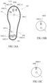
- Fig. 17C is a code line of position codes generated for a specific individual in accordance with some embodiments of the invention.
- a professional examines a subject and produces a position code configured to right a fault in a subject diagnosed by the professional.
- a protuberance position code is generated automatically, for example, by a gait diagnosis system including, for example, a treadmill, an imager and a computer to improve performance of a healthy subject, for example, in sports.
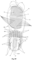
- Fig. 18A-C are plan view simplified illustrations of a protuberance adjustment system in accordance with some embodiments of the invention.
- the lock and key system 1808 couples the outsole 102 and the protuberance 104.
- the outsole 102 comprises an outsole component 1802 of the lock and key system 1808.
- the protuberance 104 comprises a protuberance component 1804 of the lock and key system 1808.
- the outsole component 1802 and the protuberance component 1804 are the lock and key system 1808.
- the lock and key system 1808 comprises a socket and a corresponding plug, e.g., a socket 1802-8 and plug 1804-2 or, alternatively and optionally, a socket 1804-2 and plug 1802-8.
- the lock and key system components are a pin and bore, e.g., pin 1804-2 and bore 1802-8 or, alternatively and optionally, pin 1802-8 and bore 1808-4.
- the protuberance component 1804 is positioned eccentrically on the protuberance 104. In some embodiments, the protuberance component 1804 is positioned concentrically with the protuberance 104. In some embodiments, a position of an outsole component 1802 is derived from a range of code lines, e.g., an averaged code line based on the range of code lines. Correspondingly, a position of a protuberance 104 lock and key component (e.g., lock and key component 1804-2) is derived from a range of code lines, e.g., an averaged code line based on the range of code lines.
- the code map is integrated into the predetermined position of the lock and key components 1802/1804 negating the need to mark the outsole map 200 and/or pointers 112 and/or alignment lines 3 on protuberance 104.
- a potential advantage of this configuration is in that a lock and key position is not patient specific and is suitable for several users or user types.
- the outsole component 1802 is positioned at a predetermined position of the outsole 102 in accordance with the code line and/or coding map 200.
- the outsole 102 comprises a plurality of outsole components 1802.
- the protuberance adjustment system comprises a plurality of protuberances 104 comprising distinct positions of the protuberance components 1804 in relation to the protuberance center 1 of the protuberance 104.
- the outsole components 1802 and the protuberance component 1804 are positioned to correspond to one or more positions in accordance with the position code ( Fig. 17 ). In some embodiments, the outsole components 1802 and the protuberance component 1804 are positioned to correspond to a range of positions in accordance with the position code. For example, in some embodiments one outsole component 1802 corresponds with the range of positions of protuberance 104 in which one pointer 112 of the protuberance 104 is aligned in accordance with a plurality of consecutive coordinates based on a generated outsole map 200. In some embodiments, an outsole component 1802 coupled to a protuberance component 1804 corresponds with a range of positions based on the positioning code.
- the protuberance 104/104-2/104-3 pointers 112 are invisible. In some embodiments, the outsole map 200 is invisible, or in other words, unmarked.
- the outsole 102 is universal and comprises a plurality of outsole components 1802 for positioning a protuberance 104 in a plurality of positions in accordance with the position code such that the outsole 102 is not patient specific.
- the protuberance 104 is universal.
- a universal protuberance 104 and a universal outsole 102 are coupled to produce a patient specific footwear.
- protuberance pivot 2 is coupled to one of the anterior rail 204-2 and the posterior rail 410-2.
- the anterior rail 204-2 and/or the posterior rail 410-2 is shaped to fix the protuberance 2 on the outsole 102.
- the anterior rail 204-2 is placed on one of the points of the anterior outsole map 300 coordinate system.
- the anterior rail 204-2 is centered at the anterior origin 17 of the anterior outsole map 300 coordinate system.
- the posterior rail 410-2 is placed on one of the points of the posterior outsole map 400 and based on coordinate system.
- the anterior rail 410-2 is centered at the posterior origin 25 based on the posterior outsole map 400.
- the outsole 102-2 comprises sockets 1802.
- the outsole 102-2 comprises a plurality of outsole components 1802 sockets.
- the protuberance 104 comprises a protuberance component 1804 plug configured to couple to one of the outsole components 1802 sockets.
- coupling the protuberance component 1804-2 is with any one of outsole components 1802 provides six distinct positions of the protuberance 104-2 onto outsole 102-2.
- coupling the protuberance component 1804-4 is with any one of outsole components 1802 provides six distinct positions of the protuberance 104-2 onto outsole 102-2.
- the combination coupling one of the protuberance components 1804-2/1804-4 with the outsole components 1802-2-1802-12 provides 24 distinct alignments of protuberances 104-2/104-3 on the outsole 102-2.
- each of the words “comprise” “include” and “have”, and forms thereof, are not necessarily limited to members in a list with which the words may be associated.
Landscapes
- Health & Medical Sciences (AREA)
- Epidemiology (AREA)
- General Health & Medical Sciences (AREA)
- Public Health (AREA)
- Pain & Pain Management (AREA)
- Physical Education & Sports Medicine (AREA)
- Rehabilitation Therapy (AREA)
- Life Sciences & Earth Sciences (AREA)
- Animal Behavior & Ethology (AREA)
- Veterinary Medicine (AREA)
- Footwear And Its Accessory, Manufacturing Method And Apparatuses (AREA)
Claims (14)
- Article chaussant (100), comprenant :une semelle d'usure (102) présentant une partie antérieure et une partie postérieure, dans lequel au moins l'une de ladite partie antérieure et de ladite partie postérieure est configurée pour recevoir au moins une protubérance (104, 106, 108) ;ladite semelle d'usure comprenant une carte de semelle d'usure visible (200) comprenant au moins l'une d'une carte de semelle d'usure de partie antérieure (300) et d'une carte de semelle d'usure de partie postérieure (400), chacune comprenant différents systèmes de coordonnées de semelle d'usure (120, 20) ;ladite partie antérieure incluant un rail antérieur (204) couplé à une protubérance antérieure (108),ladite partie postérieure de la semelle d'usure incluant un rail postérieur (410) couplé à une protubérance postérieure (106),un système de coordonnées antérieur (120) sur la carte de semelle d'usure antérieure (300), présentant au moins un axe (12-0, 19-0), dans lequel une ligne médiane de rail antérieur (10) est colinéaire avec l'un des axes (12-0, 19-0) du système de coordonnées antérieur (120) ;un système de coordonnées postérieur (20) sur la carte de semelle d'usure postérieure (400) présentant au moins un axe (422, 420-0), dans lequel une ligne médiane de rail postérieur (23) est colinéaire avec l'un des axes (422, 420-0) du système de coordonnées postérieur (20) ;chacune des protubérances (106, 108) pouvant être montée de manière mobile sur ladite semelle d'usure et configurée pour venir en contact avec le sol et comprenant au moins un système de coordonnées de protubérance visible (110) correspondant à ladite carte de semelle d'usure (200), ledit au moins un système de coordonnées de protubérance visible (110) comprenant des ensembles de pointeurs (112, 502, 504, 506, 508) positionnés le long de la protubérance de telle sorte que les pointeurs de la protubérance soient positionnés de manière symétrique par rapport à une pluralité de lignes de symétrie ;la carte de semelle d'usure visible (200) représente une pluralité de points de référence sur la base d'au moins l'un du système de coordonnées antérieur (120) et du système de coordonnées postérieur (20) ;dans lequel chacun desdits points de référence sur ladite carte de semelle d'usure (200) représente un réglage d'alignement de protubérance unique par rapport à ladite carte de semelle d'usure (200), et dans lequel chaque position de protubérance permet un positionnement monovalent par rapport à la carte de semelle d'usure (200).
- Article chaussant selon la revendication 1, dans lequel chacun desdits points de référence sur ladite carte représente un réglage de protubérance discret par rapport à ladite carte de semelle d'usure, dans lequel lesdites protubérances présentent plus d'un degré de liberté de déplacement.
- Article chaussant selon l'une quelconque des revendications 1 à 2, dans lequel ladite carte de semelle d'usure comprend : des marques de lignes et/ou de nombres, des points discrets visuellement suggestifs tels que présentant une distribution arbitraire, ou les deux.
- Article chaussant selon l'une quelconque des revendications 1 à 3, dans lequel chacune desdites protubérances comprend un pivot de protubérance et est couplée à la semelle d'usure par une articulation coulissante, et dans lequel ledit système de coordonnées comprend au moins une ligne d'alignement colinéaire avec un diamètre de ladite protubérance.
- Article chaussant selon la revendication 4, dans lequel les angles entre deux paires consécutives de lignes d'alignement sont différents.
- Article chaussant selon l'une quelconque des revendications 4 et 5, dans lequel une seule ligne d'alignement s'aligne avec la carte de semelle d'usure à la fois.
- Article chaussant selon l'une quelconque des revendications 1 à 6, dans lequel ladite au moins une ligne d'alignement : comprend une paire de pointeurs colinéaires qui peuvent être alignés avec la carte de semelle d'usure, traverse le pivot de protubérance et comprend un premier pointeur et un second pointeur de telle sorte que la distance entre le premier pointeur et le pivot de protubérance est supérieure à la distance entre le second pointeur et le pivot de protubérance, ou les deux.
- Article chaussant selon l'une quelconque des revendications 1 à 7, dans lequel ledit au moins un système de coordonnées de protubérance visible comprend : un côté latéral et un côté médian par rapport à ladite semelle d'usure, au moins un pointeur antérieur qui aligne le système de coordonnées antérieur avec la carte de semelle d'usure antérieure, au moins un pointeur postérieur qui aligne ladite protubérance avec la carte de semelle d'usure postérieure, ou une quelconque combinaison de ceux-ci.
- Article chaussant selon l'une quelconque des revendications 1 à 8, dans lequel ledit système de coordonnées de protubérance comprend au moins un pointeur antérieur qui aligne le système de coordonnées antérieur avec ladite carte de semelle d'usure.
- Article chaussant selon l'une quelconque des revendications 1 à 9, dans lequel le rail antérieur est positionné le long de ladite semelle d'usure de sorte que l'angle entre des lignes longitudinales antérieures et ladite ligne médiane du rail antérieur est compris entre 25 et 150 degrés.
- Article chaussant selon l'une quelconque des revendications 1 à 10, dans lequel ledit système de coordonnées de carte de semelle d'usure postérieur comprend un ou plusieurs parmi un quadrant médian antérieur, un quadrant latéral antérieur, un quadrant médian postérieur et un quadrant latéral postérieur.
- Article chaussant selon l'une quelconque des revendications 1 à 11, dans lequel au moins un desdits systèmes de coordonnées de semelle d'usure est configuré de telle sorte qu'un positionnement desdites protubérances dans une position spécifique en utilisant ledit système de coordonnées de semelle d'usure nécessite d'aligner deux points dudit système de coordonnées de protubérance avec au moins une ligne longitudinale dudit système de coordonnées de semelle d'usure, ou dans lequel au moins un desdits systèmes de coordonnées de semelle d'usure est configuré de telle sorte qu'un positionnement desdites protubérances dans une position spécifique en utilisant ledit système de coordonnées de semelle d'usure nécessite d'aligner un point dudit système de coordonnées de protubérance avec une desdites lignes longitudinales dudit système de coordonnées de semelle d'usure et/ou au moins un marquage le long de ladite ligne longitudinale.
- Procédé de décalage antérieur, postérieur, médian et/ou latéral d'une protubérance postérieure (106) d'un article chaussant selon l'une quelconque des revendications 1 à 12, comprenant les étapes consistant à :commencer avec la protubérance postérieure (106) dans une position neutre, où les pointeurs de ligne médiane (6) de la protubérance postérieure (106) sont alignés avec l'une de la ligne médiane de rail postérieur (23) ou d'une ligne médiane ML (22) ;faire glisser la protubérance postérieure (106) le long du rail postérieur (410) ; etaligner les pointeurs de ligne médiane avec l'une des lignes longitudinales du système de coordonnées postérieur (20).
- Procédé selon la revendication 13, comprenant une rotation de la protubérance postérieure (106) autour du pivot de protubérance (2).
Applications Claiming Priority (2)
| Application Number | Priority Date | Filing Date | Title |
|---|---|---|---|
| US201862779055P | 2018-12-13 | 2018-12-13 | |
| PCT/IL2019/051367 WO2020121314A1 (fr) | 2018-12-13 | 2019-12-12 | Carte pour article chaussant |
Publications (4)
| Publication Number | Publication Date |
|---|---|
| EP3893686A1 EP3893686A1 (fr) | 2021-10-20 |
| EP3893686A4 EP3893686A4 (fr) | 2022-08-10 |
| EP3893686C0 EP3893686C0 (fr) | 2024-11-06 |
| EP3893686B1 true EP3893686B1 (fr) | 2024-11-06 |
Family
ID=71076889
Family Applications (1)
| Application Number | Title | Priority Date | Filing Date |
|---|---|---|---|
| EP19896186.4A Active EP3893686B1 (fr) | 2018-12-13 | 2019-12-12 | Carte pour article chaussant |
Country Status (6)
| Country | Link |
|---|---|
| US (1) | US12133574B2 (fr) |
| EP (1) | EP3893686B1 (fr) |
| CN (1) | CN113453576A (fr) |
| ES (1) | ES2998285T3 (fr) |
| IL (1) | IL283914A (fr) |
| WO (1) | WO2020121314A1 (fr) |
Families Citing this family (4)
| Publication number | Priority date | Publication date | Assignee | Title |
|---|---|---|---|---|
| WO2020121314A1 (fr) * | 2018-12-13 | 2020-06-18 | Apos Medical Assets Ltd. | Carte pour article chaussant |
| EP4093231A4 (fr) * | 2020-01-23 | 2024-01-31 | APOS Medical Assets Ltd. | Article chaussant à protubérances et sa construction |
| USD1025570S1 (en) * | 2020-07-15 | 2024-05-07 | Apos Medical Assets Ltd. | Pair of attachments to shoe soles for the purposes of mapping the shape of a foot for footwear |
| US12484655B2 (en) | 2021-07-29 | 2025-12-02 | Apos Medical Assets Ltd. | Footwear having an outsole for manipulating a gait parameter or ameliorate a lower limb pathology |
Family Cites Families (53)
| Publication number | Priority date | Publication date | Assignee | Title |
|---|---|---|---|---|
| US2095488A (en) * | 1936-08-10 | 1937-10-12 | George W Cobb | Arch rest for footwear |
| US2413133A (en) * | 1943-09-08 | 1946-12-24 | Aydelotte John Thirl | Arch normalizer |
| GB1553415A (en) * | 1975-11-14 | 1979-09-26 | Fukuoka T | Footwear |
| US4577417A (en) * | 1984-04-27 | 1986-03-25 | Energaire Corporation | Sole-and-heel structure having premolded bulges |
| US4821432A (en) * | 1988-03-25 | 1989-04-18 | Reiber M Andrew | Walking adapter for postsurgical shoes |
| FR2648707A2 (fr) * | 1988-07-08 | 1990-12-28 | Pecheux Jean Claude | Appareil de mobilisation articulaire passive continue du pied |
| US5643164A (en) * | 1995-12-22 | 1997-07-01 | Teff; Joseph J. | Lower extremities exercise board |
| JP2002513306A (ja) * | 1997-01-22 | 2002-05-08 | イアン・ファットレー | 運動シューズ用ソール |
| US20030056394A1 (en) * | 2001-09-24 | 2003-03-27 | Good United Co. | Rotary foot device and shoe arrangement |
| US6979287B2 (en) | 2002-08-19 | 2005-12-27 | Avi Elbaz | Proprioceptive and kinesthetic footwear |
| US9357812B2 (en) | 2002-08-19 | 2016-06-07 | APOS—Medical and Sports Technologies Ltd. | Proprioceptive/kinesthetic apparatus and method |
| US8758207B2 (en) | 2002-08-19 | 2014-06-24 | APOS—Medical and Sports Technologies Ltd. | Proprioceptive/kinesthetic apparatus and method |
| US7278227B2 (en) * | 2003-08-04 | 2007-10-09 | Eshrat Masoodifar | Conditioning shoe and method of use |
| US8038583B2 (en) | 2003-12-22 | 2011-10-18 | Bailar Benjamin F | Shoe accessory |
| US7462158B2 (en) | 2004-05-07 | 2008-12-09 | Amit Mor | Bone-growth stimulator |
| KR200416582Y1 (ko) * | 2006-03-07 | 2006-05-19 | 김정배 | 건강신발 |
| DE102007032609A1 (de) | 2007-07-11 | 2009-03-05 | Corpus.E Ag | Kostengünstige Erfassung der inneren Raumform von Fußbekleidung und Körpern |
| US20090113760A1 (en) * | 2007-11-05 | 2009-05-07 | Tim Dominguez | Sports shoe |
| US8533980B2 (en) * | 2008-08-31 | 2013-09-17 | APOS—Medical and Sports Technologies Ltd. | Map for footwear |
| KR20110126674A (ko) * | 2009-02-08 | 2011-11-23 | 킹 패밀리 킹제틱스, 엘엘씨 | 스프링 지지 장치 |
| KR100926192B1 (ko) * | 2009-03-18 | 2009-11-09 | 류정현 | 삼박자보행 및 보행교정용 신발창 |
| US20100236095A1 (en) * | 2009-03-23 | 2010-09-23 | Lawrence Reed | Shoe Sole with Torque Relief Component |
| US8307569B2 (en) | 2009-04-01 | 2012-11-13 | Reebok International Limited | Training footwear |
| US20110126422A1 (en) * | 2009-12-02 | 2011-06-02 | Brown Shoe Company, Inc. | Shoe sole with compressible protruding element |
| US9078484B2 (en) * | 2010-03-19 | 2015-07-14 | Universitaet Duisburg-Essen | Sole for a shoe and shoe |
| EP2588605B1 (fr) * | 2010-06-29 | 2021-03-03 | APOS Medical Assets Ltd. | Dispositif et procédés de traitement d'une pathologie articulaire d'un membre inférieur et douleur dans un membre inférieur |
| US10010743B2 (en) | 2010-07-02 | 2018-07-03 | APOS—Medical and Sports Technology Ltd. | Device and methods for tuning a skeletal muscle |
| JP2013535257A (ja) | 2010-07-21 | 2013-09-12 | アポス‐メディカル アンド スポーツ テクノロジーズ リミテッド | 尿失禁を治療する方法 |
| US20120073166A1 (en) * | 2010-09-24 | 2012-03-29 | Natalie Bryla | Attachable convex plyometric footwear trainers |
| WO2012052044A1 (fr) | 2010-10-22 | 2012-04-26 | Corpus.E Ag | Sélection assistée par un scanner d'une chaussure adéquate à lit plantaire personnalisé |
| US8341855B2 (en) * | 2011-03-07 | 2013-01-01 | Skechers U.S.A., Inc. Ii | Spinning shoe |
| CA2858534C (fr) | 2011-12-08 | 2021-02-23 | Apos - Medical And Sports Technologies Ltd. | Dispositif et procedes de traitement de troubles neurologiques |
| CA2858536C (fr) | 2011-12-08 | 2021-02-16 | Apos - Medical And Sports Technologies Ltd. | Procedes de traitement de pathologies rachidiennes |
| EP2934212B1 (fr) | 2012-12-19 | 2022-05-11 | New Balance Athletics, Inc. | Chaussures personnalisées, et méthode permettant leur conception et leur fabrication |
| US10827798B2 (en) * | 2014-07-24 | 2020-11-10 | Shlomo Piontkowski | Footwear with dynamic arch system |
| WO2016199150A1 (fr) * | 2015-06-11 | 2016-12-15 | Apos Medical And Sports Technologies Ltd. | Ensemble protubérance de chaussure modulaire |
| WO2018014132A1 (fr) * | 2016-07-20 | 2018-01-25 | Rudan Michael | Matériau pour accentuer les effets de l'exercice |
| US20180178067A1 (en) | 2016-12-22 | 2018-06-28 | Hagop Rousian | Wearable exercise apparatus including a balance component |
| RU2672807C2 (ru) | 2017-02-17 | 2018-11-19 | Общество С Ограниченной Ответственностью "Фиттин" | Способ измерения формы, размеров и упругих свойств внутренней поверхности пустотелых объектов, способ построения трехмерной модели внутренней поверхности пустотелых объектов, устройство для измерения формы, размеров и упругих свойств внутренней поверхности пустотелых объектов, а также построения трехмерной модели внутренней поверхности пустотелых объектов |
| KR101991168B1 (ko) * | 2017-05-22 | 2019-06-19 | 성호동 | 신발 |
| US20190053567A1 (en) * | 2017-08-18 | 2019-02-21 | We Are PRO LLC | Athletic footwear and sole for facilitating specific hand holds and grips |
| US11039659B2 (en) * | 2017-09-07 | 2021-06-22 | Nike, Inc. | Sole structure for article of footwear |
| WO2019074307A1 (fr) * | 2017-10-11 | 2019-04-18 | 김일수 | Dispositif d'aide à la démarche |
| US11000399B2 (en) * | 2017-10-12 | 2021-05-11 | Darco International, Inc. | Medical shoe having a dual-hardness outsole |
| US11219574B2 (en) | 2018-07-12 | 2022-01-11 | Barbara Depta | Exercise and therapy devices |
| US11116687B2 (en) * | 2018-09-25 | 2021-09-14 | Shawn Hale | Interchangeable foot therapy massager |
| WO2020121314A1 (fr) * | 2018-12-13 | 2020-06-18 | Apos Medical Assets Ltd. | Carte pour article chaussant |
| EP4093231A4 (fr) * | 2020-01-23 | 2024-01-31 | APOS Medical Assets Ltd. | Article chaussant à protubérances et sa construction |
| CH717157A1 (de) * | 2020-02-20 | 2021-08-31 | On Clouds Gmbh | Sohle für ein Laufschuh. |
| JP7330237B2 (ja) * | 2020-07-23 | 2023-08-21 | プーマ エス イー | ソール構造、履物具、およびアッセンブリ |
| US11896078B2 (en) * | 2021-07-29 | 2024-02-13 | Apos Medical Assets Ltd. | Footwear having an outsole for reducing limb or back pain |
| US20230232934A1 (en) * | 2022-01-21 | 2023-07-27 | Barry LIGHTHEART | Stability Training Shoes |
| US11589646B1 (en) * | 2022-03-07 | 2023-02-28 | Fuego, Inc. | Footwear sole with pivot point |
-
2019
- 2019-12-12 WO PCT/IL2019/051367 patent/WO2020121314A1/fr not_active Ceased
- 2019-12-12 CN CN201980091656.XA patent/CN113453576A/zh active Pending
- 2019-12-12 ES ES19896186T patent/ES2998285T3/es active Active
- 2019-12-12 EP EP19896186.4A patent/EP3893686B1/fr active Active
- 2019-12-12 US US17/312,603 patent/US12133574B2/en active Active
-
2021
- 2021-06-10 IL IL283914A patent/IL283914A/en unknown
Also Published As
| Publication number | Publication date |
|---|---|
| WO2020121314A1 (fr) | 2020-06-18 |
| EP3893686A4 (fr) | 2022-08-10 |
| US20220039515A1 (en) | 2022-02-10 |
| EP3893686C0 (fr) | 2024-11-06 |
| US12133574B2 (en) | 2024-11-05 |
| ES2998285T3 (en) | 2025-02-19 |
| EP3893686A1 (fr) | 2021-10-20 |
| IL283914A (en) | 2021-07-29 |
| CN113453576A (zh) | 2021-09-28 |
Similar Documents
| Publication | Publication Date | Title |
|---|---|---|
| EP3893686B1 (fr) | Carte pour article chaussant | |
| Areblad et al. | Three-dimensional measurement of rearfoot motion during running | |
| Johanson et al. | Effects of three different posting methods on controlling abnormal subtalar pronation | |
| Nigg et al. | A kinematic comparison of overground and treadmill running | |
| US8265790B2 (en) | Method and system for planning/guiding alterations to a bone | |
| US5979067A (en) | Device and related method for measuring foot posture | |
| US12357872B2 (en) | Postural platform training device | |
| NO325642B1 (no) | Fottoy for okning av proprioseptiv og kinestetisk dyktighet. | |
| Shea et al. | Validation of a method for location of the hip joint center | |
| Watkins et al. | Lower extremity alignment and injury in young, preprofessional, college, and professional ballet dancers: Part I. Turnout and knee-foot alignment | |
| US7582064B2 (en) | System and method for foot assessment | |
| US10667929B2 (en) | Method and system for aligning a prosthetic device | |
| Yan et al. | Mechanics of jazz shoes and their effect on pointing in child dancers | |
| KR20220081531A (ko) | 평편족 교정 인솔 | |
| US20170216666A1 (en) | Laser guided feedback for rehabilitation and fitness exercises | |
| ES2894640T3 (es) | Aparato y método propioceptivo/cinestésico | |
| US20260115032A1 (en) | Gait modification systems and methods | |
| US20260115033A1 (en) | Gait modification systems and methods | |
| Schrefl et al. | Kinematic analysis of the coupling between calcaneal eversion and ankle dorsiflexion in a contemporary dancer’s demi-plié | |
| Pouliot-Laforte et al. | Exergame development for dynamic postural control training: Automaticaly detecting the naturally adopted base of support using a kinect camera | |
| KR20210080948A (ko) | 자세조절용 보행 교정장치 | |
| Batista et al. | Influence of high-heeled shoes on the quadriceps electromyographic activity in women with and without patellofemoral pain syndrome during the sit-to-stand task | |
| KR102640953B1 (ko) | 휴대용 보행 교정 및 보폭 유도 장치 | |
| WO2019201403A1 (fr) | Dispositif d'indication | |
| Weerasinghe et al. | VibroBits: Visualising Body Centre of Pressure Using Vibrotactile Feedback for Sports Training |
Legal Events
| Date | Code | Title | Description |
|---|---|---|---|
| STAA | Information on the status of an ep patent application or granted ep patent |
Free format text: STATUS: THE INTERNATIONAL PUBLICATION HAS BEEN MADE |
|
| PUAI | Public reference made under article 153(3) epc to a published international application that has entered the european phase |
Free format text: ORIGINAL CODE: 0009012 |
|
| STAA | Information on the status of an ep patent application or granted ep patent |
Free format text: STATUS: REQUEST FOR EXAMINATION WAS MADE |
|
| 17P | Request for examination filed |
Effective date: 20210713 |
|
| AK | Designated contracting states |
Kind code of ref document: A1 Designated state(s): AL AT BE BG CH CY CZ DE DK EE ES FI FR GB GR HR HU IE IS IT LI LT LU LV MC MK MT NL NO PL PT RO RS SE SI SK SM TR |
|
| DAV | Request for validation of the european patent (deleted) | ||
| DAX | Request for extension of the european patent (deleted) | ||
| A4 | Supplementary search report drawn up and despatched |
Effective date: 20220708 |
|
| RIC1 | Information provided on ipc code assigned before grant |
Ipc: A43B 13/14 20060101ALI20220704BHEP Ipc: A43B 7/1469 20220101ALI20220704BHEP Ipc: A43B 21/433 20060101ALI20220704BHEP Ipc: A43B 7/14 20060101AFI20220704BHEP |
|
| STAA | Information on the status of an ep patent application or granted ep patent |
Free format text: STATUS: EXAMINATION IS IN PROGRESS |
|
| 17Q | First examination report despatched |
Effective date: 20230222 |
|
| GRAP | Despatch of communication of intention to grant a patent |
Free format text: ORIGINAL CODE: EPIDOSNIGR1 |
|
| STAA | Information on the status of an ep patent application or granted ep patent |
Free format text: STATUS: GRANT OF PATENT IS INTENDED |
|
| INTG | Intention to grant announced |
Effective date: 20240502 |
|
| GRAS | Grant fee paid |
Free format text: ORIGINAL CODE: EPIDOSNIGR3 |
|
| GRAA | (expected) grant |
Free format text: ORIGINAL CODE: 0009210 |
|
| STAA | Information on the status of an ep patent application or granted ep patent |
Free format text: STATUS: THE PATENT HAS BEEN GRANTED |
|
| AK | Designated contracting states |
Kind code of ref document: B1 Designated state(s): AL AT BE BG CH CY CZ DE DK EE ES FI FR GB GR HR HU IE IS IT LI LT LU LV MC MK MT NL NO PL PT RO RS SE SI SK SM TR |
|
| REG | Reference to a national code |
Ref country code: GB Ref legal event code: FG4D |
|
| REG | Reference to a national code |
Ref country code: CH Ref legal event code: EP |
|
| REG | Reference to a national code |
Ref country code: DE Ref legal event code: R096 Ref document number: 602019061729 Country of ref document: DE |
|
| REG | Reference to a national code |
Ref country code: IE Ref legal event code: FG4D |
|
| U01 | Request for unitary effect filed |
Effective date: 20241120 |
|
| U07 | Unitary effect registered |
Designated state(s): AT BE BG DE DK EE FI FR IT LT LU LV MT NL PT RO SE SI Effective date: 20241127 |
|
| REG | Reference to a national code |
Ref country code: ES Ref legal event code: FG2A Ref document number: 2998285 Country of ref document: ES Kind code of ref document: T3 Effective date: 20250219 |
|
| U20 | Renewal fee for the european patent with unitary effect paid |
Year of fee payment: 6 Effective date: 20250123 |
|
| PG25 | Lapsed in a contracting state [announced via postgrant information from national office to epo] |
Ref country code: HR Free format text: LAPSE BECAUSE OF FAILURE TO SUBMIT A TRANSLATION OF THE DESCRIPTION OR TO PAY THE FEE WITHIN THE PRESCRIBED TIME-LIMIT Effective date: 20241106 Ref country code: IS Free format text: LAPSE BECAUSE OF FAILURE TO SUBMIT A TRANSLATION OF THE DESCRIPTION OR TO PAY THE FEE WITHIN THE PRESCRIBED TIME-LIMIT Effective date: 20250306 |
|
| PG25 | Lapsed in a contracting state [announced via postgrant information from national office to epo] |
Ref country code: NO Free format text: LAPSE BECAUSE OF FAILURE TO SUBMIT A TRANSLATION OF THE DESCRIPTION OR TO PAY THE FEE WITHIN THE PRESCRIBED TIME-LIMIT Effective date: 20250206 |
|
| PG25 | Lapsed in a contracting state [announced via postgrant information from national office to epo] |
Ref country code: GR Free format text: LAPSE BECAUSE OF FAILURE TO SUBMIT A TRANSLATION OF THE DESCRIPTION OR TO PAY THE FEE WITHIN THE PRESCRIBED TIME-LIMIT Effective date: 20250207 |
|
| PG25 | Lapsed in a contracting state [announced via postgrant information from national office to epo] |
Ref country code: PL Free format text: LAPSE BECAUSE OF FAILURE TO SUBMIT A TRANSLATION OF THE DESCRIPTION OR TO PAY THE FEE WITHIN THE PRESCRIBED TIME-LIMIT Effective date: 20241106 |
|
| PG25 | Lapsed in a contracting state [announced via postgrant information from national office to epo] |
Ref country code: RS Free format text: LAPSE BECAUSE OF FAILURE TO SUBMIT A TRANSLATION OF THE DESCRIPTION OR TO PAY THE FEE WITHIN THE PRESCRIBED TIME-LIMIT Effective date: 20250206 |
|
| PG25 | Lapsed in a contracting state [announced via postgrant information from national office to epo] |
Ref country code: SM Free format text: LAPSE BECAUSE OF FAILURE TO SUBMIT A TRANSLATION OF THE DESCRIPTION OR TO PAY THE FEE WITHIN THE PRESCRIBED TIME-LIMIT Effective date: 20241106 |
|
| PG25 | Lapsed in a contracting state [announced via postgrant information from national office to epo] |
Ref country code: SK Free format text: LAPSE BECAUSE OF FAILURE TO SUBMIT A TRANSLATION OF THE DESCRIPTION OR TO PAY THE FEE WITHIN THE PRESCRIBED TIME-LIMIT Effective date: 20241106 |
|
| PG25 | Lapsed in a contracting state [announced via postgrant information from national office to epo] |
Ref country code: CZ Free format text: LAPSE BECAUSE OF FAILURE TO SUBMIT A TRANSLATION OF THE DESCRIPTION OR TO PAY THE FEE WITHIN THE PRESCRIBED TIME-LIMIT Effective date: 20241106 |
|
| REG | Reference to a national code |
Ref country code: CH Ref legal event code: PL |
|
| PLBE | No opposition filed within time limit |
Free format text: ORIGINAL CODE: 0009261 |
|
| STAA | Information on the status of an ep patent application or granted ep patent |
Free format text: STATUS: NO OPPOSITION FILED WITHIN TIME LIMIT |
|
| PG25 | Lapsed in a contracting state [announced via postgrant information from national office to epo] |
Ref country code: MC Free format text: LAPSE BECAUSE OF FAILURE TO SUBMIT A TRANSLATION OF THE DESCRIPTION OR TO PAY THE FEE WITHIN THE PRESCRIBED TIME-LIMIT Effective date: 20241106 |
|
| 26N | No opposition filed |
Effective date: 20250807 |
|
| PG25 | Lapsed in a contracting state [announced via postgrant information from national office to epo] |
Ref country code: CH Free format text: LAPSE BECAUSE OF NON-PAYMENT OF DUE FEES Effective date: 20241231 |
|
| PG25 | Lapsed in a contracting state [announced via postgrant information from national office to epo] |
Ref country code: IE Free format text: LAPSE BECAUSE OF NON-PAYMENT OF DUE FEES Effective date: 20241212 |
|
| PGFP | Annual fee paid to national office [announced via postgrant information from national office to epo] |
Ref country code: GB Payment date: 20251218 Year of fee payment: 7 |
|
| U20 | Renewal fee for the european patent with unitary effect paid |
Year of fee payment: 7 Effective date: 20251222 |
|
| PGFP | Annual fee paid to national office [announced via postgrant information from national office to epo] |
Ref country code: ES Payment date: 20260119 Year of fee payment: 7 |