EP3894149B1 - Anordnung einer schnappverschlussantriebskappe - Google Patents
Anordnung einer schnappverschlussantriebskappe Download PDFInfo
- Publication number
- EP3894149B1 EP3894149B1 EP19895608.8A EP19895608A EP3894149B1 EP 3894149 B1 EP3894149 B1 EP 3894149B1 EP 19895608 A EP19895608 A EP 19895608A EP 3894149 B1 EP3894149 B1 EP 3894149B1
- Authority
- EP
- European Patent Office
- Prior art keywords
- upper housing
- drive cap
- housing
- drive
- snap
- Prior art date
- Legal status (The legal status is an assumption and is not a legal conclusion. Google has not performed a legal analysis and makes no representation as to the accuracy of the status listed.)
- Active
Links
Images


Classifications
-
- B—PERFORMING OPERATIONS; TRANSPORTING
- B26—HAND CUTTING TOOLS; CUTTING; SEVERING
- B26B—HAND-HELD CUTTING TOOLS NOT OTHERWISE PROVIDED FOR
- B26B19/00—Clippers or shavers operating with a plurality of cutting edges, e.g. hair clippers, dry shavers
- B26B19/02—Clippers or shavers operating with a plurality of cutting edges, e.g. hair clippers, dry shavers of the reciprocating-cutter type
- B26B19/04—Cutting heads therefor; Cutters therefor; Securing equipment thereof
- B26B19/06—Cutting heads therefor; Cutters therefor; Securing equipment thereof involving co-operating cutting elements both of which have shearing teeth
- B26B19/063—Movable or adjustable cutting head
-
- B—PERFORMING OPERATIONS; TRANSPORTING
- B26—HAND CUTTING TOOLS; CUTTING; SEVERING
- B26B—HAND-HELD CUTTING TOOLS NOT OTHERWISE PROVIDED FOR
- B26B19/00—Clippers or shavers operating with a plurality of cutting edges, e.g. hair clippers, dry shavers
- B26B19/38—Details of, or accessories for, hair clippers, or dry shavers, e.g. housings, casings, grips, guards
- B26B19/3846—Blades; Cutters
-
- B—PERFORMING OPERATIONS; TRANSPORTING
- B26—HAND CUTTING TOOLS; CUTTING; SEVERING
- B26B—HAND-HELD CUTTING TOOLS NOT OTHERWISE PROVIDED FOR
- B26B19/00—Clippers or shavers operating with a plurality of cutting edges, e.g. hair clippers, dry shavers
- B26B19/38—Details of, or accessories for, hair clippers, or dry shavers, e.g. housings, casings, grips, guards
- B26B19/3853—Housing or handle
-
- B—PERFORMING OPERATIONS; TRANSPORTING
- B26—HAND CUTTING TOOLS; CUTTING; SEVERING
- B26B—HAND-HELD CUTTING TOOLS NOT OTHERWISE PROVIDED FOR
- B26B19/00—Clippers or shavers operating with a plurality of cutting edges, e.g. hair clippers, dry shavers
- B26B19/38—Details of, or accessories for, hair clippers, or dry shavers, e.g. housings, casings, grips, guards
- B26B19/3873—Electric features; Charging; Computing devices
Definitions
- the invention generally relates to hair clippers, and more specifically, to hair clippers which include an electrically operated motor enclosed within an outer housing assembly and which reciprocates a cutter blade of a cutting blade set through a drive assembly.
- US 6,076,263 discloses a hair clipper comprising a blade set, a blade drive assembly located in rearward relation to the blade set and drivingly connected to the blade set, a housing assembly extending rearwardly from the blade set and including a main portion, and a removable portion located adjacent the blade set in enclosing relation to the blade drive assembly, and structure on the main portion and on the removable portion resiliently and removably connecting the removable portion to the main portion.
- a hair clipper with a housing, a drive assembly, a blade set, and a drive cap.
- the housing includes an upper housing coupled to a lower housing each having an inner surface.
- the blade set is coupled to the drive assembly and includes an outer blade and an inner blade that oscillates over the outer blade.
- the drive cap is coupled to the upper housing with a snap fastener located on the inner surface of the upper housing that removably couples with a snap detent on an inner surface of the drive cap.
- the drive cap partially surrounding the drive assembly to provide a barrier that prevents debris from entering the drive assembly.
- the drive cap further comprises protrusions that couple with voids on the upper housing, and extensions on one of the drive cap and the upper housing that interface with slots on the other of the drive cap and the upper housing to seal the drive cap onto the upper housing,
- Alternative exemplary embodiments relate to other features and combinations of features as may be generally recited.
- the drive cap couples to the upper housing and lower housing to create a hair clipper outer body that surrounds the drive assembly.
- the removable cover or drive cap covers the forward portion of the drive assembly (e.g. , motor).
- Past embodiments of the drive cap interconnect the drive cap to the upper housing or lower housing with fasteners or screws. Fasteners change the look and feel of the hair clipper outer body and require screwdrivers to remove the drive cap. Removing the drive cap is often useful to access the drive assembly for cleaning and maintenance.
- snap fasteners configured to couple with a detent on the inner sides of the drive cap and upper housing can provide a secure method of coupling the drive cap to the outer body.
- Snap fasteners create a secure joint that appears seamless on the outer body of the hair clippers.
- the joint does not require fasteners or other hardware to remove or replace the drive cap.
- Various additional lips and protrusions slidably guide and hold the drive cap in position to securely couple the drive cap to the upper housing and lower housing.
- No additional hardware to join or remove drive cap is used other than snap fasteners and orienting projections and slots. Such an assembly gives a smooth, transition-free appearance to the outer body of the hair clippers.
- Lower housing 18, upper housing 20, and drive cap 22 include resilient structures that extend into or from drive cap 22 to removably connect drive cap 22 to outer body 16.
- Drive cap 22 partially surrounds drive assembly 14 and provides a protective barrier. Removal of drive cap 22 exposes parts of blade assembly 12 and drive assembly 14.
- Lower housing 18 and upper housing 20 are coupled through any suitable manner, such as by screws, rivets, spot welds, adhesives, fasteners, or other means.
- lower housing 18 couples to upper housing with one or more snap fasteners 50 and/or snap detents 51.
- one of lower or upper housing 18 or 20 has snap fastener 51 on an inner surface 33 (e.g. , inner surface 33a on lower housing 18 or inner surface 33b on outer housing 20) and the other of lower or upper housing 18 or 20 has snap detent 51 on the other inner surface 33.
- Snap fastener 50 and snap detent 51 are coupled on inner surfaces 33 of lower and upper housings 18 and 20 to releasably couple housings 18 and 20.
- Lower housing 18 and upper housing 20 are elongate shaped and form a semi-cylindrical shape in the direction transverse to the direction of elongation.
- outer body 16 and its component parts are a relatively rigid plastic or another polymer and generally hollow.
- Lower housing 18 includes an outer surface 24, an inner surface 33a, a forward end 26, and a rearward end 28. Lower housing 18 has lateral edges 30 which extend around the periphery of lower housing 18.
- upper housing 20 includes an outer surface 32, an inner surface 33b ( FIGS. 3-4 and 6-7 ) a forward end 34, and a rearward end 36.
- Upper housing 20 has lateral edges 38 which extend around the periphery of upper housing 20. Lateral edges 38 of upper housing 20 are configured to couple with lateral edges 30 of lower housing 18. Lateral edges 30 of lower housing 18 include respective forward end segments 40 which extend forwardly beyond the forward end 34 of upper housing 20.
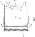
- FIG. 2 illustrates a top view of blade assembly 12 and the connection between drive cap 22 and upper housing 20.
- Blade assembly 12 includes an outer, lower, or stationary blade 42 and an inner, upper, or translating cutting blade 44.
- Cutting blade 44 is trapped between stationary blade 42 and the outer body 16.
- Cutting blade 44 is captured between stationary blade 42 and outer body 16 and reciprocates over stationary blade 42.
- Drive cap 22 has an inner surface 33c and an outer surface 46. As illustrated, drive cap 22 includes protrusions 48 and snap fasteners 50.
- Upper housing 20 includes two extensions 52 that interconnect upper housing 20 to drive cap 22.
- protrusions 48 on drive cap 22 extend into upper housing 20 to releaseably engage drive cap 22 under upper housing 20 and orient snap fasteners 50 relative to snap detents 51 on drive cap 22 and/or housing 20 (or housing 18).
- Protrusions 48, snap fasteners 50, and extensions 52 align drive cap 22 relative to lower and upper housings 18 and 20 and secure drive cap 22 into place.
- outer surfaces 24 and 32 of lower and upper housings 18 and 20 are continuous with outer surface 46 of drive cap 22, creating a smooth outer body 16. In this way, a smooth surface along outer body 16 is created without any transitions along lower housing 18, upper housing 20, and/or drive cap 22.
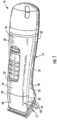
- blade assembly 12 is hingedly connected to the forward end 26 of lower housing 18 or outer body 16 for movement between an operating position ( FIGS. 3 and 4 ) and a retracted position, shown in dotted outline.
- the retracted position provides access to drive cap 22 and facilitates removal of drive cap 22.
- pulling drive cap 22 away from upper housing 20 releases snap fasteners 50 and the joint slides along extensions 52 and protrusions 48.
- the retracted position of blade assembly 12 facilitates removal of drive cap 22 from hair clipper 10.
- the retracted position and removal of drive cap 22 enhances access to blade assembly 12 or drive assembly 14 for maintenance and/or cleaning.
- Any suitable mounting arrangement can be employed to couple blade assembly 12 to outer body 16.
- a portion of upper housing 20 is broken away to show the inner surface 33 of upper housing 20.
- blade assembly 12 includes a stationary blade 42 and a movable or translating cutting blade 44 which laterally reciprocates or oscillates relative to stationary blade 42 to cut hair.
- Cutting blade 44 is coupled to and driven by drive assembly 14, which interconnects cutting blade 44 to a drive motor 54 ( FIG. 4 ).
- Any conventional blade assembly 12 which is compatible with drive assembly 14 can be employed.
- Drive assembly 14 is fixedly supported within the hollow interior of the outer body 16, e.g. , by a pair of screws or adhesive.
- Drive assembly 14 operatively extends between a drive motor 54 and cutting blade 44 to reciprocate cutting blade 44 relative to stationary blade 42 in response to energization of motor 54.
- motor 54 receives electrical energy from an electrical storage device (e.g., battery or electrical outlet) to oscillate at least one blade in blade assembly 12.
- an electrical storage device e.g., battery or electrical outlet
- hair clipper 10 is either configured with a cord that plugs into an outlet or is cordless and contains a capacitor, battery, and/or other electrical storage device.
- the forward end 34 of upper housing 20 terminates rearwardly of the forward end 26 of lower housing 18.
- Forward end segments 40 extend between the forward end 34 of upper housing 20 to blade assembly 12 and form a surface to join drive cap 22 to lower housing 18.
- Lower housing 18, upper housing 20, and/or drive cap 22 have one or more snap detents 51 and/or laterally extending forward edge portions or extensions 52 ( FIG. 4 ).
- Extensions 52 join the forward ends 34 of the lateral edges 38 of upper housing 20 to drive cap 22.
- Extensions 52 join drive cap 22 to forward end segments 40 of lower housing 18.
- the forward termination of upper housing 20 provides access to drive assembly 14 for cleaning, lubrication, and replacement without requiring tools.
- Upper housing 20 terminates rearwardly of forward end 26 of lower housing 18, blade assembly 12, and drive assembly 14 to provide access to these components when removed.
- drive cap 22 extends forwardly from extension 52 on forward end 34 ( FIG. 1 ) of upper housing 20.
- Drive cap 22 extends laterally between forward end segments 40 of lower housing 18.
- Drive cap 22 seamlessly couples to lateral edges 30 of lower housing 18 and forward end 34 of upper housing 20 to form outer body 16.
- snap fasteners 50 extend from drive cap 22 and couple into snap detent 51 of upper housing 20.
- drive cap 22 couples to lower housing 18 and/or upper housing 20 with one or more snap fasteners 50 on inner surface 33 ( e.g. , an inner surface 33 of drive cap 22, lower housing 18, and/or upper housing 20) to snap detents 51 on an inner surface 33 ( e.g. , of lower housing 18, upper housing 20, and/or drive cap 22).
- Snap fasteners 50 can couple drive cap 22 to lower housing 18 and/or upper housing 20.
- Drive cap 22 provides a cover for the top of blade assembly 12 and extends rearwardly from blade assembly 12 to cover a portion of drive assembly 14.
- Drive cap 22 includes a forward edge 56 adjacent to blade assembly 12 and a rearward edge 58 adjacent to forward end 34 of upper housing 20.
- each snap fastener 50 and each snap detent 51 is located on inner surfaces 33 of housings 18, 20, and/or drive cap 22.
- no snap fasteners 50 or detents 51 are located on outer surfaces 24, 32, and/or 46 of lower/upper housing 18/20 and drive cap 22, respectively, are smooth.
- drive cap 22 includes an inner surface 33c or interior 60 and an exterior 62 which, when drive cap 22 is assembled on outer body 16, extends in smooth merging relation to outer surfaces 24 and 32 of lower and upper housings 18 and 20, respectively.
- Drive cap 22 includes a rearward edge 58 which is located adjacent to forward end segments 40 of upper housing 20 when outer body 16 is assembled (see FIG. 1 ).
- Drive cap 22 includes snap fasteners 50 to interconnect drive cap 22 with upper housing 20.
- One or more protrusions 48 extend from drive cap 22 to facilitate the alignment and joining of drive cap 22 to upper housing 20 and/or lower housing 18.
- One or more recesses 64 are formed in lateral edges 66 of drive cap 22. Lateral edges 66 join drive cap 22 to forward end segments 40 of lower housing 18. Recesses 64 in lateral edges 66 join with a lip projection on adjacent forward end segments 40 of lower housing 18.
- Rearward edge 58 and lateral edges 66 of drive cap 22 couple to forward end 34 of upper housing 20 and forward end segments 40 of lower housing 18, respectively, to form outer body 16.
- Drive cap 22 includes a forward edge 56 located adjacent to blade assembly 12. Exterior 62 of drive cap 22 extends rearward from forward edge 56 and is rearwardly convergent and merges smoothly (without transitions) with outer surface 24 of lower housing 18 and outer surface 32 of upper housing 20 of outer body 16.
- lower and upper housings 18 and 20 and drive cap 22 have outer surfaces 24, 32, and 46 that merge, such that when lower and upper housings 18 and 20 are coupled to drive cap 22, outer surfaces 24, 32, and/or 46 merge into a smooth exterior housing with curvilinear transitions ( e.g. , without acute or sharp angles).
- Drive cap 22 and lower and upper housings 18 and 20 include resilient structures and/or cavities to secure drive cap 22.
- the resilient structures and cavities include protrusions 48, voids 49, snap fasteners 50, snap detents 51, extensions 52, slots 53, recesses 64, projections, and other structures or cavities to resiliently align and connect drive cap 22 in removable assembled relation to outer body 16.
- These structures enable an aligned coupling of drive cap 22 within outer body 16 so that exterior 62 of drive cap 22 blends smoothly with outer surfaces 24 and 32 of lower and upper housings 18 and 20.
- this configuration enables the nondestructive removal of drive cap 22 from outer body 16 without the use of tools.
- the removal of drive cap 22 facilitates access to drive assembly 14. For example, removal of drive cap 22 facilitates lubrication, cleaning, and/or replacement of drive assembly 14.
- such structure includes, on lower housing 18, upper housing 20, and/or drive cap 22, laterally spaced guiding and supporting extensions 52 or projections.
- Drive cap 22 may include one or more protrusions 48.
- a first protrusion 48 may extend downwardly or inwardly from laterally spaced lateral edges 66.
- protrusions 48 are releasably engaged under upper housing 20 and/or lower housing 18 to orient drive cap 22 with respect to outer body 16.
- drive cap 22 may include slots 53 to receive extensions 52 and/or voids 49 to receive protrusions 48.
- Upper housing 20 can include laterally spaced extensions 52 which extend forwardly beyond forward end 34 and from the underside or inside surface 33b of upper housing 20.
- drive cap 22 can include protrusions 48 which extend inwardly from inside surface 33c or interior 60. Protrusions 48 extend laterally outward in adjacent relation to voids 49, thereby assisting in laterally locating drive cap 22 in proper relation to upper housing 20 to form outer body 16.
- drive cap 22 is fabricated of the same plastic as is employed in lower and/or upper housings 18 and 20.
- drive cap 22 is constructed from a plastic material that is thicker than the same plastic material used in lower and upper housings 18 and 20.
- the thickness and relatively short length of drive cap 22 and the otherwise non-semi-circular construction of drive cap 22, as compared to lower and upper housing 18 and 20, is such that drive cap 22 is resilient as compared to lower and upper housing 18 and 20.
- drive cap 22 and lower and upper housings 18 and 20 each comprise the same material, and drive cap 22 has a thickness that is greater than a maximum thickness of either lower or upper housing 18 or 20.
- drive cap 22 may be the same or a different material than lower and/or upper housings 18 and/or 20.
- drive cap 22 is a different material and/or a thicker material to make drive cap 22 more resilient to fracture relative to lower and upper housings 18 and 20.
- drive cap 22 is made from a resilient thermoset polymer material and lower and/or upper housings 18 and 20 are formed from a thermoplastic material.
- drive cap 22 is constructed from a thermoplastic and lower and/or upper housings 18 and 20 are formed from a thermoset material.
- drive cap 22 can be removed by manually manipulating the cover or drive cap 22 to release snap fasteners 50 located within snap detents 51. In this way, the user can move drive cap 22 upwardly and away from lower housing 18 and forwardly from upper housing 20 without the use of a tool.
- Hinged connection of blade assembly 12 to outer body 16, as described in reference to FIG. 3 facilitates manual removal of drive cap 22 from outer body 16.
- blade assembly 12 is hingedly coupled to lower or upper housing 18 or 20 and releaseably rotated from an operating position to a retracted position. More particularly, displacement of blade assembly 12 to the retracted position, as shown in the dotted lines of FIG. 3 , enables improved grasp of drive cap 22 and facilitates manual removal from outer body 16. In other words, the retracted position provides access to inner surface 33c of drive cap 22.
- drive cap 22 includes a snap fastener 50 that couples to a snap detent 51 in upper housing 20.
- one of upper housing 20 and drive cap 22 has snap fastener 50 on inner surface 33 (e.g. , inner surface 33b on upper housing 20 or inner surface 33c on drive cap 22) and the other of upper housing 20 and drive cap 22 has snap detent 51 on its inner surface 33.
- Snap fastener 50 and snap detent 51 on inner surfaces 33b and 33c cooperate to releasably couple upper housing 20 to drive cap 22.
- upper housing 20 may include one or more extensions 52 configured to align with slots 53 in drive cap 22 to orient drive cap 22 with respect to upper housing 20.
- Drive cap 22 includes one or more protrusions 48 configured to align with voids 49 in upper housing 20 to orient drive cap 22 with respect to upper housing 20. As illustrated, drive cap 22 couples to upper housing 20 with various snap fasteners 50 and snap detents 51. Similar coupling techniques can be used to join drive cap 22 to forward end segments 40 of lower housing 18.
- drive cap 22 is illustrated detached from upper housing 20.
- the interior 60 of drive cap 22 includes one or more snap fasteners 50 configured to couple with a snap detent 51 in upper housing 20.
- upper housing 20 has one or more snap fasteners 50 configured to couple with a snap detent 51 in drive cap 22.
- Upper housing 20 has one or more extensions 52 configured to couple with one or more surfaces or slots 53 on the rearward edge 58 of drive cap 22.
- drive cap 22 has one or more protrusions 48 configured to couple with one or more surfaces or voids 49 of the forward end 34 of upper housing 20.
- the forward end 34 of upper housing 20 couples to the rearward edge 58 of drive cap 22.
- Upper housing 20 and drive cap 22 may have a mating recess 64 about lateral edges 66 configured to receive lower housing 18. Edges 38 of upper housing 20 and lateral edges 66 of drive cap 22 may form a continuous recess 64 so that lower housing 18 can form a continuous lip projection to couple to upper housing 20 and drive cap 22.
- One or more fastener holes 68 in upper housing 20 may be configured to receive fasteners from lower housing 18 to join housings 18 and 20 and form outer body 16. Drive cap 22 then slides into upper housing 20. When snap fasteners 50 are received in lower and/or upper housing 18 or 20, drive cap 22 completes outer body 16.
- the various protrusions 48 and/or extensions 52 on lower housing 18, upper housing 20, and drive cap 22 ensure that the parts are correctly aligned and held firmly in place ( e.g. , hermetically seal) when snap fastener 50 secures into snap detent 51.
- extensions 52 align and/or couple with slots 53 on drive cap 22 to couple drive cap 22 to upper housing 20.
- protrusions 48 align and/or couple with voids 49 on upper housing 20 to couple and/or fluidly seal drive cap 22 seamlessly onto upper housing 20.
- a fluid seal may prevent air, water, or other fluids from entering the hollow interior of outer body 16.
- the seal may be hermetic and/or fluid to make clippers 10 that are, e.g., water resistant.
- Similar protrusions 48, voids 49, snap fasteners 50, snap detents 51, extensions 52, and/or slots 53 are envisioned for forward end segments 40 of lower housing 18.
- FIG. 7 illustrates drive cap 22 coupled to upper housing 20 and joined by snap fasteners 50.
- Snap fasteners 50 enable secure non-permanent coupling of drive cap 22 and upper housing 20 with a smooth finish. Because no screws are used to couple upper housing 20 to drive cap 22, the exterior surface along outer body 16 appears to have a smooth finish without any transitions. The joint is secured by protrusions 48, snap fasteners 50, and/or extensions 52, but is not permanently joined. A user can remove drive cap 22 from upper housing 20 to clean, for example, motor 54 and/or other components.
- FIG. 8 illustrates an isolated drive cap 22. From this perspective, exterior 62 of drive cap 22 is visible. Snap fasteners 50 are visible from the rearward edge 58 of drive cap 22. Protrusions 48 couple to voids 49 in upper housing 20 to help stabilize the joint and align drive cap 22 with respect to upper housing 20. Extensions 52 on upper housing 20 couple with slots 53 to further stabilize and orient drive cap 22. The forward edge 56 of drive cap 22 couples to the forward end 34 of upper housing 20. Lateral edges 66 of drive cap 22 couple to the forward end segments 40 of lower housing 18 to complete outer body 16.
- lower and upper housings 18 and 20 and/or drive cap 22 are non-permanently joined by snap fasteners 50 coupled to snap detents 51, protrusions 48 coupled to voids 49, and extensions 52 coupled to slots 53, such that lower and upper housings 18 and 20, and drive cap 22 have no permanent joints to each other and are releasably coupled.
- the term "coupled” means the joining of two components directly or indirectly to one another. Such joining may be stationary in nature or movable in nature. Such joining may be achieved with the two members and any additional intermediate members being integrally formed as a single unitary body with one another or with the two members or the two members and any additional member being attached to one another. Such joining may be permanent in nature or alternatively may be removable or releasable in nature.
Landscapes
- Life Sciences & Earth Sciences (AREA)
- Forests & Forestry (AREA)
- Engineering & Computer Science (AREA)
- Mechanical Engineering (AREA)
- Dry Shavers And Clippers (AREA)
Claims (15)
- Haarschneider (10), umfassend:ein Gehäuse mit einem oberen Gehäuse (20), das mit einem unteren Gehäuse (18) verbunden ist, wobei das obere Gehäuse (20) eine Innenfläche (33b) aufweist;eine Antriebsbaugruppe (14);einen Klingensatz (12), der mit der Antriebsbaugruppe (14) verbunden ist und eine Außenklinge (42) und eine Innenklinge (44) aufweist, die über der Außenklinge (42) schwingt; undeine Antriebskappe (22), die mit einem Schnappverschlusselement (50) an der Innenfläche (33b) des oberen Gehäuses (20) mit dem oberen Gehäuse (20) verbunden ist, das sich lösbar mit einer Schnappraste (51) an einer Innenfläche (33c) der Antriebskappe (22) verbindet, wobei die Antriebskappe (22) die Antriebsbaugruppe (14) teilweise umgibt, um eine Barriere zu schaffen, die das Eindringen von Fremdkörpern in die Antriebsbaugruppe (14) verhindert;dadurch gekennzeichnet, dass die Antriebskappe (22) ferner Vorsprünge (48), die sich mit Hohlräumen (49) an dem oberen Gehäuse (20) verbinden, und Verlängerungen (52) an einem der Antriebskappe (22) und des oberen Gehäuses (20) umfasst, die sich mit Schlitzen (53) an dem der Antriebskappe (22) und des oberen Gehäuse (20) verknüpfen, um die Antriebskappe (22) an dem oberen Gehäuse (20) abzudichten.
- Haarschneider (10) nach Anspruch 1, wobei das obere Gehäuse (20) durch ein oder mehrere Schnappverschlusselemente mit dem unteren Gehäuse (18) verbunden ist.
- Haarschneider (10) nach Anspruch 1, wobei die Antriebskappe (22) ein Kunststoffmaterial umfasst.
- Haarschneider (10) nach Anspruch 3, wobei:-(i) das Kunststoffmaterial in der Antriebskappe (22) bruchfester als ein Material ist, das für die Konstruktion des oberen oder unteren Gehäuses (20, 18) verwendet wird; oder(ii) das obere Gehäuse (20) ein Kunststoffmaterial aufweist, das aus dem gleichen Kunststoffmaterial besteht, das in der Antriebskappe (22) enthalten ist.
- Haarschneider (10) nach Anspruch 3, wobei das obere Gehäuse (20), das untere Gehäuse (18) und die Antriebskappe (22) jeweils aus einem duroplastischen Material gebildet sind.
- Haarschneider (10) nach Anspruch 1, umfassend:ein elektrisches Speichergerät zur Speicherung elektrischer Energie;die Antriebsbaugruppe (14), die mit dem elektrischen Speichergerät verbunden ist, wobei die Antriebsbaugruppe (14) elektrische Energie aus dem elektrischen Speichergerät verwendet, um die Innenklinge (44) über der Außenklinge (42) zu schwingen; undwobei das Gehäuse das elektrische Speichergerät und die Antriebsbaugruppe umgibt,wobei das obere Gehäuse (20) eine Außenfläche (32) aufweist;das untere Gehäuse (18) eine Innenfläche (33a) und eine Außenfläche (24) aufweist, wobei das untere Gehäuse (18) mit einem oder mehreren Schnappverschlusselementen mit dem oberen Gehäuse (20) verbunden ist, wobei eines des oberen Gehäuses (20) und des unteren Gehäuses (18) ein Schnappverschlusselement an der Innenfläche (33a, 33b) aufweist und das andere des oberen Gehäuses (20) und des unteren Gehäuses (18) eine Schnappraste an der Innenfläche (33a, 33b) aufweist, wobei das Schnappverschlusselement und die Schnappraste an der Innenfläche (33a, 33b) verbunden sind, um das obere Gehäuse (20) lösbar mit dem unteren Gehäuse (18) zu verbinden; unddie Antriebskappe (22) eine Außenfläche (46) aufweist.
- Haarschneider (10) nach Anspruch 6, der ferner eine Aussparung (64) in einer Seitenkante (66) der Antriebskappe (22) aufweist, wobei die Aussparung (64) die Antriebskappe (22) mit Vorsprüngen im unteren Gehäuse (18) verbindet.
- Haarschneider (10) nach Anspruch 6, wobei die Antriebskappe (22), das obere Gehäuse (20) und das untere Gehäuse (18) Außenflächen (32, 24, 46) aufweisen, die ineinanderfließen, so dass, wenn die Antriebskappe (22), das obere und das untere Gehäuse (20, 18) verbunden sind, die Außenflächen (32, 24, 46) zu einem glatten Außengehäuse mit krummlinigen Übergängen ineinanderfließen.
- Haarschneider (10) nach Anspruch 6, wobei die Antriebskappe (22), das obere Gehäuse (20) und das untere Gehäuse (18) aus dem gleichen Material gebildet sind, und wobei die Antriebskappe (22) eine Dicke aufweist, die größer als eine maximale Dicke des oberen Gehäuses (20) oder des unteren Gehäuses (18) ist.
- Haarschneider (10) nach Anspruch 1, wobei der Klingensatz (12) an dem Gehäuse angelenkt ist, wobei der Klingensatz (12) lösbar von einer Betriebsposition in eine eingefahrene Position gedreht wird, wobei die eingefahrene Position Zugang zu der Innenfläche (33c) der Antriebskappe (22) bietet.
- Haarschneider (10) nach Anspruch 1, wobei sich keine Schnappverschlusselemente und keine Schnapprasten auf einer Außenfläche (46) der Antriebskappe (22), des oberen Gehäuses (20) oder des unteren Gehäuses (18) befinden; oder
Haarschneider (10) nach Anspruch 6, wobei jedes Schnappverschlusselement (50) und jede Schnappraste (51) an Innenflächen (33a-c) der Antriebskappe (22), des oberen Gehäuses (20) oder des unteren Gehäuses (18) angeordnet sind. - Haarschneider (10) nach Anspruch 1, umfassend:ein elektrisches Speichergerät zur Speicherung elektrischer Energie;die Antriebsbaugruppe (14), die mit dem elektrischen Speichergerät verbunden ist, wobei die Antriebsbaugruppe (14) elektrische Energie aus dem elektrischen Speichergerät verwendet, um die Innenklinge (44) über der Außenklinge (42) zu schwingen; undwobei das Gehäuse das elektrische Speichergerät und die Antriebsbaugruppe (14) umgibt, wobei das obere Gehäuse (20) eine Außenfläche (32) aufweist;das untere Gehäuse (18) eine Innenfläche (33a) und eine Außenfläche (24) aufweist, wobei das untere Gehäuse (18) mit einem oder mehreren Schnappverschlusselementen mit dem oberen Gehäuse (20) verbunden ist, wobei eines des oberen Gehäuses (20) und des unteren Gehäuses (18) ein Schnappverschlusselement an der Innenfläche (33a, 33b) aufweist und das andere des oberen Gehäuses (20) und des unteren Gehäuses (18) eine Schnappraste an der Innenfläche (33a, 33b) umfasst, wobei das Schnappverschlusselement und die Schnappraste an der Innenfläche (33a, 33b) verbunden sind, um das obere Gehäuse (20) lösbar mit dem unteren Gehäuse (18) zu verbinden; unddie Antriebskappe (22) eine Außenfläche (46) aufweist.
- Haarschneider (10) nach Anspruch 12, wobei:-(i) die Antriebskappe (22), das obere Gehäuse (20) und das untere Gehäuse (18) durch Schnappverschlusselemente, die mit Schnapprasten verbunden sind, Vorsprünge, die mit Hohlräumen verbunden sind, und Verlängerungen, die mit Schlitzen verbunden sind, nicht dauerhaft verbunden sind, wobei die Antriebskappe (22), das obere Gehäuse (20) und das untere Gehäuse (18) keine dauerhaften Verbindungen miteinander aufweisen und lösbar verbunden sind; oder(ii) sich keine Schnappverschlusselemente und Schnapprasten an Außenflächen der Antriebskappe (22), des oberen Gehäuses (20) oder des unteren Gehäuses (18) befinden.
- Haarschneider (10) nach Anspruch 1, der ferner eine Aussparung (64) in einer Seitenkante (38) des oberen Gehäuses (20) aufweist, wobei die Aussparung (64) so ausgestaltet ist, dass sie das untere Gehäuse (18) aufnimmt und sich mit ihm verbindet.
- Haarschneider (10) nach Anspruch 14, ferner umfassend eine Aussparung (64) in einer Seitenkante (66) der Antriebskappe (22), wobei die Aussparung (64) in der Seitenkante (66) der Antriebskappe (22) und die Aussparung (64) in der Seitenkante (38) des oberen Gehäuses (20) zusammen eine durchgehende Aussparung bilden.
Priority Applications (1)
| Application Number | Priority Date | Filing Date | Title |
|---|---|---|---|
| EP25162825.1A EP4541527A3 (de) | 2018-12-14 | 2019-12-13 | Schnappbefestigung einer antriebskappenanordnung |
Applications Claiming Priority (2)
| Application Number | Priority Date | Filing Date | Title |
|---|---|---|---|
| US201862779970P | 2018-12-14 | 2018-12-14 | |
| PCT/US2019/066322 WO2020124000A1 (en) | 2018-12-14 | 2019-12-13 | Snap fastened drive cap assembly |
Related Child Applications (2)
| Application Number | Title | Priority Date | Filing Date |
|---|---|---|---|
| EP25162825.1A Division EP4541527A3 (de) | 2018-12-14 | 2019-12-13 | Schnappbefestigung einer antriebskappenanordnung |
| EP25162825.1A Division-Into EP4541527A3 (de) | 2018-12-14 | 2019-12-13 | Schnappbefestigung einer antriebskappenanordnung |
Publications (3)
| Publication Number | Publication Date |
|---|---|
| EP3894149A1 EP3894149A1 (de) | 2021-10-20 |
| EP3894149A4 EP3894149A4 (de) | 2022-10-19 |
| EP3894149B1 true EP3894149B1 (de) | 2025-04-23 |
Family
ID=71073687
Family Applications (2)
| Application Number | Title | Priority Date | Filing Date |
|---|---|---|---|
| EP25162825.1A Pending EP4541527A3 (de) | 2018-12-14 | 2019-12-13 | Schnappbefestigung einer antriebskappenanordnung |
| EP19895608.8A Active EP3894149B1 (de) | 2018-12-14 | 2019-12-13 | Anordnung einer schnappverschlussantriebskappe |
Family Applications Before (1)
| Application Number | Title | Priority Date | Filing Date |
|---|---|---|---|
| EP25162825.1A Pending EP4541527A3 (de) | 2018-12-14 | 2019-12-13 | Schnappbefestigung einer antriebskappenanordnung |
Country Status (7)
| Country | Link |
|---|---|
| US (3) | US11235482B2 (de) |
| EP (2) | EP4541527A3 (de) |
| CN (1) | CN113165194A (de) |
| CA (1) | CA3121245A1 (de) |
| ES (1) | ES3028608T3 (de) |
| MX (2) | MX2021005955A (de) |
| WO (1) | WO2020124000A1 (de) |
Families Citing this family (6)
| Publication number | Priority date | Publication date | Assignee | Title |
|---|---|---|---|---|
| EP3461603A1 (de) * | 2017-09-29 | 2019-04-03 | Koninklijke Philips N.V. | Haarschneidevorrichtung |
| USD895898S1 (en) * | 2018-04-16 | 2020-09-08 | Andis Company | Hair trimmer |
| USD898998S1 (en) * | 2018-04-19 | 2020-10-13 | Andis Company | Hair clipper |
| MX2021005955A (es) | 2018-12-14 | 2021-10-13 | Andis Co | Conjunto de tapa de transmisión fijada a presión. |
| IT201900011250A1 (it) * | 2019-07-09 | 2021-01-09 | Gamma Piu S R L | Tagliacapelli elettrico |
| USD972215S1 (en) * | 2020-05-22 | 2022-12-06 | Andis Company | Hair clipper |
Family Cites Families (22)
| Publication number | Priority date | Publication date | Assignee | Title |
|---|---|---|---|---|
| US1956042A (en) * | 1931-11-27 | 1934-04-24 | Oster Mfg Co John | Hair clipper |
| US2182597A (en) * | 1938-01-13 | 1939-12-05 | Oster John Mfg Co | Hair clipper |
| NL6509065A (de) * | 1965-07-14 | 1967-01-16 | ||
| US3520059A (en) * | 1967-10-05 | 1970-07-14 | Allway Tools | Knife handle for adjustable blade |
| US3589007A (en) * | 1969-02-24 | 1971-06-29 | Wahl Clipper Corp | Electric hair clipper |
| US4549352A (en) * | 1982-11-10 | 1985-10-29 | Kyushu Hitachi Maxell, Ltd. | Washable electric shaver |
| US4541538A (en) * | 1984-04-16 | 1985-09-17 | General Electric Company | Wiring device covers |
| US5088200A (en) * | 1990-10-11 | 1992-02-18 | Andis Company | Hair trimmer having a low-friction rotary drive |
| US5230153A (en) * | 1990-10-11 | 1993-07-27 | Andis Company | Mounting bracket for hair trimmers |
| US6076263A (en) * | 1997-07-17 | 2000-06-20 | Andis Company | Hair clipper with resiliently removable cover portion enclosing a blade drive assembly |
| US6742262B2 (en) * | 2001-04-09 | 2004-06-01 | Conair Corporation | Detachable and adjustable blade assembly |
| US6640811B2 (en) * | 2001-12-03 | 2003-11-04 | Yong Hoon Cho | Portable nail care device |
| US6862810B2 (en) * | 2002-06-21 | 2005-03-08 | Andis Company | Hair-trimmer with releasable cutting head |
| KR200337194Y1 (ko) * | 2003-09-18 | 2003-12-31 | 정 슈안 프리시젼 컴퍼니 리미티드 | 전지 세트 구조를 갖는 전동 이발기 |
| JP4538676B2 (ja) * | 2008-02-25 | 2010-09-08 | パナソニック電工株式会社 | ヘアカッター |
| US9561596B2 (en) * | 2011-09-19 | 2017-02-07 | Wahl Clipper Corporation | Multi-part hair clipper housing lid |
| PL2614938T3 (pl) * | 2012-01-12 | 2020-06-29 | Spectrum Brands, Inc. | Elektryczny trymer do włosów |
| CN103507094A (zh) * | 2013-09-27 | 2014-01-15 | 何东波 | 一种电动电推剪 |
| CA2945100A1 (en) * | 2014-04-16 | 2015-10-22 | Bic-Violex Sa | Handles for shavers to be releasably connected to shaving cartridges. |
| KR101616420B1 (ko) | 2014-06-24 | 2016-04-28 | 삼성중공업 주식회사 | 프로펠러 캐비테이션 유기 기진력 저감형 선박 |
| KR20160000150U (ko) * | 2014-07-07 | 2016-01-15 | 황이삭 | 전동 헤어 클리퍼 |
| MX2021005955A (es) * | 2018-12-14 | 2021-10-13 | Andis Co | Conjunto de tapa de transmisión fijada a presión. |
-
2019
- 2019-12-13 MX MX2021005955A patent/MX2021005955A/es unknown
- 2019-12-13 ES ES19895608T patent/ES3028608T3/es active Active
- 2019-12-13 WO PCT/US2019/066322 patent/WO2020124000A1/en not_active Ceased
- 2019-12-13 EP EP25162825.1A patent/EP4541527A3/de active Pending
- 2019-12-13 CA CA3121245A patent/CA3121245A1/en active Pending
- 2019-12-13 US US16/714,126 patent/US11235482B2/en active Active
- 2019-12-13 CN CN201980080711.5A patent/CN113165194A/zh active Pending
- 2019-12-13 EP EP19895608.8A patent/EP3894149B1/de active Active
-
2021
- 2021-05-20 MX MX2025007618A patent/MX2025007618A/es unknown
- 2021-12-22 US US17/559,104 patent/US11904485B2/en active Active
-
2024
- 2024-01-12 US US18/411,462 patent/US12251846B2/en active Active
Also Published As
| Publication number | Publication date |
|---|---|
| CA3121245A1 (en) | 2020-06-18 |
| EP4541527A3 (de) | 2025-11-05 |
| EP4541527A2 (de) | 2025-04-23 |
| US20240149478A1 (en) | 2024-05-09 |
| ES3028608T3 (en) | 2025-06-19 |
| EP3894149A1 (de) | 2021-10-20 |
| US11904485B2 (en) | 2024-02-20 |
| US12251846B2 (en) | 2025-03-18 |
| MX2021005955A (es) | 2021-10-13 |
| CN113165194A (zh) | 2021-07-23 |
| MX2025007618A (es) | 2025-08-01 |
| US20220111543A1 (en) | 2022-04-14 |
| US20200189135A1 (en) | 2020-06-18 |
| WO2020124000A1 (en) | 2020-06-18 |
| US11235482B2 (en) | 2022-02-01 |
| EP3894149A4 (de) | 2022-10-19 |
Similar Documents
| Publication | Publication Date | Title |
|---|---|---|
| US12251846B2 (en) | Snap fastened drive cap assembly | |
| US5718014A (en) | Hand held motorized tool with over-molded cover | |
| US5697115A (en) | Cleaning apparatus with triangular shaped mount for attachment and quick disconnect | |
| US11597107B2 (en) | Processing head for a hair cutting appliance and combined blade unit | |
| US9174349B2 (en) | Rotary electric shaver | |
| RU2674052C1 (ru) | Связующий блок и приспособление для стрижки волос | |
| RU2518025C1 (ru) | Комбинированное устройство для бритья и подравнивания | |
| US6076263A (en) | Hair clipper with resiliently removable cover portion enclosing a blade drive assembly | |
| RU2630738C2 (ru) | Бритвенный прибор для влажного бритья | |
| MXPA97003086A (en) | Cleaning equipment with a formatriangular support for a device and disconnectionrap | |
| US20100064520A1 (en) | Modular grooming tool with dual motors | |
| EP4329995B1 (de) | Konturierhaarschneidgerät mit auswechselbaren arbeitsköpfen | |
| US20060283022A1 (en) | Electric hair clipper | |
| US20080235956A1 (en) | Hinged cutting tool configured for severing elongated foliage protruding through an opening in a screen | |
| US5706541A (en) | Watertight friction fit battery cap with cam removal | |
| WO2010120322A1 (en) | Power tool including vacuum attachment | |
| CN102416630B (zh) | 理发器 | |
| KR20100035993A (ko) | 팁 드레서용 집진 커버 | |
| CA2065488C (en) | Methods and apparatus for cleaning hair clipper blades | |
| JP4386330B2 (ja) | 替刃式かみそりホルダー | |
| CN218942272U (zh) | 一种带三角刀口的双刃雪茄剪 | |
| RU2741943C2 (ru) | Ручная машинка для стрижки волос | |
| EP3706967A1 (de) | Haarpflegegerät | |
| JP2559623Y2 (ja) | 往復式電気かみそり | |
| JPH05212164A (ja) | 電気カミソリ |
Legal Events
| Date | Code | Title | Description |
|---|---|---|---|
| STAA | Information on the status of an ep patent application or granted ep patent |
Free format text: STATUS: THE INTERNATIONAL PUBLICATION HAS BEEN MADE |
|
| PUAI | Public reference made under article 153(3) epc to a published international application that has entered the european phase |
Free format text: ORIGINAL CODE: 0009012 |
|
| STAA | Information on the status of an ep patent application or granted ep patent |
Free format text: STATUS: REQUEST FOR EXAMINATION WAS MADE |
|
| 17P | Request for examination filed |
Effective date: 20210528 |
|
| AK | Designated contracting states |
Kind code of ref document: A1 Designated state(s): AL AT BE BG CH CY CZ DE DK EE ES FI FR GB GR HR HU IE IS IT LI LT LU LV MC MK MT NL NO PL PT RO RS SE SI SK SM TR |
|
| DAV | Request for validation of the european patent (deleted) | ||
| DAX | Request for extension of the european patent (deleted) | ||
| A4 | Supplementary search report drawn up and despatched |
Effective date: 20220920 |
|
| RIC1 | Information provided on ipc code assigned before grant |
Ipc: B26B 19/02 20060101ALI20220914BHEP Ipc: B26B 19/38 20060101AFI20220914BHEP |
|
| GRAP | Despatch of communication of intention to grant a patent |
Free format text: ORIGINAL CODE: EPIDOSNIGR1 |
|
| STAA | Information on the status of an ep patent application or granted ep patent |
Free format text: STATUS: GRANT OF PATENT IS INTENDED |
|
| INTG | Intention to grant announced |
Effective date: 20241128 |
|
| GRAS | Grant fee paid |
Free format text: ORIGINAL CODE: EPIDOSNIGR3 |
|
| GRAA | (expected) grant |
Free format text: ORIGINAL CODE: 0009210 |
|
| STAA | Information on the status of an ep patent application or granted ep patent |
Free format text: STATUS: THE PATENT HAS BEEN GRANTED |
|
| AK | Designated contracting states |
Kind code of ref document: B1 Designated state(s): AL AT BE BG CH CY CZ DE DK EE ES FI FR GB GR HR HU IE IS IT LI LT LU LV MC MK MT NL NO PL PT RO RS SE SI SK SM TR |
|
| REG | Reference to a national code |
Ref country code: GB Ref legal event code: FG4D |
|
| REG | Reference to a national code |
Ref country code: CH Ref legal event code: EP |
|
| REG | Reference to a national code |
Ref country code: DE Ref legal event code: R096 Ref document number: 602019069161 Country of ref document: DE |
|
| REG | Reference to a national code |
Ref country code: IE Ref legal event code: FG4D |
|
| REG | Reference to a national code |
Ref country code: ES Ref legal event code: FG2A Ref document number: 3028608 Country of ref document: ES Kind code of ref document: T3 Effective date: 20250619 |
|
| REG | Reference to a national code |
Ref country code: NL Ref legal event code: MP Effective date: 20250423 |
|
| PG25 | Lapsed in a contracting state [announced via postgrant information from national office to epo] |
Ref country code: NL Free format text: LAPSE BECAUSE OF FAILURE TO SUBMIT A TRANSLATION OF THE DESCRIPTION OR TO PAY THE FEE WITHIN THE PRESCRIBED TIME-LIMIT Effective date: 20250423 |
|
| REG | Reference to a national code |
Ref country code: AT Ref legal event code: MK05 Ref document number: 1787361 Country of ref document: AT Kind code of ref document: T Effective date: 20250423 |
|
| PG25 | Lapsed in a contracting state [announced via postgrant information from national office to epo] |
Ref country code: PT Free format text: LAPSE BECAUSE OF FAILURE TO SUBMIT A TRANSLATION OF THE DESCRIPTION OR TO PAY THE FEE WITHIN THE PRESCRIBED TIME-LIMIT Effective date: 20250825 Ref country code: FI Free format text: LAPSE BECAUSE OF FAILURE TO SUBMIT A TRANSLATION OF THE DESCRIPTION OR TO PAY THE FEE WITHIN THE PRESCRIBED TIME-LIMIT Effective date: 20250423 |
|
| REG | Reference to a national code |
Ref country code: LT Ref legal event code: MG9D |
|
| PG25 | Lapsed in a contracting state [announced via postgrant information from national office to epo] |
Ref country code: NO Free format text: LAPSE BECAUSE OF FAILURE TO SUBMIT A TRANSLATION OF THE DESCRIPTION OR TO PAY THE FEE WITHIN THE PRESCRIBED TIME-LIMIT Effective date: 20250723 Ref country code: GR Free format text: LAPSE BECAUSE OF FAILURE TO SUBMIT A TRANSLATION OF THE DESCRIPTION OR TO PAY THE FEE WITHIN THE PRESCRIBED TIME-LIMIT Effective date: 20250724 |
|
| PG25 | Lapsed in a contracting state [announced via postgrant information from national office to epo] |
Ref country code: PL Free format text: LAPSE BECAUSE OF FAILURE TO SUBMIT A TRANSLATION OF THE DESCRIPTION OR TO PAY THE FEE WITHIN THE PRESCRIBED TIME-LIMIT Effective date: 20250423 |
|
| PG25 | Lapsed in a contracting state [announced via postgrant information from national office to epo] |
Ref country code: BG Free format text: LAPSE BECAUSE OF FAILURE TO SUBMIT A TRANSLATION OF THE DESCRIPTION OR TO PAY THE FEE WITHIN THE PRESCRIBED TIME-LIMIT Effective date: 20250423 |
|
| PG25 | Lapsed in a contracting state [announced via postgrant information from national office to epo] |
Ref country code: HR Free format text: LAPSE BECAUSE OF FAILURE TO SUBMIT A TRANSLATION OF THE DESCRIPTION OR TO PAY THE FEE WITHIN THE PRESCRIBED TIME-LIMIT Effective date: 20250423 |
|
| PG25 | Lapsed in a contracting state [announced via postgrant information from national office to epo] |
Ref country code: AT Free format text: LAPSE BECAUSE OF FAILURE TO SUBMIT A TRANSLATION OF THE DESCRIPTION OR TO PAY THE FEE WITHIN THE PRESCRIBED TIME-LIMIT Effective date: 20250423 |
|
| PG25 | Lapsed in a contracting state [announced via postgrant information from national office to epo] |
Ref country code: RS Free format text: LAPSE BECAUSE OF FAILURE TO SUBMIT A TRANSLATION OF THE DESCRIPTION OR TO PAY THE FEE WITHIN THE PRESCRIBED TIME-LIMIT Effective date: 20250723 |
|
| PG25 | Lapsed in a contracting state [announced via postgrant information from national office to epo] |
Ref country code: IS Free format text: LAPSE BECAUSE OF FAILURE TO SUBMIT A TRANSLATION OF THE DESCRIPTION OR TO PAY THE FEE WITHIN THE PRESCRIBED TIME-LIMIT Effective date: 20250823 |
|
| PG25 | Lapsed in a contracting state [announced via postgrant information from national office to epo] |
Ref country code: LV Free format text: LAPSE BECAUSE OF FAILURE TO SUBMIT A TRANSLATION OF THE DESCRIPTION OR TO PAY THE FEE WITHIN THE PRESCRIBED TIME-LIMIT Effective date: 20250423 |
|
| PGFP | Annual fee paid to national office [announced via postgrant information from national office to epo] |
Ref country code: GB Payment date: 20251229 Year of fee payment: 7 |
|
| PG25 | Lapsed in a contracting state [announced via postgrant information from national office to epo] |
Ref country code: DK Free format text: LAPSE BECAUSE OF FAILURE TO SUBMIT A TRANSLATION OF THE DESCRIPTION OR TO PAY THE FEE WITHIN THE PRESCRIBED TIME-LIMIT Effective date: 20250423 Ref country code: SM Free format text: LAPSE BECAUSE OF FAILURE TO SUBMIT A TRANSLATION OF THE DESCRIPTION OR TO PAY THE FEE WITHIN THE PRESCRIBED TIME-LIMIT Effective date: 20250423 |
|
| PGFP | Annual fee paid to national office [announced via postgrant information from national office to epo] |
Ref country code: FR Payment date: 20251226 Year of fee payment: 7 |
|
| PG25 | Lapsed in a contracting state [announced via postgrant information from national office to epo] |
Ref country code: CZ Free format text: LAPSE BECAUSE OF FAILURE TO SUBMIT A TRANSLATION OF THE DESCRIPTION OR TO PAY THE FEE WITHIN THE PRESCRIBED TIME-LIMIT Effective date: 20250423 |
|
| PG25 | Lapsed in a contracting state [announced via postgrant information from national office to epo] |
Ref country code: EE Free format text: LAPSE BECAUSE OF FAILURE TO SUBMIT A TRANSLATION OF THE DESCRIPTION OR TO PAY THE FEE WITHIN THE PRESCRIBED TIME-LIMIT Effective date: 20250423 |
|
| REG | Reference to a national code |
Ref country code: DE Ref legal event code: R097 Ref document number: 602019069161 Country of ref document: DE |
|
| PG25 | Lapsed in a contracting state [announced via postgrant information from national office to epo] |
Ref country code: RO Free format text: LAPSE BECAUSE OF FAILURE TO SUBMIT A TRANSLATION OF THE DESCRIPTION OR TO PAY THE FEE WITHIN THE PRESCRIBED TIME-LIMIT Effective date: 20250423 Ref country code: SK Free format text: LAPSE BECAUSE OF FAILURE TO SUBMIT A TRANSLATION OF THE DESCRIPTION OR TO PAY THE FEE WITHIN THE PRESCRIBED TIME-LIMIT Effective date: 20250423 |
|
| PG25 | Lapsed in a contracting state [announced via postgrant information from national office to epo] |
Ref country code: IT Free format text: LAPSE BECAUSE OF FAILURE TO SUBMIT A TRANSLATION OF THE DESCRIPTION OR TO PAY THE FEE WITHIN THE PRESCRIBED TIME-LIMIT Effective date: 20250423 |
|
| PLBE | No opposition filed within time limit |
Free format text: ORIGINAL CODE: 0009261 |
|
| STAA | Information on the status of an ep patent application or granted ep patent |
Free format text: STATUS: NO OPPOSITION FILED WITHIN TIME LIMIT |
|
| REG | Reference to a national code |
Ref country code: CH Ref legal event code: L10 Free format text: ST27 STATUS EVENT CODE: U-0-0-L10-L00 (AS PROVIDED BY THE NATIONAL OFFICE) Effective date: 20260304 |
|
| 26N | No opposition filed |
Effective date: 20260126 |
|
| PGFP | Annual fee paid to national office [announced via postgrant information from national office to epo] |
Ref country code: ES Payment date: 20260102 Year of fee payment: 7 |
|
| PGFP | Annual fee paid to national office [announced via postgrant information from national office to epo] |
Ref country code: DE Payment date: 20251229 Year of fee payment: 7 |