EP3894241B1 - Reifen mit überwachungsvorrichtung - Google Patents
Reifen mit überwachungsvorrichtung Download PDFInfo
- Publication number
- EP3894241B1 EP3894241B1 EP19845717.8A EP19845717A EP3894241B1 EP 3894241 B1 EP3894241 B1 EP 3894241B1 EP 19845717 A EP19845717 A EP 19845717A EP 3894241 B1 EP3894241 B1 EP 3894241B1
- Authority
- EP
- European Patent Office
- Prior art keywords
- tyre
- monitoring device
- flexible support
- adhesive
- decoupling element
- Prior art date
- Legal status (The legal status is an assumption and is not a legal conclusion. Google has not performed a legal analysis and makes no representation as to the accuracy of the status listed.)
- Active
Links
Images

Classifications
-
- B—PERFORMING OPERATIONS; TRANSPORTING
- B60—VEHICLES IN GENERAL
- B60C—VEHICLE TYRES; TYRE INFLATION; TYRE CHANGING; CONNECTING VALVES TO INFLATABLE ELASTIC BODIES IN GENERAL; DEVICES OR ARRANGEMENTS RELATED TO TYRES
- B60C23/00—Devices for measuring, signalling, controlling, or distributing tyre pressure or temperature, specially adapted for mounting on vehicles; Arrangement of tyre inflating devices on vehicles, e.g. of pumps or of tanks; Tyre cooling arrangements
- B60C23/02—Signalling devices actuated by tyre pressure
- B60C23/04—Signalling devices actuated by tyre pressure mounted on the wheel or tyre
- B60C23/0491—Constructional details of means for attaching the control device
- B60C23/0493—Constructional details of means for attaching the control device for attachment on the tyre
-
- B—PERFORMING OPERATIONS; TRANSPORTING
- B60—VEHICLES IN GENERAL
- B60C—VEHICLE TYRES; TYRE INFLATION; TYRE CHANGING; CONNECTING VALVES TO INFLATABLE ELASTIC BODIES IN GENERAL; DEVICES OR ARRANGEMENTS RELATED TO TYRES
- B60C23/00—Devices for measuring, signalling, controlling, or distributing tyre pressure or temperature, specially adapted for mounting on vehicles; Arrangement of tyre inflating devices on vehicles, e.g. of pumps or of tanks; Tyre cooling arrangements
- B60C23/02—Signalling devices actuated by tyre pressure
- B60C23/04—Signalling devices actuated by tyre pressure mounted on the wheel or tyre
-
- B—PERFORMING OPERATIONS; TRANSPORTING
- B29—WORKING OF PLASTICS; WORKING OF SUBSTANCES IN A PLASTIC STATE IN GENERAL
- B29D—PRODUCING PARTICULAR ARTICLES FROM PLASTICS OR FROM SUBSTANCES IN A PLASTIC STATE
- B29D30/00—Producing pneumatic or solid tyres or parts thereof
- B29D30/0061—Accessories, details or auxiliary operations not otherwise provided for
-
- B—PERFORMING OPERATIONS; TRANSPORTING
- B60—VEHICLES IN GENERAL
- B60C—VEHICLE TYRES; TYRE INFLATION; TYRE CHANGING; CONNECTING VALVES TO INFLATABLE ELASTIC BODIES IN GENERAL; DEVICES OR ARRANGEMENTS RELATED TO TYRES
- B60C23/00—Devices for measuring, signalling, controlling, or distributing tyre pressure or temperature, specially adapted for mounting on vehicles; Arrangement of tyre inflating devices on vehicles, e.g. of pumps or of tanks; Tyre cooling arrangements
- B60C23/06—Signalling devices actuated by deformation of the tyre, e.g. tyre mounted deformation sensors or indirect determination of tyre deformation based on wheel speed, wheel-centre to ground distance or inclination of wheel axle
- B60C23/061—Signalling devices actuated by deformation of the tyre, e.g. tyre mounted deformation sensors or indirect determination of tyre deformation based on wheel speed, wheel-centre to ground distance or inclination of wheel axle by monitoring wheel speed
-
- B—PERFORMING OPERATIONS; TRANSPORTING
- B60—VEHICLES IN GENERAL
- B60C—VEHICLE TYRES; TYRE INFLATION; TYRE CHANGING; CONNECTING VALVES TO INFLATABLE ELASTIC BODIES IN GENERAL; DEVICES OR ARRANGEMENTS RELATED TO TYRES
- B60C23/00—Devices for measuring, signalling, controlling, or distributing tyre pressure or temperature, specially adapted for mounting on vehicles; Arrangement of tyre inflating devices on vehicles, e.g. of pumps or of tanks; Tyre cooling arrangements
- B60C23/06—Signalling devices actuated by deformation of the tyre, e.g. tyre mounted deformation sensors or indirect determination of tyre deformation based on wheel speed, wheel-centre to ground distance or inclination of wheel axle
- B60C23/064—Signalling devices actuated by deformation of the tyre, e.g. tyre mounted deformation sensors or indirect determination of tyre deformation based on wheel speed, wheel-centre to ground distance or inclination of wheel axle comprising tyre mounted deformation sensors, e.g. to determine road contact area
-
- B—PERFORMING OPERATIONS; TRANSPORTING
- B60—VEHICLES IN GENERAL
- B60C—VEHICLE TYRES; TYRE INFLATION; TYRE CHANGING; CONNECTING VALVES TO INFLATABLE ELASTIC BODIES IN GENERAL; DEVICES OR ARRANGEMENTS RELATED TO TYRES
- B60C23/00—Devices for measuring, signalling, controlling, or distributing tyre pressure or temperature, specially adapted for mounting on vehicles; Arrangement of tyre inflating devices on vehicles, e.g. of pumps or of tanks; Tyre cooling arrangements
- B60C23/20—Devices for measuring or signalling tyre temperature only
-
- C—CHEMISTRY; METALLURGY
- C09—DYES; PAINTS; POLISHES; NATURAL RESINS; ADHESIVES; COMPOSITIONS NOT OTHERWISE PROVIDED FOR; APPLICATIONS OF MATERIALS NOT OTHERWISE PROVIDED FOR
- C09J—ADHESIVES; NON-MECHANICAL ASPECTS OF ADHESIVE PROCESSES IN GENERAL; ADHESIVE PROCESSES NOT PROVIDED FOR ELSEWHERE; USE OF MATERIALS AS ADHESIVES
- C09J7/00—Adhesives in the form of films or foils
- C09J7/20—Adhesives in the form of films or foils characterised by their carriers
- C09J7/22—Plastics; Metallised plastics
- C09J7/25—Plastics; Metallised plastics based on macromolecular compounds obtained otherwise than by reactions involving only carbon-to-carbon unsaturated bonds
-
- C—CHEMISTRY; METALLURGY
- C09—DYES; PAINTS; POLISHES; NATURAL RESINS; ADHESIVES; COMPOSITIONS NOT OTHERWISE PROVIDED FOR; APPLICATIONS OF MATERIALS NOT OTHERWISE PROVIDED FOR
- C09J—ADHESIVES; NON-MECHANICAL ASPECTS OF ADHESIVE PROCESSES IN GENERAL; ADHESIVE PROCESSES NOT PROVIDED FOR ELSEWHERE; USE OF MATERIALS AS ADHESIVES
- C09J7/00—Adhesives in the form of films or foils
- C09J7/30—Adhesives in the form of films or foils characterised by the adhesive composition
- C09J7/38—Pressure-sensitive adhesives [PSA]
- C09J7/381—Pressure-sensitive adhesives [PSA] based on macromolecular compounds obtained by reactions involving only carbon-to-carbon unsaturated bonds
- C09J7/383—Natural or synthetic rubber
-
- B—PERFORMING OPERATIONS; TRANSPORTING
- B29—WORKING OF PLASTICS; WORKING OF SUBSTANCES IN A PLASTIC STATE IN GENERAL
- B29D—PRODUCING PARTICULAR ARTICLES FROM PLASTICS OR FROM SUBSTANCES IN A PLASTIC STATE
- B29D30/00—Producing pneumatic or solid tyres or parts thereof
- B29D30/0061—Accessories, details or auxiliary operations not otherwise provided for
- B29D2030/0072—Attaching fasteners to tyres, e.g. patches, in order to connect devices to tyres
-
- B—PERFORMING OPERATIONS; TRANSPORTING
- B29—WORKING OF PLASTICS; WORKING OF SUBSTANCES IN A PLASTIC STATE IN GENERAL
- B29D—PRODUCING PARTICULAR ARTICLES FROM PLASTICS OR FROM SUBSTANCES IN A PLASTIC STATE
- B29D30/00—Producing pneumatic or solid tyres or parts thereof
- B29D30/0061—Accessories, details or auxiliary operations not otherwise provided for
- B29D2030/0077—Directly attaching monitoring devices to tyres before or after vulcanization, e.g. microchips
-
- C—CHEMISTRY; METALLURGY
- C09—DYES; PAINTS; POLISHES; NATURAL RESINS; ADHESIVES; COMPOSITIONS NOT OTHERWISE PROVIDED FOR; APPLICATIONS OF MATERIALS NOT OTHERWISE PROVIDED FOR
- C09J—ADHESIVES; NON-MECHANICAL ASPECTS OF ADHESIVE PROCESSES IN GENERAL; ADHESIVE PROCESSES NOT PROVIDED FOR ELSEWHERE; USE OF MATERIALS AS ADHESIVES
- C09J2203/00—Applications of adhesives in processes or use of adhesives in the form of films or foils
- C09J2203/326—Applications of adhesives in processes or use of adhesives in the form of films or foils for bonding electronic components such as wafers, chips or semiconductors
-
- C—CHEMISTRY; METALLURGY
- C09—DYES; PAINTS; POLISHES; NATURAL RESINS; ADHESIVES; COMPOSITIONS NOT OTHERWISE PROVIDED FOR; APPLICATIONS OF MATERIALS NOT OTHERWISE PROVIDED FOR
- C09J—ADHESIVES; NON-MECHANICAL ASPECTS OF ADHESIVE PROCESSES IN GENERAL; ADHESIVE PROCESSES NOT PROVIDED FOR ELSEWHERE; USE OF MATERIALS AS ADHESIVES
- C09J2203/00—Applications of adhesives in processes or use of adhesives in the form of films or foils
- C09J2203/354—Applications of adhesives in processes or use of adhesives in the form of films or foils for automotive applications
-
- C—CHEMISTRY; METALLURGY
- C09—DYES; PAINTS; POLISHES; NATURAL RESINS; ADHESIVES; COMPOSITIONS NOT OTHERWISE PROVIDED FOR; APPLICATIONS OF MATERIALS NOT OTHERWISE PROVIDED FOR
- C09J—ADHESIVES; NON-MECHANICAL ASPECTS OF ADHESIVE PROCESSES IN GENERAL; ADHESIVE PROCESSES NOT PROVIDED FOR ELSEWHERE; USE OF MATERIALS AS ADHESIVES
- C09J2301/00—Additional features of adhesives in the form of films or foils
- C09J2301/10—Additional features of adhesives in the form of films or foils characterized by the structural features of the adhesive tape or sheet
- C09J2301/12—Additional features of adhesives in the form of films or foils characterized by the structural features of the adhesive tape or sheet by the arrangement of layers
- C09J2301/124—Additional features of adhesives in the form of films or foils characterized by the structural features of the adhesive tape or sheet by the arrangement of layers the adhesive layer being present on both sides of the carrier, e.g. double-sided adhesive tape
-
- C—CHEMISTRY; METALLURGY
- C09—DYES; PAINTS; POLISHES; NATURAL RESINS; ADHESIVES; COMPOSITIONS NOT OTHERWISE PROVIDED FOR; APPLICATIONS OF MATERIALS NOT OTHERWISE PROVIDED FOR
- C09J—ADHESIVES; NON-MECHANICAL ASPECTS OF ADHESIVE PROCESSES IN GENERAL; ADHESIVE PROCESSES NOT PROVIDED FOR ELSEWHERE; USE OF MATERIALS AS ADHESIVES
- C09J2400/00—Presence of inorganic and organic materials
- C09J2400/20—Presence of organic materials
- C09J2400/24—Presence of a foam
-
- C—CHEMISTRY; METALLURGY
- C09—DYES; PAINTS; POLISHES; NATURAL RESINS; ADHESIVES; COMPOSITIONS NOT OTHERWISE PROVIDED FOR; APPLICATIONS OF MATERIALS NOT OTHERWISE PROVIDED FOR
- C09J—ADHESIVES; NON-MECHANICAL ASPECTS OF ADHESIVE PROCESSES IN GENERAL; ADHESIVE PROCESSES NOT PROVIDED FOR ELSEWHERE; USE OF MATERIALS AS ADHESIVES
- C09J2409/00—Presence of diene rubber
-
- C—CHEMISTRY; METALLURGY
- C09—DYES; PAINTS; POLISHES; NATURAL RESINS; ADHESIVES; COMPOSITIONS NOT OTHERWISE PROVIDED FOR; APPLICATIONS OF MATERIALS NOT OTHERWISE PROVIDED FOR
- C09J—ADHESIVES; NON-MECHANICAL ASPECTS OF ADHESIVE PROCESSES IN GENERAL; ADHESIVE PROCESSES NOT PROVIDED FOR ELSEWHERE; USE OF MATERIALS AS ADHESIVES
- C09J2475/00—Presence of polyurethane
-
- C—CHEMISTRY; METALLURGY
- C09—DYES; PAINTS; POLISHES; NATURAL RESINS; ADHESIVES; COMPOSITIONS NOT OTHERWISE PROVIDED FOR; APPLICATIONS OF MATERIALS NOT OTHERWISE PROVIDED FOR
- C09J—ADHESIVES; NON-MECHANICAL ASPECTS OF ADHESIVE PROCESSES IN GENERAL; ADHESIVE PROCESSES NOT PROVIDED FOR ELSEWHERE; USE OF MATERIALS AS ADHESIVES
- C09J2479/00—Presence of polyamine or polyimide
- C09J2479/08—Presence of polyamine or polyimide polyimide
- C09J2479/086—Presence of polyamine or polyimide polyimide in the substrate
Definitions
- the present invention relates to a tyre provided with a monitoring device, for example a device comprising a pressure sensor and/or a temperature and/or acceleration and/or deformation sensor, on the inner surface of the tyre.
- a monitoring device for example a device comprising a pressure sensor and/or a temperature and/or acceleration and/or deformation sensor, on the inner surface of the tyre.
- a parameter of the tyre that can be monitored is the inflation pressure.
- a tyre that is not properly inflated can result in higher fuel consumption, impair vehicle manoeuvrability and cause uneven tyre wear, just to name a few of the most important problems.
- Systems have therefore been developed to monitor the inflation pressure of the tyres during use, these systems informing the driver of any drop in pressure and the consequent need to restore optimal conditions to avoid the aforementioned problems.
- tyre temperature Another parameter that can provide very important information on the condition of the tyre during use is the tyre temperature.
- An abnormal increase in temperature is a sign of the presence of critical operating conditions, which could create irreversible damage to the tyre.
- the measurement of the temperature allows recalculating the instantaneous measurement of the pressure in order to monitor the renormalized value thereof at room temperature.
- WO2004110794A1 describes a tyre provided with a monitoring device adhering to the inner surface of the tyre.
- the monitoring device described was of the rigid type (i.e. made on rigid PCB - or Printed Circuit Boards), unlike the tyre, which instead has a dynamic behaviour, with continuous and cyclic deformations.
- the rigidity of the monitoring device resulted from the need to ensure that the welding joints to the board, the metal traces through the boards, and the integrated circuits themselves did not break due to bending.
- DE 10 2011 003707 discloses a monitoring device (3), comprising electronic elements (31,32,33) embedded in a gel (8) enclosed by a film (4) and a sealing layer (5), so forming an assembly adhered to a tyre by an adhesive layer (10).
- the problem faced concerned both (a) the provision of a safe and stable connection between the tyre and the monitoring device and (b) the avoidance of a rigid housing for the sensor unit.
- the proposed solution was to embed the electronic elements (31,32,33) in a gel (8) to solve problem (b) together with enclosing the gel (8) within a film (4) and a sealing layer (5) and to adhere the film (4) to the inner surface of the tyre by an adhesive layer (10) to solve problem (a).
- Monitoring devices have been proposed made on flexible or even extensible supports for mounting inside the tyre or on the rim as described, for example, in US4862486A , US2007013503A1 , US2010271191A1 , US2014118134A1 and US2015097662A1 .
- WO2106/042580 discloses a monitoring device on flexible support bonded to the inner surface of a tyre by means of a double-sided adhesive tape comprising an acrylic foam layer with a layer of acrylic adhesive coated on both its sides, such as for example a 3M PT1500 tape.
- the Applicant has performed a long series of tests with tyres comprising monitoring devices made on flexible supports, extensible or not, fixed on the inner surface of the tyre, verifying that these devices exhibit various problems of resistance and/or durability over time in the different conditions of use of the tyre.
- the Applicant has verified that the monitoring devices made on flexible and extensible supports may undergo damage, such as breakage of the connection circuits between the components of the device itself.
- the Applicant observed that devices made on flexible but not extensible supports (for example polyimide and polyethylene naphthalate) maintained the conductivity of the connection circuits between the different components of the device, but showed bad adhesion, with numerous and evident points of detachment from the inner surface of the tyre; on the other hand, devices made on flexible and also extensible supports (for example in polyurethane) showed good adhesion, but interruptions in conductivity due to breakages and/or interruptions in the conductive tracks of the electronic circuit.
- flexible but not extensible supports for example polyimide and polyethylene naphthalate
- the Applicant believes that the millions of cycles to which a monitoring device made on a flexible support, extensible or not, fixed on the inner surface of the tyre is subjected during the rotation of the tyre in its different conditions of use (speed, load, etc.) produce forces of different nature and intensity on the device itself.
- the Applicant has observed that during the passage in the contact area the device undergoes cyclical composite forces in the longitudinal (and also lateral) direction, due to the deformation that the tyre undergoes during the rotation in contact with the road.
- the device undergoes stretching/extension and compression/shortening cycles when entering and leaving the footprint area, due to deformations of the inner surface of the tyre.
- the components of the monitoring device may also contribute to the aforementioned composite cyclical stresses suffered by the device itself, due to the inertial effects caused by the masses of these components when subjected to the speed variations in the longitudinal (and also lateral) direction that occur when the monitoring device enters and leaves the footprint area.
- the Applicant found that the use of an acrylic double-sided adhesive tape comprising a viscoelastic acrylic foam resistant to dynamic shear stresses was able to ensure a good adhesion of the monitoring device on non-extensible flexible supports to the inner surface of the tyre.
- a first aspect of the present invention relates to a tyre as defined in claim 1.
- the decoupling element is able to withstand, in particular, the dynamic composite shear stresses which are generated (in different directions) due to the cyclic deformation that the tyre undergoes at the footprint.
- it appears to act as a substrate which withstands these shear stresses so as to deform (e.g. stretch and/or shorten) cyclically without breaking, so as to reduce or cancel the stresses transmitted to the flexible support and generated by the deformations of the inner surface, and/or withstand the stresses transmitted by the flexible support and generated by the inertial effects due to the masses of the components of the monitoring device.
- This has advantageously allowed using also non-extensible supports, more suitable for the purpose of adequately protecting the integrity of the conductive electrical connection tracks of the various components of the monitoring device.
- this allowed obtaining excellent adhesion conditions of the monitoring device to the inner surface of the tyre, without significant detachments.
- Said decoupling element is an acrylic double-sided adhesive tape and may comprise (i) a viscoelastic acrylic foam or (ii) a substrate of expanded polymeric material (or even in the form of a gel), such as EPDM rubber or polyurethane or (iii) at least one acrylic adhesive layer with a thickness equal to or greater than 0.4 mm, or (iv) combinations thereof, said acrylic double-sided adhesive tape being resistant to a dynamic shear stress (for example measured according to ASTM D-1002) greater than 50 kPa, preferably greater of 150 kPa, for example between 50 and 3000 kPa.
- a dynamic shear stress for example measured according to ASTM D-1002
- the present invention relates to a method for installing a monitoring device made on a flexible support (preferably non-extensible) on a tyre having an inner surface of substantially toroidal shape, the method being defined in claim 14.
- the expression “monitoring device” indicates any electrical, electronic or piezoelectric device capable of measuring and/or processing and/or storing and/or transmitting externally (for example to a fixed unit present on the vehicle, or a mobile device such as a smartphone, or a unit positioned in a point by which said vehicle passes) at least one characteristic parameter of the tyre, in digital or analogue form.
- the characteristic parameter may be an instantaneous value or a value averaged over time, and may relate to:
- the monitoring device may comprise an electronic unit comprising at least one sensor for measuring at least one characteristic parameter of the tyre (for example a pressure sensor, a temperature sensor, an accelerometer, a motion sensor, a deformation sensor or a speed sensor), and/or an electronic memory that contains tyre identification data (for example a chip or a transponder), and at least one transmitter for sending the measured data to an external unit.
- at least one sensor for measuring at least one characteristic parameter of the tyre for example a pressure sensor, a temperature sensor, an accelerometer, a motion sensor, a deformation sensor or a speed sensor
- an electronic memory that contains tyre identification data (for example a chip or a transponder)
- the monitoring device may further comprise at least one power supply device.
- power supply device means a component structured to supply electricity to the electronic unit, which may comprise one or more accumulators, where the energy to be supplied is pre-accumulated (e.g. batteries or capacitors), and/or may comprise an in situ electricity generator and/or receiver suitable for directly powering the electronic unit and/or recharging the accumulators (such as an energy recovery device, or energy scavenging or harvesting, or an electromagnetic induction charger).
- the power supply device may comprise one or more electrical energy accumulators, more preferably comprises from two to four electrical energy accumulators, and even more preferably comprises two electrical energy accumulators.
- the electronic unit and the power supply device are fixed on the flexible support of the monitoring device and are electrically connected through an electrical connection circuit.
- the electrical connection circuit is fixed on the flexible support, more preferably printed on said flexible support with a conductive ink, even more preferably printed by screen printing, lithographic, ink-jet technology, etc.
- the electrical connection circuit comprises copper conducting tracks, preferably obtained by chemical etching of a thin layer (e.g. a few tens of microns) of copper.
- the flexible support may be made with an elastomeric or thermoplastic material, resistant to the operating temperatures expected for the tyre, typically included within a wide range which may go from about -40°C for winter use, up to about 150-160°C for sports use. More particularly, it is preferable to use materials without first and/or second order phase transitions (e.g. melting, glass transition) in the temperature range expected for the desired use.
- first and/or second order phase transitions e.g. melting, glass transition
- flexible support generally means a support made of a material (including a layered/composite material) which, if used for the construction of a square-shaped sheet having a side significantly greater than the circumferential extension of the area of entry or exit from the footprint area of a tyre (for example a slab with a surface area of 120 mm x 120 mm) and with a thickness equal to the support, allows such a sheet to conform - at room temperature - to a cylindrical surface with a radius smaller than the normal radius of curvature of a tyre inflated to its nominal pressure (for example a cylindrical surface with a radius of 200 mm, preferably 100 mm, more preferably 50) without breaking or undergoing permanent deformation.
- a material including a layered/composite material
- non-extensible support generally means a support with a thickness of between about 10 ⁇ m and about 400 ⁇ m, preferably between about 50 ⁇ m and about 200 ⁇ m, made with a material (including a layered/composite material) having elasticity tensile modulus preferably higher than 0.1 GPa, more preferably higher than 0.5 GPa at 23°C.
- said flexible support is a film of an elastomeric or thermoplastic material selected from nylon, PET, PEN, polyimide, and polyurethane material. Silicon (or other semiconductor) foils may also be used.
- Such flexible supports have proven to be suitable for technologies in which the electrical connection tracks are moulded or deposited on the support or chemically etched, the pre-fabricated electronic components are fixed by gluing, and the connection between the components and the electrical connection tracks may be made using conductive adhesives and/or soldering with tin or alloys thereof (for example tin-bismuth).
- the flexible support is made of materials based on polyimide, polyetherimide, fluoropolymers or polyester, in particular semi-aromatic polyesters such as polyethylene terephthalate, polybutylene terephthalate, polytrimethylene terephthalate and polyethylene naphthalate.
- Polyimide supports are commercially available, for example, from Dupont under the Kapton TM brand.
- Polyester supports are commercially available from Teijin under the Teonex TM brand.
- the flexible support may be made in a variety of not particularly limited shapes.
- the flexible support may have, for example, a square, rectangular, rhomboid, circular shape, or a combination thereof to form particular shapes such as a Z or M shape.
- edges of the flexible support may be at right angles, or, preferably, they may be chamfered, cut or rounded.
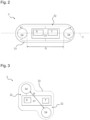
- the flexible support has an elongated rectangular or cigar shape, i.e. rectangular with rounded edges, as shown in Figure 2 .
- the flexible support has a Z shape as shown in Figure 3 , or a square shape as shown in Figure 4 .
- the dimensions of the flexible support are not particularly limited, and depend on the dimensions of the electronic unit and the power supply device.
- the dimensions of the flexible support exhibit a length of between 20 and 150 mm, preferably between 40 and 120 mm, and a width of between 10 and 90 mm, preferably between 20 and 50 mm.
- the length of the flexible support is advantageously 30, 35, 40, 45, 50, 55, 60, 65, 70, 75, 80, 85, 90, 95, 100, 105 or 110 mm.
- the width of the flexible support is advantageously 10, 15, 20, 25, 30, 35, 40, 45, 50, 55, 60, 65, 70, 75, 80, 85 or 90 mm.
- a decoupling element is interposed between the monitoring device and the inner surface of the tyre.
- the decoupling element is an acrylic double-sided adhesive tape.
- This acrylic double-sided adhesive tape withstands a dynamic shear stress measured according to ASTM D-1002) greater than 50 kPa, preferably greater than 150 kPa, for example between 50 and 3000 kPa.
- the decoupling element may be an acrylic double-sided adhesive tape comprising a viscoelastic acrylic foam with a thickness equal to or greater than 0.4 mm.
- decoupling element is represented by the 3M TM VHB TM adhesive tapes of the 4941 family, the 4956 family and the 5952 family, or by the 3M TM adhesive tapes of the RP45 family and the RP62 family, or by the Nitto Hyperjoint adhesive tapes of the H8004-H8008-H8012-H9004-H9008-H9012 family.
- Such tapes consist of a conformable acrylic foam adhesive on both sides.
- a PSA acrylic adhesive for example, the 3M TM 9469, 3M TM 468, 3M TM 93430 or Nitto 5925 adhesives
- 3M TM 9469, 3M TM 468, 3M TM 93430 or Nitto 5925 adhesives may be further applied to one or both of the surfaces of the above tapes.
- the decoupling element may be an acrylic double-sided adhesive tape comprising a substrate of expanded polymeric material (or even in the form of a gel) with a thickness equal to or greater than 0.4 mm, such as for example an expanded EPDM rubber or an expanded polyurethane, made double-sided by means of acrylic adhesive layers spread on both surfaces of the substrate.
- EPDM foam rubber derives from a family of synthetic rubbers obtained by copolymerization of ethylene and propylene in the presence of an expanding agent, generally hydrocarbons, CO 2 or other mixtures.
- the expanded polyurethane derives from a family of polymers characterized by the presence of urethane bonds (-N-CO-O-) and obtained by reacting in the presence of an expanding agent di-, tri-, poly-isocyanates with a polyol, typically a polyether polyol, obtained by polymerization of an epoxide, or a polyester polyol, obtained by polycondensation of multifunctional carboxylic acids and polyhydroxyl compounds.
- a polyol typically a polyether polyol, obtained by polymerization of an epoxide, or a polyester polyol, obtained by polycondensation of multifunctional carboxylic acids and polyhydroxyl compounds.
- a soft spongy material comprising at its interior closed or open cells characterized by a density of between 10 and 800 kg/m 3 , preferably between 20 and 700 kg/m 3 .
- Non-limiting examples of foamed EPDM rubber useful for the purposes of the present invention available on the market are represented by layers of foamed EPDM rubber produced by the company Tekspan Automotive, such as for example a layer of EPDM SE30 rubber (for example made double-sided with PSA acrylic adhesives arranged on both surfaces of the layer).
- Non-limiting examples of polyurethane foam useful for the purposes of the present invention available on the market are represented by layers of expanded polyurethane of the Cirene line produced by the company Cires SpA, such as for example the layers of expanded polyurethane Cirene 20, 25 and 30 (for example, made double-sided by means of PSA acrylic adhesives arranged on both surfaces of the layer), and by the 3M TM adhesive tapes of the "Double Coated Urethane Foam Tapes" family 4004-4008-4016-4026-4032-4052-4056-4085.
- decoupling element is represented by an acrylic double-sided adhesive tape comprising at least one layer of acrylic adhesive with a thickness equal to or greater than 0.4 mm such as, for example, the 3M TM adhesive tapes of the Extreme Sealing 4411 and 4412 family, made double-sided with a PSA acrylic adhesive (for example 3M TM 9469, 3M TM 468, 3M TM 93430 or Nitto 5925 adhesives).
- 3M TM adhesive tapes of the Extreme Sealing 4411 and 4412 family made double-sided with a PSA acrylic adhesive (for example 3M TM 9469, 3M TM 468, 3M TM 93430 or Nitto 5925 adhesives).
- the thickness of the decoupling element is preferably between 0.4 and 2.4 mm, more preferably between 0.6 and 2.2 mm, even more preferably between 0.8 and 2,0 mm, and advantageously between 1.0 and 1.8 mm.
- the other dimensions of the decoupling element, length and width depend on the dimensions of the flexible support of the monitoring device.
- the length and width of the decoupling element are preferably at least equal to the length and width of the flexible support of the monitoring device. More preferably, the length and/or width of the decoupling element are greater than the length and/or the width, respectively, of the flexible support.
- the length and/or width of the decoupling element respectively exceeds the length and width of the flexible support by at least 0.5 mm, preferably by at least 2 mm, and more preferably by a range of between 3 and 5 mm.
- any adhesive used for the decoupling element there are no particular limitations to the features of any adhesive used for the decoupling element, provided that it is resistant to the operating temperatures expected for the tyre, typically included within a wide range which, as mentioned above, may go from about -40°C for winter use, up to about 150-160°C for sports use.
- a protective layer is added on the monitoring device to cover and protect the components of the device (electronic devices, conductive tracks, accumulators, etc.).
- the protective layer is not particularly limited: films of polymeric material, such as a covering layer of nylon (Nylon cast film Domo TM Filmon TM CSX18), laminated with an acrylic adhesive, may be used for this purpose.
- the length and width of the protective layer depend on the size of the flexible support of the monitoring device.
- the length and width of the protective layer are preferably at least equal to the length and width of the flexible support. More preferably, the length and/or width of the protective layer are greater than the length and/or the width, respectively, of the flexible support.
- the length and/or width of the protective layer respectively exceeds the length and width of the flexible support by at least 0.5 mm, preferably by at least 2 mm, and more preferably by a range of between 3 and 5 mm.
- the method according to the present invention may be applied to tyres of any type and may be advantageously implemented by the user when old tyres are replaced with new ones. This is possible because the operation of inserting the device into the tyre can be carried out simply and quickly and does not necessarily require execution by specialized personnel.
- the portion of the inner surface on which the monitoring device is installed may be advantageously selected in an area where the bending stresses of the tyre are relatively low.
- a portion at a crown area of the tyre preferably in the proximity of the equatorial plane of the tyre, is preferred.
- the monitoring device may be installed on a portion of the inner surface at a bead area of the tyre.
- the installation of the monitoring device is carried out at a clean portion of the inner surface of the tyre, in the absence of adhesion promoters (or primers).
- the clean surface portion may be obtained, for example, by cleaning with detergents, and/or solvents, and/or by mechanical action, and/or by laser polishing action.
- a protective film may be arranged on the green tyre upstream of the vulcanisation, at the inner surface portion intended for the installation of the monitoring device.
- the protective film keeps the inner surface portion of the tyre substantially free from pollution by detaching agents (or in any case from dirtying or undesired substances from the vulcanisation process), and is then removed downstream of the vulcanisation process, before installation of the monitoring device.
- Such a film may be made of a material resistant to the operating conditions of temperature and pressure typical of the vulcanisation process, such as for example nylon or polyester.
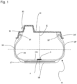
- Figure 1 shows a wheel comprising a tyre 11, of the type normally known as "tubeless”, in other words without an inner tube, and a support rim 12.
- This tyre is inflated by means of an inflation valve 13 positioned, for example, on the channel of said rim.
- the tyre 11, of which figure 1 is a schematic representation, has an internally hollow toroidal structure formed by a plurality of components.
- a metal or textile carcass structure 16 has two beads 14 and 14', each formed along an inner circumferential edge of the carcass structure 16 for fixing the tyre 11 to the corresponding support rim 12 of the wheel.
- Each of the beads 14 and 14' comprising at least one annular reinforcement core 15 and 15', known as a bead core.
- the carcass structure 16 is formed by at least one reinforcement ply which contains textile or metal cords which extend axially from one bead 14 to the other 14' in a toroidal profile, and which has each of its ends associated with a corresponding bead core 15 and 15'.
- the aforementioned cords are located substantially on the planes containing the rotation axis of the tyre.
- the belt structure 17 comprises two belt strips (not shown in Figure 1 ) which incorporate a plurality of reinforcement cords, normally metal cords, which are parallel to each other in each strip and intersect with respect to the adjacent strip, oriented in a way such as to form a predetermined angle with respect to a circumferential direction.
- At least one further reinforcement layer (not shown in Figure 1 ) to the radially outermost belt strip, said additional layer by incorporating a plurality of reinforcement cords, normally textile cords, arranged at an angle of a few degrees with respect to a circumferential direction, covered and joined together by means of an elastomeric material.
- a tread band 18 is applied, formed by an elastomeric material and usually having a tread pattern on the radially outermost surface for the rolling contact of the tyre with the road.
- two sidewalls 19 and 19' of elastomeric material are positioned on the carcass structure in axially opposite lateral positions.
- the inner surface of the tyre is normally coated with a liner 111, that is, at least one layer of air-tight elastomeric material.
- the tyre may comprise other known elements, for example additional reinforcement elements, rubber fillers, etc., according to the specific model of the tyre.
- the system for monitoring the tyre usually comprises, in general terms, a fixed unit, preferably positioned on the vehicle in which the tyre is mounted, and a mobile unit, i.e. the monitoring device 3 containing the sensor, associated with the surface of the liner 111 of the tyre 11, as shown in Figure 1 , by means of the decoupling element 4.
- the monitoring device 3 comprises at least one electronic unit 31 comprising a sensor S for measuring at least one characteristic parameter of the tyre (for example pressure, temperature, acceleration, deformation, etc.), a transmitter T for sending data to the fixed unit, and a power supply device comprising at least one accumulator 34, for supplying electrical energy to the electronic unit 31.
- a sensor S for measuring at least one characteristic parameter of the tyre (for example pressure, temperature, acceleration, deformation, etc.)
- a transmitter T for sending data to the fixed unit
- a power supply device comprising at least one accumulator 34, for supplying electrical energy to the electronic unit 31.
- the senor may be a model FXTH870911DT1 sensor marketed by NXP Semiconductors ® , suitable for detecting all three physical quantities: temperature, pressure and acceleration, in particular at least the radial component and the tangential component of the acceleration.
- the transmitter T may be a Bluetooth transmitter model SmartBond DA1458 marketed by Dialog Semiconductor ® .
- Figures 2-4 show two accumulators 34, but the monitoring device 3 may also comprise only one accumulator 34, or even more than two accumulators, such as for example three or four accumulators arranged symmetrically with respect to the electronic unit 31.
- the accumulators 34 may be represented by electric batteries, for example by button batteries of the CR2032HR type marketed by Maxell ® (capacity 200 mAh, weight 3g, diameter and thickness 20x3.2mm), or BR1632A marketed by Panasonic ® (capacity 120mAh, 1.5 g, 16x3.2mm).
- the typical voltage is equal to about 3V, and the operating temperature range is from -40°C to + 125°C.
- the electronic unit 31 and the accumulators 34 are electrically connected through an electrical connection circuit 32 schematically shown in Figures 2-4 .
- the tracks of the electrical connection circuit 32 are made with a conductive ink (e.g. DuPont ® 5025 silver conductive ink) printed with a screen printing technique directly on the flexible substrate 33.
- a conductive ink e.g. DuPont ® 5025 silver conductive ink
- the electronic unit 31 and the accumulator or accumulators 34 are arranged and glued on the flexible support 33, for example by means of conductive adhesive (e.g. Henkel 3104 WXL) and structural adhesive (e.g. Henkel A312).
- conductive adhesive e.g. Henkel 3104 WXL
- structural adhesive e.g. Henkel A3112.
- two accumulators 34 are arranged on opposite sides of the electronic unit 31.
- the dimensions along the longitudinal direction and along the orthogonal dimension may be equal to 110x30mm or 80x25mm.
- the distance D between the two accumulators 34 is equal to about 70 mm in the case of dimensions 110x30mm, while for dimensions equal to 80X25mm, the distance D is equal to about 50 mm.
- the monitoring device 3 has a plan (e.g. defined by the plan of the flexible support 33) with an elongated shape along a prevailing longitudinal development direction L, and two accumulators 34 are arranged at the longitudinally opposite ends of the monitoring device 3.
- a plan e.g. defined by the plan of the flexible support 33
- two accumulators 34 are arranged at the longitudinally opposite ends of the monitoring device 3.
- the support 33 of the monitoring device 3 is made of a flexible but non-extensible material.
- the support 33 is made of polyimide or polyester (in particular polyethylene naphthalate).
- Polyimide supports are commercially available, for example, from Dupont under the Kapton TM brand.
- Polyester supports are commercially available from Teijin under the Teonex TM brand.
- a decoupling element 4 is interposed between the monitoring device 3 and the inner surface of the tyre 111.
- the decoupling element 4 is represented by adhesive tapes 3M TM VHB TM of the 4941 family, the 4956 family and the 5952 family, or by the 3M TM adhesive tapes of the RP45 family and the RP62 family, or by the Nitto Hyperjoint adhesive tapes of the H8004-H8008-H8012-H9004-H9008-H9012 family.
- the decoupling element 4 is represented by a polyurethane foam substrate of the Cirene line produced by the company Cires SpA or by an EPDM foam rubber substrate SE30 produced by the Tekspan Automotive company, made double-sided by means of acrylic adhesive layers. (for example 3M TM 9469, 3M TM 468, 3M TM 93430 or Nitto 5925 adhesives) spread on both substrate surfaces, or a double-sided polyurethane foam substrate from the 3M TM line of adhesive tapes from the "Double Coated Urethane Foam Tapes" family 4004-4008-4016-4026-4032-4052-4056-4085.
- 3M TM 9469, 3M TM 468, 3M TM 93430 or Nitto 5925 adhesives spread on both substrate surfaces, or a double-sided polyurethane foam substrate from the 3M TM line of adhesive tapes from the "Double Coated Urethane Foam Tapes" family 4004-4008-4016-4026-4032-4052
- the decoupling element 4 is represented by layers of thick acrylic adhesive such as the 3M TM 4411 and 4412 tapes, made double-sided by a PSA adhesive (for example, the 3M TM 9469, 3M TM 468, 3M TM 93430 or Nitto 5925 adhesives).
- a PSA adhesive for example, the 3M TM 9469, 3M TM 468, 3M TM 93430 or Nitto 5925 adhesives.
- the thickness of the decoupling element is preferably between 0.4 and 2.4 mm, more preferably between 0.6 and 2.2 mm, even more preferably between 0.8 and 2,0 mm, and advantageously between 1.0 and 1.8 mm.
- Test samples were made by creating a conductive track with ECM CI-1036 silver-based flexible conductive ink on rectangular substrates having dimensions 90x60 mm made with different flexible materials, both extensible and non-extensible.
- the following materials were used: Substrate 1 3M TM 8616 polyurethane tape - 100 ⁇ m thickness - provided with acrylic adhesive Flexible Extensible Substrate 2 Delstar TM EU94DS thermoplastic polyurethane film (TPU) - 80 ⁇ m thickness - without adhesive Flexible Extensible Substrate 3 Cross-linked polybutylene rubber film - 100 ⁇ m thickness - without adhesive Flexible Extensible Substrate 4 Kapton TM polyimide film - 76 ⁇ m thickness - without adhesive Flexible Non-extensible Substrate 5 Kapton TM polyimide film - 127 ⁇ m thickness - without adhesive Flexible Non-extensible Substrate 6 PET film - 127 ⁇ m thickness - without adhesive Flexible Non-exten
- the tyres used were Pirelli P ZERO TM 265/35ZR22 (103W) SC.
- a fatigue resistance test was carried out on tyres inflated to controlled pressure kept constant for the duration of the test, subjected to constant vertical load and subjected to rolling at constant speed.
- the test was carried out on an Indoor machine with a 1.7 meter diameter drum with a camber angle equal to 0°.
- test results showed that the use of substrates with flexible and extensible materials (substrates 1-3) allowed obtaining a good adhesion with acrylic adhesives (for example of the type 3M 93430), but the deformations suffered by these materials caused breakage of the conductive track, while on the contrary the use of only flexible materials (substrates 4-7) allowed preserving the conductive track, but to the expense of the adhesion which worsened visibly.
- test of example 1 was repeated, with the same materials but using a covering layer of nylon (Nylon cast film Domo TM Filmon TM CSX18) laminated with adhesive (3M TM 9502) protruding from the sample area.
- nylon ylon cast film Domo TM Filmon TM CSX18
- adhesive 3M TM 9502
- test results were therefore similar to those of example 1.
- the tested solution gave no improvement on the adhesion of the only flexible substrates (1-3) and on the integrity of the conductive track of the flexible and extensible substrates (4-7).
- the conductive tracks reported on flexible and extensible substrates tended to degrade progressively during the test, until reaching substantially infinite resistance values (i.e. until the interruption of the electrical continuity of the tracks themselves), due to the millions of footprint entry/exit cycles to which the tyre is subjected during the test.
- the conductive tracks reported on flexible and non-extensible substrates instead preserved optimal conductivity values, but the adhesion of the substrate to the tyre liner was not guaranteed, with significant detachments between substrate and adhesive, as well as between adhesive and liner, at the end of the fatigue test.
- Thickness 127 ⁇ m Without adhesive 3M TM 93430 adhesive on the inner liner side 5A Kapton TM polyimide film 3M TM VHB TM 5962, 1.6mm with two adhesive surfaces. Thickness 127 ⁇ m Without adhesive 3M TM 93430 adhesive on the inner liner side. 6A Kapton TM polyimide film 3M TM RP45, 1mm, with two adhesive surfaces. Thickness 127 ⁇ m Without adhesive 3M TM 93430 adhesive on the inner liner side. 7A Kapton TM polyimide film 3M TM RP62, 1.6mm with two adhesive surfaces. Thickness 127 ⁇ m Without adhesive 3M TM 93430 adhesive on the inner liner side
- Sample 2A showed the best results with minimal increase in endurance and no detachment, followed by samples 1A and 5A. The other samples, however, obtained good results, which met the specific requirements both in terms of adhesion to the tyre and integrity of the conductive tracks.
- test samples (1-7 of table 5) were made with substrates having a cigar shape ( Figure 2 ) having dimensions 110x30 mm made with Kapton TM polyimide film having thickness of 127 ⁇ m.
- Two Panasonic BR1632 batteries weighing approximately 1.8g and sized 16x3.2mm were glued to the ends of each sample using a covering layer of nylon (Nylon cast film Domo TM Filmon TM CSX18) laminated with adhesive (3M TM 9502).
- samples 1 and 7 without a decoupling layer were used as a comparison to verify their performance in the high speed test.
- Sample 2 was made without conductive tracks as the ability of this decoupling layer to maintain the integrity of the conductive tracks had already been demonstrated.
- samples 3-6 a conductive track was also made with silver-based flexible conductive ink ECM CI-1036.
- samples 1-2 and 7 only the adhesion capacity was assessed, as well as the possible presence of damage to the samples themselves or to the tyre.
- Adhesive Decoupling layer Notes 1 5 Adhesive tape 3M TM 93430 - Sample without conductive strips 2 7 Adhesive tape 3M TM 93430 on both sides Tekspan EPDM SE30 2mm Sample without conductive strips 3 8 Adhesive tape 3M TM 93430 on the inner liner side 3M TM VHB 5962 1.6mm The adhesive tape has only an adhesive function 4 7 3M TM VHB 5962 1.6mm The adhesive tape also performs a decoupling function 5 7 Adhesive tape 3M TM 93430 on the inner liner side 3M TM VHB 4941 1.1mm The adhesive tape has only an adhesive function 6 8 3M TM VHB 5962 1.6mm The adhesive tape (with decoupling function) was about 3mm wider than
- the tyres used were Pirelli P ZERO TM 305/30 ZR20 (103Y).
- a high speed test was carried out on inflated tyres stressed with constant vertical load, with increasing speeds and periodically increased in steps.
- the test was carried out on an Indoor machine with a 1.7 meter diameter drum with a camber angle equal to 0°.
- Samples 1 and 7 gave good adhesion features at high speed, but as shown in examples 1 and 2 they fail to guarantee a correct adhesion of the substrate in the fatigue resistance tests.
Landscapes
- Engineering & Computer Science (AREA)
- Mechanical Engineering (AREA)
- Chemical & Material Sciences (AREA)
- Organic Chemistry (AREA)
- Chemical Kinetics & Catalysis (AREA)
- Tires In General (AREA)
- Adhesives Or Adhesive Processes (AREA)
Claims (15)
- Reifen (11), der eine Innenfläche (111) und mindestens eine Überwachungsvorrichtung (3) aufweist, die an der Innenfläche (111) haftet, wobei eine solche Überwachungsvorrichtung (3) auf einem flexiblen Träger hergestellt ist, wobei die Haftung des flexiblen Trägers an die Innenfläche (111) durch ein Entkopplungselement erreicht wird, das zwischen der mindestens einen Überwachungsvorrichtung (3) und der Innenfläche (111) des Reifens (11) eingefügt ist,wobei das Entkopplungselement ein doppelseitiges Acrylklebeband ist, unddadurch gekennzeichnet, dass das doppelseitige Acrylklebeband gegenüber einer dynamischen Scherspannung von mehr als 50 kPa, gemessen nach ASTM D-1002, beständig ist.
- Reifen (11) nach Anspruch 1, wobei das doppelseitige Acrylklebeband eine Komponente umfasst, die aus der Gruppe ausgewählt ist, die aus (i) einem viskoelastischen Acrylschaum, (ii) einem Substrat aus expandiertem Polymermaterial, (iii) mindestens einer Acrylklebeschicht oder (iv) Kombinationen davon besteht, wobei die Komponente (i), (ii) und (iii) eine Dicke gleich oder größer als 0,4 mm aufweist.
- Reifen (11) nach Anspruch 1, wobei das doppelseitige Acrylklebeband gegenüber den Betriebstemperaturen des Reifens (11) von etwa -40 °C bis etwa 160 °C beständig ist.
- Reifen (11) nach Anspruch 1, wobei das doppelseitige Acrylklebeband gegenüber einer dynamischen Scherspannung von mehr als 150 kPa, beispielsweise im Bereich von 150 bis 3000 kPa, beständig ist.
- Reifen (11) nach Anspruch 2, wobei das expandierte Polymermaterial aus der Gruppe ausgewählt ist, die aus expandiertem EPDM-Kautschuk, expandiertem Polyurethan und Kombinationen davon besteht.
- Reifen (11) nach Anspruch 2, wobei das Substrat aus expandiertem Polymermaterial eine Acrylklebeschicht umfasst, die auf beide Oberflächen des Substrats beschichtet ist.
- Reifen (11) nach Anspruch 2, wobei das expandierte Polymermaterial eine Dichte im Bereich von 10 bis 800 kg/m3, bevorzugt im Bereich von 20 bis 700 kg/m3 aufweist.
- Reifen (11) nach einem der vorstehenden Ansprüche, wobei das Entkopplungselement eine Dicke, einschließlich der auf seinen Oberflächen abgelagerten Klebeschichten, im Bereich von 0,4 bis 2,4 mm, bevorzugt im Bereich von 0,6 bis 2,2 mm, bevorzugter im Bereich von 0,8 bis 2,0 mm aufweist.
- Reifen (11) nach einem der vorstehenden Ansprüche, wobei die Länge und/oder Breite des Entkopplungselements jeweils gleich oder größer als die Länge und/oder Breite des flexiblen Trägers sind.
- Reifen (11) nach einem der vorstehenden Ansprüche, wobei eine Schutzschicht auf der Überwachungsvorrichtung (3) angeordnet ist, um die Komponenten der Vorrichtung zu bedecken und zu schützen.
- Reifen (11) nach Anspruch 10, wobei die Länge und/oder Breite der Schutzschicht jeweils gleich oder größer als die Länge und/oder Breite der Überwachungsvorrichtung (3) sind.
- Reifen (11) nach Anspruch 1, wobei der flexible Träger aus einem elastomeren oder thermoplastischen Material hergestellt ist, das aus der Gruppe ausgewählt ist, die aus Nylon, Polyester, Polyimid und Polyurethan besteht.
- Reifen (11) nach Anspruch 12, wobei das elastomere oder thermoplastische Material gegenüber den Betriebstemperaturen des Reifens (11) im Bereich von etwa - 40 °C bis etwa 160 °C beständig ist.
- Verfahren zum Installieren einer Überwachungsvorrichtung (3), die auf einem flexiblen Träger an einem Reifen (11) hergestellt ist, der eine Innenfläche (111) mit im Wesentlichen toroidaler Form aufweist, wobei das Verfahren umfasst:- Auswählen eines Abschnitts der Innenfläche (111) des Reifens (11), in dem die Überwachungsvorrichtung (3) installiert werden soll;- Erreichen der Haftung zwischen dem flexiblen Träger und dem Abschnitt der Innenfläche des Reifens (11);- wobei die Haftung durch ein Entkopplungselement erreicht wird, das zwischen dem flexiblen Träger und dem Abschnitt der Innenfläche des Reifens (11) eingefügt ist,wobei das Entkopplungselement ein doppelseitiges Acrylklebeband ist, unddadurch gekennzeichnet, dass das doppelseitige Acrylklebeband gegenüber einer dynamischen Scherspannung von mehr als 50 kPa, gemessen nach ASTM D-1002, beständig ist.
- Verfahren nach Anspruch 14, wobei das Entkopplungselement die nach einem der Ansprüche 2 bis 9 definierten Eigenschaften aufweist.
Applications Claiming Priority (2)
| Application Number | Priority Date | Filing Date | Title |
|---|---|---|---|
| IT201800010943 | 2018-12-10 | ||
| PCT/IB2019/060551 WO2020121151A1 (en) | 2018-12-10 | 2019-12-09 | Tyre with monitoring device |
Publications (3)
| Publication Number | Publication Date |
|---|---|
| EP3894241A1 EP3894241A1 (de) | 2021-10-20 |
| EP3894241C0 EP3894241C0 (de) | 2025-06-04 |
| EP3894241B1 true EP3894241B1 (de) | 2025-06-04 |
Family
ID=65861543
Family Applications (1)
| Application Number | Title | Priority Date | Filing Date |
|---|---|---|---|
| EP19845717.8A Active EP3894241B1 (de) | 2018-12-10 | 2019-12-09 | Reifen mit überwachungsvorrichtung |
Country Status (4)
| Country | Link |
|---|---|
| US (1) | US20220055424A1 (de) |
| EP (1) | EP3894241B1 (de) |
| CN (2) | CN113165453A (de) |
| WO (1) | WO2020121151A1 (de) |
Families Citing this family (5)
| Publication number | Priority date | Publication date | Assignee | Title |
|---|---|---|---|---|
| CN114761260B (zh) * | 2019-12-19 | 2024-03-15 | 倍耐力轮胎股份公司 | 包括监测装置的摩托车轮胎 |
| US12304255B2 (en) * | 2020-12-07 | 2025-05-20 | Sumitomo Rubber Industries, Ltd. | Tire |
| EP4245569B1 (de) * | 2020-12-07 | 2026-01-28 | Sumitomo Rubber Industries, Ltd. | Reifen |
| WO2023228224A1 (en) * | 2022-05-27 | 2023-11-30 | Pirelli Tyre S.P.A. | Tyre comprising a monitoring device |
| DE102022208944A1 (de) * | 2022-08-29 | 2024-02-29 | Continental Reifen Deutschland Gmbh | Verfahren zur Bestimmung der Verarbeitbarkeit eines Reifens |
Family Cites Families (23)
| Publication number | Priority date | Publication date | Assignee | Title |
|---|---|---|---|---|
| WO2004065140A1 (fr) * | 2003-01-23 | 2004-08-05 | Societe De Technologie Michelin | Fixation d'un élément rigide sur un pneumatique |
| US7034403B2 (en) * | 2003-04-10 | 2006-04-25 | 3M Innovative Properties Company | Durable electronic assembly with conductive adhesive |
| US20060290505A1 (en) * | 2005-03-01 | 2006-12-28 | Kevin Conwell | RFID tire label |
| CN101198481B (zh) * | 2005-04-14 | 2010-10-20 | 株式会社普利司通 | 轮胎和轮圈的装配体及空心粒子 |
| JP4574545B2 (ja) * | 2005-12-28 | 2010-11-04 | 住友ゴム工業株式会社 | タイヤ用無線タグ装着部材、空気入りタイヤならびに空気入りタイヤとリムとの組立体 |
| BRPI0710904B1 (pt) * | 2006-04-25 | 2018-04-03 | Bridgestone Americas Tire Operations, Llc | Pneumático |
| JP4338761B2 (ja) * | 2008-01-29 | 2009-10-07 | 住友ゴム工業株式会社 | 制音具付き空気入りタイヤ |
| US20100092716A1 (en) * | 2008-10-14 | 2010-04-15 | Spychalsky Joseph J | Label with adhesive surface |
| US7937998B2 (en) * | 2009-03-19 | 2011-05-10 | Deere & Company | Sensor mount with self-tightening device |
| JP2011071389A (ja) * | 2009-09-28 | 2011-04-07 | Fujifilm Corp | タイヤ内電力発生装置及び該装置を用いたタイヤモニタリングシステム |
| DE102011003707A1 (de) * | 2011-02-07 | 2012-08-09 | Bayerische Motoren Werke Aktiengesellschaft | Fahrzeug-Luftreifen mit einer über eine Klebeverbindung an einer Innenseite des Reifens befestigten Sensoreinheit |
| KR101326584B1 (ko) * | 2011-05-25 | 2013-11-07 | (주)코아칩스 | 전기에너지 수득 장치와 이를 구비한 타이어 및 이를 이용한 전력공급방법 |
| CN202294104U (zh) * | 2011-11-04 | 2012-07-04 | 姜开春 | 一种无源轮胎监测系统 |
| US20140255681A1 (en) * | 2013-03-05 | 2014-09-11 | Avery Dennison Corporation | Differential dual functional foam tapes |
| DE102013106015A1 (de) * | 2013-06-10 | 2014-12-11 | Continental Reifen Deutschland Gmbh | Fahrzeugluftreifen |
| ES2930234T3 (es) * | 2014-09-17 | 2022-12-09 | Ste Ind S R L | Dispositivo y método de transmisión para la transmisión inalámbrica de parámetros medidos |
| FR3052708B1 (fr) * | 2016-06-21 | 2018-05-25 | Compagnie Generale Des Etablissements Michelin | Pneumatique muni d'un organe fixe a sa surface |
| FR3058677A1 (fr) * | 2016-11-17 | 2018-05-18 | Compagnie Generale Des Etablissements Michelin | Pneumatique pret a recevoir un organe a sa surface |
| JP6917232B2 (ja) * | 2017-07-24 | 2021-08-11 | 株式会社ブリヂストン | 空気入りタイヤ |
| US20190244074A1 (en) * | 2018-02-02 | 2019-08-08 | FineLine Technologies | Foam-based rfid label |
| DE102018202248A1 (de) * | 2018-02-14 | 2019-08-14 | Continental Reifen Deutschland Gmbh | Fahrzeugrad |
| KR102162631B1 (ko) * | 2018-06-28 | 2020-10-07 | (주)알판트 | 영구 부착형 uhf 대역 알에프아이디 타이어 태그 및 이의 제조 방법 |
| TWI674205B (zh) * | 2018-10-19 | 2019-10-11 | 相豐科技股份有限公司 | 輪胎電子標籤 |
-
2019
- 2019-12-09 CN CN201980080428.2A patent/CN113165453A/zh active Pending
- 2019-12-09 WO PCT/IB2019/060551 patent/WO2020121151A1/en not_active Ceased
- 2019-12-09 EP EP19845717.8A patent/EP3894241B1/de active Active
- 2019-12-09 US US17/299,587 patent/US20220055424A1/en active Pending
- 2019-12-09 CN CN202410446133.5A patent/CN118219717A/zh active Pending
Also Published As
| Publication number | Publication date |
|---|---|
| EP3894241C0 (de) | 2025-06-04 |
| CN118219717A (zh) | 2024-06-21 |
| US20220055424A1 (en) | 2022-02-24 |
| EP3894241A1 (de) | 2021-10-20 |
| WO2020121151A1 (en) | 2020-06-18 |
| CN113165453A (zh) | 2021-07-23 |
| BR112021009986A2 (pt) | 2021-08-17 |
Similar Documents
| Publication | Publication Date | Title |
|---|---|---|
| EP3894241B1 (de) | Reifen mit überwachungsvorrichtung | |
| CN111601722B (zh) | 包括电子单元的轮胎监测装置和包括所述装置的轮胎 | |
| US20060164250A1 (en) | Wireless ic tag joining method, wireless ic tag-carrying article, and vehicle | |
| JP4705560B2 (ja) | Icタグ、それを取付けた空気入りタイヤ、およびicタグの取付方法 | |
| RU2744778C1 (ru) | Шина | |
| EP2460673B1 (de) | Luftreifen und Verfahren zur Montage eines Transponders an den Luftreifen | |
| RU2762050C1 (ru) | Шина, содержащая устройство мониторинга | |
| CN112236318B (zh) | 充气轮胎和组装片 | |
| EP3505336B1 (de) | Artikel mit elektronischer komponentenaufnahme und verfahren zur herstellung | |
| CN112469574A (zh) | 充气轮胎 | |
| EP4186715B1 (de) | Reifen | |
| WO2004110794A1 (en) | Tyre equipped with a monitoring device, and method for installing the device onto the inner surface of the tyre | |
| US12583264B2 (en) | Pneumatic tire | |
| CN114761260B (zh) | 包括监测装置的摩托车轮胎 | |
| US20210309054A1 (en) | Pneumatic Tire and Method for Manufacturing the Same | |
| RU2801670C2 (ru) | Шина с устройством мониторинга | |
| US12447776B2 (en) | Pneumatic tire and method for manufacturing the same | |
| BR112021009986B1 (pt) | Pneu, e, método para instalar um dispositivo de monitoramento | |
| EP3994014B1 (de) | Reifen mit einer überwachungsvorrichtung | |
| CN111225805A (zh) | 充气轮胎 | |
| CN113785309A (zh) | 对轮胎屈伸运动的缓冲性能优良的永久附着型uhf频带rfid轮胎标签 | |
| JP2006116989A (ja) | 安全タイヤ用空気のう及び安全タイヤ | |
| KR102606333B1 (ko) | 타이어 | |
| JP2019059301A (ja) | 空気入りタイヤ |
Legal Events
| Date | Code | Title | Description |
|---|---|---|---|
| STAA | Information on the status of an ep patent application or granted ep patent |
Free format text: STATUS: UNKNOWN |
|
| STAA | Information on the status of an ep patent application or granted ep patent |
Free format text: STATUS: THE INTERNATIONAL PUBLICATION HAS BEEN MADE |
|
| PUAI | Public reference made under article 153(3) epc to a published international application that has entered the european phase |
Free format text: ORIGINAL CODE: 0009012 |
|
| STAA | Information on the status of an ep patent application or granted ep patent |
Free format text: STATUS: REQUEST FOR EXAMINATION WAS MADE |
|
| 17P | Request for examination filed |
Effective date: 20210629 |
|
| AK | Designated contracting states |
Kind code of ref document: A1 Designated state(s): AL AT BE BG CH CY CZ DE DK EE ES FI FR GB GR HR HU IE IS IT LI LT LU LV MC MK MT NL NO PL PT RO RS SE SI SK SM TR |
|
| DAV | Request for validation of the european patent (deleted) | ||
| DAX | Request for extension of the european patent (deleted) | ||
| STAA | Information on the status of an ep patent application or granted ep patent |
Free format text: STATUS: EXAMINATION IS IN PROGRESS |
|
| 17Q | First examination report despatched |
Effective date: 20230620 |
|
| RIC1 | Information provided on ipc code assigned before grant |
Ipc: B29D 30/00 20060101ALI20241023BHEP Ipc: B60C 23/04 20060101AFI20241023BHEP |
|
| GRAP | Despatch of communication of intention to grant a patent |
Free format text: ORIGINAL CODE: EPIDOSNIGR1 |
|
| STAA | Information on the status of an ep patent application or granted ep patent |
Free format text: STATUS: GRANT OF PATENT IS INTENDED |
|
| INTG | Intention to grant announced |
Effective date: 20250203 |
|
| GRAS | Grant fee paid |
Free format text: ORIGINAL CODE: EPIDOSNIGR3 |
|
| GRAA | (expected) grant |
Free format text: ORIGINAL CODE: 0009210 |
|
| STAA | Information on the status of an ep patent application or granted ep patent |
Free format text: STATUS: THE PATENT HAS BEEN GRANTED |
|
| AK | Designated contracting states |
Kind code of ref document: B1 Designated state(s): AL AT BE BG CH CY CZ DE DK EE ES FI FR GB GR HR HU IE IS IT LI LT LU LV MC MK MT NL NO PL PT RO RS SE SI SK SM TR |
|
| REG | Reference to a national code |
Ref country code: GB Ref legal event code: FG4D |
|
| REG | Reference to a national code |
Ref country code: CH Ref legal event code: EP |
|
| REG | Reference to a national code |
Ref country code: DE Ref legal event code: R096 Ref document number: 602019070859 Country of ref document: DE |
|
| REG | Reference to a national code |
Ref country code: IE Ref legal event code: FG4D |
|
| U01 | Request for unitary effect filed |
Effective date: 20250612 |
|
| U07 | Unitary effect registered |
Designated state(s): AT BE BG DE DK EE FI FR IT LT LU LV MT NL PT RO SE SI Effective date: 20250623 |
|
| PG25 | Lapsed in a contracting state [announced via postgrant information from national office to epo] |
Ref country code: ES Free format text: LAPSE BECAUSE OF FAILURE TO SUBMIT A TRANSLATION OF THE DESCRIPTION OR TO PAY THE FEE WITHIN THE PRESCRIBED TIME-LIMIT Effective date: 20250604 |
|
| PG25 | Lapsed in a contracting state [announced via postgrant information from national office to epo] |
Ref country code: NO Free format text: LAPSE BECAUSE OF FAILURE TO SUBMIT A TRANSLATION OF THE DESCRIPTION OR TO PAY THE FEE WITHIN THE PRESCRIBED TIME-LIMIT Effective date: 20250904 Ref country code: GR Free format text: LAPSE BECAUSE OF FAILURE TO SUBMIT A TRANSLATION OF THE DESCRIPTION OR TO PAY THE FEE WITHIN THE PRESCRIBED TIME-LIMIT Effective date: 20250905 |
|
| PG25 | Lapsed in a contracting state [announced via postgrant information from national office to epo] |
Ref country code: PL Free format text: LAPSE BECAUSE OF FAILURE TO SUBMIT A TRANSLATION OF THE DESCRIPTION OR TO PAY THE FEE WITHIN THE PRESCRIBED TIME-LIMIT Effective date: 20250604 |
|
| PG25 | Lapsed in a contracting state [announced via postgrant information from national office to epo] |
Ref country code: HR Free format text: LAPSE BECAUSE OF FAILURE TO SUBMIT A TRANSLATION OF THE DESCRIPTION OR TO PAY THE FEE WITHIN THE PRESCRIBED TIME-LIMIT Effective date: 20250604 |
|
| PG25 | Lapsed in a contracting state [announced via postgrant information from national office to epo] |
Ref country code: RS Free format text: LAPSE BECAUSE OF FAILURE TO SUBMIT A TRANSLATION OF THE DESCRIPTION OR TO PAY THE FEE WITHIN THE PRESCRIBED TIME-LIMIT Effective date: 20250904 |
|
| PG25 | Lapsed in a contracting state [announced via postgrant information from national office to epo] |
Ref country code: IS Free format text: LAPSE BECAUSE OF FAILURE TO SUBMIT A TRANSLATION OF THE DESCRIPTION OR TO PAY THE FEE WITHIN THE PRESCRIBED TIME-LIMIT Effective date: 20251004 |
|
| PGFP | Annual fee paid to national office [announced via postgrant information from national office to epo] |
Ref country code: GB Payment date: 20251229 Year of fee payment: 7 |
|
| PG25 | Lapsed in a contracting state [announced via postgrant information from national office to epo] |
Ref country code: SM Free format text: LAPSE BECAUSE OF FAILURE TO SUBMIT A TRANSLATION OF THE DESCRIPTION OR TO PAY THE FEE WITHIN THE PRESCRIBED TIME-LIMIT Effective date: 20250604 |
|
| PG25 | Lapsed in a contracting state [announced via postgrant information from national office to epo] |
Ref country code: CZ Free format text: LAPSE BECAUSE OF FAILURE TO SUBMIT A TRANSLATION OF THE DESCRIPTION OR TO PAY THE FEE WITHIN THE PRESCRIBED TIME-LIMIT Effective date: 20250604 |
|
| PG25 | Lapsed in a contracting state [announced via postgrant information from national office to epo] |
Ref country code: SK Free format text: LAPSE BECAUSE OF FAILURE TO SUBMIT A TRANSLATION OF THE DESCRIPTION OR TO PAY THE FEE WITHIN THE PRESCRIBED TIME-LIMIT Effective date: 20250604 |
|
| U20 | Renewal fee for the european patent with unitary effect paid |
Year of fee payment: 7 Effective date: 20251229 |
|
| PLBE | No opposition filed within time limit |
Free format text: ORIGINAL CODE: 0009261 |
|
| STAA | Information on the status of an ep patent application or granted ep patent |
Free format text: STATUS: NO OPPOSITION FILED WITHIN TIME LIMIT |
|
| REG | Reference to a national code |
Ref country code: CH Ref legal event code: L10 Free format text: ST27 STATUS EVENT CODE: U-0-0-L10-L00 (AS PROVIDED BY THE NATIONAL OFFICE) Effective date: 20260416 |