EP3894272B1 - Siège de véhicule - Google Patents
Siège de véhicule Download PDFInfo
- Publication number
- EP3894272B1 EP3894272B1 EP19831994.9A EP19831994A EP3894272B1 EP 3894272 B1 EP3894272 B1 EP 3894272B1 EP 19831994 A EP19831994 A EP 19831994A EP 3894272 B1 EP3894272 B1 EP 3894272B1
- Authority
- EP
- European Patent Office
- Prior art keywords
- reinforcement layer
- vehicle seat
- reinforcement
- outer end
- foam part
- Prior art date
- Legal status (The legal status is an assumption and is not a legal conclusion. Google has not performed a legal analysis and makes no representation as to the accuracy of the status listed.)
- Active
Links
Images


Classifications
-
- B—PERFORMING OPERATIONS; TRANSPORTING
- B60—VEHICLES IN GENERAL
- B60N—SEATS SPECIALLY ADAPTED FOR VEHICLES; VEHICLE PASSENGER ACCOMMODATION NOT OTHERWISE PROVIDED FOR
- B60N2/00—Seats specially adapted for vehicles; Arrangement or mounting of seats in vehicles
- B60N2/70—Upholstery springs ; Upholstery
- B60N2/7017—Upholstery springs ; Upholstery characterised by the manufacturing process; manufacturing upholstery or upholstery springs not otherwise provided for
-
- B—PERFORMING OPERATIONS; TRANSPORTING
- B60—VEHICLES IN GENERAL
- B60N—SEATS SPECIALLY ADAPTED FOR VEHICLES; VEHICLE PASSENGER ACCOMMODATION NOT OTHERWISE PROVIDED FOR
- B60N2/00—Seats specially adapted for vehicles; Arrangement or mounting of seats in vehicles
- B60N2/64—Back-rests or cushions
-
- B—PERFORMING OPERATIONS; TRANSPORTING
- B60—VEHICLES IN GENERAL
- B60N—SEATS SPECIALLY ADAPTED FOR VEHICLES; VEHICLE PASSENGER ACCOMMODATION NOT OTHERWISE PROVIDED FOR
- B60N2/00—Seats specially adapted for vehicles; Arrangement or mounting of seats in vehicles
- B60N2/64—Back-rests or cushions
- B60N2/643—Back-rests or cushions shape of the back-rests
-
- B—PERFORMING OPERATIONS; TRANSPORTING
- B60—VEHICLES IN GENERAL
- B60N—SEATS SPECIALLY ADAPTED FOR VEHICLES; VEHICLE PASSENGER ACCOMMODATION NOT OTHERWISE PROVIDED FOR
- B60N2/00—Seats specially adapted for vehicles; Arrangement or mounting of seats in vehicles
- B60N2/64—Back-rests or cushions
- B60N2/646—Back-rests or cushions shape of the cushion
-
- B—PERFORMING OPERATIONS; TRANSPORTING
- B60—VEHICLES IN GENERAL
- B60N—SEATS SPECIALLY ADAPTED FOR VEHICLES; VEHICLE PASSENGER ACCOMMODATION NOT OTHERWISE PROVIDED FOR
- B60N2/00—Seats specially adapted for vehicles; Arrangement or mounting of seats in vehicles
- B60N2/70—Upholstery springs ; Upholstery
-
- B—PERFORMING OPERATIONS; TRANSPORTING
- B60—VEHICLES IN GENERAL
- B60R—VEHICLES, VEHICLE FITTINGS, OR VEHICLE PARTS, NOT OTHERWISE PROVIDED FOR
- B60R21/00—Arrangements or fittings on vehicles for protecting or preventing injuries to occupants or pedestrians in case of accidents or other traffic risks
- B60R21/02—Occupant safety arrangements or fittings, e.g. crash pads
- B60R21/16—Inflatable occupant restraints or confinements designed to inflate upon impact or impending impact, e.g. air bags
- B60R21/20—Arrangements for storing inflatable members in their non-use or deflated condition; Arrangement or mounting of air bag modules or components
- B60R21/207—Arrangements for storing inflatable members in their non-use or deflated condition; Arrangement or mounting of air bag modules or components in vehicle seats
-
- B—PERFORMING OPERATIONS; TRANSPORTING
- B60—VEHICLES IN GENERAL
- B60R—VEHICLES, VEHICLE FITTINGS, OR VEHICLE PARTS, NOT OTHERWISE PROVIDED FOR
- B60R21/00—Arrangements or fittings on vehicles for protecting or preventing injuries to occupants or pedestrians in case of accidents or other traffic risks
- B60R21/02—Occupant safety arrangements or fittings, e.g. crash pads
- B60R21/16—Inflatable occupant restraints or confinements designed to inflate upon impact or impending impact, e.g. air bags
- B60R21/20—Arrangements for storing inflatable members in their non-use or deflated condition; Arrangement or mounting of air bag modules or components
- B60R21/215—Arrangements for storing inflatable members in their non-use or deflated condition; Arrangement or mounting of air bag modules or components characterised by the covers for the inflatable member
- B60R21/2165—Arrangements for storing inflatable members in their non-use or deflated condition; Arrangement or mounting of air bag modules or components characterised by the covers for the inflatable member characterised by a tear line for defining a deployment opening
-
- B—PERFORMING OPERATIONS; TRANSPORTING
- B60—VEHICLES IN GENERAL
- B60N—SEATS SPECIALLY ADAPTED FOR VEHICLES; VEHICLE PASSENGER ACCOMMODATION NOT OTHERWISE PROVIDED FOR
- B60N2/00—Seats specially adapted for vehicles; Arrangement or mounting of seats in vehicles
- B60N2/58—Seat coverings
- B60N2002/5808—Seat coverings comprising opening zones for airbags
-
- B—PERFORMING OPERATIONS; TRANSPORTING
- B60—VEHICLES IN GENERAL
- B60R—VEHICLES, VEHICLE FITTINGS, OR VEHICLE PARTS, NOT OTHERWISE PROVIDED FOR
- B60R21/00—Arrangements or fittings on vehicles for protecting or preventing injuries to occupants or pedestrians in case of accidents or other traffic risks
- B60R21/02—Occupant safety arrangements or fittings, e.g. crash pads
- B60R21/16—Inflatable occupant restraints or confinements designed to inflate upon impact or impending impact, e.g. air bags
- B60R2021/161—Inflatable occupant restraints or confinements designed to inflate upon impact or impending impact, e.g. air bags characterised by additional means for controlling deployment trajectory
Definitions
- the invention relates to a vehicle seat with a seat part and a backrest, the backrest having a foam part with a cavity for at least partially accommodating an airbag device.
- the EP 1 199 227 A1 discloses a vehicle seat having an assembly consisting of a backrest and an airbag module, the backrest having a frame, padding and a trim part, and the airbag module having a chute attached to the frame.
- the trim part is rigid, while the padding in the area of the transition to the trim part is flexible so that a gap can be formed between the trim part and the padding for the airbag to emerge from the backrest by deforming the padding.
- a safety device for motor vehicles with at least one gas bag module that can be integrated into a vehicle seat, which comprises a prefabricated module unit that can be handled as a coherent whole and has at least one inflatable gas bag that serves in particular as a side airbag and a gas generator, with at least part of a rear wall of the vehicle seat forming structural element is also designed as a module cover for the module unit.
- the structural element has at least one area that can be broken open, torn open, swung open and/or pivoted away by the inflating gas bag, which is provided with a predetermined breaking point.
- the EP 2 960 116 B1 discloses a far side airbag device having a side airbag provided in a vehicle width direction on a vehicle center side of a seat back at a side portion, the side airbag having a rear inflation portion that inflates and deploys when gas is supplied, and the restrains at least rear portions of a seated occupant's chest and abdomen.
- a far-side airbag device can take into account the so-called secondary movements, ie the movements after the first airbag contact, of the vehicle occupants after an accident and mitigate their consequences.
- a vehicle is known with two individual seats arranged next to one another, which each contain a side airbag at least on their opposite sides, which is accommodated in an associated side bolster of the upper seat backrest area, the upper seat backrest areas with their side bolsters extending essentially laterally beyond the lower seat backrest areas extend close to the adjacent vehicle structure.
- a foam body of a vehicle seat with an airbag module is known, wherein the foam body is installed in a lateral area of the vehicle seat and has a receiving space for an airbag module.
- the foam body has a firing channel, which guides an airbag of the airbag module during expansion.
- a reinforcing layer which is designed as a knitted fabric element, is glued into the firing channel.
- a vehicle seat with a bolster covering a seat frame and attached to the seat frame.
- the vehicle seat has a seat cover covering the cushion pad and having an inflation portion to be inflated by an inflation force of an airbag.
- the vehicle seat has a webbing connected to the seat cover such that it transmits the inflation force of the airbag to the inflation portion, the webbing extending away from the seat cover and wherein the webbing has a fastening portion at its distal end portion.
- EP 0 990 566 A2 discloses an occupant protection device for attachment in a vehicle seat with a receptacle for an airbag, in which a strip of material is provided as the attachment means for a seat cover. This strip of material extends from a tear seam of the seat cover to an attachment point at which the strip of material is screwed to a carrier using a screw.
- the receptacle is located within a seat cushion.
- a vehicle seat with a side airbag including: an airbag module with an airbag cushion accommodated therein; a seat back frame, wherein the airbag module is attached to the seat back frame; and a seat back pad equipped with bolsters protruding on opposite sides.
- the cushion has an accommodation space to accommodate the airbag module.
- the seat back pad has a body part and a guide part to guide the deployment of the airbag cushion.
- the body part and the guide part are made of materials that have different levels of rigidity in relation to one another.
- the object of the invention is to improve a vehicle seat of the type mentioned at the outset, in particular to enable integration of a far-side airbag device.
- guiding a gas bag out of a foam part is to be improved.
- a predetermined tear point in a foam part should reliably allow the gas bag to emerge from the foam part.
- a foam particle flight during the deployment of the airbag should be minimized.
- a vehicle seat with a seat part and a backrest having a foam part with a cavity for at least partially accommodating an airbag device, the foam part being lined at least partially with a reinforcement layer arrangement in the region of the cavity, wherein in the case of a unfolding gas bag of the airbag device, the reinforcement layer arrangement guides the unfolding gas bag to a predetermined tear point of the foam part, and the reinforcement layer arrangement has a first reinforcement layer and a second reinforcement layer, the foam part having a first flange, a second flange and a flange connecting the first flange to the second flange Web has, which delimit the cavity, and an outer end portion of the first reinforcement layer and / or an outer end portion of the second reinforcement layer are foamed into the web / is.
- the foam part is at least partially lined with a reinforcement layer arrangement in the region of the cavity allows a far-side airbag device to be integrated into the backrest. In particular, guiding a gas bag out of the foam part is improved.
- An outer end region of the first reinforcement layer and an outer end region of the second reinforcement layer can form or accommodate a predetermined tear point of the foam part between them.
- the unfolding gas bag towards the predetermined tear point in order to prevent unwanted tearing of the foam part in other areas.
- the two reinforcement layers can be positioned relative to one another in such a way that they form and/or line a predetermined tear point in the foam part.
- the predetermined tear point can be formed as a notch in the foam part.
- the predetermined tear point can be formed as a weakening of the material in the foam part.
- the predetermined tear point can be formed as an incision in the foam part.
- the two reinforcement layers can be positioned at an angle to one another, thereby forming a predetermined tear point.
- a reinforcement layer which is arranged in front of the gas bag in the direction of travel, preferably has a particularly high strength.
- the reinforcement layer arrangement offers protection for the foam part against unintentional tearing and a guide for the gas bag.
- the web preferably runs predominantly parallel to a plane defined by a longitudinal direction and a vertical direction.
- the outer end area of the second reinforcement layer can be aligned approximately perpendicularly to the outer end area of the first reinforcement layer.
- the outer end area of the second reinforcement layer can run approximately parallel to the outer end area of the first reinforcement layer.
- the two reinforcing layers can overlap each other in sections. At least one of the two reinforcement layers can be a fleece. At least one of the reinforcement layers can be a protective layer. At least one of the reinforcement layers can be made of a fabric. At least one of the Reinforcing layers can be made of a plastic. At least one the reinforcement layers can be made of a textile. At least one of the two reinforcement layers can be made of leather.
- At least one of the reinforcing layers can be two-dimensional. At least one of the reinforcing layers can be three-dimensional. At least one of the reinforcement layers can be glued to the foam part. At least one of the reinforcement layers can be positively connected to the foam part. At least one of the reinforcement layers can be connected to the foam part by means of static friction. At least one of the reinforcement layers can be back-foamed with the foam part. At least one of the reinforcement layers can be foamed into the foam part at least in sections.
- a fleece or reinforcement material for reinforcement and another, angled fleece or reinforcement material can be arranged along the predetermined tear geometry.
- the foam part tears at the predetermined tear point along the first reinforcement layer (of the angled fleece) or along the second reinforcement layer or along both reinforcement layers.
- At least one of the reinforcement layers can be provided with an anti-adhesion effect by coating or lamination on the side facing the airbag.
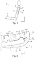
- figure 1 shows schematically a vehicle seat 1 for a vehicle, in particular for a motor vehicle.
- the representation of the vehicle seat 1 in 1 is both for an embodiment, shown in figure 2 , As well as for three modifications of the embodiment shown in the Figures 3 to 5 , applicable.
- a longitudinal direction x When the vehicle seat 1 is installed in the vehicle, it runs largely horizontally and preferably parallel to a longitudinal direction of the vehicle, which corresponds to the usual direction of travel of the vehicle.
- a transverse direction y running perpendicularly to the longitudinal direction x is likewise aligned horizontally in the vehicle and runs parallel to a vehicle transverse direction.
- a vertical direction z runs perpendicular to the longitudinal direction x and perpendicular to the transverse direction y. In the case of a vehicle seat 1 installed in the vehicle, the vertical direction z runs parallel to the vertical axis of the vehicle.
- the position and direction information used such as front, rear, up and down, relates to a viewing direction of an occupant seated in the vehicle seat 1 in a normal seated position, with the vehicle seat 1 installed in the vehicle in a usage position suitable for passenger transport with an upright backrest 5 and, as usual, is aligned in the direction of travel.
- the vehicle seat 1 according to the invention can also be installed in a different orientation, for example transversely to the direction of travel.
- the vehicle seat 1 has a seat part 3 and the backrest 5 .
- An airbag device 8 is arranged in a cavity 7 in the backrest 5 .
- the airbag device 8 comprises a gas bag which, in the event of an accident, can deploy laterally (mainly parallel to the transverse direction y) in the direction of an adjacent vehicle seat or in the direction of a vehicle structure to protect a passenger seated in the vehicle seat 1 .
- figure 2 shows a section through a backrest 5 of a vehicle seat 1 according to the invention according to an embodiment.
- the backrest 5 has a 2 supporting backrest structure, not shown, a foam part 10 and an in 2 seat cover not shown.
- the foam part 10 has a front side 12 facing the occupant of the vehicle seat 1 and a rear side 14 facing away from the occupant.
- the cavity 7 accommodates the backrest structure, not shown in the figures, and the airbag device 8 .
- the cavity 7 is in the foam part 10 intended.
- the foam part 10 In an outer area of the cavity 7, the foam part 10 has a U-shaped cross section with a first flange 18, a web 20 and a second flange 22.
- the first flange 18 is an area of the foam part 10 facing the occupant and runs predominantly parallel to the transverse direction y.
- the first flange 18 transitions into the web 20 in the area of an outside of the vehicle seat 1 .
- the web 20 runs predominantly parallel to the longitudinal direction x.
- the web 20 merges into the second flange 22 .
- the second flange 22 is a region of the foam part 10 facing away from the occupant and runs predominantly parallel to the transverse direction y.
- the second flange 22 is sword-shaped and oriented toward a seat center of the vehicle seat 1 .
- the cavity 7 is open towards the center of the seat.
- a predetermined tear point 24 is formed in the web 20 of the foam part 10 that delimits the cavity 7 .
- the predetermined tear point 24 is designed as a notch in the foam part 10, which extends from the cavity 7 in the direction of the outside of the vehicle seat 1, in the present case predominantly in the transverse direction y.
- the predetermined crack point 24 runs through the web 20 only partially.
- the predetermined tear point 24 preferably extends in the vertical direction z over at least the entire height of the gas bag, in particular over the entire height of the cavity 7.
- the web 20 of the foam part 10 tears in the direction specified by the predetermined tear point 24 completely in such a way that the airbag (possibly after severing a tear seam in the seat cover) can emerge from the vehicle seat 1 and assume a protective position for the occupants.
- the foam part 10 is at least partially reinforced in the area of the airbag device 8 by a largely flat reinforcement layer arrangement 30, so that the foam part 10 can only tear in the event of an unfolding airbag, starting from the predetermined tear point 24 and only in a predetermined direction.
- the reinforcement layer arrangement 30 in the present case comprises a first reinforcement layer 32 and a second reinforcement layer 34, which in the present case are each formed as a separate, three-dimensionally shaped fleece.
- an outer end region 32.1 of the first reinforcement layer 32 is foamed into the web 20 of the foam part 10.
- the outer end area 32.1 runs parallel to the predetermined tear point 24, but penetrates deeper towards the outside of the seat into the web 20 than the predetermined tear point 24.
- the remaining area of the first reinforcement layer 32 forms a separating layer between the first flange 18 and the cavity 7 and runs out from the outer end area 32.1 in the direction of the center of the seat and ends in an inner end area 32.2.
- an outer end region 34.1 of the second reinforcement layer 34 is foamed into the web 20 of the foam part 10.
- An outer end area 34.1 runs along the predetermined tear point 24 and ends bluntly on the first reinforcement layer 32.
- the remaining area of the second reinforcement layer 34 forms a separating layer between the web 20 and the cavity 7 and, starting from the outer end area 34.1, runs predominantly parallel to the longitudinal direction x and ends in an inner end area 34.2.
- the first modification of the exemplary embodiment shown corresponds to the exemplary embodiment, with the exception of the differences described below, which is why components that are the same or have the same effect have the same reference symbols.
- a second reinforcement layer 134 is formed differently.
- the second reinforcement layer 134 is opposite to the second reinforcement layer 34 of FIG 2 illustrated embodiment viewed in the transverse direction y larger.
- an outer end region 134.1 of the second reinforcement layer 134 is foamed into the web 20 of the foam part 10.
- the outer end region 134.1 runs parallel to the predetermined tear point 24, but penetrates deeper into the web 20 towards the outside of the seat than the predetermined tear point 24.
- the outer End area 134.1 penetrates approximately as deep into the web 20 as an outer end area 32.1 of a first reinforcement layer 32.
- the remaining area of the second reinforcement layer 134 forms a separating layer between the second flange 22 and the cavity 7 and runs from the outer end area 134.1 in the direction the center of the seat and ends in an inner end area 134.2.
- one inside figure 4 illustrated second modification of the embodiment corresponds to the differences described below in figure 2 illustrated embodiment, which is why the same or equivalent components have the same reference numerals.
- a second reinforcement layer 234 is formed differently.
- the second reinforcement layer 234 is opposite to the second reinforcement layer 34 of FIG figure 2 illustrated embodiment viewed in the transverse direction y smaller.
- a tear course 236 is also shown, which results in the event of an accident through the unfolding airbag, starting from a predetermined tear point 24 .
- an outer end region 234.1 of the second reinforcement layer 234 meets the predetermined tear point 24 approximately perpendicularly, in particular perpendicularly.
- the second reinforcement layer 234 runs approximately linearly and ends in an inner end region 234.2.
- the outer end area 234.1 is preferably slightly spaced apart from the first reinforcement layer 32.
- one inside figure 5 shown third modification of the embodiment corresponds to the differences described below in figure 2 illustrated embodiment, which is why the same or equivalent components have the same reference numerals.
- a second reinforcement layer 334 is formed differently.
- a crack path 336 is also shown schematically, which results in the event of an accident through the unfolding airbag, starting from a predetermined crack point 24 .
- the second reinforcement layer 334 is opposite to the second reinforcement layer 34 of FIG figure 2 1 of the second reinforcement layer 334 runs exclusively parallel to a predetermined tear point 24 without contacting the first reinforcement layer 32.
- a distance between the outer end region 334.1 and the first reinforcement layer 32 corresponds approximately to the width of the predetermined tear point 24 in the longitudinal direction x.
Landscapes
- Engineering & Computer Science (AREA)
- Mechanical Engineering (AREA)
- Aviation & Aerospace Engineering (AREA)
- Transportation (AREA)
- Manufacturing & Machinery (AREA)
- Air Bags (AREA)
- Seats For Vehicles (AREA)
Claims (9)
- Siège de véhicule (1) avec une partie d'assise (3) et un dossier (5), le dossier (5) présentant une partie en mousse (10) avec une cavité (7) pour recevoir au moins partiellement un dispositif d'airbag (8), la partie en mousse (10) étant revêtue au moins partiellement d'un agencement de couches de renforcement (30) dans la zone de la cavité (7), dans lequel, dans le cas d'un sac de gaz qui se déploie du dispositif d'airbag (8), l'agencement de couches de renforcement (30) guide le sac de gaz qui se déploie vers un point destiné à la rupture (24) de la partie en mousse (10), et l'agencement de couches de renforcement (30) présente une première couche de renforcement (32) et une deuxième couche de renforcement (34, 134, 234, 334),
caractérisé en ce que
la partie en mousse (10) présente une première bride (18), une deuxième bride (22) et une traverse (20) reliant la première bride (18) à la deuxième bride (22), qui délimitent la cavité (7), et une zone d'extrémité extérieure (32.1) de la première couche de renforcement (32) et/ou une zone d'extrémité extérieure (34.1, 134.1, 234.1, 334.1) de la deuxième couche de renforcement (34, 134, 234, 334) est/sont moussées dans la traverse (20). - Siège de véhicule (1) selon la revendication 1, caractérisé en ce que le dispositif d'airbag (8) est un dispositif d'airbag de type Far-Side.
- Siège de véhicule (1) selon l'une quelconque des revendications 1 ou 2, caractérisé en ce que la zone d'extrémité extérieure (32.1) de la première couche de renforcement (32) et la zone d'extrémité extérieure (334.1) de la deuxième couche de renforcement (334) reçoivent entre elles le point destiné à la rupture (24).
- Siège de véhicule (1) selon la revendication 3, caractérisé en ce que le point destiné à la rupture (24) est réalisé sous la forme d'une encoche dans la partie en mousse (10).
- Siège de véhicule (1) selon l'une quelconque des revendications 1 à 4, caractérisé en ce que la traverse (20) s'étend principalement parallèlement à un plan généré par une direction longitudinale (x) et une direction verticale (z).
- Siège de véhicule (1) selon l'une quelconque des revendications 1 à 5, caractérisé en ce que, dans la zone du point destiné à la rupture (24) de la partie en mousse (10), la zone d'extrémité extérieure (34.1) de la deuxième couche de renforcement (34) est orientée approximativement perpendiculairement à la zone d'extrémité extérieure (32.1) de la première couche de renforcement (32).
- Siège de véhicule (1) selon l'une quelconque des revendications 1 à 5, caractérisé en ce que, dans la zone du point destiné à la rupture (24) de la partie en mousse (10), la zone d'extrémité extérieure (134.1, 234.1, 334.1) de la deuxième couche de renforcement (134, 234, 334) s'étend approximativement parallèlement à la zone d'extrémité extérieure (32.1) de la première couche de renforcement (32).
- Siège de véhicule (1) selon l'une quelconque des revendications 1 à 7, caractérisé en ce qu'au moins une couche de renforcement (32, 34, 134, 234, 334) de l'agencement de couches de renforcement (30) est fabriquée à partir d'un tissu.
- Siège de véhicule (1) selon l'une quelconque des revendications 1 à 8, caractérisé en ce qu'au moins une couche de renforcement (32, 34, 134, 234, 334) de l'agencement de couches de renforcement (30) est fabriquée à partir d'une matière plastique.
Applications Claiming Priority (3)
| Application Number | Priority Date | Filing Date | Title |
|---|---|---|---|
| DE102018131810 | 2018-12-11 | ||
| DE102018133243 | 2018-12-20 | ||
| PCT/EP2019/084546 WO2020120526A1 (fr) | 2018-12-11 | 2019-12-11 | Siège de véhicule |
Publications (2)
| Publication Number | Publication Date |
|---|---|
| EP3894272A1 EP3894272A1 (fr) | 2021-10-20 |
| EP3894272B1 true EP3894272B1 (fr) | 2022-10-26 |
Family
ID=69105767
Family Applications (1)
| Application Number | Title | Priority Date | Filing Date |
|---|---|---|---|
| EP19831994.9A Active EP3894272B1 (fr) | 2018-12-11 | 2019-12-11 | Siège de véhicule |
Country Status (4)
| Country | Link |
|---|---|
| US (1) | US11541835B2 (fr) |
| EP (1) | EP3894272B1 (fr) |
| CN (1) | CN113226844B (fr) |
| WO (1) | WO2020120526A1 (fr) |
Cited By (1)
| Publication number | Priority date | Publication date | Assignee | Title |
|---|---|---|---|---|
| WO2026046852A1 (fr) * | 2024-08-26 | 2026-03-05 | Volkswagen Aktiengesellschaft | Siège de véhicule ayant un coussin de sécurité gonflable et véhicule à moteur ayant un siège de véhicule de ce type |
Families Citing this family (2)
| Publication number | Priority date | Publication date | Assignee | Title |
|---|---|---|---|---|
| CN114683984B (zh) * | 2022-03-31 | 2023-11-21 | 重庆长安汽车股份有限公司 | 一种具有侧气囊的汽车座椅靠背和汽车 |
| US12466297B1 (en) | 2024-07-26 | 2025-11-11 | Toyota Motor Engineering & Manufacturing North America, Inc. | Removable trim cover with headrest guide |
Family Cites Families (23)
| Publication number | Priority date | Publication date | Assignee | Title |
|---|---|---|---|---|
| EP0768215B1 (fr) | 1995-10-11 | 2002-11-20 | Toyota Jidosha Kabushiki Kaisha | Structure de siège comportant un système à sac gonflable pour choc latéral |
| DE19603106A1 (de) | 1996-01-29 | 1997-07-31 | Daimler Benz Ag | Fahrzeug mit zwei nebeneinander angeordneten Einzelsitzen mit Seiten-Airbags |
| US6055151A (en) | 1997-03-06 | 2000-04-25 | Sarnoff Corp | Multilayer ceramic circuit boards including embedded components |
| US6450528B1 (en) * | 1998-10-01 | 2002-09-17 | Toyota Jidosha Kabushiki Kaisha | Vehicle seat housing an airbag device |
| FR2806685B1 (fr) * | 2000-03-22 | 2002-06-21 | Peugeot Citroen Automobiles Sa | Siege de vehicule automobile comportant un sac de securite gonflable dans une partie laterale du dossier du siege |
| DE20017919U1 (de) | 2000-10-19 | 2001-03-01 | TRW Occupant Restraint Systems GmbH & Co. KG, 73553 Alfdorf | Baugruppe bestehend aus Sitzlehne und Gassack-Modul |
| DE10052942A1 (de) | 2000-10-25 | 2002-05-16 | Takata Europa Vehicle Safety T | Sicherheitsvorrichtung für Kraftfahrzeuge |
| DE10118359B4 (de) * | 2001-04-12 | 2006-06-08 | Autoliv Development Ab | Fahrzeugsitz mit einer in seinen Sitzbezug integrierten Gassackeinrichtung |
| AU2003284328A1 (en) | 2002-10-22 | 2004-05-13 | Intier Automotive Inc. | Stow in floor automotive seat assembly |
| DE20318978U1 (de) * | 2003-12-06 | 2004-02-26 | Faurecia Autositze Gmbh & Co. Kg | Rückenlehne eines Fahrzeugsitzes |
| DE102004051663B4 (de) * | 2004-09-24 | 2008-09-11 | F.S. Fehrer Automotive Foam Gmbh | Schaumkörper zur Herstellung eines Fahrzeugsitzes mit Airbagmodul |
| DE102009016887A1 (de) * | 2009-04-08 | 2010-10-14 | GM Global Technology Operations, Inc., Detroit | Fahrzeug mit einer Seitenlehne zur Integration eines Airbagmoduls |
| EP2612794A4 (fr) * | 2011-10-25 | 2015-03-25 | Toyota Motor Co Ltd | Siège de véhicule et ressort de dossier de siège en résine |
| JP5690289B2 (ja) * | 2012-01-25 | 2015-03-25 | 日本発條株式会社 | 車両用シート、及び力布の縫製方法 |
| JP5966791B2 (ja) * | 2012-09-13 | 2016-08-10 | トヨタ紡織株式会社 | サイドエアバッグを備えた車両用シートの製造方法 |
| DE102013203582B4 (de) | 2013-03-01 | 2017-06-22 | Adient Luxembourg Holding S.à.r.l. | Vorrichtung und Verfahren zur Herstellung eines Schaumstoffbauteiles |
| JP6179469B2 (ja) | 2014-06-23 | 2017-08-16 | トヨタ自動車株式会社 | ファーサイドエアバッグ装置 |
| EP2979933B1 (fr) | 2014-07-29 | 2018-06-20 | Toyoda Gosei Co., Ltd. | Appareil de coussin de sécurité gonflable d'extrémité latérale |
| DE102016200080A1 (de) * | 2015-01-14 | 2016-07-14 | Ford Global Technologies, Llc | Fahrzeugsitz mit einem in einem Sitzteil angeordneten Airbagmodul |
| JP6299704B2 (ja) * | 2015-08-06 | 2018-03-28 | トヨタ自動車株式会社 | 車両用シート |
| DE102017115254B4 (de) * | 2016-07-18 | 2023-10-26 | Hyundai Dymos Incorporated | Fahrzeugsitz mit Seitenairbag |
| DE102018208562A1 (de) * | 2018-05-30 | 2019-12-05 | Bayerische Motoren Werke Aktiengesellschaft | Kraftfahrzeug |
| DE102018124926A1 (de) * | 2018-10-09 | 2020-04-09 | Bayerische Motoren Werke Aktiengesellschaft | Fahrzeugsitz |
-
2019
- 2019-12-11 CN CN201980081220.2A patent/CN113226844B/zh active Active
- 2019-12-11 EP EP19831994.9A patent/EP3894272B1/fr active Active
- 2019-12-11 WO PCT/EP2019/084546 patent/WO2020120526A1/fr not_active Ceased
- 2019-12-11 US US17/312,418 patent/US11541835B2/en active Active
Cited By (1)
| Publication number | Priority date | Publication date | Assignee | Title |
|---|---|---|---|---|
| WO2026046852A1 (fr) * | 2024-08-26 | 2026-03-05 | Volkswagen Aktiengesellschaft | Siège de véhicule ayant un coussin de sécurité gonflable et véhicule à moteur ayant un siège de véhicule de ce type |
Also Published As
| Publication number | Publication date |
|---|---|
| WO2020120526A1 (fr) | 2020-06-18 |
| US11541835B2 (en) | 2023-01-03 |
| EP3894272A1 (fr) | 2021-10-20 |
| CN113226844B (zh) | 2023-05-30 |
| US20220017034A1 (en) | 2022-01-20 |
| CN113226844A (zh) | 2021-08-06 |
Similar Documents
| Publication | Publication Date | Title |
|---|---|---|
| DE19950702B4 (de) | Kraftfahrzeugsitz | |
| DE102018114736A1 (de) | Dachmontierter abschottender Airbag | |
| DE112014004246T5 (de) | Seitliche Vorhangairbag-Vorrichtung für ein Fahrzeug mit einer Frontalschutzfunktion | |
| DE10043290C1 (de) | Vorrichtung zum Schutz der Insassen eines Fahrzeuges bei einem Aufprall des Fahrzeuges auf ein Hindernis | |
| DE102008049505B4 (de) | Airbaganordnung für einen Fahrzeugsitz sowie Fahrzeugsitz mit der Airbaganordnung | |
| EP3894272B1 (fr) | Siège de véhicule | |
| DE102017202256B4 (de) | Fahrzeugsitzteil | |
| WO2020020827A1 (fr) | Système de retenue de passagers de véhicule comprenant un coussin gonflable de sécurité supplémentaire | |
| DE102014004185A1 (de) | Insassenschutzvorrichtung für ein Fahrzeug und Fahrzeug | |
| DE102014222658B4 (de) | Seitenvorhang-airbag für fahrzeug mit aufblasbarer erweiterung | |
| DE102018202417A1 (de) | Fahrzeuginsassen-Rückhaltesystem | |
| DE10063473B4 (de) | Dachholm-Verkleidung für aufblasbares Rückhaltesystem | |
| DE102017209417A1 (de) | Fahrzeuginsassen-Schutzvorrichtung und Fahrzeug mit einer solchen | |
| DE4204280B4 (de) | Airbagbestückter Seitenschutz für einen Kraftfahrzeuginsassen | |
| DE102018207834A1 (de) | Selbststabilisierendes Airbagsystem | |
| EP2942242B1 (fr) | Système d'airbag de tête pour véhicule et véhicule doté de celui-ci | |
| DE102019109071A1 (de) | Dachmontierter stützairbag für einen sitz | |
| DE102016209584B4 (de) | Fahrzeugsitzanordnung für ein Kraftfahrzeug | |
| DE102018200650A1 (de) | Kraftfahrzeug mit Kopf-/Schulter-Airbags | |
| WO2019228735A1 (fr) | Véhicule automobile | |
| EP3045355A1 (fr) | Siège de véhicule comprenant un module de airbag qui est disposé dans une partie de siége | |
| DE202006020577U1 (de) | Baugruppe mit einer Instrumententafel für Kraftfahrzeuge und einem Kniegassack | |
| EP3481678B1 (fr) | Airbag, en particulier pour un système d'airbag rideau latéral, système de sécurité pour véhicule comprenant un tel airbag, et véhicule muni d'un tel airbag ou système de sécurité | |
| DE202024103141U1 (de) | Airbagsystem für ein Fahrzeug | |
| DE202022104798U1 (de) | Dachairbag für ein Fahrzeug |
Legal Events
| Date | Code | Title | Description |
|---|---|---|---|
| STAA | Information on the status of an ep patent application or granted ep patent |
Free format text: STATUS: UNKNOWN |
|
| STAA | Information on the status of an ep patent application or granted ep patent |
Free format text: STATUS: THE INTERNATIONAL PUBLICATION HAS BEEN MADE |
|
| PUAI | Public reference made under article 153(3) epc to a published international application that has entered the european phase |
Free format text: ORIGINAL CODE: 0009012 |
|
| STAA | Information on the status of an ep patent application or granted ep patent |
Free format text: STATUS: REQUEST FOR EXAMINATION WAS MADE |
|
| 17P | Request for examination filed |
Effective date: 20210712 |
|
| AK | Designated contracting states |
Kind code of ref document: A1 Designated state(s): AL AT BE BG CH CY CZ DE DK EE ES FI FR GB GR HR HU IE IS IT LI LT LU LV MC MK MT NL NO PL PT RO RS SE SI SK SM TR |
|
| DAV | Request for validation of the european patent (deleted) | ||
| DAX | Request for extension of the european patent (deleted) | ||
| RAP1 | Party data changed (applicant data changed or rights of an application transferred) |
Owner name: ADIENT US LLC |
|
| GRAP | Despatch of communication of intention to grant a patent |
Free format text: ORIGINAL CODE: EPIDOSNIGR1 |
|
| STAA | Information on the status of an ep patent application or granted ep patent |
Free format text: STATUS: GRANT OF PATENT IS INTENDED |
|
| INTG | Intention to grant announced |
Effective date: 20220722 |
|
| GRAS | Grant fee paid |
Free format text: ORIGINAL CODE: EPIDOSNIGR3 |
|
| GRAA | (expected) grant |
Free format text: ORIGINAL CODE: 0009210 |
|
| STAA | Information on the status of an ep patent application or granted ep patent |
Free format text: STATUS: THE PATENT HAS BEEN GRANTED |
|
| AK | Designated contracting states |
Kind code of ref document: B1 Designated state(s): AL AT BE BG CH CY CZ DE DK EE ES FI FR GB GR HR HU IE IS IT LI LT LU LV MC MK MT NL NO PL PT RO RS SE SI SK SM TR |
|
| REG | Reference to a national code |
Ref country code: GB Ref legal event code: FG4D Free format text: NOT ENGLISH |
|
| REG | Reference to a national code |
Ref country code: CH Ref legal event code: EP |
|
| REG | Reference to a national code |
Ref country code: DE Ref legal event code: R096 Ref document number: 502019006078 Country of ref document: DE |
|
| REG | Reference to a national code |
Ref country code: AT Ref legal event code: REF Ref document number: 1526818 Country of ref document: AT Kind code of ref document: T Effective date: 20221115 |
|
| REG | Reference to a national code |
Ref country code: IE Ref legal event code: FG4D Free format text: LANGUAGE OF EP DOCUMENT: GERMAN |
|
| REG | Reference to a national code |
Ref country code: LT Ref legal event code: MG9D |
|
| REG | Reference to a national code |
Ref country code: NL Ref legal event code: MP Effective date: 20221026 |
|
| PG25 | Lapsed in a contracting state [announced via postgrant information from national office to epo] |
Ref country code: NL Free format text: LAPSE BECAUSE OF FAILURE TO SUBMIT A TRANSLATION OF THE DESCRIPTION OR TO PAY THE FEE WITHIN THE PRESCRIBED TIME-LIMIT Effective date: 20221026 |
|
| PG25 | Lapsed in a contracting state [announced via postgrant information from national office to epo] |
Ref country code: SE Free format text: LAPSE BECAUSE OF FAILURE TO SUBMIT A TRANSLATION OF THE DESCRIPTION OR TO PAY THE FEE WITHIN THE PRESCRIBED TIME-LIMIT Effective date: 20221026 Ref country code: PT Free format text: LAPSE BECAUSE OF FAILURE TO SUBMIT A TRANSLATION OF THE DESCRIPTION OR TO PAY THE FEE WITHIN THE PRESCRIBED TIME-LIMIT Effective date: 20230227 Ref country code: NO Free format text: LAPSE BECAUSE OF FAILURE TO SUBMIT A TRANSLATION OF THE DESCRIPTION OR TO PAY THE FEE WITHIN THE PRESCRIBED TIME-LIMIT Effective date: 20230126 Ref country code: LT Free format text: LAPSE BECAUSE OF FAILURE TO SUBMIT A TRANSLATION OF THE DESCRIPTION OR TO PAY THE FEE WITHIN THE PRESCRIBED TIME-LIMIT Effective date: 20221026 Ref country code: FI Free format text: LAPSE BECAUSE OF FAILURE TO SUBMIT A TRANSLATION OF THE DESCRIPTION OR TO PAY THE FEE WITHIN THE PRESCRIBED TIME-LIMIT Effective date: 20221026 Ref country code: ES Free format text: LAPSE BECAUSE OF FAILURE TO SUBMIT A TRANSLATION OF THE DESCRIPTION OR TO PAY THE FEE WITHIN THE PRESCRIBED TIME-LIMIT Effective date: 20221026 |
|
| PG25 | Lapsed in a contracting state [announced via postgrant information from national office to epo] |
Ref country code: RS Free format text: LAPSE BECAUSE OF FAILURE TO SUBMIT A TRANSLATION OF THE DESCRIPTION OR TO PAY THE FEE WITHIN THE PRESCRIBED TIME-LIMIT Effective date: 20221026 Ref country code: PL Free format text: LAPSE BECAUSE OF FAILURE TO SUBMIT A TRANSLATION OF THE DESCRIPTION OR TO PAY THE FEE WITHIN THE PRESCRIBED TIME-LIMIT Effective date: 20221026 Ref country code: LV Free format text: LAPSE BECAUSE OF FAILURE TO SUBMIT A TRANSLATION OF THE DESCRIPTION OR TO PAY THE FEE WITHIN THE PRESCRIBED TIME-LIMIT Effective date: 20221026 Ref country code: IS Free format text: LAPSE BECAUSE OF FAILURE TO SUBMIT A TRANSLATION OF THE DESCRIPTION OR TO PAY THE FEE WITHIN THE PRESCRIBED TIME-LIMIT Effective date: 20230226 Ref country code: HR Free format text: LAPSE BECAUSE OF FAILURE TO SUBMIT A TRANSLATION OF THE DESCRIPTION OR TO PAY THE FEE WITHIN THE PRESCRIBED TIME-LIMIT Effective date: 20221026 Ref country code: GR Free format text: LAPSE BECAUSE OF FAILURE TO SUBMIT A TRANSLATION OF THE DESCRIPTION OR TO PAY THE FEE WITHIN THE PRESCRIBED TIME-LIMIT Effective date: 20230127 |
|
| REG | Reference to a national code |
Ref country code: DE Ref legal event code: R097 Ref document number: 502019006078 Country of ref document: DE |
|
| PG25 | Lapsed in a contracting state [announced via postgrant information from national office to epo] |
Ref country code: SM Free format text: LAPSE BECAUSE OF FAILURE TO SUBMIT A TRANSLATION OF THE DESCRIPTION OR TO PAY THE FEE WITHIN THE PRESCRIBED TIME-LIMIT Effective date: 20221026 Ref country code: RO Free format text: LAPSE BECAUSE OF FAILURE TO SUBMIT A TRANSLATION OF THE DESCRIPTION OR TO PAY THE FEE WITHIN THE PRESCRIBED TIME-LIMIT Effective date: 20221026 Ref country code: EE Free format text: LAPSE BECAUSE OF FAILURE TO SUBMIT A TRANSLATION OF THE DESCRIPTION OR TO PAY THE FEE WITHIN THE PRESCRIBED TIME-LIMIT Effective date: 20221026 Ref country code: DK Free format text: LAPSE BECAUSE OF FAILURE TO SUBMIT A TRANSLATION OF THE DESCRIPTION OR TO PAY THE FEE WITHIN THE PRESCRIBED TIME-LIMIT Effective date: 20221026 Ref country code: CZ Free format text: LAPSE BECAUSE OF FAILURE TO SUBMIT A TRANSLATION OF THE DESCRIPTION OR TO PAY THE FEE WITHIN THE PRESCRIBED TIME-LIMIT Effective date: 20221026 |
|
| REG | Reference to a national code |
Ref country code: CH Ref legal event code: PL |
|
| REG | Reference to a national code |
Ref country code: BE Ref legal event code: MM Effective date: 20221231 |
|
| PG25 | Lapsed in a contracting state [announced via postgrant information from national office to epo] |
Ref country code: SK Free format text: LAPSE BECAUSE OF FAILURE TO SUBMIT A TRANSLATION OF THE DESCRIPTION OR TO PAY THE FEE WITHIN THE PRESCRIBED TIME-LIMIT Effective date: 20221026 Ref country code: LU Free format text: LAPSE BECAUSE OF NON-PAYMENT OF DUE FEES Effective date: 20221211 Ref country code: AL Free format text: LAPSE BECAUSE OF FAILURE TO SUBMIT A TRANSLATION OF THE DESCRIPTION OR TO PAY THE FEE WITHIN THE PRESCRIBED TIME-LIMIT Effective date: 20221026 |
|
| PLBE | No opposition filed within time limit |
Free format text: ORIGINAL CODE: 0009261 |
|
| STAA | Information on the status of an ep patent application or granted ep patent |
Free format text: STATUS: NO OPPOSITION FILED WITHIN TIME LIMIT |
|
| 26N | No opposition filed |
Effective date: 20230727 |
|
| PG25 | Lapsed in a contracting state [announced via postgrant information from national office to epo] |
Ref country code: LI Free format text: LAPSE BECAUSE OF NON-PAYMENT OF DUE FEES Effective date: 20221231 Ref country code: IE Free format text: LAPSE BECAUSE OF NON-PAYMENT OF DUE FEES Effective date: 20221211 Ref country code: CH Free format text: LAPSE BECAUSE OF NON-PAYMENT OF DUE FEES Effective date: 20221231 |
|
| PG25 | Lapsed in a contracting state [announced via postgrant information from national office to epo] |
Ref country code: SI Free format text: LAPSE BECAUSE OF FAILURE TO SUBMIT A TRANSLATION OF THE DESCRIPTION OR TO PAY THE FEE WITHIN THE PRESCRIBED TIME-LIMIT Effective date: 20221026 Ref country code: BE Free format text: LAPSE BECAUSE OF NON-PAYMENT OF DUE FEES Effective date: 20221231 |
|
| PG25 | Lapsed in a contracting state [announced via postgrant information from national office to epo] |
Ref country code: CY Free format text: LAPSE BECAUSE OF FAILURE TO SUBMIT A TRANSLATION OF THE DESCRIPTION OR TO PAY THE FEE WITHIN THE PRESCRIBED TIME-LIMIT Effective date: 20221026 |
|
| PG25 | Lapsed in a contracting state [announced via postgrant information from national office to epo] |
Ref country code: MK Free format text: LAPSE BECAUSE OF FAILURE TO SUBMIT A TRANSLATION OF THE DESCRIPTION OR TO PAY THE FEE WITHIN THE PRESCRIBED TIME-LIMIT Effective date: 20221026 Ref country code: IT Free format text: LAPSE BECAUSE OF FAILURE TO SUBMIT A TRANSLATION OF THE DESCRIPTION OR TO PAY THE FEE WITHIN THE PRESCRIBED TIME-LIMIT Effective date: 20221026 Ref country code: HU Free format text: LAPSE BECAUSE OF FAILURE TO SUBMIT A TRANSLATION OF THE DESCRIPTION OR TO PAY THE FEE WITHIN THE PRESCRIBED TIME-LIMIT; INVALID AB INITIO Effective date: 20191211 |
|
| PG25 | Lapsed in a contracting state [announced via postgrant information from national office to epo] |
Ref country code: MC Free format text: LAPSE BECAUSE OF FAILURE TO SUBMIT A TRANSLATION OF THE DESCRIPTION OR TO PAY THE FEE WITHIN THE PRESCRIBED TIME-LIMIT Effective date: 20221026 |
|
| PG25 | Lapsed in a contracting state [announced via postgrant information from national office to epo] |
Ref country code: TR Free format text: LAPSE BECAUSE OF FAILURE TO SUBMIT A TRANSLATION OF THE DESCRIPTION OR TO PAY THE FEE WITHIN THE PRESCRIBED TIME-LIMIT Effective date: 20221026 Ref country code: MC Free format text: LAPSE BECAUSE OF FAILURE TO SUBMIT A TRANSLATION OF THE DESCRIPTION OR TO PAY THE FEE WITHIN THE PRESCRIBED TIME-LIMIT Effective date: 20221026 |
|
| PG25 | Lapsed in a contracting state [announced via postgrant information from national office to epo] |
Ref country code: BG Free format text: LAPSE BECAUSE OF FAILURE TO SUBMIT A TRANSLATION OF THE DESCRIPTION OR TO PAY THE FEE WITHIN THE PRESCRIBED TIME-LIMIT Effective date: 20221026 |
|
| GBPC | Gb: european patent ceased through non-payment of renewal fee |
Effective date: 20231211 |
|
| PG25 | Lapsed in a contracting state [announced via postgrant information from national office to epo] |
Ref country code: MT Free format text: LAPSE BECAUSE OF FAILURE TO SUBMIT A TRANSLATION OF THE DESCRIPTION OR TO PAY THE FEE WITHIN THE PRESCRIBED TIME-LIMIT Effective date: 20221026 |
|
| PG25 | Lapsed in a contracting state [announced via postgrant information from national office to epo] |
Ref country code: GB Free format text: LAPSE BECAUSE OF NON-PAYMENT OF DUE FEES Effective date: 20231211 |
|
| PG25 | Lapsed in a contracting state [announced via postgrant information from national office to epo] |
Ref country code: GB Free format text: LAPSE BECAUSE OF NON-PAYMENT OF DUE FEES Effective date: 20231211 |
|
| REG | Reference to a national code |
Ref country code: DE Ref legal event code: R082 Ref document number: 502019006078 Country of ref document: DE Representative=s name: LIEDTKE & PARTNER PATENTANWAELTE, DE |
|
| PGFP | Annual fee paid to national office [announced via postgrant information from national office to epo] |
Ref country code: FR Payment date: 20251226 Year of fee payment: 7 |
|
| REG | Reference to a national code |
Ref country code: AT Ref legal event code: MM01 Ref document number: 1526818 Country of ref document: AT Kind code of ref document: T Effective date: 20241211 |
|
| PGFP | Annual fee paid to national office [announced via postgrant information from national office to epo] |
Ref country code: DE Payment date: 20251229 Year of fee payment: 7 |
|
| PG25 | Lapsed in a contracting state [announced via postgrant information from national office to epo] |
Ref country code: AT Free format text: LAPSE BECAUSE OF NON-PAYMENT OF DUE FEES Effective date: 20241211 |
|
| PGFP | Annual fee paid to national office [announced via postgrant information from national office to epo] |
Ref country code: AT Payment date: 20260410 Year of fee payment: 5 |