EP3894332B1 - Bouchon pour distribution de liquides à partir d'un récipient - Google Patents
Bouchon pour distribution de liquides à partir d'un récipient Download PDFInfo
- Publication number
- EP3894332B1 EP3894332B1 EP18942732.1A EP18942732A EP3894332B1 EP 3894332 B1 EP3894332 B1 EP 3894332B1 EP 18942732 A EP18942732 A EP 18942732A EP 3894332 B1 EP3894332 B1 EP 3894332B1
- Authority
- EP
- European Patent Office
- Prior art keywords
- container
- cap
- outer member
- inner member
- liquid
- Prior art date
- Legal status (The legal status is an assumption and is not a legal conclusion. Google has not performed a legal analysis and makes no representation as to the accuracy of the status listed.)
- Active
Links
Images


Classifications
-
- B—PERFORMING OPERATIONS; TRANSPORTING
- B65—CONVEYING; PACKING; STORING; HANDLING THIN OR FILAMENTARY MATERIAL
- B65D—CONTAINERS FOR STORAGE OR TRANSPORT OF ARTICLES OR MATERIALS, e.g. BAGS, BARRELS, BOTTLES, BOXES, CANS, CARTONS, CRATES, DRUMS, JARS, TANKS, HOPPERS, FORWARDING CONTAINERS; ACCESSORIES, CLOSURES, OR FITTINGS THEREFOR; PACKAGING ELEMENTS; PACKAGES
- B65D47/00—Closures with filling and discharging, or with discharging, devices
- B65D47/04—Closures with discharging devices other than pumps
- B65D47/043—Closures with discharging devices other than pumps with pouring baffles, e.g. for controlling the flow
-
- B—PERFORMING OPERATIONS; TRANSPORTING
- B65—CONVEYING; PACKING; STORING; HANDLING THIN OR FILAMENTARY MATERIAL
- B65D—CONTAINERS FOR STORAGE OR TRANSPORT OF ARTICLES OR MATERIALS, e.g. BAGS, BARRELS, BOTTLES, BOXES, CANS, CARTONS, CRATES, DRUMS, JARS, TANKS, HOPPERS, FORWARDING CONTAINERS; ACCESSORIES, CLOSURES, OR FITTINGS THEREFOR; PACKAGING ELEMENTS; PACKAGES
- B65D47/00—Closures with filling and discharging, or with discharging, devices
- B65D47/04—Closures with discharging devices other than pumps
- B65D47/20—Closures with discharging devices other than pumps comprising hand-operated members for controlling discharge
- B65D47/24—Closures with discharging devices other than pumps comprising hand-operated members for controlling discharge with poppet valves or lift valves, i.e. valves opening or closing a passageway by a relative motion substantially perpendicular to the plane of the seat
-
- B—PERFORMING OPERATIONS; TRANSPORTING
- B65—CONVEYING; PACKING; STORING; HANDLING THIN OR FILAMENTARY MATERIAL
- B65D—CONTAINERS FOR STORAGE OR TRANSPORT OF ARTICLES OR MATERIALS, e.g. BAGS, BARRELS, BOTTLES, BOXES, CANS, CARTONS, CRATES, DRUMS, JARS, TANKS, HOPPERS, FORWARDING CONTAINERS; ACCESSORIES, CLOSURES, OR FITTINGS THEREFOR; PACKAGING ELEMENTS; PACKAGES
- B65D47/00—Closures with filling and discharging, or with discharging, devices
- B65D47/04—Closures with discharging devices other than pumps
- B65D47/32—Closures with discharging devices other than pumps with means for venting
-
- B—PERFORMING OPERATIONS; TRANSPORTING
- B65—CONVEYING; PACKING; STORING; HANDLING THIN OR FILAMENTARY MATERIAL
- B65D—CONTAINERS FOR STORAGE OR TRANSPORT OF ARTICLES OR MATERIALS, e.g. BAGS, BARRELS, BOTTLES, BOXES, CANS, CARTONS, CRATES, DRUMS, JARS, TANKS, HOPPERS, FORWARDING CONTAINERS; ACCESSORIES, CLOSURES, OR FITTINGS THEREFOR; PACKAGING ELEMENTS; PACKAGES
- B65D50/00—Closures with means for discouraging unauthorised opening or removal thereof, with or without indicating means, e.g. child-proof closures
- B65D50/02—Closures with means for discouraging unauthorised opening or removal thereof, with or without indicating means, e.g. child-proof closures openable or removable by the combination of plural actions
- B65D50/04—Closures with means for discouraging unauthorised opening or removal thereof, with or without indicating means, e.g. child-proof closures openable or removable by the combination of plural actions requiring the combination of simultaneous actions, e.g. depressing and turning, lifting and turning, maintaining a part and turning another one
- B65D50/041—Closures with means for discouraging unauthorised opening or removal thereof, with or without indicating means, e.g. child-proof closures openable or removable by the combination of plural actions requiring the combination of simultaneous actions, e.g. depressing and turning, lifting and turning, maintaining a part and turning another one the closure comprising nested inner and outer caps or an inner cap and an outer coaxial annular member, which can be brought into engagement to enable removal by rotation
-
- B—PERFORMING OPERATIONS; TRANSPORTING
- B65—CONVEYING; PACKING; STORING; HANDLING THIN OR FILAMENTARY MATERIAL
- B65D—CONTAINERS FOR STORAGE OR TRANSPORT OF ARTICLES OR MATERIALS, e.g. BAGS, BARRELS, BOTTLES, BOXES, CANS, CARTONS, CRATES, DRUMS, JARS, TANKS, HOPPERS, FORWARDING CONTAINERS; ACCESSORIES, CLOSURES, OR FITTINGS THEREFOR; PACKAGING ELEMENTS; PACKAGES
- B65D51/00—Closures not otherwise provided for
- B65D51/16—Closures not otherwise provided for with means for venting air or gas
- B65D51/1605—Closures not otherwise provided for with means for venting air or gas whereby the interior of the container is maintained in permanent gaseous communication with the exterior
- B65D51/1611—Closures not otherwise provided for with means for venting air or gas whereby the interior of the container is maintained in permanent gaseous communication with the exterior by means of an orifice, capillary or labyrinth passage
-
- B—PERFORMING OPERATIONS; TRANSPORTING
- B65—CONVEYING; PACKING; STORING; HANDLING THIN OR FILAMENTARY MATERIAL
- B65D—CONTAINERS FOR STORAGE OR TRANSPORT OF ARTICLES OR MATERIALS, e.g. BAGS, BARRELS, BOTTLES, BOXES, CANS, CARTONS, CRATES, DRUMS, JARS, TANKS, HOPPERS, FORWARDING CONTAINERS; ACCESSORIES, CLOSURES, OR FITTINGS THEREFOR; PACKAGING ELEMENTS; PACKAGES
- B65D51/00—Closures not otherwise provided for
- B65D51/18—Arrangements of closures with protective outer cap-like covers or of two or more co-operating closures
-
- B—PERFORMING OPERATIONS; TRANSPORTING
- B65—CONVEYING; PACKING; STORING; HANDLING THIN OR FILAMENTARY MATERIAL
- B65D—CONTAINERS FOR STORAGE OR TRANSPORT OF ARTICLES OR MATERIALS, e.g. BAGS, BARRELS, BOTTLES, BOXES, CANS, CARTONS, CRATES, DRUMS, JARS, TANKS, HOPPERS, FORWARDING CONTAINERS; ACCESSORIES, CLOSURES, OR FITTINGS THEREFOR; PACKAGING ELEMENTS; PACKAGES
- B65D2215/00—Child-proof means
- B65D2215/02—Child-proof means requiring the combination of simultaneous actions
-
- B—PERFORMING OPERATIONS; TRANSPORTING
- B65—CONVEYING; PACKING; STORING; HANDLING THIN OR FILAMENTARY MATERIAL
- B65D—CONTAINERS FOR STORAGE OR TRANSPORT OF ARTICLES OR MATERIALS, e.g. BAGS, BARRELS, BOTTLES, BOXES, CANS, CARTONS, CRATES, DRUMS, JARS, TANKS, HOPPERS, FORWARDING CONTAINERS; ACCESSORIES, CLOSURES, OR FITTINGS THEREFOR; PACKAGING ELEMENTS; PACKAGES
- B65D2251/00—Details relating to container closures
- B65D2251/0003—Two or more closures
- B65D2251/0006—Upper closure
- B65D2251/0025—Upper closure of the 47-type
-
- B—PERFORMING OPERATIONS; TRANSPORTING
- B65—CONVEYING; PACKING; STORING; HANDLING THIN OR FILAMENTARY MATERIAL
- B65D—CONTAINERS FOR STORAGE OR TRANSPORT OF ARTICLES OR MATERIALS, e.g. BAGS, BARRELS, BOTTLES, BOXES, CANS, CARTONS, CRATES, DRUMS, JARS, TANKS, HOPPERS, FORWARDING CONTAINERS; ACCESSORIES, CLOSURES, OR FITTINGS THEREFOR; PACKAGING ELEMENTS; PACKAGES
- B65D2251/00—Details relating to container closures
- B65D2251/0003—Two or more closures
- B65D2251/0068—Lower closure
- B65D2251/009—Lower closure of the 51-type
Definitions
- caps and/or closures of different shapes and sealing mechanisms used with bottles for containing a variety of fluids including, but not limited to, industrial chemicals, chemical reagents and cleaning liquids.
- fluids tend to be either highly corrosive or acidic and hence, can cause injury to persons dispensing same from a bottle, in particular, if the fluid comes into contact with the individual's eyes and/or skin during dispensing.
- Examples of known solutions of a cap and closures are disclosed in document US2017/233148 .
- Conventional caps and closures for bottles generally include a thread located on the internal side surface of the cap that engages a corresponding thread located on the external surface of the bottle neck to thereby enable the cap/closure to be fixed to the bottle neck by a twisting/rotating motion of the cap in one direction relative to the bottle, to thereby seal or "close” the bottle.
- the cap/closure is rotated/twisted in the opposite direction.
- Conventional cap/closure systems for bottles may also include a separate sealing component that is usually in the form of a disc fabricated from plastic or any type of impervious material that is heat sealed, or otherwise fixed, to the bottle opening to thereby seal the opening and avoid the risk of spillage/leaking of any fluid, particularly during packing and transport of the bottles at which times the bottles are often tilted from the upright position.
- a separate sealing component that is usually in the form of a disc fabricated from plastic or any type of impervious material that is heat sealed, or otherwise fixed, to the bottle opening to thereby seal the opening and avoid the risk of spillage/leaking of any fluid, particularly during packing and transport of the bottles at which times the bottles are often tilted from the upright position.
- caps and closures have associated problems, since such caps/closures must be fully detached during opening of the bottle and dispensing of fluid, which can lead to loss of the cap. This is problematic in instances in which only a portion of the fluid is dispensed at any given time, and under such circumstances, bottles are either maintained in an open state or some other type ad hoc sealing mechanism must be adopted to close the bottle. Clearly this is undesirable since this increases the risk of spillage/leakage, which is even more problematic in the instance of hazardous fluids and thereby presents an occupational health and safety issue.
- the dispensing of hazardous (corrosive) fluids is also problematic during instances in which large volumes of fluid are dispensed and/or in instances in which a volume of fluid has to be rapidly dispensed. This typically results in a non-uniform "glugging" action accompanied by splashing of the liquid during dispensing which is, for reasons previously discussed, an occupational health and safety issue. It is understood that the "glugging" action arises as a result of the creation of a pressure differential between the interior and exterior of the bottle as the bottle contents are dispensed. When the external pressure increases to a point above the internal pressure of the bottle, the external pressure forces air back into the bottle in an attempt to equalize the internal and external pressure, thereby simultaneously forcing fluid to rapidly flow out of the bottle. This action causes the formation of a pocket of air which results in the familiar "glug".
- puncturing the bottle is undesirable from an occupational health and safety perspective since the aperture can lead to leakage/spillage of the vessel contents, and also, present a problem in the event only a portion of the vessel contents are dispensed at any given time.
- the present invention provides a cap according to independent claim 1.
- the present invention provides a method of dispensing liquid from a container according to independent claim 9.
- the present invention provides a container assembly according to dependent claim 12.
- the present invention provides a method of manufacturing a cap according to independent claim 14.
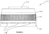
- container (100) is shown in perspective view with fitted cap (110) in accordance with an embodiment of the invention.
- Cap (110) includes two components, inner member (111) and outer member (112) that are detailed and described in Figures 2 to 5 and 6 to 9 , respectively.
- Figure 2 details inner member (111) in side view in which thread (140) located on the external surface of rim (125) is shown that engages thread (144) located on an internal surface of rim (142) of outer member (112) (shown in Figures 6 to 9 ). Accordingly, inner member (111) and outer member (112) are in threaded connection and can be connected by rotating inner member (111) relative to outer member (112) to engage threads (140) and (144).
- Figure 2 also details guide lugs (136) the function of which will be described in further detail with reference to Figures 12 to 15 in which the inner member (111) and outer member (112) of cap (110) are shown in an engaged state.
- Figure 2 further details teeth (127) located on the external periphery of rim (125) that define a ratchet and which serve to prevent rotation of inner member (111) relative to outer member (112) so as to maintain cap (110) in a closed state prior to purchase and use.
- teeth (127) and the way the ratchet defined by same will be described in further detail with reference to Figures 12 to 15 in which inner member (111) and outer member (112) of cap (110) are shown in an engaged state.
- Inner member (111) is shown in top view in Figure 3 which details teeth (127) located on the external surface of rim (125) (see Figure 2 ) and also guide lugs (136) which engage corresponding drive lugs (134) located on outer member (112).
- the purpose, function and the way in which guide lugs (136) engage drive lugs (134) will be described in further detail with reference to Figures 12 to 15 in which inner (111) and outer (112) members are shown in an engaged state.
- Figure 3 also details flexible tongues (122) that engage projection (123 - shown in Figure 8 ) located on outer member (112) and that serves to prevent the removal of outer member (112) from inner member (111) as will be further described with reference to Figures 12 to 15 .
- Figure 3 also details base portion (152) that extends radially inwardly a sufficient distance such that inner periphery (154) of base portion (152) forms part of a first seal between inner (111) and outer (112) members when outer member (112) is in a first (closed) position.
- base portion (152) and how it functions as part of a first seal will be described in further detail with reference to Figure 14 .
- Figure 4 shows a bottom view of inner member (111) in which teeth (127) are visible.
- Figure 4 also details teeth (126) located on the internal surface of rim (125) that serve as another ratchet that prevents the removal of inner member from container (100) during use.
- teeth (126) and the ratchet defined by same will be described in further detail with reference to Figures 12 to 15 that show inner (111) and outer (112) members in an engaged state.
- Figure 4 also shows internal annulus (150) that includes base portion (152) that extends radially inwardly a sufficient distance such that inner periphery (154) forms part of a first seal when it abuts the outer periphery (see Figure 15 ) of base portion (132) located on outer member (112) when outer member (112) is in a first (closed) position.
- FIG. 5 A side sectional view of inner member (111) is shown in Figure 5 in which teeth (126) and guide lugs (136) are shown.
- Figure 5 also details thread (138) located on the internal surface of rim (125) that engages a corresponding thread (not shown) located on container (100) to thereby secure inner member (111) to container (100).
- Figure 5 also details thread (140) located on the external surface of rim (125) that serves to connect inner member (111) to outer member (112).
- Figure 5 also details flexible tongue (122) used to prevent outer member (112) from being removed from inner member (111).
- Figure 5 also details internal annulus (150) which includes base portion (152) that forms part of a first seal (135 - see figure 14 )) when the inner periphery (154) of base portion (152) abuts the outer periphery (133 - see Figure 9 ) of base portion (132 - see Figure 9 ) of outer member (112) when outer member (112) is in a first (closed) position.
- outer member (112) The features of outer member (112) will now be described with reference to Figures 6 to 9 .
- Figure 6 shows a side view of outer member (112) detailing lip (113) that serves to prevent, or at least minimise, dripping of liquid during dispensing.
- Figure 6 also details knurling (114) located on the external surface of rim (142).
- "knurling” represents a textured region on any surface that may include a pattern of straight, angled or crossed lines that are rolled, pressed, stamped or otherwise introduced onto a surface that serves to provide manual grip during movement of a part.
- knurling (114) serves to provide manual grip of outer member (112) when it is moved (rotated) relative to inner member (111) in order to open the cap and allow dispensing of fluid.
- Knurling (114) also serves to provide mechanical grip when outer member (112) is engaged with inner member (111) and the assembled cap is driven onto container (100) by the use of a conventional capping chuck.
- Figure 6 further details bridges (118) that connect tamper ring (116) to rim (142) of outer member (112).
- FIG. 7 A top view of outer cap (112) is shown in Figure 7 that details knurling (114) located on rim (142). Ribs (120) arranged in a spoke arrangement are also detailed which define flow channels (121) through which liquid exits and/or air enters container (100) during dispensing. The function of ribs (120) and flow channels (121) is further described with reference to Figures 10 to 15 and also Figures 29 to 31 .
- FIG 7 also details top portion (131) and base portion (132) of central support structure (130 - shown in Figure 9 ).
- Central support structure (130) serves to support ribs (120) and also functions as part of a first seal that substantially prevents the flow of liquid when outer member (112) is in a first (closed) position.
- Central support structure also includes wall (137 - shown in Figure 9 ) that forms part of a second seal and that will be described in further detail with reference to Figure 15 .
- FIG 7 also details vent hole (124) which is an optional feature that is adopted when liquids that require continuous venting are stored in container (100).
- vent hole (124) is further described with reference to Figure 13 that shows a top view of cap (110) when in an assembled state in which inner member (111) is connected, by threaded connection, to outer member (112).
- Figure 8 shows outer member (112) in bottom view detailing teeth (128) that define a ratchet located on the internal surface of tamper ring (116). Also detailed are ribs (120) that define flow channels (121) (flow channels (121) defined by ribs (120) are more clearly illustrated in Figure 11 ). Thread (144) located on the internal surface of rim (142) is also shown in addition to vent hole (124) located on top portion (131) of central support structure (130 -shown in Figure 9 ). Also shown is base portion (132) located on central support structure (130 - shown in Figure 9 ).
- Figure 8 also details drive lugs (134) the function of which are described in detail with reference to Figures 12 to 15 that show cap (110) in an assembled state in which inner member (111) is connected, by threaded connection, to outer member (112).
- FIG. 9 A side sectional view of outer member (112) is shown in Figure 9 in which lip (113) and ribs (120) are shown. Ribs (120) are connected to central support structure (130) which includes a top portion (131) and also a base portion (132). Base portion (132) serves to form part of a first seal and thereby substantially prevents the flow of liquid when outer member (112) is in a first (closed) position.
- the function of the first seal is further described with reference to Figures 12 to 15 which detail cap (110) when in an assembled state in which inner member (111) is connected, by threaded connection, to outer member (112).
- thread (144) located on an internal surface of rim (142) of outer member (112) that serves to connect, via threaded connection, inner (111) and outer (112) members.
- Figure 9 further details drive lugs (134) the function of which are described in detail with reference to Figures 12 to 15 that show cap (110) in an assembled state in which inner member (111) is connected, by threaded connection, to outer member (112).
- Figure 10 shows outer member (112) in perspective view in which the configuration of ribs (120) in relation to lip (113) may be observed.
- ribs (120) have an upward curvature as they extend radially outward from central support structure (130) towards the outer periphery of outer member (112).
- the upward curvature of ribs (120) cause the end of ribs (120) to meet the base of lip (113) to thereby smoothly transition the surface of the ribs (120) to the surface of lip (113) and thereby provide a smooth surface over which liquid may travel during egress from the container and dispensing opening of cap (110) upon sufficient tilting of the container.
- the smooth transition of the surface of the ribs (120) to the surface of the lip (113) may assist in achieving more even flow of liquid over ribs (120) and lip (113) during dispensing of the container contents thereby avoiding, or ameliorating splashing and/or dripping of liquid.
- FIG 11 details a perspective view of the internal rib spoke arrangement of outer member (112) in which the wall of outer member (112) has been removed to more clearly illustrate the internal spoke arrangement of ribs (120) and how the configuration of ribs (120) define a plurality of flow channels (121).
- each of ribs (120) have a notched (or cut-away) section thereby defining portion (120a) that is of a narrower width dimension as compared with portion (120b).
- “narrow" portion (120a) on each of ribs (120) permits the entry of liquid into the spoked rib arrangement of outer member (112) when cap (110) is in an "open” state to thereby permit dispensing of liquid from the container through dispensing opening of cap (110).
- the "wider" portion (120b) of rib (120) is of a width dimension that is sufficient to cause the edge of rib (120) to abut the internal wall surface of cap (110) such that two adjacent spaced apart ribs (120), central support structure (130) and the internal surface of outer member (112) wall define an enclosed flow channel (121).
- the ribs (120) in combination with the internal surface of the outer member (112) wall and central support structure (130) increase the surface area of outer member (112) with which liquid comes into contact during egress from the container through cap (110).
- flow channels (121) serve to slow down the rate of liquid flow through frictional resistance as the liquid egresses from the container, especially in regions where the liquid comes into contact with the surface of ribs (120), central support structure (130) and the internal surface of outer member (112) wall.
- ribs (120) by forcing the liquid to enter one or more flow channels (121) during egress from the container through cap (110), effectively increases the contact surface area between the liquid and outer member (112) thereby slowing the rate of liquid flow and mitigating the "glugging" effect during dispensing of liquid from the container.
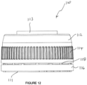
- inner member (111) and outer member (112) when the cap (110) is in an engaged state is shown in Figures 12 to 15 and, in particular, the sectional view shown in Figure 15 .
- cap (110) is shown in side view detailing outer member (112) that includes lip (113) that prevents, or at least minimises, any excess dripping of the liquid contents during dispensing.
- Outer member (112) also details knurling (114) surrounding the external surface of rim (115) of outer member (112).
- Figure 12 also shows tamper ring (116) connected to outer member (112) by a series of bridges (118) that may be broken by the manual application of a force when the cap (110) is used and opened for the first time.
- bridges (118) Upon breakage of bridges (118), outer member (112) is able to be moved (rotated) relative to inner member (111) from a first (closed) position to a second (open) position to thereby open cap (110) and enable fluid contained within container (100) (shown in Figure 1 ) fitted with cap (110) to be dispensed from container (100).
- Cap (110) is shown in top view in Figure 13 , detailing, once again, lip (112) and knurling (114) located on outer member (112).
- Outer member (112) also includes ribs (120) disposed in a spoke arrangement (refer also to Figure 11 ) which defines a plurality of flow channels (121) through which liquid passes during dispensing of the liquid from container (100) shown in Figure 1 .
- Ribs (120) serve to avoid, or at least ameliorate, any surging "glugging" of liquid as it passes and exits through cap (110) during dispensing of the contents of container (100).
- Ribs (120) serve to disrupt and retard the liquid flow rate to a point that is sufficient to avoid or at least reduce any surging "glugging" of the liquid. Ribs (120) also facilitate the entry of air back into the container during dispensing to thereby equalise the internal and external pressure with respect to the container and thereby permit and/or promote liquid flow from the container.
- a passage defining 8 channels arranged in a spoke arrangement is preferred since this provides sufficient flow area for the passage of liquid out of the container through dispensing opening of cap (110) yet also provides sufficient surface area of ribs (120) such that the flow of liquid is sufficiently retarded through frictional contact of the liquid with the surface of ribs (120) to thereby mitigate "glugging" of the liquid as it exits container (100) through dispensing opening of cap (110).
- ribs (120) that facilitate the entry of air back into the container during dispensing avoids the need to puncture the container during use so as to permit and/or promote liquid flow.
- the avoidance or mitigation of "glugging" of the liquid also results in a more controlled flow of liquid that prevents or minimises the risk of spillage of any liquid during dispensing. Both of these factors are beneficial from an occupational health and safety perspective, particularly in respect of circumstances in which hazardous, toxic and/or flammable liquids are dispensed from a container.
- Figure 13 also details flexible tongue (122) located on outer member (112) that prevents removal of outer member (112) from inner member (111) after assembly and during use in the absence of the application of excessive force, wherein flexible tongue (122) is pushed past projection (123 - shown in Figure 8 ) during assembly of inner member (111) and outer member (112).
- Outer member (112) further includes, in this embodiment, optional vent hole (124) that is useful when liquids that require continuous venting are stored within container (100).
- optional vent hole (124) that is useful when liquids that require continuous venting are stored within container (100).
- many industrial liquids and reagents stored in containers can cause the containers to expand or even explode during transportation and storage and thereby require the use of one or more vent holes which are designed to enable the container to "breathe” and thereby equalize pressure within the container preventing distortion and damage of the container.
- porous discs may be placed within vent holes (124) that enables container (100) to breathe. Such porous discs are known and readily available.
- FIG. 14 a bottom view of cap (110) is shown that details vent hole (124) located on outer member (112).
- Figure 14 also details tamper ring (116) connected to outer member (112) of which only the top portion (131) of the central support structure (130 - see Figure 15 ) of outer member (112) is visible.
- Figure 14 also details dual ratchet systems adopted with cap (110) that each serve to secure inner member (111) to container (100) and also avoids a user tampering with the contents of container (100) prior to purchase and/or use.
- a ratchet broadly defines any mechanical device that allows continuous rotary motion of a part only in one direction whilst preventing motion of the part in the opposite direction.
- the first ratchet system includes a plurality of teeth (126) located on an internal surface of the periphery of rim (125) of inner member (111), wherein the plurality of teeth (126) engage one or more pawls located on the neck of container (100) (not shown).
- the one or more pawls located on the neck of container (100) prevent rotation of inner member (111) in a direction that would disengage inner member (111) from container (100). That is, teeth (126) located on inner member (111) and pawls (not shown) located on the neck of container (100) permit rotation of inner member only in one direction to thereby engage and secure inner member (111) to container (100) during installation of cap (110). Accordingly, once inner member (111) and/or cap (110) is installed on container (100), removal of inner member (111) and/or cap (110) is not possible unless excessive force is applied which would likely damage inner member (111) and/or container (100).
- the second ratchet system includes a plurality of teeth (127) located on an external surface of the periphery of rim (125) of inner member (111) wherein plurality of teeth (127) engage one or more teeth (128) located on an internal surface of tamper ring (116). Accordingly, whilst bridges (118- shown in Figure 12 ) remain intact, rotation of outer member (112) relative to inner member (111) is restricted thereby preventing outer member (112) to be moved from an first (closed) position to a second (open position).
- outer member (112) Upon breakage of bridges (118) by the manual application of a force when the cap is used and opened for the first, outer member (112) is then able to be moved (rotated) relative to inner member (111) from a first (closed) position to a second (open) position to thereby open cap (110) and enable fluid contained within container (100) to be dispensed from container (100).
- Figure 14 also shows internal annulus (150) within internal member (111) having base portion (152) that extends radially inwardly a sufficient distance such that inner periphery (154) of base portion (152) forms part of a first seal (135) and abuts outer periphery (133) of base portion (132) of support structure (130 - shown in Figure 15 ) when outer member (112) is in a first (closed) position.
- Figure 15 is a sectional view of cap (110) showing inner member (111) and outer member (112) in an engaged state.
- Figure 15 details teeth (126) located on an internal surface of the periphery of rim (125) that form part of a first ratchet system as previously described.
- Figure 15 also details thread (138) located on an internal surface of rim (125) of inner member (111) that serves to engage, by threaded connection, inner member (111) to the neck of container (100) (not shown).
- Figure 15 further details thread (140) located on an external surface of rim (125) of inner member (111) that serves to engage inner member (111) to outer member (112) by threaded connection to thread (144) located on an internal surface of rim (142) of outer member (112).
- Figure 15 also details ribs (120) that, as previously discussed, serve to avoid or at least ameliorate the "glugging" of liquid as it exits container (100) during dispensing, and which also serve to permit air flow back into container (100) during dispensing thereby permitting and/or promoting liquid flow without having to puncture container (100).
- cap (110) is installed on container (100) whilst assembled, that is, when the inner (111) and outer (112) members are in an engaged state, using an automatic capping machine.
- Such machines allow for continuous capping of containers using one or multiple chuck heads and are ideal for use in facilities with high volume production.
- cap (110) In order to install cap (110) on container (100), the chuck of a conventional capping machine (not shown) grips outer member (112) of cap (110) and positions same over the neck (not shown) of container (110). Whilst not shown in any one of Figures 1 to 15 , it will be appreciated the opening of container (100) includes a neck portion on which a thread is located on the external surface that is able to engage thread (138) located on the internal surface of rim (125) of inner member (111). In order to engage and secure cap (110) on container (100), capping chuck rotates cap (110) in a direction that serves to engage thread (138) of inner member (111) with the thread located on the neck of container (100).
- drive lugs (134) located on outer member (112) engage and interlock guide lugs (136) (see also Figure 3 ) located on inner member (111) which drive inner member (111) and engage same with the thread located on the neck of container (100) without applying excess pressure on the threads connecting inner and outer members.
- drive lugs (134) located on outer member (112) engage and interlock guide lugs (136) located on inner member (111) which drive inner member (111) and engage same with the thread located on the neck of container (100) without applying excess pressure on the threads connecting inner and outer members.
- avoiding applying excess pressure on the thread mechanism between inner (111) and outer (112) members serves to avoid, or at least minimises, the risk of damage to the threaded connection and thereby minimises the risk of any leakage of liquid contents during storage, transport or dispensing of the container liquid content.
- Figure 15 also shows first seal formed between outer periphery (133) of base portion (132) of outer member (112) and inner periphery (154) of base portion (152) of inner member (111). It will be understood that first seal serves to substantially prevent the flow and exit of liquid out of container (100) when outer member (112) is in a first (closed) position.
- container (200) is shown in perspective view with fitted cap (210) in accordance with an embodiment of the invention.
- Cap (210) includes two components, inner member (211) and outer member (212) that are detailed and described in Figures 17 to 20 and 21 to 24 , respectively.
- Figure 17 details inner member (211) in side view in which thread (240) located on the external surface of rim (225) is shown that engages thread (244) located on an internal surface of rim (242) of outer member (212) (shown in Figure 24 ). Accordingly, inner member (211) and outer member (212) are in threaded connection and can be connected by rotating inner member (211) relative to outer member (212) to engage threads (240) and (244).
- Figure 17 further details teeth (227) located on the external periphery of rim (225) that define a ratchet and which serve to prevent rotation of inner member (211) relative to outer member (212) so as to maintain cap (210) in a closed state prior to purchase and use.
- teeth (227) and the way the ratchet defined by same will be described in further detail with reference to Figures 25 to 28 in which inner member (211) and outer member (212) of cap (210) are shown in an engaged state.
- Inner member (211) is shown in top view in Figure 18 which details teeth (227) located on the external surface of rim (225) (see Figure 17 ) and also guide lugs (236) which engage corresponding drive lugs (134) located on outer member (212).
- the purpose, function and the way in which guide lugs (236) engage drive lugs (234) will be described in further detail with reference to Figures 25 to 28 in which inner (211) and outer (212) members are shown in an engaged state.
- Figure 18 also details flexible tongues (222) that engage projection (223 - shown in Figure 8 ) located on outer member (212) and that serves to stop the removal of outer member (212) from inner member (211) as will be further described with reference to Figures 25 to 28 .
- Figure 18 also details base portion (252) that extends radially inwardly a sufficient distance such that inner periphery (254) of base portion (252) forms part of a first seal between inner (211) and outer (212) members when outer member (212) is in a first (closed) position.
- base portion (252) and how it functions as part of a first seal will be described in further detail with reference to Figure 27 .
- Figure 18 also details guide lugs (236) the function of which will be described in further detail with reference to Figures 25 to 28 in which the inner member (211) and outer member (212) of cap (210) are shown in an engaged state.
- Figure 19 shows a bottom view of inner member (211) in which teeth (227) are visible.
- Figure 19 also details teeth (226) located on the internal surface of rim (225) that serve as another ratchet that prevents the removal of inner member from container (200) during use.
- teeth (226) and the ratchet defined by same will be described in further detail with reference to Figures 25 to 28 that show inner (211) and outer (212) members in an engaged state.
- Figure 19 also shows internal annulus (250) that includes base portion (252) that extends radially inwardly a sufficient distance such that inner periphery (254) forms part of a first seal when it abuts the outer periphery (see Figure 28 ) of base portion (232) located on outer member (212) when outer member (212) is in a first (closed) position.
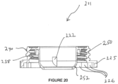
- FIG. 20 A side sectional view of inner member (211) is shown in Figure 20 in which teeth (226) are shown.
- Figure 20 also details thread (238) located on the internal surface of rim (225) that engages a corresponding thread (not shown) located on container (200) to thereby secure inner member (211) to container (200).
- Figure 20 also details thread (240) located on the external surface of rim (225) that serves to connect inner member (211) to outer member (212).
- Figure 20 also details flexible tongue (222) used to prevent outer member (212) from being removed from inner member (211).
- Figure 20 also details internal annulus (250) which includes base portion (252) that forms part of a first seal when the inner periphery (254) of base portion (252) abuts the outer periphery (233 - see Figure 24 ) of base portion (232 - see Figure 24 ) of outer member (212) when outer member (212) is in a first (closed) position.
- internal annulus (250) which includes base portion (252) that forms part of a first seal when the inner periphery (254) of base portion (252) abuts the outer periphery (233 - see Figure 24 ) of base portion (232 - see Figure 24 ) of outer member (212) when outer member (212) is in a first (closed) position.
- outer member (212) The features of outer member (212) will now be described with reference to Figures 21 to 24 .
- Figure 21 shows a side view of outer member (212) detailing lip (213) that serves to prevent, or at least minimise, dripping of liquid during dispensing.
- Figure 21 also details knurling (214) located on the external surface of rim (242).
- knurling (214) serves to provide manual grip of outer member (212) when it is moved (rotated) relative to inner member (211) in order to open the cap and allow dispensing of fluid.
- Knurling (214) also serves to provide mechanical grip when outer member (212) is engaged with inner member (211) and the assembled cap is driven onto container (200) by the use of a conventional capping chuck.
- FIG. 21 A top view of outer cap (212) is shown in Figure 21 that details knurling (214) located on rim (242). Ribs (220) are also detailed which define flow channels (221) through which liquid exits and/or air enters container (200) during dispensing. The function of ribs (220) and flow channels (221) is further described with reference to Figures 25 to 28 and also Figures 29 to 30 .
- Figure 22 also details top portion (231) and base portion (232) of central support structure (230 - shown in Figure 24 ).
- Central support structure (230) serves to support ribs (220) and also functions as part of a first seal that substantially prevents the flow of liquid when outer member (212) is in a first (closed) position.
- Central support structure also includes wall (237 - shown in Figure 24 ) that forms part of a second seal and that will be described in further detail with reference to Figure 28 .
- FIG 22 also details vent holes (224) which is an optional feature that is adopted when liquids that require continuous venting are stored in container (200).
- vent hole (224) is further described with reference to Figure 26 that shows a top view of cap (210) when in an assembled state in which inner member (211) is connected, by threaded connection, to outer member (212).
- Figure 22 further details bridges (218) that connect tamper ring (216) to rim (242) of outer member (212).
- Figure 23 shows outer member (212) in bottom view detailing teeth (228) that define a ratchet located on the internal surface of tamper ring (216). Also detailed are ribs (220) that that define flow channels (221). Vent hole (224) is also shown that is located on top portion (231) of central support structure (230 - shown in Figure 24 ). Also shown is top portion (232) located on central support structure (230 - shown in Figure 24 ).
- Figure 23 also details drive lugs (234) the function of which are described in detail with reference to Figures 25 to 28 that show cap (210) in an assembled state in which inner member (211) is connected, by threaded connection, to outer member (212).
- FIG 24 A side sectional view of outer member (212) is shown in Figure 24 in which lip (213) and ribs (220) are shown. Ribs (220) are connected to central support structure (230) which includes a top portion (231) and also a base portion (232). Base portion (232) serves to form part of a first seal and thereby substantially prevents the flow of liquid when outer member (212) is in a first (closed) position.
- the function of the first seal is further described with reference to Figures 25 to 28 which detail cap (210) when in an assembled state in which inner member (211) is connected, by threaded connection, to outer member (212).
- thread (244) located on an internal surface of rim (242) of outer member (212) that serves to connect, via threaded connection, inner (211) and outer (212) members.
- inner member (211) and outer member (212) when the cap is in an engaged state is shown in Figures 25 to 28 and, in particular, the sectional view shown in Figure 28 .
- cap (210) is shown in side view detailing outer member (212) that includes lip (113) that prevents, or at least minimises, any excess dripping of the liquid contents during dispensing.
- Outer member (212) also details knurling (214) surrounding the external surface of rim (215) of outer member (212).
- Figure 25 also shows tamper ring (216) connected to outer member (212) by a series of bridges (118 - visible in Figure 26 ) that may be broken by the manual application of a force when the cap is used and opened for the first time.
- bridges (218) Upon breakage of bridges (218), outer member (212) is able to be moved (rotated) relative to inner member (211) from a first (closed) position to a second (open) position to thereby open cap (210) and enable fluid contained within container (200) (shown in Figure 16 ) fitted with cap (210) to be dispensed from container (200).
- Cap (210) is shown in top view in Figure 26 , detailing, once again, lip (213) and knurling (214) located on outer member (212).
- Outer member (212) also includes ribs (220) disposed in a spoke arrangement and which define a plurality of flow channels (221) through which liquid passes during dispensing of the liquid from container (200) shown in Figure 16 .
- Outer member (212) further includes, in this embodiment, optional vent holes (224) that are useful when liquids that require continuous venting are stored within container (200).
- FIG. 27 a bottom view of cap (210) is shown that details vent hole (224) located on outer member (212).
- Figure 14 also details tamper ring (216) connected to outer member (212) of which only the top portion (231) of the central support structure (230 - see Figure 24 ) of outer member (212) is visible.
- Figure 27 also details dual ratchet systems adopted with cap (210) that each serve to secure inner member (211) to container (200) and also avoids a user tampering with the contents of container (200) prior to purchase and/or use.
- a ratchet broadly defines any mechanical device that allows continuous rotary motion of a part only in one direction whilst preventing motion of the part in the opposite direction.
- the first ratchet system includes a plurality of teeth (226) located on an internal surface of the periphery of rim (225) of inner member (211), wherein the plurality of teeth (226) engage one or more pawls located on the neck of container (200) (not shown).
- the one or more pawls located on the neck of container (200) prevent rotation of inner member (211) in a direction that would disengage inner member (211) from container (200). That is, teeth (226) located on inner member (211) and pawls (not shown) located on the neck of container (200) permit rotation of inner member only in one direction to thereby engage and secure inner member (211) to container (200) during installation of cap (210). Accordingly, once inner member (211) and/or cap (210) is installed on container (200), removal of inner member (211) and/or cap (210) is not possible unless excessive force is applied which would likely damage inner member (211) and/or container (200).
- the second ratchet system includes a plurality of teeth (227) located on an external surface of the periphery of rim (225) of inner member (211) wherein plurality of teeth (227) engage one or more teeth (228) located on an internal surface of tamper ring (216). Accordingly, whilst bridges (218- shown in Figure 26 ) remain intact, rotation of outer member (212) relative to inner member (211) is restricted thereby preventing movement of outer member (212) from an first (closed) position to a second (open position).
- outer member (212) Upon breakage of bridges (218) by the manual application of a force when the cap is used and opened for the first, outer member (212) is then able to be moved (rotated) relative to inner member (211) from a first (closed) position to a second (open) position to thereby open cap (210) and enable liquid contained within container (200) to be dispensed from container (200) through a dispensing opening of cap (210).
- Figure 27 also shows internal annulus (250) within internal member (211) having base portion (252) that extends radially inwardly a sufficient distance such that inner periphery (254) of base portion (252) forms part of a first seal and abuts outer periphery (233) of base portion (232 of support structure 230 - shown in Figure 28 ) when outer member (212) is in a first (closed) position.
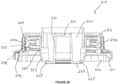
- Figure 28 is a sectional view of cap (210) showing inner member (211) and outer member (212) in an engaged state.
- Figure 28 details teeth (226) located on an internal surface of the periphery of rim (225) that form part of a first ratchet system as previously described.
- Figure 28 also details thread (238) located on an internal surface of rim (225) of inner member (211) that serves to engage, by threaded connection, inner member (211) to the neck of container (200) (not shown).
- Figure 28 further details thread (240) located on an external surface of rim (225) of inner member (211) that serves to engage inner member (211) to outer member (212) by threaded connection to thread (244) located on an internal surface of rim (242) of outer member (212).
- Figure 28 also details ribs (220) that, as previously discussed, serve to avoid or at least ameliorate the "glugging" of liquid as it exits container (200) during dispensing, and which also serve to permit air flow back into container (200) during dispensing thereby permitting and/or promoting liquid flow without having to puncture container (200).
- cap (210) is installed on container (200) whilst assembled, that is, when the inner (211) and outer (212) members are in an engaged state, using an automatic capping machine.
- Such machines allow for continuous capping of containers using one or multiple chuck heads and are ideal for use in facilities with high volume production.
- cap (210) In order to install cap (210) on container (200), the chuck of a conventional capping machine (not shown) grips outer member (212) of cap (210) and positions same over the neck (not shown) of container (210). Whilst not shown in any one of Figures 16 to 28 , it will be appreciated the opening of container (200) includes a neck portion on which a thread is located on the external surface that is able to engage thread (238) located on the internal surface of rim (225) of inner member (211). In order to engage and secure cap (210) on container (200), capping chuck rotates cap (210) in a direction that serves to engage thread (238) of inner member (211) with the thread located on the neck of container (200).
- drive lugs (234) located on outer member (212) engage and interlock guide lugs (236) (shown in Figure 18 ) located on inner member (211) which drive inner member (211) and engage same with the thread located on the neck of container (200) without applying excess pressure on the threads connecting inner and outer members.
- drive lugs (234) located on outer member (212) engage and interlock guide lugs (236) (shown in Figure 18 ) located on inner member (211) which drive inner member (211) and engage same with the thread located on the neck of container (200) without applying excess pressure on the threads connecting inner and outer members.
- drive lugs (234) and guide lugs (236) also assists in minimising the force required to be applied by a user in order to loosen outer member (112) from inner member (111) to thereby open container (200) in order to dispense liquid contained therein.
- Figure 28 also shows first seal (235 - see also Figure 27 ) formed between outer periphery (233) of base portion (232) of outer member (212) and inner periphery (254) of base portion (252) of inner member (211). It will be understood that first seal (235) serves to substantially prevent the flow and exit of liquid out of container (200) through dispensing opening of cap (210) when outer member (212) is in a first (closed) position.
- Figure 28 further shows second seal (239) formed between wall (237) that abuts the wall of internal annulus (250) wherein second seal (239) substantially diverts liquid to flow through channels (121) and away from the cavity defined between inner (211) and outer (212) members that house the thread mechanism.
- cap (300) according to an embodiment of the invention is shown when fitted to a bottle (310) wherein cap (300) is shown in a closed position ( Figure 29 ) and also in an open position ( Figure 30 ).
- Figure 29 details first (333), second (339) and third seals.
- First seal (333) is formed between base portion (332) of central support structure (330) located on outer member (312) that abuts inner periphery (354) of base portion (352) located on inner member (311) when outer member (312) is in a first (closed) position as shown in Figure 29 . Accordingly, liquid flow out of container (310) is substantially prevented when cap (300) is in a closed state and first seal is active.
- Second seal (339) is formed between wall (337) that abuts the wall of internal annulus (350) to form second seal (339) that substantially diverts liquid to flow through channels (321 - see Figure 30 ) and away from the cavity defined between inner (311) and outer (312) members that house the thread mechanism when cap (300) is in an open state.
- cap (300) The threaded connection between inner member (311) and outer member (312) enables cap (300) to be moved from a first (closed) position (as shown in Figure 29 ) to a second (open) position (as shown in Figure 30 ) to thereby define flow channel (321) through which liquid can flow and exit container (310) when in a sufficiently tilted state.
- inner member (311) and outer member (312) enable outer member (312) to be loosened from inner member (311) wherein the rate of liquid flow exiting container (310) is based upon the extent to which outer member (312) is loosened from inner member (311).
- Figure 29 also details third seal (341) that substantially prevents liquid flow within the cavity defined between container (300) and the inner wall of inner member (311) when the cap (300) is in sealing engagement with container (310).
- spoked ribbed arrangement that defines the plurality of flow channels (321) encourages air to flow in at least one or more channels (321) and thereby enter container (300) during dispensing of liquid which mitigates the "glugging" effect.
- the central support structure of the outer member that defines the ribs (320) and fluid flow channels (321), and also the internal annulus of the inner member are configured such that these portions substantially extend (or are recessed) within the container when the cap is fitted over the container opening.
- This arrangement assists in avoiding, or at least minimises, any parts jutting out from the container which strengthens the arrangement and minimises the risk of breakage or damage of any parts.
- This arrangement also permits and/or facilitates storage and/or stacking of the containers during transport and storage.
- Figures 32 and 33 show the container/cap assemblies of Figures 1 and 16 , respectively, shown in side sectional view in which the cap is in sealing engagement with the container.
- the flow passage defined by ribs (120, 220) extends substantially into the container when the cap housing is in sealing engagement with the container, the plurality of channels (121, 221) within the cap flow passage do not project substantially beyond the outer perimeter of the container, thereby allowing/enabling stacking of the containers during, for example, storage and/or transport.
- cap in accordance with the invention may be manufactured from a variety of materials and by any conventional method.
- any suitable polymer material may be adopted including, but not limited to, polypropylene (PP), low density polyethylene (LDPE) or high density polyethylene (HDPE).
- the caps may also be made using any suitable manufacturing process including, but not limited to, 3D (additive) printing technology or injection moulding.
- the caps are injection moulded using polypropylene (PP).
- the cap and container/cap assembly of the present invention assists in promoting controlled flow and avoids, or at least ameliorates, splashing/spillage of fluids during dispensing.
- the cap and container/cap assembly of the present invention also avoids the need to puncture the container in order to promote flow of the dispensing fluid.
- the cap is substantially circular in shape such that any conventional capping chuck to able to be adopted during manufacture and assembly of the sealed (capped) container.
- the circular shape avoids any components or sections jutting out from the cap which could be damaged and/or broken during transport or storage of the cap and container assembly.
- the cap may be supplied with the inner and outer members in an engaged state wherein the assembled cap is also located on a container.
- the cap may be supplied separately in which the inner and outer members are in engaged state such that the assembled cap only needs to be applied to any container of choice.
- the cap may be manufactured in a variety of sizes and configured to fit, by threaded engagement, containers/bottles of a variety of shapes and sizes.
- the cap and container/cap assembly of the present invention further avoids the need to adopt additional parts for connection to the container in order to promote and/or achieve a more controlled flow of fluid from the container during dispensing. Avoiding the need for additional parts reduces the risk of loss of any such parts thereby ensuring that a container is able to adequately re-sealed in the event only a portion of its contents are dispensed at any given time. All these factors contribute that a cap and container/cap assembly that is more convenient to use and reduces the risk of any occupational health and safety hazards.
Landscapes
- Engineering & Computer Science (AREA)
- Mechanical Engineering (AREA)
- Closures For Containers (AREA)
Claims (14)
- Bouchon (110) pour récipient (100) comprenant une ouverture de distribution utilisable pour être sélectivement fermée hermétiquement et un logement configuré pour une mise en prise de scellement avec une ouverture de récipient, ledit logement comprenant un élément extérieur (112) et un élément intérieur (111), ledit élément extérieur (112) définissant un passage le long d'un axe longitudinal de celui-ci, le passage présentant une pluralité de nervures (120) disposées dans le passage et s'étendant radialement depuis un emplacement à proximité d'une périphérie extérieure de l'élément extérieur (112) vers une structure de support centrale (130), dans lequel la structure de support centrale (130) comprend une partie supérieure (131) et une partie de base (132), et la structure de support centrale (130) s'étendant sensiblement le long dudit axe longitudinal pour définir ainsi un agencement à rayons et une pluralité de canaux d'écoulement fermés (121), dans lequel chaque canal d'écoulement fermé (121) est défini par la surface de deux nervures parmi la pluralité de nervures, la structure de support centrale (130) et une surface interne de l'élément extérieur (112) qui, lorsque le récipient se trouve dans un état suffisamment incliné, amène un liquide dans le récipient à être sensiblement en contact avec la surface des nervures (120) pendant qu'il s'écoule à travers un ou plusieurs canaux parmi la pluralité de canaux d'écoulement fermés (121) et pendant qu'il sort de l'ouverture de distribution, dans lequel au moins un canal d'écoulement (121) est un canal d'écoulement de liquide à travers lequel un liquide s'écoule hors de l'ouverture de distribution lorsqu'elle n'est plus fermée hermétiquement, caractérisé en ce que les nervures (120) sont reliées à la structure de support centrale (130) de ladite partie supérieure (131) à ladite partie de base (132).
- Bouchon (110) selon la revendication 1, dans lequel l'élément intérieur (111) est configuré pour se mettre en prise avec l'ouverture de récipient, et dans lequel l'élément extérieur (112) est configuré pour se mettre en prise avec l'élément intérieur (111).
- Bouchon (110) selon la revendication 2, dans lequel l'élément intérieur (111) et l'élément extérieur (112) sont mis en prise par une liaison filetée.
- Bouchon (110) selon la revendication 2 ou 3, dans lequel l'élément extérieur (112) est mobile entre une première position, dans laquelle l'élément extérieur (112) est serré sur l'élément intérieur (111) et un premier joint est fonctionnel entre l'élément extérieur (112) et l'élément intérieur (111) pour empêcher sensiblement l'écoulement de liquide hors de l'ouverture de distribution, et une seconde position, dans laquelle l'élément extérieur (112) est desserré de l'élément intérieur (111) et dans lequel le premier joint est inopérant, de sorte qu'il n'empêche pas le liquide de s'écouler hors de l'ouverture de distribution.
- Bouchon (110) selon la revendication 4, dans lequel un débit de liquide à travers l'ouverture de distribution est basé sur un degré selon lequel l'élément extérieur (112) est desserré de l'élément intérieur (111).
- Bouchon (110) selon l'une quelconque des revendications 2 à 5, comprenant en outre une ou plusieurs languettes flexibles (122) situées sur l'élément extérieur (112) et qui limitent la rotation de l'élément extérieur (112) par rapport à l'élément intérieur (111), en empêchant ainsi le retrait de l'élément extérieur (112) de l'élément intérieur (111).
- Bouchon (110) selon l'une quelconque des revendications précédentes, dans lequel ladite partie de base (132) s'étend radialement vers l'extérieur d'une distance suffisante pour qu'une périphérie extérieure (133) de la partie de base de structure de support (132) soit disposée dans un trajet d'écoulement de liquide et/ou d'air à travers la pluralité de canaux (121) et fasse partie d'un premier joint.
- Bouchon (110) selon la revendication 7, dans lequel l'élément intérieur (111) comprend un espace annulaire interne (150) qui définit au moins partiellement ledit passage, l'espace annulaire interne (150) comprenant une partie de base (152) qui s'étend radialement vers l'intérieur d'une distance suffisante pour qu'une périphérie intérieure (154) de la partie de base d'espace annulaire interne (152) fasse partie dudit premier joint (135) et soit amenée à venir en butée contre la périphérie extérieure (133) de la partie de base de structure de support (132) lorsque l'élément extérieur (112) se trouve dans ladite première position.
- Procédé de distribution de liquide depuis un récipient (100), le procédé comprenant l'inclinaison du récipient (100) pour amener un liquide dans le récipient (100) à sortir à travers une ouverture de distribution d'un bouchon (110) selon l'une quelconque des revendications 1 à 8.
- Procédé selon la revendication 9, dans lequel l'élément intérieur (111) est configuré pour se mettre en prise avec l'ouverture de récipient, et l'élément extérieur (112) est configuré pour se mettre en prise avec l'élément intérieur (111), dans lequel l'élément extérieur (112) est déplacé entre une première position, dans laquelle l'élément extérieur (112) est serré sur l'élément intérieur (111), et un premier joint est fonctionnel entre l'élément extérieur (112) et l'élément intérieur (111) pour empêcher sensiblement l'écoulement de liquide hors de l'ouverture de distribution, et une seconde position, dans laquelle l'élément extérieur (112) est desserré de l'élément intérieur (111) et dans lequel le premier joint est inopérant, de sorte qu'il n'empêche pas le liquide de s'écouler hors de l'ouverture de distribution, pour distribuer ainsi un liquide depuis le récipient.
- Procédé selon la revendication 9 ou 10, dans lequel un débit de liquide à travers l'ouverture de distribution est commandé sur la base du degré selon lequel l'élément extérieur (112) est desserré de l'élément intérieur (111).
- Ensemble récipient comprenant un récipient (100) et un bouchon (110) selon l'une quelconque des revendications 1 à 8.
- Ensemble récipient (110) selon la revendication 12, dans lequel, lorsque le bouchon (110) est mis en prise de fermeture étanche avec le récipient (100), le passage s'étend sensiblement dans le récipient (100).
- Procédé de fabrication d'un bouchon (110) permettant une mise en prise de fermeture étanche avec une ouverture de récipient, le procédé comprenant la fabrication additive d'un logement définissant un passage le long d'un axe longitudinal de celui-ci, le logement comprenant un élément extérieur (112) et un élément intérieur (111), ledit élément extérieur (112) définissant un passage le long d'un axe longitudinal de celui-ci, le passage comportant une pluralité de nervures (120) disposées dans le passage et s'étendant radialement depuis un emplacement à proximité d'une périphérie extérieure (133) de l'élément extérieur (112) vers une structure de support centrale (130) comprenant une partie supérieure (131) et une partie de base (132), les nervures (120) étant reliées à la structure de support centrale (130) depuis ladite partie supérieure (131) vers ladite partie de base (132), la structure de support centrale (130) s'étendant sensiblement le long dudit axe longitudinal pour définir ainsi un agencement à rayons et une pluralité de canaux d'écoulement fermés (121), chaque canal d'écoulement fermé (120) étant défini par la surface de deux nervures parmi la pluralité de nervures (120), la structure de support centrale (130) et une surface interne de l'élément extérieur (112), de sorte que, lorsque le récipient se trouve dans un état suffisamment incliné, un liquide dans le récipient est sensiblement en contact avec la surface des nervures (120) pendant qu'il s'écoule à travers un ou plusieurs de la pluralité de canaux d'écoulement fermés (121) et pendant qu'il sort par une ouverture de distribution du bouchon (110).
Applications Claiming Priority (1)
| Application Number | Priority Date | Filing Date | Title |
|---|---|---|---|
| PCT/AU2018/051329 WO2020118344A1 (fr) | 2018-12-12 | 2018-12-12 | Bouchon pour distribution de liquides à partir d'un récipient |
Publications (4)
| Publication Number | Publication Date |
|---|---|
| EP3894332A1 EP3894332A1 (fr) | 2021-10-20 |
| EP3894332A4 EP3894332A4 (fr) | 2022-07-27 |
| EP3894332C0 EP3894332C0 (fr) | 2025-02-05 |
| EP3894332B1 true EP3894332B1 (fr) | 2025-02-05 |
Family
ID=71075334
Family Applications (1)
| Application Number | Title | Priority Date | Filing Date |
|---|---|---|---|
| EP18942732.1A Active EP3894332B1 (fr) | 2018-12-12 | 2018-12-12 | Bouchon pour distribution de liquides à partir d'un récipient |
Country Status (3)
| Country | Link |
|---|---|
| US (1) | US11993425B2 (fr) |
| EP (1) | EP3894332B1 (fr) |
| WO (1) | WO2020118344A1 (fr) |
Families Citing this family (1)
| Publication number | Priority date | Publication date | Assignee | Title |
|---|---|---|---|---|
| USD1078930S1 (en) * | 2023-02-16 | 2025-06-10 | The Foundation Group, Inc. | Cap for spray tank |
Family Cites Families (19)
| Publication number | Priority date | Publication date | Assignee | Title |
|---|---|---|---|---|
| AT12359B (fr) * | 1902-07-24 | 1903-06-25 | Johan Frederik Adolph Rruun | |
| US4261487A (en) | 1979-09-21 | 1981-04-14 | King Seeley Thermos Co. | Pour through stopper |
| CH691587A5 (it) | 1995-12-14 | 2001-08-31 | Luthe Ag | Chiusura di sicurezza per bottiglie di liquori e simili. |
| US6213351B1 (en) | 1999-12-27 | 2001-04-10 | Courtesy Corporation | Push body valve closure |
| BR0101765A (pt) | 2000-11-27 | 2002-07-09 | Alpha Werke Alwin Lehner Gmbh | Fecho de material sintético flexìvel, para recipientes, especialmente para garrafas |
| EP1236652A1 (fr) | 2001-03-02 | 2002-09-04 | Crown Cork & Seal Technologies Corporation | Fermeture avec dispositif pour régulation d'écoulement |
| US6938794B2 (en) * | 2001-04-26 | 2005-09-06 | Innatech, Llc | Lip actuated valve closure for a drinking bottle |
| US6997359B2 (en) | 2001-09-12 | 2006-02-14 | Pepsico, Inc. | Bottle closure |
| US6427881B1 (en) * | 2001-10-09 | 2002-08-06 | Rexam Medical Packaging Inc. | Edge seal closure |
| KR100860834B1 (ko) * | 2001-11-07 | 2008-09-29 | 노희권 | 음료용기 개폐장치 |
| WO2003039986A1 (fr) * | 2001-11-07 | 2003-05-15 | Hee Kwon Rho | Bouchon pour recipient de boissons |
| PL1943158T3 (pl) * | 2005-10-06 | 2011-05-31 | Capartis Ag | Zamknięcie pojemnika |
| CA2893662C (fr) | 2012-12-19 | 2020-06-09 | Comar, Llc | Fermeture a l'epreuve des enfants a sollicitation ascendante pour medicaments liquides |
| US9758281B2 (en) | 2014-03-06 | 2017-09-12 | Fisher Scientific Company, L.L.C. | Tamper-evident closure assembly having two tamper-evidencing members, and related methods |
| US9908669B2 (en) | 2014-10-09 | 2018-03-06 | Container Packaging Systems, Inc. | Anti-glug device for liquid containers and pour spouts |
| US9981786B2 (en) | 2016-02-16 | 2018-05-29 | Vection Ltd. | Method and apparatus for controlled transfer of fluid |
| US11097876B2 (en) * | 2017-01-07 | 2021-08-24 | Rungkarn Chalermwinsuekun | Non-spill drinking container lid device |
| IT201700048753A1 (it) | 2017-05-05 | 2018-11-05 | Silvia Ferrari | Tappo per un recipiente con erogatore richiudibile con evidenza di prima apertura |
| ES1215591Y (es) | 2018-06-15 | 2018-10-11 | Bericap Sa | Tapon roscado |
-
2018
- 2018-12-12 US US17/413,720 patent/US11993425B2/en active Active
- 2018-12-12 WO PCT/AU2018/051329 patent/WO2020118344A1/fr not_active Ceased
- 2018-12-12 EP EP18942732.1A patent/EP3894332B1/fr active Active
Also Published As
| Publication number | Publication date |
|---|---|
| EP3894332A1 (fr) | 2021-10-20 |
| EP3894332C0 (fr) | 2025-02-05 |
| US20220017271A1 (en) | 2022-01-20 |
| US11993425B2 (en) | 2024-05-28 |
| EP3894332A4 (fr) | 2022-07-27 |
| WO2020118344A1 (fr) | 2020-06-18 |
Similar Documents
| Publication | Publication Date | Title |
|---|---|---|
| US12291379B2 (en) | Container, closure, and methods for manufacture | |
| EP3265396B1 (fr) | Douille et couvercle de surbouchage pour celle-ci | |
| US5533633A (en) | Container closure assembly | |
| EP1327588B1 (fr) | Fermeture à décompression | |
| EP4192753B1 (fr) | Fermeture de distribution de gouttes en deux parties | |
| CN103648923A (zh) | 具有用于将添加剂引入到容器的内含物中的机构的容器封闭装置 | |
| US11465898B2 (en) | Catch releasing capless fuel-filler bottle | |
| JP2007514612A (ja) | 容器用ねじキャップ | |
| EP3894332B1 (fr) | Bouchon pour distribution de liquides à partir d'un récipient | |
| US20230249882A1 (en) | Bottle cap with a flip lid | |
| AU2018232893B2 (en) | Cap for dispensing liquids from a container | |
| WO1999026855A1 (fr) | Fermetures pour produits pressurises | |
| EP3409612B1 (fr) | Ensacheur pour emballage alimentaire | |
| US20250074663A1 (en) | Closure and package with closure | |
| JP2024122027A (ja) | 樹脂製キャップおよびキャップユニット | |
| JP2024173515A (ja) | 合成樹脂製螺子キャップ |
Legal Events
| Date | Code | Title | Description |
|---|---|---|---|
| STAA | Information on the status of an ep patent application or granted ep patent |
Free format text: STATUS: THE INTERNATIONAL PUBLICATION HAS BEEN MADE |
|
| PUAI | Public reference made under article 153(3) epc to a published international application that has entered the european phase |
Free format text: ORIGINAL CODE: 0009012 |
|
| STAA | Information on the status of an ep patent application or granted ep patent |
Free format text: STATUS: REQUEST FOR EXAMINATION WAS MADE |
|
| 17P | Request for examination filed |
Effective date: 20210712 |
|
| AK | Designated contracting states |
Kind code of ref document: A1 Designated state(s): AL AT BE BG CH CY CZ DE DK EE ES FI FR GB GR HR HU IE IS IT LI LT LU LV MC MK MT NL NO PL PT RO RS SE SI SK SM TR |
|
| DAV | Request for validation of the european patent (deleted) | ||
| DAX | Request for extension of the european patent (deleted) | ||
| A4 | Supplementary search report drawn up and despatched |
Effective date: 20220629 |
|
| RIC1 | Information provided on ipc code assigned before grant |
Ipc: B65D 50/00 20060101ALI20220623BHEP Ipc: B65D 39/00 20060101ALI20220623BHEP Ipc: B65D 47/32 20060101ALI20220623BHEP Ipc: B65D 51/18 20060101ALI20220623BHEP Ipc: B65D 51/16 20060101ALI20220623BHEP Ipc: B65D 47/24 20060101ALI20220623BHEP Ipc: B65D 47/06 20060101ALI20220623BHEP Ipc: B65D 47/04 20060101AFI20220623BHEP |
|
| STAA | Information on the status of an ep patent application or granted ep patent |
Free format text: STATUS: EXAMINATION IS IN PROGRESS |
|
| 17Q | First examination report despatched |
Effective date: 20230920 |
|
| GRAP | Despatch of communication of intention to grant a patent |
Free format text: ORIGINAL CODE: EPIDOSNIGR1 |
|
| STAA | Information on the status of an ep patent application or granted ep patent |
Free format text: STATUS: GRANT OF PATENT IS INTENDED |
|
| INTG | Intention to grant announced |
Effective date: 20240726 |
|
| GRAS | Grant fee paid |
Free format text: ORIGINAL CODE: EPIDOSNIGR3 |
|
| GRAA | (expected) grant |
Free format text: ORIGINAL CODE: 0009210 |
|
| STAA | Information on the status of an ep patent application or granted ep patent |
Free format text: STATUS: THE PATENT HAS BEEN GRANTED |
|
| AK | Designated contracting states |
Kind code of ref document: B1 Designated state(s): AL AT BE BG CH CY CZ DE DK EE ES FI FR GB GR HR HU IE IS IT LI LT LU LV MC MK MT NL NO PL PT RO RS SE SI SK SM TR |
|
| REG | Reference to a national code |
Ref country code: GB Ref legal event code: FG4D |
|
| REG | Reference to a national code |
Ref country code: CH Ref legal event code: EP |
|
| REG | Reference to a national code |
Ref country code: DE Ref legal event code: R096 Ref document number: 602018079004 Country of ref document: DE |
|
| REG | Reference to a national code |
Ref country code: IE Ref legal event code: FG4D |
|
| U01 | Request for unitary effect filed |
Effective date: 20250305 |
|
| U07 | Unitary effect registered |
Designated state(s): AT BE BG DE DK EE FI FR IT LT LU LV MT NL PT RO SE SI Effective date: 20250312 |
|
| PG25 | Lapsed in a contracting state [announced via postgrant information from national office to epo] |
Ref country code: RS Free format text: LAPSE BECAUSE OF FAILURE TO SUBMIT A TRANSLATION OF THE DESCRIPTION OR TO PAY THE FEE WITHIN THE PRESCRIBED TIME-LIMIT Effective date: 20250505 |
|
| PG25 | Lapsed in a contracting state [announced via postgrant information from national office to epo] |
Ref country code: PL Free format text: LAPSE BECAUSE OF FAILURE TO SUBMIT A TRANSLATION OF THE DESCRIPTION OR TO PAY THE FEE WITHIN THE PRESCRIBED TIME-LIMIT Effective date: 20250205 |
|
| PG25 | Lapsed in a contracting state [announced via postgrant information from national office to epo] |
Ref country code: ES Free format text: LAPSE BECAUSE OF FAILURE TO SUBMIT A TRANSLATION OF THE DESCRIPTION OR TO PAY THE FEE WITHIN THE PRESCRIBED TIME-LIMIT Effective date: 20250205 |
|
| PG25 | Lapsed in a contracting state [announced via postgrant information from national office to epo] |
Ref country code: IS Free format text: LAPSE BECAUSE OF FAILURE TO SUBMIT A TRANSLATION OF THE DESCRIPTION OR TO PAY THE FEE WITHIN THE PRESCRIBED TIME-LIMIT Effective date: 20250605 Ref country code: NO Free format text: LAPSE BECAUSE OF FAILURE TO SUBMIT A TRANSLATION OF THE DESCRIPTION OR TO PAY THE FEE WITHIN THE PRESCRIBED TIME-LIMIT Effective date: 20250505 |
|
| PG25 | Lapsed in a contracting state [announced via postgrant information from national office to epo] |
Ref country code: HR Free format text: LAPSE BECAUSE OF FAILURE TO SUBMIT A TRANSLATION OF THE DESCRIPTION OR TO PAY THE FEE WITHIN THE PRESCRIBED TIME-LIMIT Effective date: 20250205 |
|
| PG25 | Lapsed in a contracting state [announced via postgrant information from national office to epo] |
Ref country code: GR Free format text: LAPSE BECAUSE OF FAILURE TO SUBMIT A TRANSLATION OF THE DESCRIPTION OR TO PAY THE FEE WITHIN THE PRESCRIBED TIME-LIMIT Effective date: 20250506 |
|
| PG25 | Lapsed in a contracting state [announced via postgrant information from national office to epo] |
Ref country code: SM Free format text: LAPSE BECAUSE OF FAILURE TO SUBMIT A TRANSLATION OF THE DESCRIPTION OR TO PAY THE FEE WITHIN THE PRESCRIBED TIME-LIMIT Effective date: 20250205 |
|
| PG25 | Lapsed in a contracting state [announced via postgrant information from national office to epo] |
Ref country code: CZ Free format text: LAPSE BECAUSE OF FAILURE TO SUBMIT A TRANSLATION OF THE DESCRIPTION OR TO PAY THE FEE WITHIN THE PRESCRIBED TIME-LIMIT Effective date: 20250205 |
|
| PG25 | Lapsed in a contracting state [announced via postgrant information from national office to epo] |
Ref country code: SK Free format text: LAPSE BECAUSE OF FAILURE TO SUBMIT A TRANSLATION OF THE DESCRIPTION OR TO PAY THE FEE WITHIN THE PRESCRIBED TIME-LIMIT Effective date: 20250205 |
|
| PLBE | No opposition filed within time limit |
Free format text: ORIGINAL CODE: 0009261 |
|
| STAA | Information on the status of an ep patent application or granted ep patent |
Free format text: STATUS: NO OPPOSITION FILED WITHIN TIME LIMIT |
|
| PGFP | Annual fee paid to national office [announced via postgrant information from national office to epo] |
Ref country code: GB Payment date: 20251219 Year of fee payment: 8 |
|
| 26N | No opposition filed |
Effective date: 20251106 |
|
| U20 | Renewal fee for the european patent with unitary effect paid |
Year of fee payment: 8 Effective date: 20251230 |