EP3894652B1 - Eckverbindungsclip mit selbststützender platte - Google Patents
Eckverbindungsclip mit selbststützender platte Download PDFInfo
- Publication number
- EP3894652B1 EP3894652B1 EP19895864.7A EP19895864A EP3894652B1 EP 3894652 B1 EP3894652 B1 EP 3894652B1 EP 19895864 A EP19895864 A EP 19895864A EP 3894652 B1 EP3894652 B1 EP 3894652B1
- Authority
- EP
- European Patent Office
- Prior art keywords
- clip
- backing plate
- frame member
- aperture
- extending
- Prior art date
- Legal status (The legal status is an assumption and is not a legal conclusion. Google has not performed a legal analysis and makes no representation as to the accuracy of the status listed.)
- Active
Links
Images


Classifications
-
- E—FIXED CONSTRUCTIONS
- E06—DOORS, WINDOWS, SHUTTERS, OR ROLLER BLINDS IN GENERAL; LADDERS
- E06B—FIXED OR MOVABLE CLOSURES FOR OPENINGS IN BUILDINGS, VEHICLES, FENCES OR LIKE ENCLOSURES IN GENERAL, e.g. DOORS, WINDOWS, BLINDS, GATES
- E06B3/00—Window sashes, door leaves, or like elements for closing wall or like openings; Layout of fixed or moving closures, e.g. windows in wall or like openings; Features of rigidly-mounted outer frames relating to the mounting of wing frames
- E06B3/96—Corner joints or edge joints for windows, doors, or the like frames or wings
- E06B3/964—Corner joints or edge joints for windows, doors, or the like frames or wings using separate connection pieces, e.g. T-connection pieces
- E06B3/968—Corner joints or edge joints for windows, doors, or the like frames or wings using separate connection pieces, e.g. T-connection pieces characterised by the way the connecting pieces are fixed in or on the frame members
- E06B3/9684—Corner joints or edge joints for windows, doors, or the like frames or wings using separate connection pieces, e.g. T-connection pieces characterised by the way the connecting pieces are fixed in or on the frame members by hooking protrusions on the connecting piece in openings of the frame member, e.g. by snap-locking
-
- E—FIXED CONSTRUCTIONS
- E06—DOORS, WINDOWS, SHUTTERS, OR ROLLER BLINDS IN GENERAL; LADDERS
- E06B—FIXED OR MOVABLE CLOSURES FOR OPENINGS IN BUILDINGS, VEHICLES, FENCES OR LIKE ENCLOSURES IN GENERAL, e.g. DOORS, WINDOWS, BLINDS, GATES
- E06B3/00—Window sashes, door leaves, or like elements for closing wall or like openings; Layout of fixed or moving closures, e.g. windows in wall or like openings; Features of rigidly-mounted outer frames relating to the mounting of wing frames
- E06B3/04—Wing frames not characterised by the manner of movement
- E06B3/06—Single frames
-
- E—FIXED CONSTRUCTIONS
- E06—DOORS, WINDOWS, SHUTTERS, OR ROLLER BLINDS IN GENERAL; LADDERS
- E06B—FIXED OR MOVABLE CLOSURES FOR OPENINGS IN BUILDINGS, VEHICLES, FENCES OR LIKE ENCLOSURES IN GENERAL, e.g. DOORS, WINDOWS, BLINDS, GATES
- E06B3/00—Window sashes, door leaves, or like elements for closing wall or like openings; Layout of fixed or moving closures, e.g. windows in wall or like openings; Features of rigidly-mounted outer frames relating to the mounting of wing frames
- E06B3/96—Corner joints or edge joints for windows, doors, or the like frames or wings
- E06B3/964—Corner joints or edge joints for windows, doors, or the like frames or wings using separate connection pieces, e.g. T-connection pieces
- E06B3/9642—Butt type joints with at least one frame member cut off square; T-shape joints
-
- E—FIXED CONSTRUCTIONS
- E06—DOORS, WINDOWS, SHUTTERS, OR ROLLER BLINDS IN GENERAL; LADDERS
- E06B—FIXED OR MOVABLE CLOSURES FOR OPENINGS IN BUILDINGS, VEHICLES, FENCES OR LIKE ENCLOSURES IN GENERAL, e.g. DOORS, WINDOWS, BLINDS, GATES
- E06B3/00—Window sashes, door leaves, or like elements for closing wall or like openings; Layout of fixed or moving closures, e.g. windows in wall or like openings; Features of rigidly-mounted outer frames relating to the mounting of wing frames
- E06B3/96—Corner joints or edge joints for windows, doors, or the like frames or wings
- E06B3/964—Corner joints or edge joints for windows, doors, or the like frames or wings using separate connection pieces, e.g. T-connection pieces
- E06B3/968—Corner joints or edge joints for windows, doors, or the like frames or wings using separate connection pieces, e.g. T-connection pieces characterised by the way the connecting pieces are fixed in or on the frame members
- E06B3/9687—Corner joints or edge joints for windows, doors, or the like frames or wings using separate connection pieces, e.g. T-connection pieces characterised by the way the connecting pieces are fixed in or on the frame members with screws blocking the connecting piece inside or on the frame member
-
- F—MECHANICAL ENGINEERING; LIGHTING; HEATING; WEAPONS; BLASTING
- F16—ENGINEERING ELEMENTS AND UNITS; GENERAL MEASURES FOR PRODUCING AND MAINTAINING EFFECTIVE FUNCTIONING OF MACHINES OR INSTALLATIONS; THERMAL INSULATION IN GENERAL
- F16B—DEVICES FOR FASTENING OR SECURING CONSTRUCTIONAL ELEMENTS OR MACHINE PARTS TOGETHER, e.g. NAILS, BOLTS, CIRCLIPS, CLAMPS, CLIPS OR WEDGES; JOINTS OR JOINTING
- F16B5/00—Joining sheets or plates, e.g. panels, to one another or to strips or bars parallel to them
- F16B5/0004—Joining sheets, plates or panels in abutting relationship
- F16B5/0032—Joining sheets, plates or panels in abutting relationship by moving the sheets, plates, or panels or the interlocking key parallel to the abutting edge
- F16B5/0036—Joining sheets, plates or panels in abutting relationship by moving the sheets, plates, or panels or the interlocking key parallel to the abutting edge and using hook and slot or keyhole-type connections
-
- F—MECHANICAL ENGINEERING; LIGHTING; HEATING; WEAPONS; BLASTING
- F16—ENGINEERING ELEMENTS AND UNITS; GENERAL MEASURES FOR PRODUCING AND MAINTAINING EFFECTIVE FUNCTIONING OF MACHINES OR INSTALLATIONS; THERMAL INSULATION IN GENERAL
- F16B—DEVICES FOR FASTENING OR SECURING CONSTRUCTIONAL ELEMENTS OR MACHINE PARTS TOGETHER, e.g. NAILS, BOLTS, CIRCLIPS, CLAMPS, CLIPS OR WEDGES; JOINTS OR JOINTING
- F16B7/00—Connections of rods or tubes, e.g. of non-circular section, mutually, including resilient connections
- F16B7/22—Connections of rods or tubes, e.g. of non-circular section, mutually, including resilient connections using hooks or like elements
-
- F—MECHANICAL ENGINEERING; LIGHTING; HEATING; WEAPONS; BLASTING
- F16—ENGINEERING ELEMENTS AND UNITS; GENERAL MEASURES FOR PRODUCING AND MAINTAINING EFFECTIVE FUNCTIONING OF MACHINES OR INSTALLATIONS; THERMAL INSULATION IN GENERAL
- F16B—DEVICES FOR FASTENING OR SECURING CONSTRUCTIONAL ELEMENTS OR MACHINE PARTS TOGETHER, e.g. NAILS, BOLTS, CIRCLIPS, CLAMPS, CLIPS OR WEDGES; JOINTS OR JOINTING
- F16B7/00—Connections of rods or tubes, e.g. of non-circular section, mutually, including resilient connections
- F16B7/18—Connections of rods or tubes, e.g. of non-circular section, mutually, including resilient connections using screw-thread elements
Definitions
- framed assemblies to provide doors, doorframes, window vents, and window frames.
- Commercial metal doors are one type of framed assembly and typically include vertical side frame members or “stiles" interconnected by top and bottom horizontal frame members or “rails.”
- the stiles and rails are typically hollow, rectangular tubes made from rolled sheet metal, extruded aluminum, or an extruded polymer.
- An intermediate rail is sometimes incorporated to provide additional structural rigidity, and infill panels (e.g., glass lites) can be placed in the rectangular openings defined by the interconnected stiles and rails.
- a conventional clip assembly 1000 typically includes an extruded clip 1002 (e.g., made of aluminum or another rigid material), two discrete backing plates 1004, and two threaded fasteners 1006.
- the clip 1002 can be mounted to a stile (not shown) by aligning holes 1008 formed in the clip 1002 with corresponding holes defined in the stile.
- the threaded fasteners 1006 are then extended through the aligned holes of the clip 1002 and the stile and received within threaded holes 1010 formed in the backing plates 1004, which are blindly supported within the interior of the stile.
- US2014186103 A1 discloses a connecting means for connecting posts and bars.
- EP 2322732 discloses a connecting means for connecting posts and bars.
- US 4607754 discloses a mounting bracket for joining posts and struts of a merchandising display.
- US 9127504 discloses a corner assembly for use with metal framed, floating panel glass doors, windows, or wall partitions.
- US 2016/123364 discloses a clip for assembling corners of hollow members.
- Embodiments disclosed herein include a framed assembly that includes a first frame member providing an inner vertical wall extending between opposing front and back surfaces and defining a slot, a second frame member positioned adjacent the first frame member at a corner joint and providing a horizontal wall extending between opposing front and back surfaces of the second frame member, and a clip having opposing front and back sides and providing a backing plate extending from the back side and a projection extending from the front side, wherein the backing plate is received within an interior of the first frame member via the slot, and the projection is received within an interior of the second frame member adjacent the horizontal wall.
- the framed assembly is selected from the group consisting of a door, a doorframe, a window vent, a window frame, a glazing panel, a curtain wall, a storefront, a skylight, and any combination thereof.
- the framed assembly includes a backing plate aperture defined in the backing plate, a clip aperture defined in the clip and coaxially aligned with the backing plate aperture, a stile aperture defined in the inner vertical wall and coaxially aligned with the backing plate aperture and the clip aperture when the backing plate is received in the slot, and a mechanical fastener extendable through coaxially aligned clip and backing plate apertures and the stile aperture to secure the clip to the first frame member.
- the framed assembly may additionally and/or alternatively include wherein the mechanical fastener comprises a threaded fastener or a rivet fastener.
- the framed assembly may additionally and/or alternatively include wherein the mechanical fastener forms an interference fit with at least one of the backing plate aperture and the stile aperture.
- the framed assembly includes a gap defined between the backing plate and the back side of the clip, and wherein a portion of the inner vertical wall is positioned within the gap when the clip is mounted to the first frame member.
- the framed assembly may additionally and/or alternatively include a fillet weld applied at an intersection between the inner vertical wall and the horizontal wall.
- the framed assembly may additionally and/or alternatively include a flange extending from an end of the clip, wherein heat from the fillet weld melts the flange and causes the flange to adhere to the second frame member.
- the framed assembly may additionally and/or alternatively include a plug weld that attaches the second frame member to the clip at the projection.
- Embodiments disclosed herein may further include a method of assembling a corner joint of a framed assembly that includes mounting a clip to an inner vertical wall of a first frame member by inserting a backing plate extending from a back side of the clip into a slot defined in the inner vertical wall, securing the clip to the first frame member at the inner vertical wall, receiving a projection extending from a front side of the clip within an interior of a second frame member, the second frame member providing a horizontal wall, forming a seam at an intersection between the first and second frame members as the second frame member is mounted to the clip, and joining the second frame member to the first frame member at one or more locations.
- the method may include securing the clip to the first frame member at the inner vertical wall includes coaxially aligning a stile aperture defined in the inner vertical wall with a backing plate aperture defined in the backing plate and a clip aperture defined in the clip, and extending a mechanical fastener through the clip aperture, the stile aperture and the backing plate aperture.
- the method may additionally and/or alternatively include wherein the mechanical fastener comprises a threaded fastener and the method further comprises threadably receiving the threaded aperture within the backing plate aperture.
- the method may additionally and/or alternatively include forming an interference fit with the mechanical fastener and at least one of the backing plate aperture and the stile aperture.
- a gap is defined between the backing plate and the back side of the clip, and mounting the clip to the inner vertical wall of a first frame member comprises positioning a portion of the inner vertical wall within the gap.
- the method may additionally and/or alternatively include wherein joining the second frame member to the first frame member comprises applying a fillet weld at an intersection between the inner vertical wall and the horizontal wall.
- the method may additionally and/or alternatively include melting a flange extending from an end of the clip with the fillet weld and thereby causing the flange to adhere to the second frame member.
- the method may additionally and/or alternatively include wherein joining the second frame member to the first frame member comprises applying a plug weld via a weld hole defined in the horizontal wall of the second frame member and thereby attaching the second frame member to the clip at the projection.
- the invention includes a clip assembly for a framed assembly that includes a body having a first end and a second end opposite the first end and defining one or more clip apertures, one or more backing plates projecting laterally from a back side of the body and extending downwardly therefrom such that a gap is defined between each backing plate and the backside of the body, wherein at least one backing plate aperture is defined in at least one of the backing plates, each of said backing plate aperture(s) being coaxially aligned with a corresponding one of the one or more clip apertures, one or more projections extending laterally from a front side of the body, and a mechanical fastener extendable through coaxially aligned clip and backing plate apertures.
- the clip assembly may further include a first flange extending vertically upward from the first end, and a second flange extending vertically downward from the second end.
- the clip assembly may additionally and/or alternatively include wherein the mechanical fastener comprises a threaded fastener or a rivet fastener.
- the present disclosure is generally related to framed assemblies for doors and windows and, more particularly, to improved clip assemblies that interconnect and stabilize adjacent frame members at a corner joint.
- the embodiments discussed herein describe new clip designs and assembly methods for framed assembly corner joints that eliminate the need for discrete backing plates to be blindly held in place within the interior of a vertical frame member (e.g., a stile) during assembly.
- the clips described herein may include backing plates integrally formed with the clips. Consequently, part count is reduced and the assembly methods described herein simplify and expedite the assembly process.
- One example framed assembly includes a first frame member providing an inner vertical wall extending between opposing front and back surfaces and defining a slot, and a second frame member positioned adjacent the first frame member at a corner joint and providing a horizontal wall extending between opposing front and back surfaces of the second frame member.
- a clip having opposing front and back sides may provide a backing plate extending from the back side and may further provide a projection extending from the front side. The backing plate may be received within an interior of the first frame member via the slot, and the projection may be received within an interior of the second frame member adjacent the horizontal wall.
- FIG. 1 is a front view of an example framed assembly 100 that may incorporate one or more principles of the present disclosure.
- the framed assembly 100 comprises a door that may be employed in any commercial or residential building setting.
- the principles of the present disclosure may be equally applicable to other types of framed assemblies including, but not limited to, doorframes, window vents, window frames, glazing panels (alternately referred to as "glazing units"), curtain walls, storefronts, skylights, or any combination thereof. Accordingly, while the following discussion is directed to a door framed assembly, other types of framed assemblies may equally incorporate the presently disclosed features.
- the framed assembly 100 includes a plurality of frame members, shown as a top frame member 102a, a bottom frame member 102b, and opposing side frame members 102c, 102d extending between the top and bottom frame members 102a,b.
- An optional intermediate frame member 102e may extend between the side frame members 102c,d at an intermediate location.
- top, bottom, and intermediate frame members 102a,b,e are alternately referred to as horizontally-extending "rails," and the side frame members 102c,d are alternately referred to as vertically-extending "stiles.” Accordingly, the top, bottom, and intermediate frame members 102a,b,e will be referred to herein as rails 102a,b,e, and the side frame members 102c,d will be referred to herein as first and second stiles 102c,d.
- the rails and stiles 102a-e may comprise hollow, generally rectangular tubes made of a variety of rigid materials including, but not limited to, aluminum, rolled sheet metal, a polymer, a composite material (e.g., fiberglass, carbon fiber, etc.), or any combination thereof.
- the first stile 102c includes conventional door hardware, such as a lock 104 and a door handle 106.
- the opposing second stile 102d includes pivot assemblies 108 provided at opposing ends of the stile 102d for pivotably mounting the framed assembly 100 within a doorframe (not shown).
- the rails and stiles 102a-e cooperatively surround and otherwise "frame" first and second center panels 110a and 110b, alternately referred to as "infill" panels. While two center panels 110a,b are depicted, more or less than two may be employed, without departing from the scope of the disclosure.
- the center panels 110a,b may each comprise glass lites and, in at least one embodiment, may comprise double paned glass including air, an inert gas, and/or a plastic film(s) between adjacent panes to control transmission of thermal energy.
- center panels 110a,b may alternatively comprise other types of infills such as, but not limited to, a glazing panel, polycarbonate, or another clear, translucent, tinted, or opaque panel, without departing from the scope of the disclosure.
- each rail 102a,b,e are joined to the adjacent stiles 102c,d at corresponding corner joints 112.
- the rails and stiles 102a-e may be arranged generally orthogonal to one another at the corner joints 112. In other embodiment, however, the angular offset between the interconnected adjacent rails and stiles 102a-e may be greater or less than 90°, without departing from the scope of the disclosure.
- one or more of the corner joints 112 may incorporate an improved clip assembly designed to align and join the rails 102a,b,e to the stiles 102c,d, and simultaneously stabilize the connection and thereby help mitigate the effects of heavy use and abuse on the framed assembly 100.
- the clip assemblies described herein also eliminate the need to blindly support and align discrete backing plates within the stiles 102c,d, thus providing cost and labor savings via simpler and faster assembly processes.
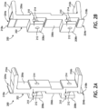
- FIGS. 2A and 2B depict front and back isometric views, respectively, of an example clip 200 that may be used in accordance with the present disclosure.
- the clip 200 may form part of an internal clip assembly operable to align and join a rail (e.g., rails 102a,b,e of FIG. 1 ) with an adjacent stile (e.g., stiles 102c,d of FIG. 1 ) at a corresponding corner joint 112 ( FIG. 1 ).
- the clip 200 may provide an elongated body 202 that includes a first or "upper" end 204a and a second or “lower” end 204b opposite the first end 204a.
- the body 202 may be made of a variety of rigid materials including, but not limited to, a metal (e.g., aluminum, an aluminum alloy, steel, a steel alloy, etc.), a polymer (e.g., nylon, polypropylene, polyetherimide, polycarbonate, polystyrene, etc.), a composite material (e.g., fiberglass, carbon fiber, etc.), or any combination thereof.
- the body 202 may be manufactured via a variety of known manufacturing processes including, but not limited to, extruding, injection molding, casting, stamping, machining, additive manufacturing (i.e., 3D printing), or any combination thereof.
- the body 202 is shown in FIGS. 2A-2B having specific dimensions, e.g., length, width, depth, etc.
- the principles of the present disclosure are equally applicable to clips having varying dimensions. Accordingly, the specific dimensions and shape of the body 202 depicted in FIG. 2 are shown for illustrative purposes and should not be considered limiting to the present disclosure.
- the clip 200 may be used to join members of various lengths, such as tall/short top and bottom rails, allowing a variety of structures to be assembled using a common clip, e.g., to produce a variety of framed assemblies exhibiting different dimensions.
- the clip 200 provides a first or "front" side 206a and a second or “back” side 206b opposite the front side 206a.
- one or both of the front and back sides 206a,b may be stepped or otherwise define a non-continuous surface extending between the first and second ends 204a,b.
- the stepped surfaces of the front and back sides 206a,b may help ease manufacturing of the clip 200, and may also provide added strength in areas where the clip 200 will be mounted to a stile (e.g., stiles 102c,d of FIG. 1 ).
- one or both of the front and back sides 206a,b may define generally planar or continuous surfaces extending between the first and second ends 204a,b, without departing from the scope of the disclosure.
- the clip defines one or more backing plates, shown as a first backing plate 208a and a second backing plate 208b vertically offset from the first backing plate 208a. While two backing plates 208a, b are depicted, more or less than two may be included on the clip 200, without departing from the scope of the disclosure. As illustrated, the backing plates 208a, b project laterally from the back side 206b of the body 202 and extend downwardly therefrom, thereby forming a gap 210 between each backing plate 208a, b and the back side 206b of the body 202. As described below, the gap 210 may provide an area to accommodate portions of an inner vertical wall of a stile (e.g., stiles 102c, d of FIG. 1 ), which helps mount the clip 200 to the stile.
- a stile e.g., stiles 102c, d of FIG. 1
- Each backing plate 208a, b defines a backing plate aperture 212 that coaxially aligns with a corresponding clip aperture 214 defined in the body 202.
- the aligned apertures 212, 214 may be sized to receive a mechanical fastener used to help secure the clip 200 to a stile.
- the clip apertures 214 defined in the body 202 may comprise unthreaded clearance holes, and the associated mechanical fastener may simply pass (extend) therethrough.
- the mechanical fastener may comprise a threaded fastener and the backing plate apertures 212 may likewise be threaded to threadably receive the threaded fastener.
- the backing plate apertures 212 may comprise threaded nuts attached to the corresponding backing plates 208a, b to threadably receive the threaded fastener.
- the backing plate apertures 212 may have a diameter smaller than the diameter of the threaded fastener, thus requiring the threaded fastener to cut its own threads as it advances through the corresponding backing plate aperture 212.
- the backing plate apertures 212 may alternatively comprise unthreaded clearance holes and the mechanical fastener may comprise a rivet fastener.
- the clip 200 may further provide or otherwise define a first or "upper” projection 216a extending laterally from the body 202 at or near the first end 204a, and a second or “lower” projection 216b extending laterally from the body 202 at or near the second end 204b.
- the projections 216a, b extend generally perpendicular from the front side 206a, but could alternatively extend at an angle offset from perpendicular, without departing from the scope of the disclosure.
- the projections 216a,b may be sized and otherwise configured to be received within an open end of an adjacent rail (e.g., rails 102a,b,e of FIG. 1 ).
- the rail may be welded to the clip 200 at one or both of the projections 216a,b with a plug weld or the like.
- one or both of the projections 216a,b may define an enlarged end having a thickness greater than the remaining portions of the projections 216a,b. The enlarged ends of the projections 216a,b may help facilitate a more robust welded interface.
- the clip 200 may further provide or otherwise define a first flange 218a extending vertically upward from the first end 204a, and a second flange 218b extending vertically downward from the second end 204b.
- the flanges 218a,b may help enhance a weld applied at or near the flanges between a stile and an adjacent rail.
- the weld may cause the flanges 218a,b to melt and adhere to the adjacent rail and style.
- FIGS. 3-8 are progressive isometric views of one example method of assembling a corner joint 112 of the framed assembly 100 of FIG. 1 , according to one or more embodiments.
- the corner joint 112 employs the clip 200 of FIGS. 2A-2B to interconnect and stabilize the connection between the first stile 102c and the bottom rail 102b ( FIGS. 7 and 8 ), as initially introduced in FIG. 1 .
- the following method and description may be representative of assembling any of the corner joints 112 indicated in FIG. 1 .
- the stile 102c is a generally hollow structure that provides or defines opposing front and back surfaces 302a, 302b.
- An inner vertical wall 304 extends between the front and back surfaces 302a,b and defines one or more slots 306 (two shown).
- the slots 306 may be sized and otherwise configured to receive the backing plates 208a,b of the clip 200, which mounts the clip 200 to the stile 102c.
- One or more stile apertures 308 may be defined in the inner vertical wall 304 and may be arranged to coaxially align with the backing plate apertures 212 ( FIGS. 2A-2B ) and the clip apertures 214 when the clip 200 is properly mounted to the stile 102c.
- the stile apertures 308 may comprise unthreaded clearance holes, but could alternatively be threaded.
- the clip 200 may be mounted to the stile 102c by first moving the clip 200 toward the inner vertical wall 304 in the direction shown by the arrow A.
- the backing plates 208a,b may then be aligned with and received within the interior of the stile 102c via the corresponding slots 306 defined in the inner vertical wall 304.
- the clip 200 is depicted with the backing plates 208a,b ( FIGS. 2A-2B and 3 ) received within the corresponding slots 306 ( FIG. 3 ).
- the back side 206b of the clip 200 may rest flush against the outer surface of the inner vertical wall 304 in this position, but this may not be necessary.
- the clip 200 is moved downward in the direction indicated by the arrow B, to properly seat the backing plates 208a,b ( FIGS. 2A-2B and 3 ) within the corresponding slots 306 ( FIG. 3 ).
- Moving the clip 200 downward B may position corresponding portions of the inner vertical wall 304 within the gap 210 ( FIGS. 2A-2B ) defined between the backing plates 208a,b ( FIGS. 2A-2B and 3 ) and the back side 206b of the clip 200.
- Moving the clip 200 downward B may also align the backing plate and clip apertures 212, 214 ( FIGS. 2A-2B ) defined in the clip 200 with the stile apertures 308 ( FIG. 3 ) defined in the inner vertical wall 304.
- FIG. 6 shows the clip 200 in the process of being secured to the stile 102c.
- the clip 200 may be removably or permanently secured to the stile 102c in a variety of ways.
- the clip 200 may be welded to the stile 102c using one or more welds 602 (two shown), such as spot welds or fillet welds.
- an adhesive may be used to secure the clip 200 to the stile 102c.
- one or more magnets may be incorporated to secure the clip 200 to the stile 102c via a magnetic attachment.
- the clip 200 may be secured to the stile 102c using one or more mechanical fasteners 604 (two shown). More specifically, each mechanical fastener 604 may be extended through the coaxially aligned backing plate and clip apertures 212, 214 ( FIGS. 2A-2B ) and the stile apertures 308 ( FIG. 3 ) defined in the inner vertical wall 304. In one embodiment, one or both of the backing plate and stile apertures 212, 308 may exhibit a reduced diameter and the mechanical fasteners 604 may be configured to be received therein via an interference fit that secures the clip 200 to the stile 102c.
- the mechanical fasteners 604 may comprise threaded fasteners (e.g., screws, bolts, etc.) that may be threaded into correspondingly threaded backing plate apertures 212, and tightening such threaded fasteners secures the clip 200 to the stile 102c.
- the backing plate apertures 212 may comprise clearance holes exhibiting a reduced diameter, thus requiring the threaded fasteners to cut their own threads as they advance therethrough.
- the mechanical fasteners 604 may comprise rivets extendable through the coaxially aligned apertures 212, 214, 308 and deployable to secure the clip 200 to the stile 102c.
- the clip 200 is shown secured to the stile 102c using the mechanical fasteners 604. With the clip 200 properly secured, the rail 102b may then be mounted to the stile 102c at the clip 200.
- the rail 102b is a generally hollow structure that provides or defines opposing front and back surfaces 702a, 702b.
- the rail 102b may further provide or define one or more horizontal walls, shown as a first or "upper” horizontal wall 704a and a second or “lower” horizontal wall 704b, alternately referred to as “inner” and “outer” walls, respectively.
- the horizontal walls 704a,b are vertically offset from each other and extend between the front and back surfaces 702a,b.
- the rail 102b may be mounted to the clip 200 by advancing the rail 102b in the direction indicated by the arrow C and receiving the projections 216a,b within the interior 706 of the rail 102b.
- the projections 216a,b may be vertically spaced from each other such that they are able to penetrate the interior 706 of the rail 102b between the upper and lower walls 704a,b.
- the projections 216a,b may engage or otherwise interact with the upper and lower walls 704a,b.
- an interference fit may be formed between the projections 216a,b and the upper and lower walls 704a,b upon penetrating the interior 706.
- the projections 216a,b may form a snap-fit engagement with the upper and lower walls 704a,b.
- the rail 102b may be welded to the clip 200, which serves to couple the rail 102b to the stile 102c.
- a seam 802 is formed at the intersection between the rail 102b and the stile 102c.
- the rail 102b may be welded to the stile 102c at one or more locations.
- a fillet weld 804 may be applied at the intersection between the upper horizontal wall 704a of the rail 102b and the inner vertical wall 304 of the stile 102c. While occluded in FIG. 8 , a second fillet weld may also be applied at the intersection between the lower horizontal wall 704b and the inner vertical wall 304.
- a weld hole 806 may be defined in the upper horizontal wall 704a and a plug weld 808 may be applied at the weld hole 806 to attach the rail 102b to the clip 200 ( FIGS. 3-7 ) and, more particularly, to the underlying upper projection 216a ( FIGS. 2A-2B and 7 ).
- a second weld hole may be defined in the lower horizontal wall 704b, and a second a plug weld may be applied at the second weld hole to attach the rail 102b to the lower projection 216b ( FIGS. 2A-2B and 7 ), which correspondingly attaches the rail 102b to the stile 102c.
- FIG. 9 is a cross-sectional side view of the assembled corner joint 112 of FIGS. 3-8 .
- the mechanical fasteners 604 are extended through the coaxially aligned backing plate and clip apertures 212, 214 defined in the clip 200 and the stile apertures 308 defined in the inner vertical wall 304.
- the corner joint 112 can include two fillet welds 804 applied at intersections between the inner vertical wall 304 and the upper and lower horizontal walls 704a,b.
- the flanges 218a,b of the clip 200 may interpose the inner vertical wall 304 and the upper and lower horizontal walls 704a,b.
- heat generated by the fillet welds 804 may cause the adjacent flanges 218a,b to melt and thereby adhere to the rail 102b.
- one or both of the flanges 218a,b may melt and flow partially into corresponding gaps 902 defined between the projections 216a,b and the inner surfaces of the horizontal walls 704a,b. Accordingly, the flanges 218a,b may alternately be referred to as "gap fillers.”
- the corner 112 joint may include two plug welds 808 applied at corresponding weld holes 806 defined in the upper and lower horizontal walls 704a,b. As illustrated, the plug welds 808 attach the rail 102b to the clip 200 ( FIGS. 3-7 ) and, more particularly, to the underlying upper and lower projections 216a,b.
- the rail 102b may include an anti-reverse device 904 (shown in dashed lines) positioned between the upper and lower horizontal walls 704a,b.
- the anti-reverse device 904 may be attached to the inner surfaces of the upper and lower horizontal walls 704a,b.
- the anti-reverse device 904 may be positioned to engage or be positioned adjacent the mechanical fasteners 604.
- the anti-reverse device 904 may prove advantageous in preventing the mechanical fasteners 604 from reversing out of the coaxially aligned apertures 212, 214, 308.
- compositions and methods are described in terms of “comprising,” “containing,” or “including” various components or steps, the compositions and methods can also “consist essentially of” or “consist of” the various components and steps. All numbers and ranges disclosed above may vary by some amount. Whenever a numerical range with a lower limit and an upper limit is disclosed, any number and any included range falling within the range is specifically disclosed. In particular, every range of values (of the form, “from about a to about b,” or, equivalently, “from approximately a to b,” or, equivalently, “from approximately a-b”) disclosed herein is to be understood to set forth every number and range encompassed within the broader range of values.
- the phrase "at least one of” preceding a series of items, with the terms “and” or “or” to separate any of the items, modifies the list as a whole, rather than each member of the list (i.e., each item).
- the phrase "at least one of” allows a meaning that includes at least one of any one of the items, and/or at least one of any combination of the items, and/or at least one of each of the items.
- the phrases “at least one of A, B, and C” or “at least one of A, B, or C” each refer to only A, only B, or only C; any combination of A, B, and C; and/or at least one of each of A, B, and C.
Landscapes
- Engineering & Computer Science (AREA)
- Civil Engineering (AREA)
- Structural Engineering (AREA)
- General Engineering & Computer Science (AREA)
- Mechanical Engineering (AREA)
- Joining Of Corner Units Of Frames Or Wings (AREA)
- Railway Tracks (AREA)
Claims (12)
- Rahmenanordnung, umfassend:ein erstes Rahmenelement (102c), das eine innere vertikale Wand (304) bereitstellt, die sich zwischen gegenüberliegenden Vorder- und Rückflächen (302a, 302b) erstreckt und einen Schlitz (306) definiert;ein zweites Rahmenelement (102b), das neben dem ersten Rahmenelement an einer Eckverbindung (112) positioniert ist und eine horizontale Wand (704a, 704b) bereitstellt, die sich zwischen gegenüberliegenden Vorder- und Rückflächen (702a, 702b) des zweiten Rahmenelements erstreckt; undEine Klammer (200) mit einem länglichen Körper (202), die erste und zweite Enden (204a, 204b) und gegenüberliegende Vorder- und Rückseiten (206a, 206b) bereitstellt, die sich zwischen dem ersten und zweiten Ende erstrecken, wobei die Klammer ferner bereitstellt:eine Trägerplatte (208a), die sich von der Rückseite erstreckt, wobei ein Spalt (210) zwischen der Trägerplatte und der Rückseite der Klammer definiert ist; undein hervorstehendes Teil (216a, 216b), das sich von der Vorderseite erstreckt,wobei die Trägerplatte innerhalb eines Innenraums des ersten Rahmenelements über den Schlitz aufgenommen wird, sodass ein Teil der inneren vertikalen Wand innerhalb des Spalts aufgenommen wird, undwobei der hervorstehende Teil innerhalb eines Innenraums des zweiten Rahmenelements angrenzend an die horizontale Wand aufgenommen wird,wobei die Rahmenanordnung ferner umfasst:eine in der Trägerplatte (208a) definierte Trägerplattenöffnung (212);eine Klammeröffnung (214), die in der Klammer (200) definiert und koaxial mit der Trägerplattenöffnung ausgerichtet ist;eine Holmöffnung (308), die in der inneren vertikalen Wand (304) definiert und koaxial mit der Trägerplattenöffnung und der Klammeröffnung ausgerichtet ist, wenn die Trägerplatte in dem Schlitz (306) aufgenommen ist; undein mechanisches Befestigungselement (604), das durch die Klammeröffnung, die Holmöffnung und die Trägerplattenöffnung streckbar ist, um die Klammer an dem ersten Rahmenelement zu befestigen.
- Rahmenanordnung nach Anspruch 1, wobei die Rahmenanordnung aus der Gruppe ausgewählt ist, die aus einer Tür, einem Türrahmen, einem Fensterflügel, einem Fensterrahmen, einer Verglasungsplatte, einer Vorhangfassade, einer Schaufensterfront, einem Oberlicht und einer Kombination davon besteht.
- Rahmenanordnung nach Anspruch 1, wobei:das mechanische Befestigungselement ein Gewinde- oder Nietbefestigungsmittel umfasst; oderdas mechanische Befestigungselement eine Presspassung mit mindestens einer der Trägerplattenöffnung und der Holmöffnung bildet.
- Rahmenanordnung nach Anspruch 1, ferner umfassend:eine Kehlnaht (804), die an einer Verbindungsstelle zwischen der inneren vertikalen Wand (304) und der horizontalen Wand (704a, 704b) angebracht wird; undvorzugsweise ein Flansch (218a, 218b), der sich von einem Ende (204a, 204b) der Klammer (200) erstreckt, wobei die Hitze von der Kehlnaht den Flansch schmilzt und bewirkt, dass der Flansch an dem zweiten Rahmenelement (102b) haftet.
- Rahmenanordnung nach Anspruch 1 ferner umfassend eine Steckschweißung (808), die das zweite Rahmenelement (102b) an dem hervorstehenden Teil (216a, 216b) mit der Klammer (200) verbindet.
- Verfahren zum Zusammenbau einer Eckverbindung einer Rahmenanordnung, umfassend:Positionieren einer Klammer (200) angrenzend an eine innere vertikale Wand (304) eines ersten Rahmenelements (102c), wobei die Klammer einen länglichen Körper (202) aufweist, der ein erstes und ein zweites Ende (204a, 204b) und gegenüberliegende Vorder- und Rückseiten (206a, 206b) bereitstellt, die sich zwischen dem ersten und zweiten Ende erstrecken, wobei die Klammer ferner eine Trägerplatte (208a, 208b) bereitstellt, die sich von der Rückseite erstreckt, wobei ein Spalt (210) zwischen der Trägerplatte und der Rückseite der Klammer definiert ist;Montieren der Klammer an der inneren vertikalen Wand durch Einführen der Trägerplatte in einen Schlitz (306), der in der inneren vertikalen Wand definiert ist, und Aufnehmen eines Teils der inneren vertikalen Wand innerhalb des Spalts;Befestigen der Klammer an dem ersten Rahmenelement an der inneren vertikalen Wand, wobei das Befestigen der Klammer umfasst:Koaxiales Ausrichten einer in der inneren vertikalen Wand definierten Holmöffnung (308) mit einer in der Trägerplatte (208a, 208b) definierten Trägerplattenöffnung (212) sowie einer in der Klammer definierten Klammeröffnung (214); undErstrecken eines mechanischen Befestigungselements (604) durch die Klammeröffnung, die Holmöffnung und die Trägerplattenöffnung;Aufnehmen eines hervorstehenden Teils (216a, 216b), der sich von einer Vorderseite (206a) der Klammer in einen Innenraum eines zweiten Rahmenelements (102b) erstreckt, wobei das zweite Rahmenelement eine horizontale Wand (704a, 704b) bereitstellt;Bilden einer Naht (802) an einer Verbindungsstelle zwischen dem ersten und zweiten Rahmenelement, wenn das zweite Rahmenelement an der Klammer montiert wird; undVerbinden des zweiten Rahmenelements mit dem ersten Rahmenelement an einem oder mehreren Stellen.
- Verfahren nach Anspruch 6, wobei:das mechanische Befestigungselement ein mit Gewinde versehenes Befestigungselement umfasst und das Verfahren ferner die Aufnahme des Gewindebefestigungsmittels in der Trägerplattenöffnung umfasst; oderdas Verfahren ferner das Bilden einer Presspassung mit dem mechanischen Befestigungselement und mindestens einer der Trägerplattenöffnung und der Holmöffnung umfasst.
- Verfahren nach Anspruch 6, wobei das Verbinden des zweiten Rahmenelements (102b) mit dem ersten Rahmenelement (102c) das Anbringen einer Kehlnaht (804) an einer Verbindungsstelle zwischen der inneren vertikalen Wand (304) und der horizontalen Wand (704a, 704b) umfasst, wobei das Verfahren vorzugsweise ferner das Schmelzen eines Flansches (218a, 218b), der sich von einem Ende (204a, 204b) der Klammer (200) aus erstreckt, mit der Kehlnaht umfasst, wodurch bewirkt wird, dass der Flansch an dem zweiten Rahmenelement haftet.
- Verfahren nach Anspruch 6, wobei das Verbinden des zweiten Rahmenelements (102b) mit dem ersten Rahmenelement (102c) das Anbringen einer Steckschweißung (808) über ein in der horizontalen Wand (704a, 704b) des zweiten Rahmenelements definiertes Schweißloch (806) und dadurch das Befestigen des zweiten Rahmenelements an der Klammer (200) an dem hervorstehenden Teil (216a, 216b) umfasst.
- Klammeranordnung für eine Rahmenanordnung, umfassend:einen Körper (202) mit einem ersten Ende (204a) und einem zweiten, dem ersten Ende gegenüberliegenden Ende (204b), das eine oder mehrere Klammeröffnungen (214) definiert;eine oder mehrere Trägerplatten (208a, 208b), die seitlich von einer Rückseite (206b) des Körpers vorstehen und sich von dort aus nach unten erstrecken, sodass zwischen jeder Trägerplatte und der Rückseite des Körpers ein Spalt (210) definiert wird;mindestens eine Trägerplattenöffnung (212), die in mindestens einer der Trägerplatten definiert ist, wobei jede Trägerplattenöffnung koaxial mit einer entsprechenden der einen oder mehreren Klammeröffnungen ausgerichtet ist;ein oder mehrere hervorstehende Teile (216a, 216b), die sich seitlich von einer Vorderseite (206a) des Körpers erstrecken; undein mechanisches Befestigungselement (604), das durch koaxial ausgerichtete Klammeröffnungen und Trägerplattenöffnungen streckbar ist.
- Klammer nach Anspruch 10, ferner umfassend:einen ersten Flansch (218a), der sich von dem ersten Ende (204a) vertikal nach oben erstreckt; undeinen zweiten Flansch (218b), der sich von dem zweiten Ende (204b) vertikal nach unten erstreckt.
- Klammer nach Anspruch 10, wobei das mechanische Befestigungselement (604) ein Gewinde- oder Nietbefestigungsmittel umfasst.
Applications Claiming Priority (2)
| Application Number | Priority Date | Filing Date | Title |
|---|---|---|---|
| US16/215,970 US11131140B2 (en) | 2018-12-11 | 2018-12-11 | Corner joint clip with self-backing plate |
| PCT/US2019/058051 WO2020123045A1 (en) | 2018-12-11 | 2019-10-25 | Corner joint clip with self-backing plate |
Publications (3)
| Publication Number | Publication Date |
|---|---|
| EP3894652A1 EP3894652A1 (de) | 2021-10-20 |
| EP3894652A4 EP3894652A4 (de) | 2022-08-31 |
| EP3894652B1 true EP3894652B1 (de) | 2025-06-04 |
Family
ID=70971755
Family Applications (1)
| Application Number | Title | Priority Date | Filing Date |
|---|---|---|---|
| EP19895864.7A Active EP3894652B1 (de) | 2018-12-11 | 2019-10-25 | Eckverbindungsclip mit selbststützender platte |
Country Status (5)
| Country | Link |
|---|---|
| US (1) | US11131140B2 (de) |
| EP (1) | EP3894652B1 (de) |
| CA (1) | CA3113553A1 (de) |
| ES (1) | ES3032764T3 (de) |
| WO (1) | WO2020123045A1 (de) |
Families Citing this family (4)
| Publication number | Priority date | Publication date | Assignee | Title |
|---|---|---|---|---|
| DE102019101451A1 (de) * | 2019-01-21 | 2020-07-23 | Dormakaba Deutschland Gmbh | Profilanordnung |
| US11519218B2 (en) * | 2020-02-06 | 2022-12-06 | Associated Materials, Llc | Window assembly |
| KR102852697B1 (ko) * | 2024-11-20 | 2025-08-29 | 곽인근 | 코너 뭉치를 이용한 철 구조물용 프레임 조립구조 |
| KR102844875B1 (ko) * | 2024-11-20 | 2025-08-11 | 곽인근 | 코너 뭉치를 이용한 철 구조물용 프레임 조립구조 |
Citations (2)
| Publication number | Priority date | Publication date | Assignee | Title |
|---|---|---|---|---|
| EP2322732A1 (de) * | 2009-11-16 | 2011-05-18 | W.M.K.Secur S.r.l. | Fassade oder Glaswand in Brandschutzausführung |
| US9624713B2 (en) * | 2012-12-27 | 2017-04-18 | Ply Gem Industries, Inc. | Connection system for meeting rail of window |
Family Cites Families (14)
| Publication number | Priority date | Publication date | Assignee | Title |
|---|---|---|---|---|
| BE767043A (fr) * | 1971-05-12 | 1971-10-01 | Janssen Leopold M L | Cloison double paroi et elements de cloison. |
| SE379087B (de) * | 1973-07-27 | 1975-09-22 | A G Offenbroich | |
| US4607754A (en) | 1983-05-19 | 1986-08-26 | Wolf Morris A | Merchandising display system and method |
| KR910006407Y1 (ko) | 1988-07-09 | 1991-08-23 | 김윤중 | 알미늄 샷시 모서리 체결구 |
| US5875600A (en) | 1997-01-16 | 1999-03-02 | Kawneer Company, Inc. | Door corner joint with force transfer block |
| DE10115330C1 (de) * | 2001-03-28 | 2003-06-12 | Wicona Bausysteme Gmbh | Verbinder zur Schaffung von Eck- oder Stoßverbindungen |
| US8057120B2 (en) * | 2006-09-07 | 2011-11-15 | Andersen Corporation | Corner joining of structural members |
| US8998527B2 (en) * | 2011-03-30 | 2015-04-07 | Oldcastle Building Envelope, Inc. | System for interconnection of structural components |
| US9328752B2 (en) | 2012-02-27 | 2016-05-03 | James Hardie Technology Limited | Rail clip for forming door and window assemblies |
| US9593702B2 (en) | 2013-09-20 | 2017-03-14 | Arconic Inc. | Manufacture and method for forming structures and the structures resulting therefrom |
| US9127504B2 (en) * | 2013-10-30 | 2015-09-08 | C. R. Laurence Co., Inc. | Corner assembly for metal framed glass panel doors, windows and wall partitions |
| ES2644412T3 (es) * | 2015-01-28 | 2017-11-28 | Ideal Sanitary Ware Co., Ltd. | Dispositivo de conexión y componente de puerta de ducha que comprende el mismo |
| DE102019101451A1 (de) * | 2019-01-21 | 2020-07-23 | Dormakaba Deutschland Gmbh | Profilanordnung |
| US11180947B2 (en) * | 2019-03-27 | 2021-11-23 | Saleh Alkarram | Corner support assembly for metal framed doors and method of assemblage |
-
2018
- 2018-12-11 US US16/215,970 patent/US11131140B2/en active Active
-
2019
- 2019-10-25 ES ES19895864T patent/ES3032764T3/es active Active
- 2019-10-25 WO PCT/US2019/058051 patent/WO2020123045A1/en not_active Ceased
- 2019-10-25 EP EP19895864.7A patent/EP3894652B1/de active Active
- 2019-10-25 CA CA3113553A patent/CA3113553A1/en active Pending
Patent Citations (2)
| Publication number | Priority date | Publication date | Assignee | Title |
|---|---|---|---|---|
| EP2322732A1 (de) * | 2009-11-16 | 2011-05-18 | W.M.K.Secur S.r.l. | Fassade oder Glaswand in Brandschutzausführung |
| US9624713B2 (en) * | 2012-12-27 | 2017-04-18 | Ply Gem Industries, Inc. | Connection system for meeting rail of window |
Also Published As
| Publication number | Publication date |
|---|---|
| US20200181973A1 (en) | 2020-06-11 |
| CA3113553A1 (en) | 2020-06-18 |
| WO2020123045A1 (en) | 2020-06-18 |
| EP3894652A1 (de) | 2021-10-20 |
| EP3894652A4 (de) | 2022-08-31 |
| ES3032764T3 (en) | 2025-07-24 |
| US11131140B2 (en) | 2021-09-28 |
Similar Documents
| Publication | Publication Date | Title |
|---|---|---|
| EP3894652B1 (de) | Eckverbindungsclip mit selbststützender platte | |
| CA2166221C (en) | Garage door frame | |
| US4833848A (en) | Double panel assembly | |
| JP2538198B2 (ja) | 脱着可能な仕切りシステム | |
| US9127504B2 (en) | Corner assembly for metal framed glass panel doors, windows and wall partitions | |
| CA1110820A (en) | Wall partition assembly | |
| AU2017235485B2 (en) | A fastening system | |
| US4235049A (en) | Edge fitting assembly for a panel | |
| US3324599A (en) | Telescoping aluminum frame | |
| EP4183965A2 (de) | Vorverglastes fensterwandsystem | |
| US6430889B1 (en) | Framing structure for openings, particularly doorway side lights | |
| US11905756B2 (en) | Polymeric wind and debris resistant garage door window frame and method of manufacture | |
| US20240200391A1 (en) | Door-ready molding | |
| AU2017227919A1 (en) | Main-frame bar and/or wing-frame bar, and door, window, or facade element | |
| JPH0497048A (ja) | 化粧パネルの取付構造 | |
| EP1055796A2 (de) | Mechanische Verbindung für Rahmen und Sprossen | |
| US6301852B1 (en) | Window glazing assembly | |
| GB2135375A (en) | Window frames | |
| US20020056240A1 (en) | Joint section positioned between flat, transparent filler elements, used particularly for internal partition wall structure | |
| JP7672363B2 (ja) | 仮設住宅用樹脂サッシ、仮設住宅用パネル一体型樹脂サッシ、及び仮設住宅用サッシ取付構造 | |
| EP4242408A1 (de) | System zur positionierung, anpassung und installation von gehäusen | |
| CN211949771U (zh) | 自组装pvc工具房 | |
| AU2017228710B2 (en) | An auxiliary framing system | |
| JP2026027866A (ja) | 壁パネルおよび壁パネルの施工方法 | |
| FI91661B (fi) | Kehysrakenne ja kulmaliitoskappale |
Legal Events
| Date | Code | Title | Description |
|---|---|---|---|
| STAA | Information on the status of an ep patent application or granted ep patent |
Free format text: STATUS: THE INTERNATIONAL PUBLICATION HAS BEEN MADE |
|
| PUAI | Public reference made under article 153(3) epc to a published international application that has entered the european phase |
Free format text: ORIGINAL CODE: 0009012 |
|
| STAA | Information on the status of an ep patent application or granted ep patent |
Free format text: STATUS: REQUEST FOR EXAMINATION WAS MADE |
|
| 17P | Request for examination filed |
Effective date: 20210322 |
|
| AK | Designated contracting states |
Kind code of ref document: A1 Designated state(s): AL AT BE BG CH CY CZ DE DK EE ES FI FR GB GR HR HU IE IS IT LI LT LU LV MC MK MT NL NO PL PT RO RS SE SI SK SM TR |
|
| DAV | Request for validation of the european patent (deleted) | ||
| DAX | Request for extension of the european patent (deleted) | ||
| A4 | Supplementary search report drawn up and despatched |
Effective date: 20220729 |
|
| RIC1 | Information provided on ipc code assigned before grant |
Ipc: E06B 3/06 20060101ALI20220725BHEP Ipc: E04B 2/96 20060101ALI20220725BHEP Ipc: F16B 7/00 20060101ALI20220725BHEP Ipc: E06B 3/968 20060101AFI20220725BHEP |
|
| P01 | Opt-out of the competence of the unified patent court (upc) registered |
Effective date: 20230517 |
|
| RIC1 | Information provided on ipc code assigned before grant |
Ipc: F16B 7/22 20060101ALI20240930BHEP Ipc: F16B 5/00 20060101ALI20240930BHEP Ipc: F16B 7/18 20060101ALI20240930BHEP Ipc: E06B 3/06 20060101ALI20240930BHEP Ipc: E04B 2/96 20060101ALI20240930BHEP Ipc: F16B 7/00 20060101ALI20240930BHEP Ipc: E06B 3/968 20060101AFI20240930BHEP |
|
| GRAP | Despatch of communication of intention to grant a patent |
Free format text: ORIGINAL CODE: EPIDOSNIGR1 |
|
| STAA | Information on the status of an ep patent application or granted ep patent |
Free format text: STATUS: GRANT OF PATENT IS INTENDED |
|
| INTG | Intention to grant announced |
Effective date: 20241219 |
|
| GRAJ | Information related to disapproval of communication of intention to grant by the applicant or resumption of examination proceedings by the epo deleted |
Free format text: ORIGINAL CODE: EPIDOSDIGR1 |
|
| STAA | Information on the status of an ep patent application or granted ep patent |
Free format text: STATUS: REQUEST FOR EXAMINATION WAS MADE |
|
| INTC | Intention to grant announced (deleted) | ||
| GRAP | Despatch of communication of intention to grant a patent |
Free format text: ORIGINAL CODE: EPIDOSNIGR1 |
|
| STAA | Information on the status of an ep patent application or granted ep patent |
Free format text: STATUS: GRANT OF PATENT IS INTENDED |
|
| INTG | Intention to grant announced |
Effective date: 20250320 |
|
| GRAS | Grant fee paid |
Free format text: ORIGINAL CODE: EPIDOSNIGR3 |
|
| GRAA | (expected) grant |
Free format text: ORIGINAL CODE: 0009210 |
|
| STAA | Information on the status of an ep patent application or granted ep patent |
Free format text: STATUS: THE PATENT HAS BEEN GRANTED |
|
| AK | Designated contracting states |
Kind code of ref document: B1 Designated state(s): AL AT BE BG CH CY CZ DE DK EE ES FI FR GB GR HR HU IE IS IT LI LT LU LV MC MK MT NL NO PL PT RO RS SE SI SK SM TR |
|
| REG | Reference to a national code |
Ref country code: GB Ref legal event code: FG4D |
|
| REG | Reference to a national code |
Ref country code: CH Ref legal event code: EP |
|
| REG | Reference to a national code |
Ref country code: DE Ref legal event code: R096 Ref document number: 602019070909 Country of ref document: DE |
|
| REG | Reference to a national code |
Ref country code: NL Ref legal event code: FP |
|
| REG | Reference to a national code |
Ref country code: IE Ref legal event code: FG4D |
|
| REG | Reference to a national code |
Ref country code: ES Ref legal event code: FG2A Ref document number: 3032764 Country of ref document: ES Kind code of ref document: T3 Effective date: 20250724 |
|
| PG25 | Lapsed in a contracting state [announced via postgrant information from national office to epo] |
Ref country code: FI Free format text: LAPSE BECAUSE OF FAILURE TO SUBMIT A TRANSLATION OF THE DESCRIPTION OR TO PAY THE FEE WITHIN THE PRESCRIBED TIME-LIMIT Effective date: 20250604 |
|
| REG | Reference to a national code |
Ref country code: LT Ref legal event code: MG9D |
|
| PG25 | Lapsed in a contracting state [announced via postgrant information from national office to epo] |
Ref country code: NO Free format text: LAPSE BECAUSE OF FAILURE TO SUBMIT A TRANSLATION OF THE DESCRIPTION OR TO PAY THE FEE WITHIN THE PRESCRIBED TIME-LIMIT Effective date: 20250904 Ref country code: GR Free format text: LAPSE BECAUSE OF FAILURE TO SUBMIT A TRANSLATION OF THE DESCRIPTION OR TO PAY THE FEE WITHIN THE PRESCRIBED TIME-LIMIT Effective date: 20250905 |
|
| PG25 | Lapsed in a contracting state [announced via postgrant information from national office to epo] |
Ref country code: PL Free format text: LAPSE BECAUSE OF FAILURE TO SUBMIT A TRANSLATION OF THE DESCRIPTION OR TO PAY THE FEE WITHIN THE PRESCRIBED TIME-LIMIT Effective date: 20250604 |
|
| PG25 | Lapsed in a contracting state [announced via postgrant information from national office to epo] |
Ref country code: BG Free format text: LAPSE BECAUSE OF FAILURE TO SUBMIT A TRANSLATION OF THE DESCRIPTION OR TO PAY THE FEE WITHIN THE PRESCRIBED TIME-LIMIT Effective date: 20250604 |
|
| PGFP | Annual fee paid to national office [announced via postgrant information from national office to epo] |
Ref country code: GB Payment date: 20250923 Year of fee payment: 7 |
|
| PG25 | Lapsed in a contracting state [announced via postgrant information from national office to epo] |
Ref country code: HR Free format text: LAPSE BECAUSE OF FAILURE TO SUBMIT A TRANSLATION OF THE DESCRIPTION OR TO PAY THE FEE WITHIN THE PRESCRIBED TIME-LIMIT Effective date: 20250604 |
|
| PG25 | Lapsed in a contracting state [announced via postgrant information from national office to epo] |
Ref country code: RS Free format text: LAPSE BECAUSE OF FAILURE TO SUBMIT A TRANSLATION OF THE DESCRIPTION OR TO PAY THE FEE WITHIN THE PRESCRIBED TIME-LIMIT Effective date: 20250904 |
|
| PG25 | Lapsed in a contracting state [announced via postgrant information from national office to epo] |
Ref country code: LV Free format text: LAPSE BECAUSE OF FAILURE TO SUBMIT A TRANSLATION OF THE DESCRIPTION OR TO PAY THE FEE WITHIN THE PRESCRIBED TIME-LIMIT Effective date: 20250604 |
|
| REG | Reference to a national code |
Ref country code: CH Ref legal event code: W10 Free format text: ST27 STATUS EVENT CODE: U-0-0-W10-W00 (AS PROVIDED BY THE NATIONAL OFFICE) Effective date: 20251112 |
|
| REG | Reference to a national code |
Ref country code: GB Ref legal event code: 732E Free format text: REGISTERED BETWEEN 20251106 AND 20251112 |
|
| PG25 | Lapsed in a contracting state [announced via postgrant information from national office to epo] |
Ref country code: PT Free format text: LAPSE BECAUSE OF FAILURE TO SUBMIT A TRANSLATION OF THE DESCRIPTION OR TO PAY THE FEE WITHIN THE PRESCRIBED TIME-LIMIT Effective date: 20251006 |
|
| RAP2 | Party data changed (patent owner data changed or rights of a patent transferred) |
Owner name: KAWNEER COMPANY, INC. |
|
| REG | Reference to a national code |
Ref country code: AT Ref legal event code: MK05 Ref document number: 1800486 Country of ref document: AT Kind code of ref document: T Effective date: 20250604 |
|
| PG25 | Lapsed in a contracting state [announced via postgrant information from national office to epo] |
Ref country code: IS Free format text: LAPSE BECAUSE OF FAILURE TO SUBMIT A TRANSLATION OF THE DESCRIPTION OR TO PAY THE FEE WITHIN THE PRESCRIBED TIME-LIMIT Effective date: 20251004 |
|
| PG25 | Lapsed in a contracting state [announced via postgrant information from national office to epo] |
Ref country code: AT Free format text: LAPSE BECAUSE OF FAILURE TO SUBMIT A TRANSLATION OF THE DESCRIPTION OR TO PAY THE FEE WITHIN THE PRESCRIBED TIME-LIMIT Effective date: 20250604 Ref country code: SM Free format text: LAPSE BECAUSE OF FAILURE TO SUBMIT A TRANSLATION OF THE DESCRIPTION OR TO PAY THE FEE WITHIN THE PRESCRIBED TIME-LIMIT Effective date: 20250604 |
|
| PG25 | Lapsed in a contracting state [announced via postgrant information from national office to epo] |
Ref country code: CZ Free format text: LAPSE BECAUSE OF FAILURE TO SUBMIT A TRANSLATION OF THE DESCRIPTION OR TO PAY THE FEE WITHIN THE PRESCRIBED TIME-LIMIT Effective date: 20250604 |
|
| PG25 | Lapsed in a contracting state [announced via postgrant information from national office to epo] |
Ref country code: EE Free format text: LAPSE BECAUSE OF FAILURE TO SUBMIT A TRANSLATION OF THE DESCRIPTION OR TO PAY THE FEE WITHIN THE PRESCRIBED TIME-LIMIT Effective date: 20250604 |
|
| PG25 | Lapsed in a contracting state [announced via postgrant information from national office to epo] |
Ref country code: RO Free format text: LAPSE BECAUSE OF FAILURE TO SUBMIT A TRANSLATION OF THE DESCRIPTION OR TO PAY THE FEE WITHIN THE PRESCRIBED TIME-LIMIT Effective date: 20250604 Ref country code: SK Free format text: LAPSE BECAUSE OF FAILURE TO SUBMIT A TRANSLATION OF THE DESCRIPTION OR TO PAY THE FEE WITHIN THE PRESCRIBED TIME-LIMIT Effective date: 20250604 |
|
| PG25 | Lapsed in a contracting state [announced via postgrant information from national office to epo] |
Ref country code: IT Free format text: LAPSE BECAUSE OF FAILURE TO SUBMIT A TRANSLATION OF THE DESCRIPTION OR TO PAY THE FEE WITHIN THE PRESCRIBED TIME-LIMIT Effective date: 20250604 |
|
| PGFP | Annual fee paid to national office [announced via postgrant information from national office to epo] |
Ref country code: NL Payment date: 20260121 Year of fee payment: 7 |
|
| REG | Reference to a national code |
Ref country code: DE Ref legal event code: R097 Ref document number: 602019070909 Country of ref document: DE |
|
| PGFP | Annual fee paid to national office [announced via postgrant information from national office to epo] |
Ref country code: ES Payment date: 20260116 Year of fee payment: 7 |
|
| PLBE | No opposition filed within time limit |
Free format text: ORIGINAL CODE: 0009261 |
|
| STAA | Information on the status of an ep patent application or granted ep patent |
Free format text: STATUS: NO OPPOSITION FILED WITHIN TIME LIMIT |
|
| PG25 | Lapsed in a contracting state [announced via postgrant information from national office to epo] |
Ref country code: DK Free format text: LAPSE BECAUSE OF FAILURE TO SUBMIT A TRANSLATION OF THE DESCRIPTION OR TO PAY THE FEE WITHIN THE PRESCRIBED TIME-LIMIT Effective date: 20250604 |
|
| PGFP | Annual fee paid to national office [announced via postgrant information from national office to epo] |
Ref country code: DE Payment date: 20260121 Year of fee payment: 7 |
|
| PGFP | Annual fee paid to national office [announced via postgrant information from national office to epo] |
Ref country code: BE Payment date: 20260121 Year of fee payment: 7 |
|
| REG | Reference to a national code |
Ref country code: CH Ref legal event code: L10 Free format text: ST27 STATUS EVENT CODE: U-0-0-L10-L00 (AS PROVIDED BY THE NATIONAL OFFICE) Effective date: 20260416 |
|
| PGFP | Annual fee paid to national office [announced via postgrant information from national office to epo] |
Ref country code: FR Payment date: 20260121 Year of fee payment: 7 |