EP3894792B1 - Détection inductive d'un angle de rotation - Google Patents
Détection inductive d'un angle de rotation Download PDFInfo
- Publication number
- EP3894792B1 EP3894792B1 EP19823778.6A EP19823778A EP3894792B1 EP 3894792 B1 EP3894792 B1 EP 3894792B1 EP 19823778 A EP19823778 A EP 19823778A EP 3894792 B1 EP3894792 B1 EP 3894792B1
- Authority
- EP
- European Patent Office
- Prior art keywords
- flat
- coil
- rotation
- angle
- flux element
- Prior art date
- Legal status (The legal status is an assumption and is not a legal conclusion. Google has not performed a legal analysis and makes no representation as to the accuracy of the status listed.)
- Active
Links
Images





Classifications
-
- G—PHYSICS
- G01—MEASURING; TESTING
- G01D—MEASURING NOT SPECIALLY ADAPTED FOR A SPECIFIC VARIABLE; ARRANGEMENTS FOR MEASURING TWO OR MORE VARIABLES NOT COVERED IN A SINGLE OTHER SUBCLASS; TARIFF METERING APPARATUS; MEASURING OR TESTING NOT OTHERWISE PROVIDED FOR
- G01D5/00—Mechanical means for transferring the output of a sensing member; Means for converting the output of a sensing member to another variable where the form or nature of the sensing member does not constrain the means for converting; Transducers not specially adapted for a specific variable
- G01D5/12—Mechanical means for transferring the output of a sensing member; Means for converting the output of a sensing member to another variable where the form or nature of the sensing member does not constrain the means for converting; Transducers not specially adapted for a specific variable using electric or magnetic means
- G01D5/14—Mechanical means for transferring the output of a sensing member; Means for converting the output of a sensing member to another variable where the form or nature of the sensing member does not constrain the means for converting; Transducers not specially adapted for a specific variable using electric or magnetic means influencing the magnitude of a current or voltage
- G01D5/20—Mechanical means for transferring the output of a sensing member; Means for converting the output of a sensing member to another variable where the form or nature of the sensing member does not constrain the means for converting; Transducers not specially adapted for a specific variable using electric or magnetic means influencing the magnitude of a current or voltage by varying inductance, e.g. by a movable armature
- G01D5/2006—Mechanical means for transferring the output of a sensing member; Means for converting the output of a sensing member to another variable where the form or nature of the sensing member does not constrain the means for converting; Transducers not specially adapted for a specific variable using electric or magnetic means influencing the magnitude of a current or voltage by varying inductance, e.g. by a movable armature by influencing the self-induction of one or more coils
- G01D5/202—Mechanical means for transferring the output of a sensing member; Means for converting the output of a sensing member to another variable where the form or nature of the sensing member does not constrain the means for converting; Transducers not specially adapted for a specific variable using electric or magnetic means influencing the magnitude of a current or voltage by varying inductance, e.g. by a movable armature by influencing the self-induction of one or more coils by movable a non-ferromagnetic conductive element
-
- G—PHYSICS
- G01—MEASURING; TESTING
- G01B—MEASURING LENGTH, THICKNESS OR SIMILAR LINEAR DIMENSIONS; MEASURING ANGLES; MEASURING AREAS; MEASURING IRREGULARITIES OF SURFACES OR CONTOURS
- G01B7/00—Measuring arrangements characterised by the use of electric or magnetic techniques
- G01B7/30—Measuring arrangements characterised by the use of electric or magnetic techniques for measuring angles or tapers; for testing the alignment of axes
-
- G—PHYSICS
- G01—MEASURING; TESTING
- G01D—MEASURING NOT SPECIALLY ADAPTED FOR A SPECIFIC VARIABLE; ARRANGEMENTS FOR MEASURING TWO OR MORE VARIABLES NOT COVERED IN A SINGLE OTHER SUBCLASS; TARIFF METERING APPARATUS; MEASURING OR TESTING NOT OTHERWISE PROVIDED FOR
- G01D3/00—Indicating or recording apparatus with provision for the special purposes referred to in the subgroups
- G01D3/08—Indicating or recording apparatus with provision for the special purposes referred to in the subgroups with provision for safeguarding the apparatus, e.g. against abnormal operation, against breakdown
Definitions
- the invention relates to the detection of an angle of rotation, in particular for an electrical machine.
- angle of rotation detection for the electrical machine is desired or necessary.
- an inductive rotor position sensor is known from "Sumida Press Release, 'SUMIDA CORPORATION introduces Inductive RotorPosition Sensor to Hybrid Electric Vehicles Market', https://www.sumida.com/ userfiles/ NEWS_EVENTS/ PRODUCTS/ 100420_RotorPositionSensor/ 20100420_E.pdf, accessed on November 30, 2018".
- a sensor arrangement for the contactless detection of angles of rotation on a rotating component, wherein the rotating component is coupled to a disk-shaped target which has at least one metal surface and, in conjunction with a coil arrangement which has at least one flat detection coil, generates at least one piece of information for determining the current angle of rotation of the rotating component.
- the coil arrangement comprises three flat detection coils which are evenly distributed around the circumference of a circle, and the rotating target comprises at least two metal surfaces which influence the inductance of the flat detection coils as a function of the degree of coverage through eddy current effects, wherein an evaluation and control unit generates essentially sinusoidal evaluation signals which represent the inductance changes of the detection coils and evaluates them to calculate the angle of rotation.
- a position sensor for determining a set position thereof.
- the sensor comprises means for generating a time-varying magnetic field, an electrically conductive element arranged so that the time-varying magnetic field generates eddy currents therein, and at least one sensor for generating a signal in response to the time-varying magnetic field.
- the movement of the conductive element relative to the sensor changes the magnetic coupling between the field generator and the sensor, whereby the set position can be unambiguously determined.
- a rotation angle sensor or length sensor is known with two or more oscillators, each of which has strip lines on a dielectric carrier as sensor elements, wherein the oscillators are arranged in an arc according to the angle measurement or in a straight line according to the position measurement, wherein one or more actuating elements, for example eddy current actuating elements, are guided in a relative movement over the arc or the line and wherein the strip lines are shaped such that the one or more actuating elements cover more than one oscillator.
- a position sensor which contains a magnetic field generating field device which is guided via a conductor loop device.
- the loop device has at least one coil with mutually enclosing conductor windings and an outer contour which tapers from a broad side to a narrow side, an extension adapted to the deflection of the field device and a cover by a soft magnetic layer. Means are provided for signal evaluation of the signals obtained at the loop device which are dependent on changes in the magnetic saturation.
- the invention is based on the object of improving the inductive angle of rotation detection.
- the sensor arrangement contains at least one, in particular one, two, three or four flow elements.
- the flow element in particular has a radial distance from the axis of rotation that is not equal to zero and/or is a passive flow element.
- the flow element is in particular firmly mounted on a carrier, whereby the entire carrier can then be rotated about the axis of rotation together with the flow element.
- the carrier can be part of the sensor arrangement.
- the sensor arrangement then also serves to determine a current angle of rotation of the carrier about the axis of rotation.
- the sensor arrangement also contains at least one, in particular one, two, three, four, five or six, coil groups.
- Each of the coil groups contains at least one, in particular one, two or three flat coils. In total, there are at least two flat coils.
- the flat coils each extend along a surface. The surface surrounds the axis of rotation concentrically. The surface runs parallel along the circular path. All flat coils in a coil group - and thus also the entire coil group - each extend over the same angle of rotation range with respect to the axis of rotation.
- the sensor arrangement contains at least two coil groups, each with at least two flat coils.
- the addition “flat” in “flat coil” refers here to the surface, i.e. the flat coils extend flatly or areally in the surface.
- the flat coils are shaped in such a way that a current inductance of each flat coil depends on the current angle of rotation of the flux element with respect to the axis of rotation, i.e. its circumferential position along the circular path.
- the sensor arrangement also contains an evaluation device. This is designed - for example by hardwiring or programming - to determine the current inductance of each of the flat coils at a specific time. It is also designed to determine a current individual angle of rotation of the flux element based on the determined inductance of the respective flat coil. It is also designed to provide the angle of rotation of the flux element on the basis of at least two matching individual angles of rotation of two different flat coils. The individual angles of rotation must be within an acceptable range. Alternatively, an error measure is taken, for example an error message is issued if at least two individual angles of rotation do not match accordingly.
- At least one of the coil groups contains a (third) or more additional flat coils.
- the sum of all rotation angle ranges is at least 360°, so that all possible rotation angles of the flow element around the rotation axis can be recorded.
- the flat coils are shaped in such a way that the current inductance of each flat coil depends on the position of the flux element along the circular path. In other words, different angles of rotation can be clearly distinguished based on the determined inductances.
- the sensor arrangement can be used to determine practically any number of angles of rotation of the flux element. It is not necessary to assign a flat coil to a rotation angle to be determined. The number and/or position of rotation angles to be determined can be freely selected and changed at any time.
- the sensor arrangement can be used flexibly for various applications and the angles of rotation to be detected can be calibrated if necessary.
- the sensor arrangement can be used, for example, for an electrical machine to determine the current angle of rotation of the rotor relative to a stator.
- a distance between the circular path and the surface is further preferably constant.
- the circular path can also preferably follow the surface with a constant distance.
- the invention can be used in particular for rotor position detection in electrical machines or motors/generators, in particular in the field of electromobility.
- the present invention uses at least two, in particular three, flat coils which are arranged next to one another with respect to the axis of rotation - in particular in the radial direction, in the axial direction or in a combined radial-axial direction. In terms of their length, they are shaped or bent in the same or similar way around the axis of rotation in the circumferential direction, in the shape of a circular segment or arc.
- the invention is based, among other things, on the realization that the precise measurement of the angle of rotation of a rotor is very important for an electric motor based on electromobility projects. Due to a large obstacle on a road, it is conceivable that the wheels of an electric vehicle cannot move forward. As a result, a "blocked rotor" state arises for the electric motor. This state can be detected with a rotation angle position sensor for the rotor. Otherwise, a MOSFET-based H-bridge or the motor could burn out in a "blocked rotor" state.
- the correct rotation angle position of the rotor can be determined and appropriate action can be taken to prevent the above-mentioned situation, i.e. to avoid the destruction of the H-bridge or the motor itself due to a high current flow.
- two or three (in one plane) trapezoidal flat coils are converted from a flat to a curved shape so that they fit into the concentric surface around the axis of rotation.
- the flat coils are in particular printed directly on a circuit board.
- the circuit board can be attached internally to a stationary or fixed part of an electric motor, for example to the stator.
- a thin conductive plate made of copper/aluminum, in particular with a special shape or contour, is attached to a non-conductive disk or cylinder (carrier) and firmly attached to the rotating rotor shaft. The plate then slides over the flat coils when rotating around the axis of rotation.
- This combination of flat coils and flux element forms the basis of an inductive rotation angle sensor (IRPS, Inductive Rotor Position Sensor). The rotation angle of the rotor is calculated based on the above-mentioned signals.
- a coil group made up of three such trapezoidal flat coils (bent into a rotary shape) covers in particular at least 60°, at most 90° rotation angle range around the axis of rotation.
- the sensor arrangement contains at least two coil groups. At least two of the coil groups extend in the circumferential direction around the axis of rotation over different angle of rotation ranges.
- the angle of rotation ranges at least do not overlap completely in the circumferential direction, in particular not at all.
- at least two of the angle of rotation ranges are the same size (in the circumferential direction).
- individual flat coils only have to cover a certain angle of rotation range, but not the entire circumference, and can therefore be designed more simply.
- At least two, in particular all, of the angle of rotation ranges do not overlap and are connected to one another without gaps in the circumferential direction.
- the largest possible total angle of rotation range of the individual angle of rotation ranges that adjoin one another can be recorded.
- four angle of rotation ranges of 90° each are or six rotation angle ranges of 60° each are provided in order to realize a 360° rotation angle detection.
- the surface is flat and extends transversely to the axis of rotation.
- the surface therefore describes a circular ring shape.
- the surface has a conical shape or a circular conical shape or a lateral surface shape of a - in particular straight - circular cylinder around the axis of rotation. Corresponding surfaces and thus also flat coils that extend along these surfaces can be implemented particularly easily.
- the flux element has a sinusoidal property along the circular path.
- the property relates in particular to the shape, the material, the thickness (radial or axial direction or combination), the width (axial or radial direction or combination) of the flux element.
- the flat coil can in particular be designed with homogeneous or consistent properties (width, thickness, material, number of turns, geometry, etc.) - in particular in the circumferential direction - and thus be particularly simple.
- At least one of the flat coils is shaped in such a way that the size of an area of a flat coil in the surface covered by the flux element depends on the current angle of rotation of the flux element, i.e. on the position of the flux element along the circular path.
- the area covered by the flux element can be determined based on a projection of the flux element onto the surface or the flat coil in the direction of the normal of the surface.
- the projection direction is directed in particular in the direction perpendicular to the circular path on the flat coil.
- the entire area that the flux element can cover in the surface over its various angles of rotation is covered by at least one of the flat coils.
- the larger the area of a flat coil covered by the flux element the stronger its influence on its inductance can be.
- the circular path extends between a starting angle and an end angle.
- a width of a first - and in particular a third flat coil if one is present - of at least one coil group decreases transversely to the circular path from the starting angle to the end angle, while a width of a second flat coil of the same coil group increases in the same direction from the starting angle to the end angle.
- the first and third flat coils can in particular be designed such that their inductances correspond to one another at every angle of rotation of the flux element.
- the second flat coil is located in a direction transverse to the circular path between the first and third flat coils. This allows a particularly compact design of the flat coils to be achieved. Mutual influences between neighboring flat coils can also be reduced.
- the flat coils of at least one of the coil groups together take up a circular ring segment or a conical shell or a vertical circular cylinder shell of the surface.
- the flux element can in particular have a rectangular shape (in the sense of "winding up” or “bending” along or parallel to the surface), whereby the widths of the flux element and the surface of the flat coils can be the same and a length of the flux element in the direction of the circular path is preferably smaller than the length of the surface of the flat coils.
- a flat coil usually comprises several turns that lie in the surface.
- An innermost turn can have the shape of an originally flat trapezoid or triangle that is "rolled up” or “bent” onto the surface, and turns further out can each have a constant distance to the next turn further in. This means that all turns except the innermost can each have the shape of a triangle or trapezoid that is rolled up or bent onto the surface.
- a triangle is a special form of the trapezoid in which two adjacent corners coincide to form a single corner.
- the innermost turns of the first and third flat coils each have the shape of a right-angled trapezoid rolled up or bent onto the surface
- the innermost turn of the second flat coil has the shape of a trapezoid rolled up or bent onto the surface and originally equiangular in one plane.
- the outer turns of the first and third flat coils then essentially each have the shape of a correspondingly bent right-angled trapezoid
- the outer turns of the second flat coil have the shape of a correspondingly bent isosceles, symmetrical trapezoid.
- the widths of the flat coils are strictly monotonous along the circular path. This allows the inductances of the flat coils to develop strictly monotonously over the position of the flux element along the circular path (angle of rotation). This can enable the position of the flux element to be clearly determined on the basis of the inductance of a flat coil.
- At least one of the flat coils comprises several levels.
- the levels can be arranged along a distance direction of the circular path from the surface.
- a flat coil can be formed as a printed coil in the form of a conductor track on a circuit board.
- coils can be formed on several layers of the circuit board and electrically connected to one another to form a flat coil. The coils on the different layers usually have the same shapes, areas and winding directions.
- Coils can also be attached to both sides of the layers, e.g. in the case of a 4-layer flat coil, the individual coil levels can be attached to both sides of a (4-layer) circuit board.
- a respective (i.e. two in total) flux element can then be present on both sides of the circuit board in order to Flat coil can be influenced from both sides. The influencing effect is thus increased.
- a U-shaped flux element can then encompass both sides of an edge of a carrier disk, on whose outer circumference the coil groups are attached.
- the flux element contains an electrically conductive element that extends in particular parallel to the surface.
- the conductive element can reduce the inductance of a flat coil in whose electromagnetic field it is located and thus act as a damping element.
- the flux element absorbs energy from the electromagnetic field and forms eddy currents in the electrically conductive material.
- a flux element can be used that increases the inductance of a flat coil when it is in its electromagnetic field.
- the flux element is preferably made of a poorly electrically conductive, ferrimagnetic material such as ferrite or iron.
- the object of the invention is also achieved by an electrical machine according to claim 10.
- the machine contains a stator and a rotor that can rotate about an axis of rotation relative to the stator and a sensor arrangement according to one of the preceding claims, wherein the axis of rotation of the sensor arrangement is the axis of rotation of the machine and the flux element is coupled to the rotor in a rotationally fixed manner and the coil groups are coupled to the stator in a rotationally fixed manner.
- a reverse variant coil groups on the rotor, flux element on the stator is also possible.
- the machine or the sensor arrangement contains an electrically non-conductive carrier attached to the rotor.
- the flux elements are mounted on the carrier.
- the carrier is in particular a disk or a right circular cylinder with respect to the axis of rotation.
- the evaluation device can comprise a processing device which is designed to carry out a method described below in whole or in part.
- the processing device can comprise a programmable microcomputer or microcontroller and the method can be in the form of a computer program product with program code means.
- the computer program product can also be stored on a computer-readable data carrier.
- the object of the invention is therefore also achieved by a method according to claim 12 for detecting an angle of rotation of a flux element of a sensor arrangement according to the invention or a machine according to the invention.
- the current inductance is determined for each of the flat coils.
- a current respective individual angle of rotation of the flux element is then determined based on the determined inductance of the respective flat coil.
- the angle of rotation of the flux element is then provided on the basis of at least two matching individual angles of rotation.
- the method thus comprises the steps of determining inductances of the flat coils; determining individual angles of rotation of the flux element in each case with respect to one of the determined inductances or flat coils; and providing an angle of rotation of the flux element on the basis of at least two of the determined individual angles of rotation that correspond to one another. If the two - or in particular three or more - determined individual angles of rotation correspond to one another, the angle of rotation of the flux element can be determined on the basis of all individual angles of rotation. Corresponding individual angles of rotation usually differ slightly from one another due to imperfections in the determination.
- Providing the angle of rotation can, for example, comprise forming a minimum, a maximum, an average of the determined individual angles of rotation or selecting one of the determined individual angles of rotation that is assigned to a predetermined one of the two or three or more flat coils. If only two of the individual angles of rotation correspond to one another, the angle of rotation of the flux element can be determined on the basis of these two determined individual angles of rotation.
- N flat coils are provided in the region of the flux element, with N>2 preferably applying and N more preferably being odd.
- the angle of rotation of the flux element can then be determined with respect to a majority of corresponding individual angles of rotation, each of which is assigned to one of the flat coils.
- the sensor arrangement contains at least 3 flat coils.
- a defective flat coil (if such a coil is present) is detected or determined if an individual angle of rotation determined on the basis of its inductance deviates from corresponding individual angles of rotation determined on the basis of the other flat coils.
- this method variant is carried out within a coil group that contains at least 3 flat coils.
- a signal or a message indicating the defective flat coil can be provided.
- the defective flat coil can be excluded from further operation of the sensor arrangement.
- the sensor arrangement can continue to operate at least as long as no other flat coils are determined to be defective, in particular within the coil group in question.
- Figure 1 shows a section of an electrical machine 100 not shown in detail (see e.g. Fig.4 ), namely only a sensor arrangement 105 mounted therein.
- the sensor arrangement 105 is designed to determine the angle of rotation of a first element (flux element 125) relative to a second element (coil groups 165a-c), as explained below.
- the machine 100 contains (see Fig. 4a ) a stator 180 and a rotor 185 which is rotatable about an axis of rotation 155 relative to the stator 180.
- the sensor arrangement 105 comprises a first flat coil 160a, a second flat coil 160b and a third flat coil 160c, which lie "next to one another" in a radial direction with respect to an axis of rotation 155 of the sensor arrangement 105 (coincides with the axis of rotation 155 of the machine 100) in a radial direction with respect to the axis of rotation 155 in a surface 120, which is flat here and forms a circular disk.
- the surface 120 extends in an axial plane perpendicular to the axis of rotation 155.
- Axial A flow element 125 is mounted offset from the plane 120 along the rotation axis 155 and is rotatable along a predetermined trajectory, here a circular path 130, around the rotation axis 155.
- the circular path 130 also coincides with a plane transverse to the rotation axis 155.
- the flow element 125 is a circular ring segment and comprises four edges that run in pairs radially and in pairs in the circumferential direction of the rotation axis 155 and all parallel to the surface 120.
- the sensor arrangement 105 is designed to be used on board a motor vehicle to determine the angle of rotation of the rotor 185 relative to the stator 180 of the machine 100.
- the flux element 125 is rotationally fixed to the rotor 185 and the coil groups 165a-c are rotationally fixed to the stator 180 or coupled to them.
- the flux element 125 is held on a carrier 135, which in turn is fixed to the rotor 185.
- the flat coils 160a-c form a first coil group 165a. This extends over a first rotation angle range Wa of 120° (0° to 120°) around the rotation axis 155.
- Two further groups of three flat coils 160d-i form two further coil groups 165b-c, which are identical to the first coil group 165a and are therefore not explained again. These also extend over rotation angle ranges Wb (120° to 240°) and Wc (240° to 0°) of 120° each.
- the rotation angle ranges Wa-c adjoin one another without overlapping and without gaps. All rotation angles D from 0° to 360° are thus covered with flat coils 160a-i or coil groups 165a-c.
- the flat coils 160a-i are here on a Fig.1 not shown support part 190 to form a separately manageable unit.
- the support part 190 is attached to the stator 185 of the machine 100 and its rotor 185 is connected to the flux element 125 so that the flux element 125 is rotated relative to the flat coils 160a-c along the circular path 130 when the machine 100 or its rotor 185 rotates.
- the support part 190 can in particular comprise a circuit board and the flat coils 160a-i can be designed as conductor tracks on the circuit board.
- the circuit board comprise several levels or layers, on each of which a section of a flat coil 160a-i can be designed as a conductor track and thus also as a level, wherein the sections or levels of a flat coil 160a-i are electrically connected to one another.
- the flux element 125 contains or consists of an electrically conductive material or element such as copper in order to act as a damping element for the inductances La-i of the flat coils 160a-i.
- the flux element 125 extends parallel to the surface 120 and is highlighted with hatching.
- the circular path 130 extends 360° around the axis of rotation 155, so that the flow element 125 is completely above (or below) the surface 120 at all angles of rotation D from 0° to 360°.
- the flat coils 160a-i are shaped such that an area 170 of each flat coil 160a-i covered by the flux element 125 depends on a position or angle of rotation D of the flux element 125 along the circular path 130.
- the currently covered area 170 is shown with cross-hatching.
- the entire area of all flat coils 160a-i that the flux element 170 currently covers is shown with different hatching.
- the flat coils 160a and 160c are shaped such that their respective area 170 covered by the flux element 125 or its area or size A is at its largest when the flux element 125 is at the angle of rotation 0° and the covered area decreases strictly monotonically when the flux element 125 is displaced in the direction of the angle of rotation 120°.
- the flat coil 160b is shaped such that its area 170 covered by the flux element 125 is at its smallest when the flux element 125 is at the angle of rotation 0° and the covered area increases strictly monotonically when the flux element 125 is displaced in the direction of the angle of rotation 120°.
- the opposite arrangement of the flat coil 160b relative to the flat coils 160a,c is not absolutely necessary for the function of the sensor arrangement 105, but can enable a particularly compact arrangement of the flat coils 160a-c on the surface 120.
- the widths B run strictly monotonously along the circular path 130 (160b: increasing and 160a,c: decreasing).
- the second flat coil 160b is located in the direction transverse to the circular path 130, i.e. in the radial direction, between the flat coils 160a,c.
- the flat coils 160a-c of the coil group 165a together occupy a circular ring segment of the area 120.
- the flat coils 160a-c extend over a third of the circumference, i.e. 120°.
- the flat coils 160a,c are each shaped "trapezoidally" (transferred or “bent” or “rolled up” to the circular shape), with “parallel” base sides of the trapezoids extending in the circumferential direction.
- the trapezoids of the flat coils 160a,c each have two interior angles of 90° on the side facing away from the flat coil 160b, namely at the angle of rotation 0° and 120°.
- the trapezoid of the second flat coil 160b has no right interior angle, but is "symmetrical" in the radial direction with respect to a circular path that lies centrally in the surface 120.
- An evaluation device 145 of the sensor arrangement 105 is set up to determine the current inductances La-i of the flat coils 165a-i.
- both ends of each of the flat coils 165a-i are preferably connected to the evaluation device 145 (not shown).
- a flat coil 165a-i can form part of an oscillating circuit, such as a parallel LC circuit (not shown), and this can be excited at its resonance frequency.
- the resonance frequency can be used as a measure of the inductance La-i, which in turn depends on the respective area 170 of the flat coils 165a-i covered by the flux element 125.
- the size of the covered area 170 is linked to the angle of rotation D of the flux element 125, and thus to that of the rotor 185, so that the basis of the inductance La-i of a flat coil 165a-i, the angle of rotation D (or a single angle of rotation Ea-i) of the rotor 185 can be determined.
- the evaluation device 145 is further preferably configured to determine the angle of rotation D of the rotor 185 or of the flux element 125 on the basis of individual angles of rotation Eai, which were determined individually with respect to one of the flat coils 165a-i. In this case, it can be determined in particular whether two or more individual angles of rotation Ea-i, which were each determined with respect to one of the flat coils 165a-i, correspond to one another. If this is the case, the angle of rotation D can be determined with respect to the corresponding individual angles of rotation Ea-i.
- the determined angle of rotation D can be provided externally via an interface 150.
- the angle of rotation D provided can be specified continuously within a predetermined range or discretely relate to a predetermined circumferential position (e.g. "0 degrees / "180 degrees"). It can also be determined whether one of the flat coils 165a-i has a defect.
- FIG. 2 shows qualitatively exemplary curves of inductances Lac of the flat coils 165a-c as a function of different angles of rotation D from 0° to 120° of the flux element 125 in the first angle range Wa.
- the angle of rotation D of the flux element 125 is plotted in the horizontal direction and the inductance La-c in the vertical direction.
- Inductances La,c of the flat coils 165a,c are shown as identical, although in practice they usually differ at least slightly from one another, even if the flat coils 165a,c are designed to be "symmetrical" to one another in the radial direction with respect to the axis of rotation 155.
- Figure 3 shows a flow chart of a method 200 for determining the angle of rotation D of the flux element 125 relative to an arrangement of coils 165a-i in a sensor arrangement 105 such as that of Figure 1
- the method 200 can be carried out in particular with the aid of the evaluation device 145 and begins in a step 205.
- the coil group 165a representing all coil groups 165a-c and all flat coils 160a-i.
- an inductance La of the flat coil 160a is determined.
- inductances Lb,c of the flat coils 165b,c are determined in steps 215 and 220.
- the steps 210-220 can be carried out one after the other, synchronized or parallel to one another.
- a corresponding individual angle of rotation Ea-c of the flux element 125 is then determined in steps 230-240, for example on the basis of a table that maps inductances La-c to angle of rotation D, or on the basis of a known relationship that allows a functional determination of the angle of rotation D on the basis of the inductance La-c.
- a step 250 the determined individual rotation angles Ea-c are compared with one another. If the individual rotation angles Ea-c of a plurality of flat coils 165a-c match one another, a rotation angle D of the flux element 125 is determined on the basis of these determined individual rotation angles Ea-c and provided in a step 255, for example via the interface 150.
- the rotation angle D of the flux element 125 can be determined with respect to the two matching individual rotation angles Ea,b.
- the flat coil 160c with respect to which an individual rotation angle Ec deviating from the others was determined can be determined as defective in a step 260.
- a flat coil 160c determined as defective cannot be used to determine a rotation angle D in a subsequent run through the steps shown.
- the method 200 can be run cyclically in order to determine the rotation angle D at predetermined time intervals.
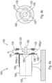
- Figure 4 shows the sensor arrangement 105 from Fig.1 again in connection with the machine 100 in a) side view and b) the carrier 135 in front view.
- Fig.4 shows a variant in which a total of four flow elements are mounted on the carrier 135 125 are present. These extend in the circumferential direction to the rotation axis 155.
- the carrier 135 has a central hole for mounting on the rotor 185 or the corresponding shaft of the motor or machine 100.
- the flux element 125 reduces the inductance La-i of the coil 160a-i when it is "above” it or slides over it.
- the flux element can also be referred to here as a "copper activator" in the periphery of the non-conductive disk or the carrier 135.
- a support part 190 for the flat coils 60a-i or a circuit board 195, symbolically indicated here, on which they are mounted, is attached to the stator 180 or a motor housing, for example with screws or rivets.
- the motor or machine 100 is attached to a solid mounting base via a mounting column (not explained in more detail).
- Fig. 5a shows an alternative sensor arrangement 105.
- the surface 120 is a straight circular cylinder shell around the rotation axis 155.
- the flat coils 160a-i are also sections of the circular cylinder shell.
- the coils are basically as in Fig.1 shaped, ie in one plane “trapezoidal", but “rolled up” or “bent” on the circular cylinder shell.
- three identical coil groups are arranged, each with three flat coils (as in Fig.1 ) is present.
- Each of the coil groups extends again by rotation angle ranges Wa-c of 120° each in the circumferential direction around the rotation axis 155.
- the widths B (now measured in the axial direction) of the flat coils 160a-i increase or decrease in the circumferential direction in a strictly monotonous manner.
- the flux element 125 is accommodated in a cylindrical carrier 135 which is firmly attached to the rotor 185.
- the flat coils 160a-i together occupy a vertical circular cylinder shell.
- Figure 5b shows another variant of a sensor arrangement 125, in principle according to Fig. 5a
- the flux element 125 is designed with a circumferentially sinusoidal or sinusoidally changing property 175, namely its width B.
- the flat coils 160a-i each have a constant width B here.
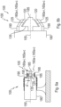
- Figure 6a shows (optional, therefore not specifically shown) the sensor arrangement 105 from Fig. 5a,b , installed in the machine 100 according to Fig. 4a .
- the carrier 135 is a thick PVC/plastic/polymer ring for attaching the activator or flow element 125 on the motor shaft or the rotor 180.
- the inductive sensors or flat coils 160a-i are multi-turn/multi-level flat coils.
- a distance d denotes in Figures 4a and 6a the distance between sensors (flat coils 160) and activator (flux element 125).
- Figure 6b shows an alternative shape, namely a cone shape for flat coils 160, flux elements 125, carrier 135 and support part 190.
- the embodiment is a cone shape and thus an "intermediate form" between the "disk shape” ( Fig.1 ) and the “cylindrical shape” ( Fig.5 Otherwise, the explanations above apply accordingly.
- Figure 7 shows an example of a coil group 165a with only two flat coils 160a,b, which are suitable for the embodiments of the Figures 5a, b
- the widths B in the axial direction
- the widths B are measured in opposite directions, falling and rising in a strictly monotonous manner in the circumferential direction.
- a first level of the flat coils with a large number of turns can be seen.
- Further levels are connected here invisibly "under" the paper level.
- Figure 8 shows in a plan view in the direction of the axis of rotation 155 an alternative embodiment of a sensor arrangement, in principle corresponding Fig.1
- a flat sensor arrangement made up of six square coils and a rhombus-shaped flux element was "bent” or “unrolled” into a circular shape.
- Each of the six coil groups 165a-f has a single flat coil 160a-f.
- the corresponding flat output sensor arrangement is made up of Figure 1 in the document " AK Palit, 'Frequency Response Modeling of Inductive Position Sensor with Finite Element Tools', Proceedings of the 2014 COMSOL Conference in Cambridge, https://www.comsol.com/ paper/ download/ 199331/ palit_paper.pdf, accessed on December 5, 2018 " known.
Landscapes
- Physics & Mathematics (AREA)
- General Physics & Mathematics (AREA)
- Transmission And Conversion Of Sensor Element Output (AREA)
Claims (12)
- Ensemble formant capteur (105) destiné à détecter un angle de rotation (D) d'un élément de flux (125), qui peut tourner autour d'un axe de rotation (155) le long d'une trajectoire circulaire (130), ledit ensemble formant capteur comprenant- au moins un élément de flux (125), et- au moins un groupe de bobines (165a-c) comportant chacune au moins une bobine plate (160a-i), au moins deux bobines plates (16a-i) étant prévues,- les bobines plates (160a-i) s'étendant chacune le long d'une surface (120) qui entoure concentriquement l'axe de rotation (155),- la surface (120) s'étendant parallèlement le long de la trajectoire circulaire (130), et toutes les bobines plates (160a-i) d'un groupe de bobines (165a-c) s'étendant sur la même plage d'angle de rotation (Wa-c),- les bobines plates (160a-i) étant formées de manière à ce qu'une inductance actuelle (La-i) de chaque bobine plate (160a-i) dépende de l'angle de rotation actuel (D) de l'élément de flux (125),- un dispositif d'évaluation (145), qui est conçu pour déterminer, pour chacune des bobines plates (160ai), l'inductance actuelle (La-i) et un angle de rotation individuel actuel (Ea-i) de l'élément de flux (125) sur la base de l'inductance (La-i) déterminée de la bobine plate respective (160a-i) et pour fournir l'angle de rotation (D) de l'élément de flux (125) sur la base d'au moins deux angles de rotation individuels (Ea-i) en coïncidence,- au moins deux des bobines plates (160a-i) étant formées de manière à ce que la taille actuelle (A) d'une zone (170) des bobines plates (160a-i) actuellement couverte par l'élément de flux (125) dépende de l'angle de rotation actuel (D) de l'élément de flux (125),- la plage d'angle de rotation (Wa-c) d'au moins un des groupes de bobines (165a-c) s'étendant entre un angle initial (WS) et un angle final (WE) et une largeur (B) d'une telle première bobine plate (160a-i) du groupe de bobines (165a-c) diminuant transversalement à la trajectoire circulaire (130) à partir de l'angle initial (WS) et une largeur (B) d'une telle deuxième bobine plate (160a-i) du groupe de bobines (165a-c) augmentant à partir de l'angle initial (WS),- au moins un des groupes de bobines (165a-c) contenant au moins trois bobines plates (160a-i), une deuxième bobine plate (160a-i) étant située entre la première (160a-i) et la troisième (160a-i) bobine plate dans une direction transversale à la trajectoire circulaire (130).
- Ensemble formant capteur (105) selon la revendication 1,
caractérisé en ce que l'ensemble formant capteur (105) contient au moins deux groupes de bobines (165a, b) qui s'étendent dans la direction circonférentielle sur différentes plages d'angle de rotation (Wa-c). - Ensemble formant capteur (105) selon la revendication 2,
caractérisé en ce qu'au moins deux des plages d'angle de rotation (Wa, b) ne se chevauchent pas et se raccordent l'une à l'autre de manière jointive. - Ensemble formant capteur (105) selon l'une des revendications précédentes,
caractérisé en ce que la surface (120) est plane et s'étend transversalement à l'axe de rotation (155) ou la surface (120) a une forme conique ou une forme de cône à base circulaire ou une forme de surface latérale d'un cylindre à base circulaire autour de l'axe de rotation (155). - Ensemble formant capteur (105) selon l'une des revendications précédentes,
caractérisé en ce que l'élément de flux (125) présente une propriété sinusoïdale (175) le long de la trajectoire circulaire (130). - Ensemble formant capteur (105) selon l'une des revendications précédentes,
caractérisé en ce que les bobines plates (160a-i) d'au moins un des groupes de bobines (165a-c) occupent conjointement un segment d'anneau circulaire ou une enveloppe conique ou une enveloppe cylindrique circulaire perpendiculaire de la surface (120). - Ensemble formant capteur (105) selon l'une des revendications précédentes,
caractérisé en ce que les largeurs (B) des bobines plates (160a-i) s'étendent de manière strictement monotone transversalement à la trajectoire circulaire (130) le long de la trajectoire circulaire (130). - Ensemble formant capteur (105) selon l'une des revendications précédentes, caractérisé en ce qu'au moins une des bobines plates (160a-i) présente plusieurs niveaux.
- Ensemble formant capteur (105) selon l'une des revendications précédentes, caractérisé en ce que l'élément de flux (125) contient un élément électriquement conducteur qui s'étend parallèlement à la surface (120).
- Machine électrique (100) comprenant un stator (180) et un rotor (185) qui peut tourner sur un axe de rotation (155) par rapport au stator (180) et l'ensemble formant capteur (105) selon l'une des revendications précédentes, l'axe de rotation (155) de l'ensemble formant capteur (105) étant celui de la machine (100) et l'élément de flux (125) étant accouplé solidairement en rotation au rotor (185) et les groupes de bobines (165a-c) étant accouplés solidairement en rotation au stator (180) ou vice versa.
- Machine (100) selon la revendication 10, caractérisée en ce que l'élément de flux (125) est monté sur un support non conducteur (135) fixé au rotor (185) .
- Procédé de détection d'un angle de rotation (D) d'un élément de flux (125) d'un ensemble formant capteur (105) selon l'une des revendications 1 à 9 ou d'une machine (100) selon l'une des revendications 10 à 11, procédé dans lequel :- l'inductance actuelle (La-i) est déterminée pour chacune des bobines plates (160a-i), et- un angle de rotation individuel respectif actuel (Ea-i) de l'élément de flux (125) est déterminé sur la base de l'inductance déterminée (La-i) de la bobine plate respective (160a-i), et- l'angle de rotation (D) de l'élément de flux (125) est obtenu sur la base d'au moins deux angles de rotation individuels (Ea-i) en coïncidence,- l'ensemble formant capteur (105) contenant au moins trois bobines plates (160a-i) dans lesquelles une bobine plate défectueuse (160a-i) du groupe de bobines (165a-c) est détectée si un angle de rotation individuel (Ea-i) déterminé sur la base de son inductance (La-i) diffère des angles de rotation individuels correspondants (Ea-i) d'autres bobines plates (160a-i).
Applications Claiming Priority (2)
| Application Number | Priority Date | Filing Date | Title |
|---|---|---|---|
| DE102018221317.8A DE102018221317A1 (de) | 2018-12-10 | 2018-12-10 | Induktive Drehwinkelerfassung |
| PCT/EP2019/084079 WO2020120337A1 (fr) | 2018-12-10 | 2019-12-06 | Détection inductive d'angle de rotation |
Publications (2)
| Publication Number | Publication Date |
|---|---|
| EP3894792A1 EP3894792A1 (fr) | 2021-10-20 |
| EP3894792B1 true EP3894792B1 (fr) | 2024-08-28 |
Family
ID=68944381
Family Applications (1)
| Application Number | Title | Priority Date | Filing Date |
|---|---|---|---|
| EP19823778.6A Active EP3894792B1 (fr) | 2018-12-10 | 2019-12-06 | Détection inductive d'un angle de rotation |
Country Status (5)
| Country | Link |
|---|---|
| US (1) | US20210333128A1 (fr) |
| EP (1) | EP3894792B1 (fr) |
| CN (1) | CN113196013B (fr) |
| DE (1) | DE102018221317A1 (fr) |
| WO (1) | WO2020120337A1 (fr) |
Citations (1)
| Publication number | Priority date | Publication date | Assignee | Title |
|---|---|---|---|---|
| DE10044839A1 (de) * | 1999-09-27 | 2001-04-05 | Siemens Ag | Induktiver Positionssensor |
Family Cites Families (21)
| Publication number | Priority date | Publication date | Assignee | Title |
|---|---|---|---|---|
| DE2617624C2 (de) * | 1976-04-22 | 1986-04-03 | Metrawatt GmbH, 8500 Nürnberg | Linearisierung für induktiven Stellungsgeber |
| US4697144A (en) * | 1984-04-19 | 1987-09-29 | Verify Electronics Limited | Position sensing apparatus |
| US6522130B1 (en) * | 1998-07-20 | 2003-02-18 | Uqm Technologies, Inc. | Accurate rotor position sensor and method using magnet and sensors mounted adjacent to the magnet and motor |
| DE60007270T2 (de) * | 2000-02-01 | 2004-09-02 | Cherry Gmbh | Position sensor |
| DE10025661A1 (de) * | 2000-05-24 | 2001-12-06 | Balluff Gebhard Feinmech | Wegmeßsystem |
| US6443020B1 (en) * | 2000-09-15 | 2002-09-03 | Delphi Technologies, Inc. | Steering column differential angle position sensor |
| DE10352351B4 (de) * | 2003-05-07 | 2006-03-09 | Ifm Electronic Gmbh | Verfahren zur Bestimmung der Position eines Beeinflussungselements mit einem induktiven Positionssensor |
| ATE398765T1 (de) * | 2004-03-01 | 2008-07-15 | Sagentia Ltd | Positionssensor |
| US7449878B2 (en) * | 2005-06-27 | 2008-11-11 | Ksr Technologies Co. | Linear and rotational inductive position sensor |
| DE102006031139A1 (de) * | 2006-07-03 | 2008-01-10 | Rudolf Schubach | Vorrichtung zum berührungslosen Messen der absoluten linearen Position mit planaren Spulen |
| DE102006055409A1 (de) * | 2006-11-22 | 2008-05-29 | Ab Elektronik Gmbh | Induktiver Sensor zur Erfassung von zwei Koppelelementen |
| DE102007015195A1 (de) * | 2007-03-29 | 2008-10-09 | Cherry Gmbh | Drehwinkelsensor oder Längensensor |
| US20080284554A1 (en) * | 2007-05-14 | 2008-11-20 | Thaddeus Schroeder | Compact robust linear position sensor |
| CN202692976U (zh) * | 2012-05-31 | 2013-01-23 | 西北工业大学 | 一种舵机舵面角位置传感器冗余装置 |
| DE102012014493B4 (de) * | 2012-07-23 | 2020-07-09 | Epro Gmbh | Verfahren und Vorrichtung zur redundanten Erkennung einer Drehrichtung |
| GB2506698A (en) * | 2012-10-02 | 2014-04-09 | Mark Anthony Howard | Detector to measure the relative position of bodies |
| DE102014220454A1 (de) * | 2014-10-09 | 2016-04-14 | Robert Bosch Gmbh | Sensoranordnung zur berührungslosen Erfassung von Drehwinkeln an einem rotierenden Bauteil |
| WO2016119814A1 (fr) * | 2015-01-26 | 2016-08-04 | Abb Schweiz Ag | Résolveur destiné à un servomoteur |
| DE102015220617A1 (de) * | 2015-10-22 | 2017-04-27 | Robert Bosch Gmbh | Drehwinkelsensor |
| WO2018237402A1 (fr) * | 2017-06-22 | 2018-12-27 | China Automotive Systems, Inc. | Capteur de couple et d'angle |
| DE102017211493A1 (de) * | 2017-07-06 | 2019-01-10 | Robert Bosch Gmbh | Drehwinkelsensoranordnung, LiDAR-System und Arbeitsvorrichtung |
-
2018
- 2018-12-10 DE DE102018221317.8A patent/DE102018221317A1/de not_active Withdrawn
-
2019
- 2019-12-06 CN CN201980081702.8A patent/CN113196013B/zh active Active
- 2019-12-06 US US17/312,591 patent/US20210333128A1/en not_active Abandoned
- 2019-12-06 EP EP19823778.6A patent/EP3894792B1/fr active Active
- 2019-12-06 WO PCT/EP2019/084079 patent/WO2020120337A1/fr not_active Ceased
Patent Citations (1)
| Publication number | Priority date | Publication date | Assignee | Title |
|---|---|---|---|---|
| DE10044839A1 (de) * | 1999-09-27 | 2001-04-05 | Siemens Ag | Induktiver Positionssensor |
Also Published As
| Publication number | Publication date |
|---|---|
| CN113196013B (zh) | 2024-03-01 |
| US20210333128A1 (en) | 2021-10-28 |
| WO2020120337A1 (fr) | 2020-06-18 |
| DE102018221317A1 (de) | 2020-06-10 |
| CN113196013A (zh) | 2021-07-30 |
| EP3894792A1 (fr) | 2021-10-20 |
Similar Documents
| Publication | Publication Date | Title |
|---|---|---|
| EP4170289B1 (fr) | Dispositif inductif de mesure d'angle | |
| DE69810504T2 (de) | Positionsgeber | |
| EP2105713B1 (fr) | Appareil de mesure de position et son procédé de fonctionnement | |
| EP2265902B1 (fr) | Détecteur d'angle de rotation inductif et procédé d'exploitation d'un détecteur d'angle de rotation inductif | |
| EP1906153B1 (fr) | Encodeur et son procédé de fonctionnement | |
| EP3355032B1 (fr) | Capteur de mesure de position | |
| EP2743649B1 (fr) | Dispositif de mesure de position inductif | |
| EP2711671B1 (fr) | Appareil de mesure de position et son procédé de fonctionnement | |
| DE102013202078B4 (de) | Positionssensor | |
| EP3555571B1 (fr) | Système de capteur pour déterminer au moins une propriété de rotation d'au moins un élément rotatif tournant autour d'au moins un axe de rotation | |
| EP3534121B1 (fr) | Capteur de rotation multitour | |
| EP1475604A2 (fr) | Capteur d'angle inductif | |
| EP3961158B1 (fr) | Unité de balayage et dispositif inductif de mesure de position pourvu d'une telle unité de balayage | |
| EP3365634A1 (fr) | Capteur d'angle de rotation | |
| DE102012200195A1 (de) | Positionssensor | |
| DE102018113379A1 (de) | Drehwinkelerfassungseinrichtung, Drehwinkelerfassungsanordnung, Leistungserfassungsvorrichtung und Verfahren zur Drehwinkelerfassung | |
| DE102015202732A1 (de) | Sensoranordnung zur Erfassung von Drehwinkeln an einem rotierenden Bauteil in einem Fahrzeug | |
| DE102020209601A1 (de) | Erfassungsvorrichtung für einen Lagegeber und Erfassungssystem mit einer solchen Erfassungsvorrichtung | |
| EP4273507A1 (fr) | Élément de détection et dispositif inductif de mesure de position pourvu dudit élément palpeur | |
| WO1992014121A1 (fr) | Dispositif de mesure de mouvement angulaire | |
| DE102020205202A1 (de) | Induktive Winkelmesseinrichtung | |
| WO2021043644A1 (fr) | Ensemble capteur permettant la détection d'un angle de rotation d'un élément d'écoulement | |
| DE102018221317A1 (de) | Induktive Drehwinkelerfassung | |
| DE102016224854A1 (de) | Sensorsystem zur Bestimmung mindestens einer Rotationseigenschaft eines um mindestens eine Rotationsachse rotierenden Elements | |
| EP4230967A1 (fr) | Élément palpeur et dispositif inductif de mesure de position pourvu dudit élément palpeur |
Legal Events
| Date | Code | Title | Description |
|---|---|---|---|
| STAA | Information on the status of an ep patent application or granted ep patent |
Free format text: STATUS: UNKNOWN |
|
| STAA | Information on the status of an ep patent application or granted ep patent |
Free format text: STATUS: THE INTERNATIONAL PUBLICATION HAS BEEN MADE |
|
| PUAI | Public reference made under article 153(3) epc to a published international application that has entered the european phase |
Free format text: ORIGINAL CODE: 0009012 |
|
| STAA | Information on the status of an ep patent application or granted ep patent |
Free format text: STATUS: REQUEST FOR EXAMINATION WAS MADE |
|
| 17P | Request for examination filed |
Effective date: 20210611 |
|
| AK | Designated contracting states |
Kind code of ref document: A1 Designated state(s): AL AT BE BG CH CY CZ DE DK EE ES FI FR GB GR HR HU IE IS IT LI LT LU LV MC MK MT NL NO PL PT RO RS SE SI SK SM TR |
|
| DAV | Request for validation of the european patent (deleted) | ||
| DAX | Request for extension of the european patent (deleted) | ||
| STAA | Information on the status of an ep patent application or granted ep patent |
Free format text: STATUS: EXAMINATION IS IN PROGRESS |
|
| 17Q | First examination report despatched |
Effective date: 20230327 |
|
| GRAP | Despatch of communication of intention to grant a patent |
Free format text: ORIGINAL CODE: EPIDOSNIGR1 |
|
| STAA | Information on the status of an ep patent application or granted ep patent |
Free format text: STATUS: GRANT OF PATENT IS INTENDED |
|
| INTG | Intention to grant announced |
Effective date: 20240404 |
|
| GRAS | Grant fee paid |
Free format text: ORIGINAL CODE: EPIDOSNIGR3 |
|
| GRAA | (expected) grant |
Free format text: ORIGINAL CODE: 0009210 |
|
| STAA | Information on the status of an ep patent application or granted ep patent |
Free format text: STATUS: THE PATENT HAS BEEN GRANTED |
|
| AK | Designated contracting states |
Kind code of ref document: B1 Designated state(s): AL AT BE BG CH CY CZ DE DK EE ES FI FR GB GR HR HU IE IS IT LI LT LU LV MC MK MT NL NO PL PT RO RS SE SI SK SM TR |
|
| REG | Reference to a national code |
Ref country code: CH Ref legal event code: EP |
|
| REG | Reference to a national code |
Ref country code: DE Ref legal event code: R096 Ref document number: 502019012015 Country of ref document: DE |
|
| REG | Reference to a national code |
Ref country code: IE Ref legal event code: FG4D Free format text: LANGUAGE OF EP DOCUMENT: GERMAN |
|
| REG | Reference to a national code |
Ref country code: LT Ref legal event code: MG9D |
|
| PG25 | Lapsed in a contracting state [announced via postgrant information from national office to epo] |
Ref country code: NO Free format text: LAPSE BECAUSE OF FAILURE TO SUBMIT A TRANSLATION OF THE DESCRIPTION OR TO PAY THE FEE WITHIN THE PRESCRIBED TIME-LIMIT Effective date: 20241128 |
|
| PG25 | Lapsed in a contracting state [announced via postgrant information from national office to epo] |
Ref country code: NL Free format text: LAPSE BECAUSE OF FAILURE TO SUBMIT A TRANSLATION OF THE DESCRIPTION OR TO PAY THE FEE WITHIN THE PRESCRIBED TIME-LIMIT Effective date: 20240828 Ref country code: FI Free format text: LAPSE BECAUSE OF FAILURE TO SUBMIT A TRANSLATION OF THE DESCRIPTION OR TO PAY THE FEE WITHIN THE PRESCRIBED TIME-LIMIT Effective date: 20240828 Ref country code: GR Free format text: LAPSE BECAUSE OF FAILURE TO SUBMIT A TRANSLATION OF THE DESCRIPTION OR TO PAY THE FEE WITHIN THE PRESCRIBED TIME-LIMIT Effective date: 20241129 Ref country code: PL Free format text: LAPSE BECAUSE OF FAILURE TO SUBMIT A TRANSLATION OF THE DESCRIPTION OR TO PAY THE FEE WITHIN THE PRESCRIBED TIME-LIMIT Effective date: 20240828 Ref country code: PT Free format text: LAPSE BECAUSE OF FAILURE TO SUBMIT A TRANSLATION OF THE DESCRIPTION OR TO PAY THE FEE WITHIN THE PRESCRIBED TIME-LIMIT Effective date: 20241230 |
|
| PG25 | Lapsed in a contracting state [announced via postgrant information from national office to epo] |
Ref country code: BG Free format text: LAPSE BECAUSE OF FAILURE TO SUBMIT A TRANSLATION OF THE DESCRIPTION OR TO PAY THE FEE WITHIN THE PRESCRIBED TIME-LIMIT Effective date: 20240828 |
|
| PG25 | Lapsed in a contracting state [announced via postgrant information from national office to epo] |
Ref country code: LV Free format text: LAPSE BECAUSE OF FAILURE TO SUBMIT A TRANSLATION OF THE DESCRIPTION OR TO PAY THE FEE WITHIN THE PRESCRIBED TIME-LIMIT Effective date: 20240828 |
|
| REG | Reference to a national code |
Ref country code: NL Ref legal event code: MP Effective date: 20240828 |
|
| PG25 | Lapsed in a contracting state [announced via postgrant information from national office to epo] |
Ref country code: IS Free format text: LAPSE BECAUSE OF FAILURE TO SUBMIT A TRANSLATION OF THE DESCRIPTION OR TO PAY THE FEE WITHIN THE PRESCRIBED TIME-LIMIT Effective date: 20241228 |
|
| PG25 | Lapsed in a contracting state [announced via postgrant information from national office to epo] |
Ref country code: HR Free format text: LAPSE BECAUSE OF FAILURE TO SUBMIT A TRANSLATION OF THE DESCRIPTION OR TO PAY THE FEE WITHIN THE PRESCRIBED TIME-LIMIT Effective date: 20240828 |
|
| PG25 | Lapsed in a contracting state [announced via postgrant information from national office to epo] |
Ref country code: ES Free format text: LAPSE BECAUSE OF FAILURE TO SUBMIT A TRANSLATION OF THE DESCRIPTION OR TO PAY THE FEE WITHIN THE PRESCRIBED TIME-LIMIT Effective date: 20240828 Ref country code: RS Free format text: LAPSE BECAUSE OF FAILURE TO SUBMIT A TRANSLATION OF THE DESCRIPTION OR TO PAY THE FEE WITHIN THE PRESCRIBED TIME-LIMIT Effective date: 20241128 |
|
| PG25 | Lapsed in a contracting state [announced via postgrant information from national office to epo] |
Ref country code: RS Free format text: LAPSE BECAUSE OF FAILURE TO SUBMIT A TRANSLATION OF THE DESCRIPTION OR TO PAY THE FEE WITHIN THE PRESCRIBED TIME-LIMIT Effective date: 20241128 Ref country code: PT Free format text: LAPSE BECAUSE OF FAILURE TO SUBMIT A TRANSLATION OF THE DESCRIPTION OR TO PAY THE FEE WITHIN THE PRESCRIBED TIME-LIMIT Effective date: 20241230 Ref country code: PL Free format text: LAPSE BECAUSE OF FAILURE TO SUBMIT A TRANSLATION OF THE DESCRIPTION OR TO PAY THE FEE WITHIN THE PRESCRIBED TIME-LIMIT Effective date: 20240828 Ref country code: NO Free format text: LAPSE BECAUSE OF FAILURE TO SUBMIT A TRANSLATION OF THE DESCRIPTION OR TO PAY THE FEE WITHIN THE PRESCRIBED TIME-LIMIT Effective date: 20241128 Ref country code: NL Free format text: LAPSE BECAUSE OF FAILURE TO SUBMIT A TRANSLATION OF THE DESCRIPTION OR TO PAY THE FEE WITHIN THE PRESCRIBED TIME-LIMIT Effective date: 20240828 Ref country code: LV Free format text: LAPSE BECAUSE OF FAILURE TO SUBMIT A TRANSLATION OF THE DESCRIPTION OR TO PAY THE FEE WITHIN THE PRESCRIBED TIME-LIMIT Effective date: 20240828 Ref country code: IS Free format text: LAPSE BECAUSE OF FAILURE TO SUBMIT A TRANSLATION OF THE DESCRIPTION OR TO PAY THE FEE WITHIN THE PRESCRIBED TIME-LIMIT Effective date: 20241228 Ref country code: HR Free format text: LAPSE BECAUSE OF FAILURE TO SUBMIT A TRANSLATION OF THE DESCRIPTION OR TO PAY THE FEE WITHIN THE PRESCRIBED TIME-LIMIT Effective date: 20240828 Ref country code: GR Free format text: LAPSE BECAUSE OF FAILURE TO SUBMIT A TRANSLATION OF THE DESCRIPTION OR TO PAY THE FEE WITHIN THE PRESCRIBED TIME-LIMIT Effective date: 20241129 Ref country code: FI Free format text: LAPSE BECAUSE OF FAILURE TO SUBMIT A TRANSLATION OF THE DESCRIPTION OR TO PAY THE FEE WITHIN THE PRESCRIBED TIME-LIMIT Effective date: 20240828 Ref country code: ES Free format text: LAPSE BECAUSE OF FAILURE TO SUBMIT A TRANSLATION OF THE DESCRIPTION OR TO PAY THE FEE WITHIN THE PRESCRIBED TIME-LIMIT Effective date: 20240828 Ref country code: BG Free format text: LAPSE BECAUSE OF FAILURE TO SUBMIT A TRANSLATION OF THE DESCRIPTION OR TO PAY THE FEE WITHIN THE PRESCRIBED TIME-LIMIT Effective date: 20240828 |
|
| PG25 | Lapsed in a contracting state [announced via postgrant information from national office to epo] |
Ref country code: DK Free format text: LAPSE BECAUSE OF FAILURE TO SUBMIT A TRANSLATION OF THE DESCRIPTION OR TO PAY THE FEE WITHIN THE PRESCRIBED TIME-LIMIT Effective date: 20240828 Ref country code: RO Free format text: LAPSE BECAUSE OF FAILURE TO SUBMIT A TRANSLATION OF THE DESCRIPTION OR TO PAY THE FEE WITHIN THE PRESCRIBED TIME-LIMIT Effective date: 20240828 Ref country code: SM Free format text: LAPSE BECAUSE OF FAILURE TO SUBMIT A TRANSLATION OF THE DESCRIPTION OR TO PAY THE FEE WITHIN THE PRESCRIBED TIME-LIMIT Effective date: 20240828 |
|
| PG25 | Lapsed in a contracting state [announced via postgrant information from national office to epo] |
Ref country code: EE Free format text: LAPSE BECAUSE OF FAILURE TO SUBMIT A TRANSLATION OF THE DESCRIPTION OR TO PAY THE FEE WITHIN THE PRESCRIBED TIME-LIMIT Effective date: 20240828 |
|
| PG25 | Lapsed in a contracting state [announced via postgrant information from national office to epo] |
Ref country code: CZ Free format text: LAPSE BECAUSE OF FAILURE TO SUBMIT A TRANSLATION OF THE DESCRIPTION OR TO PAY THE FEE WITHIN THE PRESCRIBED TIME-LIMIT Effective date: 20240828 |
|
| PG25 | Lapsed in a contracting state [announced via postgrant information from national office to epo] |
Ref country code: SK Free format text: LAPSE BECAUSE OF FAILURE TO SUBMIT A TRANSLATION OF THE DESCRIPTION OR TO PAY THE FEE WITHIN THE PRESCRIBED TIME-LIMIT Effective date: 20240828 Ref country code: IT Free format text: LAPSE BECAUSE OF FAILURE TO SUBMIT A TRANSLATION OF THE DESCRIPTION OR TO PAY THE FEE WITHIN THE PRESCRIBED TIME-LIMIT Effective date: 20240828 |
|
| REG | Reference to a national code |
Ref country code: DE Ref legal event code: R097 Ref document number: 502019012015 Country of ref document: DE |
|
| PLBE | No opposition filed within time limit |
Free format text: ORIGINAL CODE: 0009261 |
|
| STAA | Information on the status of an ep patent application or granted ep patent |
Free format text: STATUS: NO OPPOSITION FILED WITHIN TIME LIMIT |
|
| PG25 | Lapsed in a contracting state [announced via postgrant information from national office to epo] |
Ref country code: MC Free format text: LAPSE BECAUSE OF FAILURE TO SUBMIT A TRANSLATION OF THE DESCRIPTION OR TO PAY THE FEE WITHIN THE PRESCRIBED TIME-LIMIT Effective date: 20240828 |
|
| REG | Reference to a national code |
Ref country code: CH Ref legal event code: PL |
|
| 26N | No opposition filed |
Effective date: 20250530 |
|
| PG25 | Lapsed in a contracting state [announced via postgrant information from national office to epo] |
Ref country code: LU Free format text: LAPSE BECAUSE OF NON-PAYMENT OF DUE FEES Effective date: 20241206 |
|
| GBPC | Gb: european patent ceased through non-payment of renewal fee |
Effective date: 20241206 |
|
| PG25 | Lapsed in a contracting state [announced via postgrant information from national office to epo] |
Ref country code: SE Free format text: LAPSE BECAUSE OF FAILURE TO SUBMIT A TRANSLATION OF THE DESCRIPTION OR TO PAY THE FEE WITHIN THE PRESCRIBED TIME-LIMIT Effective date: 20240828 |
|
| REG | Reference to a national code |
Ref country code: BE Ref legal event code: MM Effective date: 20241231 |
|
| PG25 | Lapsed in a contracting state [announced via postgrant information from national office to epo] |
Ref country code: GB Free format text: LAPSE BECAUSE OF NON-PAYMENT OF DUE FEES Effective date: 20241206 Ref country code: BE Free format text: LAPSE BECAUSE OF NON-PAYMENT OF DUE FEES Effective date: 20241231 |
|
| PG25 | Lapsed in a contracting state [announced via postgrant information from national office to epo] |
Ref country code: FR Free format text: LAPSE BECAUSE OF NON-PAYMENT OF DUE FEES Effective date: 20241231 |
|
| PG25 | Lapsed in a contracting state [announced via postgrant information from national office to epo] |
Ref country code: CH Free format text: LAPSE BECAUSE OF NON-PAYMENT OF DUE FEES Effective date: 20241231 |
|
| PG25 | Lapsed in a contracting state [announced via postgrant information from national office to epo] |
Ref country code: IE Free format text: LAPSE BECAUSE OF NON-PAYMENT OF DUE FEES Effective date: 20241206 |
|
| PGFP | Annual fee paid to national office [announced via postgrant information from national office to epo] |
Ref country code: DE Payment date: 20250930 Year of fee payment: 7 |
|
| REG | Reference to a national code |
Ref country code: AT Ref legal event code: MM01 Ref document number: 1718395 Country of ref document: AT Kind code of ref document: T Effective date: 20241206 |
|
| PG25 | Lapsed in a contracting state [announced via postgrant information from national office to epo] |
Ref country code: CY Free format text: LAPSE BECAUSE OF FAILURE TO SUBMIT A TRANSLATION OF THE DESCRIPTION OR TO PAY THE FEE WITHIN THE PRESCRIBED TIME-LIMIT; INVALID AB INITIO Effective date: 20191206 |
|
| PG25 | Lapsed in a contracting state [announced via postgrant information from national office to epo] |
Ref country code: AT Free format text: LAPSE BECAUSE OF NON-PAYMENT OF DUE FEES Effective date: 20241206 |
|
| PG25 | Lapsed in a contracting state [announced via postgrant information from national office to epo] |
Ref country code: TR Free format text: LAPSE BECAUSE OF FAILURE TO SUBMIT A TRANSLATION OF THE DESCRIPTION OR TO PAY THE FEE WITHIN THE PRESCRIBED TIME-LIMIT Effective date: 20240828 |
|
| PG25 | Lapsed in a contracting state [announced via postgrant information from national office to epo] |
Ref country code: HU Free format text: LAPSE BECAUSE OF FAILURE TO SUBMIT A TRANSLATION OF THE DESCRIPTION OR TO PAY THE FEE WITHIN THE PRESCRIBED TIME-LIMIT; INVALID AB INITIO Effective date: 20191206 |
|
| PG25 | Lapsed in a contracting state [announced via postgrant information from national office to epo] |
Ref country code: SI Free format text: LAPSE BECAUSE OF FAILURE TO SUBMIT A TRANSLATION OF THE DESCRIPTION OR TO PAY THE FEE WITHIN THE PRESCRIBED TIME-LIMIT Effective date: 20240828 |
|
| PG25 | Lapsed in a contracting state [announced via postgrant information from national office to epo] |
Ref country code: LT Free format text: LAPSE BECAUSE OF FAILURE TO SUBMIT A TRANSLATION OF THE DESCRIPTION OR TO PAY THE FEE WITHIN THE PRESCRIBED TIME-LIMIT Effective date: 20240828 |