EP3895526A1 - Melkvorrichtung, melksystem und verfahren hierfür - Google Patents
Melkvorrichtung, melksystem und verfahren hierfür Download PDFInfo
- Publication number
- EP3895526A1 EP3895526A1 EP21168961.7A EP21168961A EP3895526A1 EP 3895526 A1 EP3895526 A1 EP 3895526A1 EP 21168961 A EP21168961 A EP 21168961A EP 3895526 A1 EP3895526 A1 EP 3895526A1
- Authority
- EP
- European Patent Office
- Prior art keywords
- milking
- ground surface
- teat cups
- milking device
- animal
- Prior art date
- Legal status (The legal status is an assumption and is not a legal conclusion. Google has not performed a legal analysis and makes no representation as to the accuracy of the status listed.)
- Granted
Links
Images




Classifications
-
- A—HUMAN NECESSITIES
- A01—AGRICULTURE; FORESTRY; ANIMAL HUSBANDRY; HUNTING; TRAPPING; FISHING
- A01J—MANUFACTURE OF DAIRY PRODUCTS
- A01J5/00—Milking machines or devices
- A01J5/017—Automatic attaching or detaching of clusters
- A01J5/0175—Attaching of clusters
-
- A—HUMAN NECESSITIES
- A01—AGRICULTURE; FORESTRY; ANIMAL HUSBANDRY; HUNTING; TRAPPING; FISHING
- A01J—MANUFACTURE OF DAIRY PRODUCTS
- A01J5/00—Milking machines or devices
- A01J5/017—Automatic attaching or detaching of clusters
-
- A—HUMAN NECESSITIES
- A01—AGRICULTURE; FORESTRY; ANIMAL HUSBANDRY; HUNTING; TRAPPING; FISHING
- A01K—ANIMAL HUSBANDRY; AVICULTURE; APICULTURE; PISCICULTURE; FISHING; REARING OR BREEDING ANIMALS, NOT OTHERWISE PROVIDED FOR; NEW BREEDS OF ANIMALS
- A01K1/00—Housing animals; Equipment therefor
- A01K1/12—Milking stations
Definitions
- the present invention relates to a milking device for milking animals.
- the invention further relates to a milking system and milking parlour comprising a milking device and a method for milking an animal.
- Milking devices are known in practice.
- the known milking devices comprise a milking claw to which teat cups are connected.
- the milker In order to milk the animal to be milked the milker must hold the milking claw with one hand and place the teat cups on the teats of the animal to be milked one by one with the other hand.
- a drawback of the known milking devices is that many operations are required on the part of the milker before the teat cups are positioned on the teats of the animal to be milked. This has the result that the output of a milker is relatively low.
- the known milking devices further have the drawback that the operations are carried out by the milker in an ergonomically adverse posture.
- milking devices wherein teat cups are moved upward from a position under the animal to be milked. These milking devices are positioned under the ground surface, for instance a cow stall. The milking device can be moved from a position under the animal toward the udder through an opening in the ground surface, after which a milker can attach the teat cups to the teats.
- a drawback of such known milking devices is that dirt, such as for instance manure, can find its way into the teat cups through the opening in the ground surface. This reduces hygiene and thereby increases the chance of infections, for instance of the udders.
- a milking device for milking animals, comprising:
- the milking device is configured to arrange teat cups from a position below the animal to be milked, there is no need for a robot arm with a lateral movement to attach the teat cups to the teats, this resulting in a more peaceful environment and so less stress for the animal. This increases animal welfare and generally also enhances the quality of the milk.
- a further advantage is that, when the milking device is in the milking state, a milker can connect two teat cups to the teats at the same time in simple manner. This increases the convenience of use during milking. Alternatively or additionally, this also increases the speed with which the teat cups can be connected, whereby more animals can be milked per unit of time.
- the milking state is the state wherein the teat cups are positioned at least partially above the ground surface, such that the teat cups are ready to be placed on the teats of the animal to be milked by a milker.
- the second stroke ensures that there is enough slack in the milk hoses to move the teat cups from the teat cup carrier to the teats and place them thereon.
- the cylinder is preferably also configured to bring the milking device from the milking state to the rest state using the first and second stroke of the cylinder.
- the first stroke is preferably performed prior to the second stroke. If the cylinder brings the milking device from the milking state to the rest state, the second stroke is preferably performed prior to the first stroke.
- Performing the first stroke before the second stroke when the milking device is brought from the rest state to the milking state, ensures that the milk hoses remain taut during the first stroke.
- the second stroke has the further advantage that, after milking, the teat cups are automatically removed from the teats, and can be placed into the teat cup carrier, by the retraction of the milk hoses.
- the length of the second stroke is optionally set on the basis of the distance of the teat cup in the milking state to the udder of the animal to be milked such that it is possible to ensure that the milk hose extends substantially tautly downward during milking.
- the cylinder can for instance take the form of a cylinder for the first stroke and, received therein, a piston for the second stroke. It will be apparent to the skilled person that the first and second stroke can also be performed wholly or partially simultaneously.
- the piston for the second stroke preferably has arranged thereon an engaging element for engaging the milk hoses.
- an engaging element for engaging the milk hoses.
- the cylinder is disposed substantially vertically to the ground surface during use.
- a compact milking device is obtained.
- the milk hoses are placed substantially vertically, whereby the milk hoses are shorter than in the milking devices known from the prior art. This enhances milk release, and additionally improves the hygiene of the milking device.
- the vertical cylinder ensures that there are few degrees of freedom in which the milking device and the teat cups need move, this reducing the chance of wear of the milking device.
- a further advantage of such a substantially vertical arrangement of the cylinder is that the hoses hang straight down.
- the milking device further comprises a closure for at least partially closing the ground surface, wherein in the rest state the closure closes the ground surface wholly and in the milking state it closes the ground surface partially.
- the closure is connected to the frame for rotation over a rotation axis, wherein the closure comprises a cover plate and a milking plate, wherein in the rest state the cover plate closes the ground surface wholly and wherein the milking plate comprises a number of openings for receiving the number of teat cups for the purpose of partially closing the ground surface.
- the rotation axis of the cover plate and the milking plate is the same rotation axis.
- a further advantage of the cover plate and the milking plate is that the hygiene of the milking device is increased. Because the milking plate preferably has only a number of openings adapted to the number of (and the shape of the) teat cups, dirt is also prevented from finding its way onto the teat cup carrier and/or the milk hoses in the milking state.
- the openings preferably have substantially the same shape as the cross-section of a teat cup, such that the opening substantially fits the teat cups.
- the cover plate and the milking plate are placed at a radial distance from the rotation axis, wherein the cover plate and the milking plate have respectively a cover axis and a milking axis extending from the rotation axis to respectively the centre point of the cover plate and the milking plate, wherein the cover plate and the milking plate are positioned perpendicularly of their cover axis and milking axis and parallel to the rotation axis, and wherein the cover axis and the milking axis are arranged at a plate angle.
- the rotation axis is preferably provided on the frame, and the rotation axis preferably lies substantially straight under the opening of the ground surface.
- the simple switching between the cover plate and the milking plate is enabled in a compact manner. Because the cover plate and the milking plate are positioned perpendicularly of the cover axis and the milking axis, a reliable closure with the ground surface is obtained.
- Other elements are optionally also provided on the closure and/or the frame, for instance a brushing device for automatically cleaning the cover plate during rotation of the closure.
- the angle lies in the range of 20°-160°, the angle preferably lies in the range of 50°-130°, and the angle is most preferably about 90°.
- a further advantage of the above stated angles is that switching from cover plate to milking plate and vice versa can be done relatively quickly.
- the closure is rotated about the rotation axis by a rotation mechanism.
- the rotation mechanism for instance a rotation cylinder, enables the closure to be moved quickly and in simple manner from a rest state, in which the cover plate closes the ground surface, to a milking state in which the milking plate closes the ground surface at least partially.
- the closure comprises a flushing device for flushing the number of teat cups, wherein the flushing device is preferably arranged on the cover plate.
- the flushing device is preferably arranged on an underside of the cover plate.
- a flushing device on the rotation axis wherein a flushing axis, which extends from the rotation axis to the centre point of the flushing device, forms a flushing angle with the cover axis and/or the milking axis.
- Arranging the flushing device on the closure makes it possible to wash the teat cups when the milking device is in the milking state. This increases the hygiene of the milking device and thereby reduces the chance of infections. The efficiency of the milking process as a whole is also increased.
- the milking device can be removed from the ground surface as a whole.
- the milking device is removable as a whole, a modular milking device is obtained.
- the advantage hereof is that the milking device can be removed from the ground surface as a whole, for instance in the case of malfunction, wear or maintenance of the milking device.
- a first advantage of is that a new milking device can be placed in the ground surface immediately, whereby optimal use can be made of the milking parlour.
- a second advantage of the milking device being removable as a whole is that it can be repaired in for instance a workshop under controlled conditions, instead of the repairs having to be performed in the milking parlour.
- the frame comprises a number of guides for removal of the milking device from the ground surface.
- the guides are preferably placed on the frame in a substantially horizontal direction, i.e. substantially parallel to the ground surface. Owing to the guides the milking device can be removed from the ground surface, for instance a cow stall, in simple manner.
- the guides can for instance co-act with a second pair of guides which are provided in the ground surface.
- the milking device further comprises a light source configured to project a status of the milking device.
- the light source can for instance project light onto the udder of the animal to be milked.
- the light source it is possible for the light source to emit a different colour or intensity of light, depending on the milking protocol. It is thus possible for the light source to project a white light during milking of the animal and to project the green light when the milking has finished. An orange light could further for instance be projected, which indicates a warning, for instance in the event that a teat cup is unintentionally removed from the teat during milking.
- the light source can also be used to indicate animal-specific actions, for instance the fact that an animal is undergoing a treatment with antibiotics, due to which the milk from this animal must not end up in the milk tank. Alternatively or additionally, the light source can be used to indicate milk-specific actions, for instance an indication to the milker that the teats must be disinfected.
- the light source is configured to serve as work light.
- the advantage of the light source serving as work light is that the milker has an improved view of the work location. Distinctive details, such as injuries to the teats, are hereby more likely to be noticed, this reducing the chance of further injuries and/or diseases for the animal.
- the light is preferably projected onto the udder of the animal to be milked so that the milker has a sufficiently good view during milking of the animal.
- the milking device comprises a valve unit for throughfeed of milk to at least one discharge conduit for consumption purposes and/or to a second discharge conduit for lower-quality uses.
- the valve unit is preferably connected to the milk hoses. Owing to the valve unit, the milk can be discharged to a location, for instance a milk tank or a dumping location, in simple manner. This ensures in simple manner that the milk ends up at the right location, and the risk of mixing of milk with different purposes is prevented.
- the number of teat cups further comprises a pulsation chamber, wherein the milking device is configured to place the pulsation chamber under pressure during use, such that a teat cup liner closes the milk hose.
- the pulsation chamber can be placed under a pressure of 0.05-0.5 bar, preferably 0.2 bar. It is hereby realized that the walls of the teat cup liner of the teat cup come to lie against each other, whereby the milk hose is effectively (largely) closed.
- the teat cup liner By closing the milk hose the teat cup liner can as it were operate as a vacuum valve. This has the effect that only the amount of air is drawn in that is necessary to suck the teat of the animal to be milked into the teat cup. This prevents "false” air from being drawn in.
- An advantage hereof is that it is prevented that the milking device no longer functions properly due to drawing in so-called “false” air.
- preventing drawing in of "false” air ensures that no harm is done to the milk carried through the milk hoses.
- the teat cups can hereby for instance be connected two by two by the milker in simple manner, without "false” air being drawn in.
- the invention further relates to a milking system and milking parlour provided with such a milking system or a milking device according to the invention.
- the milking system comprises:
- the milking system and/or the milking parlour provides similar advantages and effects as described for the milking device.
- the controller is able to recognize the cow by means of the animal RFID tag, after which the controller can for instance automatically bring the milking device from the rest state to the milking state.
- the advantage hereof is that the speed of milking of the animals is increased.
- the milking system preferably co-acts with the valve unit.
- the controller can hereby for instance automatically recognize by means of the animal RFID tag that the animal is undergoing treatment with antibiotics, after which the controller carries the milk to a dumping location by means of the valve unit and the second conduit.
- the milking system further comprises a milker RFID tag arranged on a milker, wherein the controller is further configured to read the milker RFID tag with the RFID antenna for the purpose of recognizing the milker.
- An advantage of arranging a milker RFID tag is that the controller can also use information of the milker when controlling the milking device. It is thus possible to bring the milking device from the rest state to the milking state when an animal is standing above the milking device and a milker is or comes near the milking device. If desired, the milker can also be given a signal, for instance that an animal to be milked is ready for milking.
- the invention further relates to a method.
- the method comprises of:
- the method provides similar advantages and effects as described for the milking device and the milking system.
- the method provides similar advantages and effects as described for the milking device and the milking system.
- Milking device 2 ( figure 1 ) comprises frame 4 and is arranged in ground surface 3, this being a cow stall in the shown embodiment.
- Operatively connected to frame 4 is cylinder 6.
- teat cup carrier 8 Placed on teat cup carrier 8 are four teat cups 10, wherein teat cups 10 are placed such that they can be easily removed from teat cup carrier 8.
- Milk hoses 12 are connected to teat cups 10 for easy discharge of milk.
- Closure 14 is connected to frame 4 for rotation around rotation axis 16.
- Closure 14 comprises cover plate 18 and milking plate 20.
- Milking plate 20 comprises four openings 22, such that four teat cups 10 can be placed therethrough in simple manner.
- the milking device in figure 1 is in milking state 52, wherein milking plate 20 partially covers ground surface 3 and teat cups 10 protrude at least partially above ground surface 3.
- Closure 14 is rotatable about rotation axis 16 by means of rotation cylinder 24.
- Flushing device 26 is further provided on underside 28 of cover plate 18.
- Light 62 can be projected by means of light source 60 provided on milking device 2 onto the location where the udder of the animal to be milked is situated during milking.
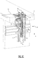
- Cylinder 6 ( figure 2A ) comprises outer cylinder 30 which comprises an inner space 31.
- Outer cylinder 30 is connected to frame 6 for movement in substantially vertical direction V relative to ground surface 3.
- piston rod 32 Arranged movably in inner space 31 of outer cylinder 30 is piston rod 32.
- rollers 34 Connected operatively to piston rod 32 are rollers 34, which are positioned on either side of piston rod 32.
- Teat cup carrier 8 is arranged on upper side 33 of outer cylinder 30.
- milking device 2 is in rest state 50.
- cover plate 18 of closure 14 wholly closes ground surface 3 so that in rest state 50 no dirt is able to find its way onto or into teat cup carrier 8 and teat cups 10.
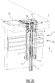
- Piston rod 32 ( figure 2C ) can then be moved upward in inner space 31 of outer cylinder 30 in the direction of ground surface 3. Because rollers 34 are in the shown embodiment operatively connected to piston rod 32, rollers 34 are also moved upward. This creates slack in milk hoses 12 so that a milker has enough length of milk hose 12 to take teat cups 10 off teat cup carrier 8 and then move them upward for placing on the teats of an animal to be milked. Alternatively or additionally, rollers 34 are operatively connected to milk hoses 12, whereby milk hoses 12 are co-displaced in the direction of ground surface 3 when piston rod 32 is moved upward. In figure 2C milking device 2 is in milking state 52. In milking state 52 the teat cup carrier can be locked by means of an electronic lock so that it is guaranteed to be located close to ground surface 3 during milking state 52.
- teat cups 10 ( figure 2D ) can be washed on underside 28 of cover plate 18.
- teat cups 10 are pressed onto flushing device 26 when cover plate 18 wholly covers the ground surface. This can for instance be realized in simple manner when the milking device is in rest state 50 (see figure 2A ).
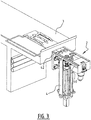
- Milking device 2 ( figure 3 ) can be removed from ground surface 3 as a whole.
- milking device 2 comprises guides 40 which co-act with guides 42 provided on ground surface 3.
- Milking device 2 can hereby be removed from ground surface 3 in simple manner and be easily maintained, cleaned, repaired or replaced.
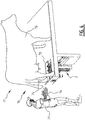
- Milking system 70 ( figure 4 ) arranged in milking parlour 71 comprises RFID antenna 72 arranged on milking device 2 and animal RFID tag 74 arranged on cow 75. Milking system 70 further comprises milker RFID tag 76 which is arranged on milker 77. RFID antenna 72 can communicate by means of a wireless RFID connection to animal RFID tag 74 and milker RFID tag 76. By means of animal RFID tag 74 RFID antenna 72 is easily able to recognize whether an animal and which animal 75 is standing above milking device 2, and whether a milker and which milker 77 is standing close to milking device 2.
- Teat cup 214 ( figure 5 ) is provided with teat cup liner 204.
- Teat cup liner 204 is provided with flexible wall part 218 which extends substantially in the interior of a teat cup 214.
- pulsation chamber 220 a varying pressure is exerted in pulsation chamber 220 as a result of the pulsation, whereby wall part 218 is periodically compressed and opened so as to thereby exert a pulsating action on a teat.
- head or buffer area or teat chamber 222 is provided on the upper side of teat cup liner 204.
- Pressure compensator 206 provides for supply of air for regulating the pressure in head or teat chamber 222 thereby.
- teat chamber 222 and/or pressure compensator 206 are not essential to the invention, and numerous embodiments are possible according to the invention without teat chamber 222 and/or pressure compensator 206.
- pulsation chamber 220 is placed under pressure, for instance a pressure of 0.2 bar, such that flexible wall part 218 of teat cup liner 204 is compressed.
- Placing pulsation chamber 220 under pressure can for instance be realized with a 3/2 valve known from the prior art.
- a vacuum can hereby be created in the milk hose without "false" air being drawn in from teat chamber 222.
- the advantage hereof is that a milker can connect two teat cups 214 to the teats of the animal to be milked at the same time in simple manner without "false” air being drawn in at the other teat cups.
- milking device 2 is in rest state 50.
- cover plate 18 wholly covers ground surface 3.
- Closure 14 is rotated about rotation axis 16 by rotation cylinder 24, whereby milking plate 20 partially closes ground surface 3.
- Teat cup carrier 8 is then moved upward in vertical direction V toward ground surface 3 by first stroke 100 ( figure 6 ) of outer cylinder 30, whereby teat cups 10 are moved through openings 22 of milking plate 20.
- the starting position of first stroke 100 of outer cylinder 30 is figure 2A
- the end position of first stroke 100 of outer cylinder 30 is figure 2B .
- piston rod 32 is moved in vertical direction V toward ground surface 3 in inner space 31 of outer cylinder 30 by means of second stroke 102. Rollers 34 are hereby moved upward, with the result that milk hoses 12 obtain slack.
- Milking device 2 is then in milking state 52.
- the starting position of second stroke 102 of piston rod 32 is figure 2B and the end position of the second stroke 102 of piston rod 32 is figure 2C .
- a milker can easily take two teat cups 10 from teat cup carrier 8 at the same time and place them on the teats of the animal to be milked.
- Light source 60 can optionally give an indication that the milking process can be started.
- Valve unit 90 can further be controlled to carry milk to the desired flow.
- valve unit 90 This choice depends for instance on the condition of the animal to be milked, the demand, and the like.
- the controlling of valve unit 90 is for instance dependent on information received by RFID antenna 72 from animal RFID tag 74 and milker RFID tag 76.
- the settings or startup of the milking process can also be controlled on the basis of RFID tag 74 and milker RFID tag 76, which are read by RFID antenna 72. After this, the milking process can start.
- teat cups 10 are placed back on teat cup carrier 8 by the milker.
- Piston rod 32 is then moved in vertical direction V away from ground surface 3 with second stroke 104.
- Rollers 34 hereby engage on milk hoses 12, whereby milk hoses 12 are tightened. Unnecessary bending and/or kinking of milk hoses 12 before milking device 2 is returned back to rest state 50 is hereby prevented.
- An advantage hereof is that wear of milking device 2 is reduced.
- Second stroke 104 is opposite to second stroke 102.
- Outer cylinder 30 is then moved in vertical direction V away from ground surface 3 by first stroke 106.
- Teat cup carrier 8 with teat cups 10 placed thereon is hereby moved to a position below ground surface 3.
- First stroke 106 is opposite to first stroke 102.
- closure 14 can be rotated about rotation axis 16 by means of rotation cylinder 24 such that cover plate 18 wholly covers ground surface 3.
- teat cups 10 can then be moved upward against flushing device 26 which is mounted on underside 28 of cover plate 18. This realizes an easy cleaning of teat cups 10. It will be apparent to the skilled person that it is also possible in the discussed embodiments to reverse the outer cylinder and piston in terms of functionality. In the context of the invention the outer cylinder and piston can also be referred to as first and second cylinder.
Landscapes
- Life Sciences & Earth Sciences (AREA)
- Environmental Sciences (AREA)
- Animal Husbandry (AREA)
- Zoology (AREA)
- Biodiversity & Conservation Biology (AREA)
- External Artificial Organs (AREA)
Applications Claiming Priority (1)
| Application Number | Priority Date | Filing Date | Title |
|---|---|---|---|
| NL2025365A NL2025365B1 (nl) | 2020-04-17 | 2020-04-17 | Melkinrichting, melksysteem en werkwijze daarvoor |
Publications (3)
| Publication Number | Publication Date |
|---|---|
| EP3895526A1 true EP3895526A1 (de) | 2021-10-20 |
| EP3895526C0 EP3895526C0 (de) | 2024-06-05 |
| EP3895526B1 EP3895526B1 (de) | 2024-06-05 |
Family
ID=70614558
Family Applications (1)
| Application Number | Title | Priority Date | Filing Date |
|---|---|---|---|
| EP21168961.7A Active EP3895526B1 (de) | 2020-04-17 | 2021-04-16 | Melkvorrichtung, melksystem und verfahren hierfür |
Country Status (3)
| Country | Link |
|---|---|
| EP (1) | EP3895526B1 (de) |
| ES (1) | ES2984839T3 (de) |
| NL (1) | NL2025365B1 (de) |
Citations (5)
| Publication number | Priority date | Publication date | Assignee | Title |
|---|---|---|---|---|
| US4010714A (en) * | 1974-03-08 | 1977-03-08 | Director, National Institute Of Animal Industry | System for managing milking-cows in stanchion stool |
| EP0332235A2 (de) * | 1985-07-01 | 1989-09-13 | C. van der Lely N.V. | Gerät zum automatischen Melken von Tieren |
| WO2000004765A1 (en) * | 1998-07-24 | 2000-02-03 | Alfa Laval Agri Ab | A device for automatically attaching a teatcup onto a teat of an animal |
| US20080210171A1 (en) * | 2006-09-29 | 2008-09-04 | Thomas Mader | Milking parlor |
| US20120272914A1 (en) * | 2011-04-28 | 2012-11-01 | Technologies Holdings Corp. | Milking box with robotic attacher and vision system |
-
2020
- 2020-04-17 NL NL2025365A patent/NL2025365B1/nl active
-
2021
- 2021-04-16 ES ES21168961T patent/ES2984839T3/es active Active
- 2021-04-16 EP EP21168961.7A patent/EP3895526B1/de active Active
Patent Citations (5)
| Publication number | Priority date | Publication date | Assignee | Title |
|---|---|---|---|---|
| US4010714A (en) * | 1974-03-08 | 1977-03-08 | Director, National Institute Of Animal Industry | System for managing milking-cows in stanchion stool |
| EP0332235A2 (de) * | 1985-07-01 | 1989-09-13 | C. van der Lely N.V. | Gerät zum automatischen Melken von Tieren |
| WO2000004765A1 (en) * | 1998-07-24 | 2000-02-03 | Alfa Laval Agri Ab | A device for automatically attaching a teatcup onto a teat of an animal |
| US20080210171A1 (en) * | 2006-09-29 | 2008-09-04 | Thomas Mader | Milking parlor |
| US20120272914A1 (en) * | 2011-04-28 | 2012-11-01 | Technologies Holdings Corp. | Milking box with robotic attacher and vision system |
Also Published As
| Publication number | Publication date |
|---|---|
| EP3895526C0 (de) | 2024-06-05 |
| EP3895526B1 (de) | 2024-06-05 |
| ES2984839T3 (es) | 2024-10-31 |
| NL2025365B1 (nl) | 2021-10-26 |
Similar Documents
| Publication | Publication Date | Title |
|---|---|---|
| US8925484B2 (en) | Retaining device for teat cups and actuator for inciting a movement of a teat cup cluster | |
| CA2866008C (en) | Space divider of a milking parlor arrangement, and milking parlor arrangement | |
| US8770146B2 (en) | Methods and apparatus for applying teat dip to a dairy animal | |
| US10349618B2 (en) | System and method of attaching a cup to a dairy animal according to a sequence | |
| US9648840B2 (en) | Milking robot with robotic arm, vision system, and vision system cleaning device | |
| EP3202255B1 (de) | Melkbox mit reinigungssystem | |
| EP1011314B1 (de) | Vorrichtung zum an- und abkoppeln von melkbechern und automatische melkeinrichtung dazu | |
| EP1230844B1 (de) | Reinigungsvorrichtung | |
| US9737041B2 (en) | System and method of attaching cups to a dairy animal | |
| US7334537B2 (en) | Method of milking an animal and device for this purpose | |
| US10143179B2 (en) | Milking box with a robotic attacher having a three-dimensional range of motion | |
| EP3895526B1 (de) | Melkvorrichtung, melksystem und verfahren hierfür | |
| EP0645079A1 (de) | Vorrichtung zum automatischen Melken von Tieren | |
| RU2257707C1 (ru) | Двухрежимный доильный аппарат | |
| RU2189737C2 (ru) | Мобильный автомат доения коров | |
| US8001930B2 (en) | System and method for milking animals | |
| KR102479798B1 (ko) | 자동 우유 착유시스템 | |
| RU2084136C1 (ru) | Доильный аппарат винникова и.к. | |
| WO2007137579A2 (en) | Automatic cleaning of milk cans | |
| JPH07274755A (ja) | 搾乳機 | |
| JP3007799B2 (ja) | 搾乳設備 | |
| US20240315196A1 (en) | Milking device and method for milking an animal | |
| RU2493696C1 (ru) | Доильный аппарат | |
| CA2314887C (en) | An animal related apparatus | |
| US20230017609A1 (en) | A preparation robot for preparing the teats of an animal, a teat preparation arrangement and a method of preparing teats |
Legal Events
| Date | Code | Title | Description |
|---|---|---|---|
| PUAI | Public reference made under article 153(3) epc to a published international application that has entered the european phase |
Free format text: ORIGINAL CODE: 0009012 |
|
| STAA | Information on the status of an ep patent application or granted ep patent |
Free format text: STATUS: THE APPLICATION HAS BEEN PUBLISHED |
|
| AK | Designated contracting states |
Kind code of ref document: A1 Designated state(s): AL AT BE BG CH CY CZ DE DK EE ES FI FR GB GR HR HU IE IS IT LI LT LU LV MC MK MT NL NO PL PT RO RS SE SI SK SM TR |
|
| B565 | Issuance of search results under rule 164(2) epc |
Effective date: 20210922 |
|
| STAA | Information on the status of an ep patent application or granted ep patent |
Free format text: STATUS: REQUEST FOR EXAMINATION WAS MADE |
|
| 17P | Request for examination filed |
Effective date: 20220420 |
|
| RBV | Designated contracting states (corrected) |
Designated state(s): AL AT BE BG CH CY CZ DE DK EE ES FI FR GB GR HR HU IE IS IT LI LT LU LV MC MK MT NL NO PL PT RO RS SE SI SK SM TR |
|
| GRAP | Despatch of communication of intention to grant a patent |
Free format text: ORIGINAL CODE: EPIDOSNIGR1 |
|
| STAA | Information on the status of an ep patent application or granted ep patent |
Free format text: STATUS: GRANT OF PATENT IS INTENDED |
|
| RAP1 | Party data changed (applicant data changed or rights of an application transferred) |
Owner name: BOUMATIC TECHNOLOGY B.V. |
|
| INTG | Intention to grant announced |
Effective date: 20231212 |
|
| GRAS | Grant fee paid |
Free format text: ORIGINAL CODE: EPIDOSNIGR3 |
|
| GRAA | (expected) grant |
Free format text: ORIGINAL CODE: 0009210 |
|
| STAA | Information on the status of an ep patent application or granted ep patent |
Free format text: STATUS: THE PATENT HAS BEEN GRANTED |
|
| AK | Designated contracting states |
Kind code of ref document: B1 Designated state(s): AL AT BE BG CH CY CZ DE DK EE ES FI FR GB GR HR HU IE IS IT LI LT LU LV MC MK MT NL NO PL PT RO RS SE SI SK SM TR |
|
| REG | Reference to a national code |
Ref country code: CH Ref legal event code: EP |
|
| REG | Reference to a national code |
Ref country code: DE Ref legal event code: R096 Ref document number: 602021013981 Country of ref document: DE |
|
| REG | Reference to a national code |
Ref country code: IE Ref legal event code: FG4D |
|
| U01 | Request for unitary effect filed |
Effective date: 20240621 |
|
| U07 | Unitary effect registered |
Designated state(s): AT BE BG DE DK EE FI FR IT LT LU LV MT NL PT SE SI Effective date: 20240708 |
|
| PG25 | Lapsed in a contracting state [announced via postgrant information from national office to epo] |
Ref country code: HR Free format text: LAPSE BECAUSE OF FAILURE TO SUBMIT A TRANSLATION OF THE DESCRIPTION OR TO PAY THE FEE WITHIN THE PRESCRIBED TIME-LIMIT Effective date: 20240605 |
|
| PG25 | Lapsed in a contracting state [announced via postgrant information from national office to epo] |
Ref country code: GR Free format text: LAPSE BECAUSE OF FAILURE TO SUBMIT A TRANSLATION OF THE DESCRIPTION OR TO PAY THE FEE WITHIN THE PRESCRIBED TIME-LIMIT Effective date: 20240906 |
|
| PG25 | Lapsed in a contracting state [announced via postgrant information from national office to epo] |
Ref country code: NO Free format text: LAPSE BECAUSE OF FAILURE TO SUBMIT A TRANSLATION OF THE DESCRIPTION OR TO PAY THE FEE WITHIN THE PRESCRIBED TIME-LIMIT Effective date: 20240905 Ref country code: HR Free format text: LAPSE BECAUSE OF FAILURE TO SUBMIT A TRANSLATION OF THE DESCRIPTION OR TO PAY THE FEE WITHIN THE PRESCRIBED TIME-LIMIT Effective date: 20240605 Ref country code: GR Free format text: LAPSE BECAUSE OF FAILURE TO SUBMIT A TRANSLATION OF THE DESCRIPTION OR TO PAY THE FEE WITHIN THE PRESCRIBED TIME-LIMIT Effective date: 20240906 Ref country code: RS Free format text: LAPSE BECAUSE OF FAILURE TO SUBMIT A TRANSLATION OF THE DESCRIPTION OR TO PAY THE FEE WITHIN THE PRESCRIBED TIME-LIMIT Effective date: 20240905 |
|
| REG | Reference to a national code |
Ref country code: ES Ref legal event code: FG2A Ref document number: 2984839 Country of ref document: ES Kind code of ref document: T3 Effective date: 20241031 |
|
| PG25 | Lapsed in a contracting state [announced via postgrant information from national office to epo] |
Ref country code: PL Free format text: LAPSE BECAUSE OF FAILURE TO SUBMIT A TRANSLATION OF THE DESCRIPTION OR TO PAY THE FEE WITHIN THE PRESCRIBED TIME-LIMIT Effective date: 20240605 |
|
| PG25 | Lapsed in a contracting state [announced via postgrant information from national office to epo] |
Ref country code: IS Free format text: LAPSE BECAUSE OF FAILURE TO SUBMIT A TRANSLATION OF THE DESCRIPTION OR TO PAY THE FEE WITHIN THE PRESCRIBED TIME-LIMIT Effective date: 20241005 |
|
| PG25 | Lapsed in a contracting state [announced via postgrant information from national office to epo] |
Ref country code: CZ Free format text: LAPSE BECAUSE OF FAILURE TO SUBMIT A TRANSLATION OF THE DESCRIPTION OR TO PAY THE FEE WITHIN THE PRESCRIBED TIME-LIMIT Effective date: 20240605 |
|
| PG25 | Lapsed in a contracting state [announced via postgrant information from national office to epo] |
Ref country code: RO Free format text: LAPSE BECAUSE OF FAILURE TO SUBMIT A TRANSLATION OF THE DESCRIPTION OR TO PAY THE FEE WITHIN THE PRESCRIBED TIME-LIMIT Effective date: 20240605 Ref country code: SK Free format text: LAPSE BECAUSE OF FAILURE TO SUBMIT A TRANSLATION OF THE DESCRIPTION OR TO PAY THE FEE WITHIN THE PRESCRIBED TIME-LIMIT Effective date: 20240605 |
|
| PG25 | Lapsed in a contracting state [announced via postgrant information from national office to epo] |
Ref country code: SM Free format text: LAPSE BECAUSE OF FAILURE TO SUBMIT A TRANSLATION OF THE DESCRIPTION OR TO PAY THE FEE WITHIN THE PRESCRIBED TIME-LIMIT Effective date: 20240605 |
|
| PG25 | Lapsed in a contracting state [announced via postgrant information from national office to epo] |
Ref country code: SM Free format text: LAPSE BECAUSE OF FAILURE TO SUBMIT A TRANSLATION OF THE DESCRIPTION OR TO PAY THE FEE WITHIN THE PRESCRIBED TIME-LIMIT Effective date: 20240605 Ref country code: SK Free format text: LAPSE BECAUSE OF FAILURE TO SUBMIT A TRANSLATION OF THE DESCRIPTION OR TO PAY THE FEE WITHIN THE PRESCRIBED TIME-LIMIT Effective date: 20240605 Ref country code: RO Free format text: LAPSE BECAUSE OF FAILURE TO SUBMIT A TRANSLATION OF THE DESCRIPTION OR TO PAY THE FEE WITHIN THE PRESCRIBED TIME-LIMIT Effective date: 20240605 Ref country code: PL Free format text: LAPSE BECAUSE OF FAILURE TO SUBMIT A TRANSLATION OF THE DESCRIPTION OR TO PAY THE FEE WITHIN THE PRESCRIBED TIME-LIMIT Effective date: 20240605 Ref country code: IS Free format text: LAPSE BECAUSE OF FAILURE TO SUBMIT A TRANSLATION OF THE DESCRIPTION OR TO PAY THE FEE WITHIN THE PRESCRIBED TIME-LIMIT Effective date: 20241005 Ref country code: CZ Free format text: LAPSE BECAUSE OF FAILURE TO SUBMIT A TRANSLATION OF THE DESCRIPTION OR TO PAY THE FEE WITHIN THE PRESCRIBED TIME-LIMIT Effective date: 20240605 |
|
| PLBE | No opposition filed within time limit |
Free format text: ORIGINAL CODE: 0009261 |
|
| STAA | Information on the status of an ep patent application or granted ep patent |
Free format text: STATUS: NO OPPOSITION FILED WITHIN TIME LIMIT |
|
| 26N | No opposition filed |
Effective date: 20250306 |
|
| U20 | Renewal fee for the european patent with unitary effect paid |
Year of fee payment: 5 Effective date: 20250428 |
|
| PGFP | Annual fee paid to national office [announced via postgrant information from national office to epo] |
Ref country code: GB Payment date: 20250428 Year of fee payment: 5 Ref country code: ES Payment date: 20250505 Year of fee payment: 5 |
|
| REG | Reference to a national code |
Ref country code: CH Ref legal event code: H13 Free format text: ST27 STATUS EVENT CODE: U-0-0-H10-H13 (AS PROVIDED BY THE NATIONAL OFFICE) Effective date: 20251125 |
|
| PG25 | Lapsed in a contracting state [announced via postgrant information from national office to epo] |
Ref country code: MC Free format text: LAPSE BECAUSE OF FAILURE TO SUBMIT A TRANSLATION OF THE DESCRIPTION OR TO PAY THE FEE WITHIN THE PRESCRIBED TIME-LIMIT Effective date: 20240605 |
|
| PG25 | Lapsed in a contracting state [announced via postgrant information from national office to epo] |
Ref country code: CH Free format text: LAPSE BECAUSE OF NON-PAYMENT OF DUE FEES Effective date: 20250430 |
|
| PG25 | Lapsed in a contracting state [announced via postgrant information from national office to epo] |
Ref country code: IE Free format text: LAPSE BECAUSE OF NON-PAYMENT OF DUE FEES Effective date: 20250416 |