EP3896018A1 - Procédé et dispositif d'alimentation à position exacte des feuilles de tôle destinés à un processus de traitement ou une unité de traitement - Google Patents
Procédé et dispositif d'alimentation à position exacte des feuilles de tôle destinés à un processus de traitement ou une unité de traitement Download PDFInfo
- Publication number
- EP3896018A1 EP3896018A1 EP21161483.9A EP21161483A EP3896018A1 EP 3896018 A1 EP3896018 A1 EP 3896018A1 EP 21161483 A EP21161483 A EP 21161483A EP 3896018 A1 EP3896018 A1 EP 3896018A1
- Authority
- EP
- European Patent Office
- Prior art keywords
- transport
- transport device
- sheet
- metal
- metal sheet
- Prior art date
- Legal status (The legal status is an assumption and is not a legal conclusion. Google has not performed a legal analysis and makes no representation as to the accuracy of the status listed.)
- Granted
Links
Images



Classifications
-
- B—PERFORMING OPERATIONS; TRANSPORTING
- B65—CONVEYING; PACKING; STORING; HANDLING THIN OR FILAMENTARY MATERIAL
- B65H—HANDLING THIN OR FILAMENTARY MATERIAL, e.g. SHEETS, WEBS, CABLES
- B65H9/00—Registering, e.g. orientating, articles; Devices therefor
- B65H9/10—Pusher and like movable registers; Pusher or gripper devices which move articles into registered position
- B65H9/103—Pusher and like movable registers; Pusher or gripper devices which move articles into registered position acting by friction or suction on the article for pushing or pulling it into registered position, e.g. against a stop
- B65H9/105—Pusher and like movable registers; Pusher or gripper devices which move articles into registered position acting by friction or suction on the article for pushing or pulling it into registered position, e.g. against a stop using suction means
-
- B—PERFORMING OPERATIONS; TRANSPORTING
- B65—CONVEYING; PACKING; STORING; HANDLING THIN OR FILAMENTARY MATERIAL
- B65H—HANDLING THIN OR FILAMENTARY MATERIAL, e.g. SHEETS, WEBS, CABLES
- B65H11/00—Feed tables
- B65H11/002—Feed tables incorporating transport belts
- B65H11/005—Suction belts
-
- B—PERFORMING OPERATIONS; TRANSPORTING
- B65—CONVEYING; PACKING; STORING; HANDLING THIN OR FILAMENTARY MATERIAL
- B65H—HANDLING THIN OR FILAMENTARY MATERIAL, e.g. SHEETS, WEBS, CABLES
- B65H7/00—Controlling article feeding, separating, pile-advancing, or associated apparatus, to take account of incorrect feeding, absence of articles, or presence of faulty articles
- B65H7/02—Controlling article feeding, separating, pile-advancing, or associated apparatus, to take account of incorrect feeding, absence of articles, or presence of faulty articles by feelers or detectors
- B65H7/06—Controlling article feeding, separating, pile-advancing, or associated apparatus, to take account of incorrect feeding, absence of articles, or presence of faulty articles by feelers or detectors responsive to presence of faulty articles or incorrect separation or feed
- B65H7/10—Controlling article feeding, separating, pile-advancing, or associated apparatus, to take account of incorrect feeding, absence of articles, or presence of faulty articles by feelers or detectors responsive to presence of faulty articles or incorrect separation or feed responsive to incorrect side register
-
- B—PERFORMING OPERATIONS; TRANSPORTING
- B65—CONVEYING; PACKING; STORING; HANDLING THIN OR FILAMENTARY MATERIAL
- B65H—HANDLING THIN OR FILAMENTARY MATERIAL, e.g. SHEETS, WEBS, CABLES
- B65H7/00—Controlling article feeding, separating, pile-advancing, or associated apparatus, to take account of incorrect feeding, absence of articles, or presence of faulty articles
- B65H7/02—Controlling article feeding, separating, pile-advancing, or associated apparatus, to take account of incorrect feeding, absence of articles, or presence of faulty articles by feelers or detectors
- B65H7/14—Controlling article feeding, separating, pile-advancing, or associated apparatus, to take account of incorrect feeding, absence of articles, or presence of faulty articles by feelers or detectors by photoelectric feelers or detectors
-
- B—PERFORMING OPERATIONS; TRANSPORTING
- B65—CONVEYING; PACKING; STORING; HANDLING THIN OR FILAMENTARY MATERIAL
- B65H—HANDLING THIN OR FILAMENTARY MATERIAL, e.g. SHEETS, WEBS, CABLES
- B65H2301/00—Handling processes for sheets or webs
- B65H2301/30—Orientation, displacement, position of the handled material
- B65H2301/33—Modifying, selecting, changing orientation
- B65H2301/331—Skewing, correcting skew, i.e. changing slightly orientation of material
-
- B—PERFORMING OPERATIONS; TRANSPORTING
- B65—CONVEYING; PACKING; STORING; HANDLING THIN OR FILAMENTARY MATERIAL
- B65H—HANDLING THIN OR FILAMENTARY MATERIAL, e.g. SHEETS, WEBS, CABLES
- B65H2301/00—Handling processes for sheets or webs
- B65H2301/40—Type of handling process
- B65H2301/44—Moving, forwarding, guiding material
- B65H2301/447—Moving, forwarding, guiding material transferring material between transport devices
- B65H2301/4473—Belts, endless moving elements on which the material is in surface contact
- B65H2301/44735—Belts, endless moving elements on which the material is in surface contact suction belt
-
- B—PERFORMING OPERATIONS; TRANSPORTING
- B65—CONVEYING; PACKING; STORING; HANDLING THIN OR FILAMENTARY MATERIAL
- B65H—HANDLING THIN OR FILAMENTARY MATERIAL, e.g. SHEETS, WEBS, CABLES
- B65H2404/00—Parts for transporting or guiding the handled material
- B65H2404/20—Belts
- B65H2404/26—Particular arrangement of belt, or belts
- B65H2404/264—Arrangement of side-by-side belts
- B65H2404/2641—Arrangement of side-by-side belts on movable frame
-
- B—PERFORMING OPERATIONS; TRANSPORTING
- B65—CONVEYING; PACKING; STORING; HANDLING THIN OR FILAMENTARY MATERIAL
- B65H—HANDLING THIN OR FILAMENTARY MATERIAL, e.g. SHEETS, WEBS, CABLES
- B65H2404/00—Parts for transporting or guiding the handled material
- B65H2404/20—Belts
- B65H2404/26—Particular arrangement of belt, or belts
- B65H2404/269—Particular arrangement of belt, or belts other arrangements
- B65H2404/2691—Arrangement of successive belts forming a transport path
-
- B—PERFORMING OPERATIONS; TRANSPORTING
- B65—CONVEYING; PACKING; STORING; HANDLING THIN OR FILAMENTARY MATERIAL
- B65H—HANDLING THIN OR FILAMENTARY MATERIAL, e.g. SHEETS, WEBS, CABLES
- B65H2406/00—Means using fluid
- B65H2406/10—Means using fluid made only for exhausting gaseous medium
- B65H2406/11—Means using fluid made only for exhausting gaseous medium producing fluidised bed
- B65H2406/113—Details of the part distributing the air cushion
- B65H2406/1132—Multiple nozzles arrangement
-
- B—PERFORMING OPERATIONS; TRANSPORTING
- B65—CONVEYING; PACKING; STORING; HANDLING THIN OR FILAMENTARY MATERIAL
- B65H—HANDLING THIN OR FILAMENTARY MATERIAL, e.g. SHEETS, WEBS, CABLES
- B65H2406/00—Means using fluid
- B65H2406/30—Suction means
- B65H2406/32—Suction belts
- B65H2406/321—Suction belts integral in feed table
-
- B—PERFORMING OPERATIONS; TRANSPORTING
- B65—CONVEYING; PACKING; STORING; HANDLING THIN OR FILAMENTARY MATERIAL
- B65H—HANDLING THIN OR FILAMENTARY MATERIAL, e.g. SHEETS, WEBS, CABLES
- B65H2406/00—Means using fluid
- B65H2406/30—Suction means
- B65H2406/32—Suction belts
- B65H2406/322—Suction distributing means
- B65H2406/3221—Suction distributing means for variable distribution in the direction of transport
-
- B—PERFORMING OPERATIONS; TRANSPORTING
- B65—CONVEYING; PACKING; STORING; HANDLING THIN OR FILAMENTARY MATERIAL
- B65H—HANDLING THIN OR FILAMENTARY MATERIAL, e.g. SHEETS, WEBS, CABLES
- B65H2406/00—Means using fluid
- B65H2406/30—Suction means
- B65H2406/32—Suction belts
- B65H2406/322—Suction distributing means
- B65H2406/3222—Suction distributing means switchable suction elements
-
- B—PERFORMING OPERATIONS; TRANSPORTING
- B65—CONVEYING; PACKING; STORING; HANDLING THIN OR FILAMENTARY MATERIAL
- B65H—HANDLING THIN OR FILAMENTARY MATERIAL, e.g. SHEETS, WEBS, CABLES
- B65H2406/00—Means using fluid
- B65H2406/30—Suction means
- B65H2406/36—Means for producing, distributing or controlling suction
- B65H2406/365—Means for producing, distributing or controlling suction selectively blowing or sucking
-
- B—PERFORMING OPERATIONS; TRANSPORTING
- B65—CONVEYING; PACKING; STORING; HANDLING THIN OR FILAMENTARY MATERIAL
- B65H—HANDLING THIN OR FILAMENTARY MATERIAL, e.g. SHEETS, WEBS, CABLES
- B65H2511/00—Dimensions; Position; Numbers; Identification; Occurrences
- B65H2511/20—Location in space
- B65H2511/24—Irregularities, e.g. in orientation or skewness
-
- B—PERFORMING OPERATIONS; TRANSPORTING
- B65—CONVEYING; PACKING; STORING; HANDLING THIN OR FILAMENTARY MATERIAL
- B65H—HANDLING THIN OR FILAMENTARY MATERIAL, e.g. SHEETS, WEBS, CABLES
- B65H2513/00—Dynamic entities; Timing aspects
- B65H2513/10—Speed
-
- B—PERFORMING OPERATIONS; TRANSPORTING
- B65—CONVEYING; PACKING; STORING; HANDLING THIN OR FILAMENTARY MATERIAL
- B65H—HANDLING THIN OR FILAMENTARY MATERIAL, e.g. SHEETS, WEBS, CABLES
- B65H2553/00—Sensing or detecting means
- B65H2553/40—Sensing or detecting means using optical, e.g. photographic, elements
- B65H2553/41—Photoelectric detectors
- B65H2553/412—Photoelectric detectors in barrier arrangements, i.e. emitter facing a receptor element
-
- B—PERFORMING OPERATIONS; TRANSPORTING
- B65—CONVEYING; PACKING; STORING; HANDLING THIN OR FILAMENTARY MATERIAL
- B65H—HANDLING THIN OR FILAMENTARY MATERIAL, e.g. SHEETS, WEBS, CABLES
- B65H2553/00—Sensing or detecting means
- B65H2553/40—Sensing or detecting means using optical, e.g. photographic, elements
- B65H2553/41—Photoelectric detectors
- B65H2553/416—Array arrangement, i.e. row of emitters or detectors
-
- B—PERFORMING OPERATIONS; TRANSPORTING
- B65—CONVEYING; PACKING; STORING; HANDLING THIN OR FILAMENTARY MATERIAL
- B65H—HANDLING THIN OR FILAMENTARY MATERIAL, e.g. SHEETS, WEBS, CABLES
- B65H2701/00—Handled material; Storage means
- B65H2701/10—Handled articles or webs
- B65H2701/13—Parts concerned of the handled material
- B65H2701/131—Edges
- B65H2701/1311—Edges leading edge
-
- B—PERFORMING OPERATIONS; TRANSPORTING
- B65—CONVEYING; PACKING; STORING; HANDLING THIN OR FILAMENTARY MATERIAL
- B65H—HANDLING THIN OR FILAMENTARY MATERIAL, e.g. SHEETS, WEBS, CABLES
- B65H2701/00—Handled material; Storage means
- B65H2701/10—Handled articles or webs
- B65H2701/13—Parts concerned of the handled material
- B65H2701/131—Edges
- B65H2701/1315—Edges side edges, i.e. regarded in context of transport
-
- B—PERFORMING OPERATIONS; TRANSPORTING
- B65—CONVEYING; PACKING; STORING; HANDLING THIN OR FILAMENTARY MATERIAL
- B65H—HANDLING THIN OR FILAMENTARY MATERIAL, e.g. SHEETS, WEBS, CABLES
- B65H2701/00—Handled material; Storage means
- B65H2701/10—Handled articles or webs
- B65H2701/17—Nature of material
- B65H2701/173—Metal
-
- B—PERFORMING OPERATIONS; TRANSPORTING
- B65—CONVEYING; PACKING; STORING; HANDLING THIN OR FILAMENTARY MATERIAL
- B65H—HANDLING THIN OR FILAMENTARY MATERIAL, e.g. SHEETS, WEBS, CABLES
- B65H2801/00—Application field
- B65H2801/03—Image reproduction devices
- B65H2801/21—Industrial-size printers, e.g. rotary printing press
-
- B—PERFORMING OPERATIONS; TRANSPORTING
- B65—CONVEYING; PACKING; STORING; HANDLING THIN OR FILAMENTARY MATERIAL
- B65H—HANDLING THIN OR FILAMENTARY MATERIAL, e.g. SHEETS, WEBS, CABLES
- B65H2801/00—Application field
- B65H2801/42—Die-cutting
Definitions
- the invention relates to a method and a device for precisely positioned feeding of sheet metal to a printing or painting unit of a sheet metal coating machine.
- the metal sheets which are transported lying one behind the other, hit the positioning marks or stops during their transport, so that the metal sheets are thereby forcibly brought into the desired or precise position.
- a tilt correction can be provided for this purpose.
- the front edge of the metal sheet is aligned essentially at right angles to the direction of transport.
- a lateral alignment of the sheet metal is provided so that it can be fed to the machining process in the middle.
- an optimal longitudinal alignment of the sheet metal with respect to the transport path is necessary so that it is fed to the machining process or the machining unit at the right time.
- the DE 198 14 141 C2 describes a method for the precisely positioned feeding of sheet-like goods to a processing process, the goods being transported in a lying position in a row and being aligned during transport. The necessary alignment movements take place without mechanical alignment action on one or more peripheral edges of the goods.
- the required skew correction of the front edge, the side alignment and the longitudinal alignment are carried out by two transport devices arranged one after the other, the first transport device only realizing the skew correction and the second transport device realizing the side and longitudinal alignment.
- the inclination correction by the first transport device causes an undesired displacement of the goods transversely to the transport direction, which must be corrected with the second transport device.
- the DE 692 07 737 T2 discloses an apparatus for handling and aligning bundles of flat objects.
- the device comprises two vertical to each other displaceable conveyors, one of which consists of a table with driven balls and the other of which comprises a series of separate driven rollers.
- the control of the conveying organs takes place according to the desired lateral displacement and the desired orientation, which is to be imparted to the bundle of flat objects in each case.
- the DE 10 2017 012 279 B3 describes a sheet processing machine with a sheet separator, a sheet guide system, an acceleration device, a first alignment device with a rotating stop and a second alignment device.
- a sensor that detects the position of the stop is provided for the purpose of aligning the sheets.
- the invention is based on the object of creating a method and a device for precisely positioned feeding of sheet metal to a printing or painting unit of a sheet metal coating machine, which enables high feeding accuracy even at high processing speeds.
- the advantages that can be achieved with the invention are, in particular, that the alignment of sheet-like metal sheets in motion takes place without mechanical stops, the correction of the inclined position of a sheet-like sheet metal sheet having no undesirable effects on its lateral position.
- the alignment of the side position takes place on a second transport device, which is located downstream of the first transport device.
- the second transport device only needs to correct the lateral position to the extent that was already required before the inclination correction by the first transport device.
- the solution found also has the advantage that the transport device transport device is variable in width and is suitable for the transport of flat goods of different widths without structural adaptation.
- the width of a sheet metal sheet extends transversely to its respective transport direction.
- the transport device preferably transports the sheet-like metal sheets in each case largely floating on an air cushion.
- the sheet-like metal sheets to be transported rest only on suction belts, the suction belts in question being arranged in particular in pairs parallel to one another. Otherwise, the sheet-like metal sheets have no direct physical contact, e.g. B. to fixed air boxes in their transport plane. Due to this configuration, a largely friction-free and / or slip-free transport of the sheet-like metal sheets is possible.
- the first and the second transport device can each have circulating transport means and vacuum areas which are assigned to them and which can be switched independently of one another.
- the vacuum areas can be deactivated or activated one after the other, which in particular ensures safe guidance of the respective causes flat sheet metal in connection with the possibility of aligning the same, wherein the transport device has a small extent in the transport direction.
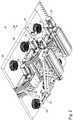
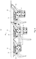
- Fig. 1 shows a transport device 01 for precisely positioned feeding of sheet-like metal sheets to a processing unit, not shown, which can be a painting machine or a printing machine or a punching machine.
- the processing unit can be designed in particular for processing sheet-like metal sheets.
- the processing unit is located downstream of the transport device 01 in the transport direction 06.
- the transport device 01 comprises a first transport device 10 and a second transport device 20 downstream of the first transport device 10 in the transport direction 06.
- the transport device 01 can be preceded by a separating device, not shown here, also referred to as a feeder.
- the transport device 01 can also comprise a further transport device 30, which is arranged upstream of the first transport device 10 in the transport direction 06.
- the first transport device 10 and / or the second transport device 20 and / or the further transport device 30 there are preferably blown air boxes 17; 25; 17 arranged, the air outlet openings 18; 26, preferably venturi nozzles 18; 26, for producing a blown air cushion that supports the sheet-like metal sheets in a contactless manner.
- the blow boxes 17; 25 are outside of the transport devices 10; 30; 20 trained.
- the blown air for generating the blown air cushion is preferably generated by fans 34, which the blown air boxes 17; 25 are assigned on their subpages.
- the further transport device 30, the first transport device 10 and the second transport device 20 are connected one behind the other, so that a transfer of a respective sheet-like metal sheet from a transport device 30; 10; 20 to the next is easily possible.
- the first and the second transport device 10; 20 and preferably also the further transport device 30 have circulating transport means 11; 12; 21; 22; 31; 32, which are preferably used as a suction belt 11; 12; 21; 22; 31; 32 are formed.
- the suction belt 11; 12; 21; 22; 31; 32 are preferably toothed belts and have two guide grooves in the toothing. In one, preferably eccentric, guide groove, a guide ring is guided on the toothed pulleys without play, in the other, preferably central guide groove, a suction rail runs with play in the upper area, through which the vacuum is applied.
- the suction belts have 11; 12; 21; 22; 31; 32 vacuum holes.
- the back of the belt is equipped with suction pockets to enlarge the suction area.
- the transport devices 10; 20; 30 each have two parallel, mutually revolving suction belts 11; 12; 21; 22; 31; 32 on. Further preferred are individual or each suction belt 11; 12; 21; 22; 31; 32 each associated with two or three vacuum areas 16 that can be switched independently of one another.
- the vacuum areas 16 can be designed as chambers, each of the chambers being assigned a switchable valve with which the respective chamber can be alternately connected to a negative pressure source or separated from the negative pressure source as required.
- the vacuum is preferably switched via 2/3-way valves.
- the vacuum areas 16 of a respective transport device 10; 20; 30 preferably adjoin one another when viewed in the transport direction 06.
- the last sheet-like sheet metal sheet is the same transport device 30; 10; 20 can still overlap, that is, if several sheet-like sheet metal plates in the area of a respective transport device 30; 10; 20, the vacuum must be in several areas within a transport device 30; 10; 20 can be controlled separately.
- a slight overpressure can be applied to the system, in particular the vacuum areas 16. Then the valve switches between vacuum and slight overpressure.
- first transport device 10 and the second transport device 20 and a further transport device 30 can each have two suction belts 11; 12; 21; 22; 31; 32 include and the track width of the suction belt 11; 12 of the first transport device 10 be larger than the track width of the suction belt 21; 22; 31; 32 of the second transport device 20 and / or of the further transport device 30.
- the different gauges of the suction belt 11; 12; 21; 22; 31; 32 of the transport devices 10; 20; 30 overlap when viewed in the transport direction 06.
- the overlap is preferably in the range of 10 percent of the extent of the respective suction belts 11; 12; 21; 22; 31; 32 in transport direction 06.
- the transport means 11; 12; 21; 22; 31; 32, in particular the suction belt 11; 12; 21; 22; 31; 32 are paired by means of transport drives 19; 27; 33 driven in rotation.
- Each transport device 10; 20; 30 one of the other transport means drives 19; 27, 33 independent transport means drive 19; 27; 33 on.
- the suction belt 11; 12; 21; 22; 31; 32 of a pair of belts of a transport device 10; 20; 30 can also be carried out via a common drive shaft by means of a transport means drive 19; 27; 33 are driven.
- the suction belts 21; 22; 31; 32 of the second and the further transport device 20; 30 by the respective transport means drives 27; 33 can be driven for transporting sheet-like metal sheets in the transport direction 06 at a variable speed.
- the second transport device 20 has acceleratable and / or decelerable transport means 21; 22 in the form of suction belts 21; 22 on. That is, the suction belts 21; 22 can be driven at a speed that is equal to, greater than or less than a transport speed of the processing unit.
- the first transport device 10 is designed to implement a tilt correction.
- the first transport device 10 is perpendicular to the Axis running on the transport plane can be rotated and is mounted so that it can be moved transversely to the transport direction 06 with the axis being displaced.
- the rotatable mounting of the first transport device 10 can be implemented by forming a bearing point, for example a turntable, with a rotational degree of freedom.
- the rotatable mounting is preferably formed centrally in relation to the first transport device 10.
- the first transport device 10 also has a drive 15 with which the first transport device 10 can be rotated about an axis running through the bearing point.
- the axis is preferably perpendicular to the transport plane.
- the drive 15 can be formed by an electromechanical cylinder 15 which acts on the first transport device 10 or its parts via a lever.
- the first transport device 10 is also mounted displaceably transversely to the transport direction 06.
- the first transport device 10 preferably has a linear guide 14.
- the first transport device 10 also comprises a drive 13 with which the displacement of the first transport device 10 transversely to the transport direction 06 can be effected via the linear guide 14.
- the drives 13; 15 can be controlled independently of one another.
- the second transport device 20 is designed to carry out a lateral position correction and for this purpose is preferably mounted such that it can only be displaced transversely to the transport direction 06.
- the structural design of the storage means and drive means for realizing the displaceability transversely to the transport direction 06 is in the first and the second transport device 10; 20 preferably identical.
- the second transport device 20 has a linear guide 24 and a drive 23 with which the second transport device 20 can be displaced on the linear guide 24 transversely to the transport direction 06.
- the further transport device 30 is mounted rigidly in the frame.
- the drives 13; 23 for transverse displacement can be used as servomotors 13; 23 be formed.
- the transport devices 10; 20; 30 each as units with respective transport means drives 19; 27; 33 understood.
- the transport devices 10; 20; 30 also always the associated transport means drive 19; 27 relocatable.
- all transport devices 10; 20; 30 mounted on a common frame.
- the frame is firmly connected to the processing unit, for example a painting machine.
- first sensors 41 for detecting the inclined position of a respective sheet-like metal sheet are arranged in the transport direction 06.
- first sensors 41 can be designed as two laser light barriers or reflective laser light barriers arranged at a distance from one another transversely to the transport direction 06.
- the two first sensors 41 are preferably designed to sense very quickly and are arranged in the transport direction 06 at the same height and transversely to the transport direction 06 at a defined distance.
- the distance is preferably 620 mm.
- At least one second sensor 42 can be arranged for detecting the lateral position of a respective sheet-like metal sheet.
- Two second sensors 42 are preferably formed and each assigned to one of the two side areas of the transport path. With the arrangement of two second sensors 42, one of the two side edges of the respective sheet-like metal sheet can optionally be sensed.
- the or all of the second sensors 42 can be designed as sensors 42 extending transversely to the transport direction 06 or as sensors 42 which can be displaced transversely to the transport direction 06.
- the use of line sensors or laser line sensors is advantageous.
- At least one third sensor 43 can be arranged to detect the longitudinal position of a respective sheet-like metal sheet.
- the at least one third sensor 43 is preferably designed as a laser light barrier.
- the transport device 01 can be used to carry out a method which is described below. The procedure is not based on the use of the described transport device 01 limited.
- alignment of the edge or alignment of the position are understood to be synonymous with the correction of the edge position or correction of the position.
- the sheet-like sheet metal sheets are transported in a lying position one behind the other and aligned during transport.
- the inclined position of the respective sheet-like metal sheet is sensed and a first transport device 10 is rotated around an axis perpendicular to the transport plane and displaced transversely to the transport direction 06, depending on the sensed inclination, during the transport of the sheet-like metal sheet held by the first transport device 10.
- the first transport device 10 is preferably displaced by a distance transverse to the transport direction 06, which corresponds to the displacement of the respective flat metal sheet transversely to the transport direction 06 resulting from the rotation of the first transport device 10 during the transport of a respective sheet metal sheet.
- the shift corrects a lateral position error which results exclusively from the rotation and the superimposed further transport of a respective sheet-like metal sheet, for example by the suction belts 11, 12 during the rotation.
- the first transport device 10 conveys the respective sheet-like metal sheet somewhat obliquely, depending on the case, which is corrected by moving the first transport unit 10 transversely to the transport direction 06.
- the speed of the transverse movement is dependent on the angle of rotation.
- the resulting conveying direction of the respective sheet-like metal sheet is perpendicular to the machining gap, in particular the lacquer gap, of a machining unit.
- the displacement of the first transport unit 10 transversely to the transport direction 06 is preferably carried out as a function of the rotary deflection of the transport unit 10.
- the speed of the transverse movement depends linearly on the angle of the rotary movement.
- the lateral position of the respective sheet metal sheet is sensed and a second transport device 20 is displaced transversely to the transport direction 06 during the transport of the sheet metal sheet held by the second transport device 20.
- the lateral position correction can take place before or after the tilt correction, so that the second transport unit 20 could also be arranged in front of the first transport unit 10.
- the circulating transport means 21; 22, depending on the sensed longitudinal position of a respective sheet-like metal sheet are temporarily driven at a speed that is increased or decreased compared to the transport speed of a processing unit downstream of the second transport device 20.
- the correction of the longitudinal position of a respective sheet-like metal sheet can also be carried out with the further transport device 30.
- the transfer to the machining process must take place at a transport speed of the machining process or the machine tool.
- the sheet-like metal sheets can preferably be placed on the further and / or the second transport device 30; 20 are braked. This can be done in superposition to the longitudinal correction.
- This state is also referred to as driving the feeder with a different format than the processing unit.
- the lateral position and the longitudinal position of a respective sheet-like metal sheet are preferably corrected simultaneously by moving the second transport device 20 and changing the transport speed.
- the sheet-like metal sheets are moved by the first transport device 10 and / or the second transport device 20 or each transport device 10; 20; 30 held by vacuum.
- first transport device 10 and / or the second transport device 20 and / or each transport device 10; 20; 30 each having vacuum areas 16 adjoining one another in the transport direction 06, their vacuum is deactivated or activated in areas one after the other during the transfer and / or when a respective sheet-like metal sheet is taken over.
- the longitudinal position of the respective sheet-like metal sheet is preferably sensed during the transport of the respective sheet-like sheet metal sheet held by the second transport device 20, whereby under sensing very generally the detection with a sensor 41; 42; 43 is understood.
- the third sensor 43 provided for sensing the longitudinal position of the respective sheet-like metal sheet is preferably located in the center and measures the position of the front edge by determining the longitudinal difference, that is, the deviation from the system angle.
- the lateral position of the respective sheet-like metal sheet is preferably detected during the transport of the respective sheet-like sheet metal held by the second transport device 20 and the second transport device 20 is shifted transversely to the transport direction 06 as a function of the sensed side position.
- lateral position and the longitudinal position are sensed at the same time.
- the inclined position of the respective sheet metal sheet is sensed in particular during the transport of the sheet metal sheet held by the first transport device 10 or during the transport of the sheet metal sheet held by a further transport device 30 upstream of the first transport device 10.
- the sheet-like metal sheet is sucked in by means of a vacuum and held on a first transport path along the first transport device 10. In the area in front of the first transport path or in the area of the first transport path, an inclined position of the sheet-like metal sheet is sensed.
- the second transport path is transferred along the second transport device 20 and the vacuum is reduced in the area of the first transport path and a vacuum is built up in the area of the second transport path to hold the sheet-like metal sheet.
- the lateral position and the longitudinal position of the sheet-like metal sheet are then determined.
- the lateral movement is carried out in the area of the second transport path and / or the transport speed is temporarily changed in the area of the second transport path. This is followed by the transfer to the machining process with a transport speed of the machining process.
Landscapes
- Engineering & Computer Science (AREA)
- Mechanical Engineering (AREA)
- Registering Or Overturning Sheets (AREA)
- Delivering By Means Of Belts And Rollers (AREA)
Applications Claiming Priority (1)
| Application Number | Priority Date | Filing Date | Title |
|---|---|---|---|
| DE102020110509.6A DE102020110509B4 (de) | 2020-04-17 | 2020-04-17 | Verfahren und Vorrichtung zum positionsgenauen Zuführen von Blechtafeln zu einem Druck- oder Lackierwerk einer Blech-Beschichtungsmaschine |
Publications (2)
| Publication Number | Publication Date |
|---|---|
| EP3896018A1 true EP3896018A1 (fr) | 2021-10-20 |
| EP3896018B1 EP3896018B1 (fr) | 2022-07-13 |
Family
ID=74867461
Family Applications (1)
| Application Number | Title | Priority Date | Filing Date |
|---|---|---|---|
| EP21161483.9A Active EP3896018B1 (fr) | 2020-04-17 | 2021-03-09 | Procédé et dispositif d'alimentation à position exacte des feuilles de tôle destinés à un processus de traitement ou une unité de traitement |
Country Status (3)
| Country | Link |
|---|---|
| EP (1) | EP3896018B1 (fr) |
| DE (1) | DE102020110509B4 (fr) |
| ES (1) | ES2926457T3 (fr) |
Cited By (3)
| Publication number | Priority date | Publication date | Assignee | Title |
|---|---|---|---|---|
| EP4180373A1 (fr) * | 2021-11-11 | 2023-05-17 | Koenig & Bauer AG | Ligne de production permettant d'usiner des panneaux en tôle |
| EP4180374A1 (fr) * | 2021-11-11 | 2023-05-17 | Koenig & Bauer AG | Ligne de production permettant d'usiner des panneaux en tôle |
| WO2024231139A1 (fr) * | 2023-05-10 | 2024-11-14 | Mb Automation Gmbh & Co. Kg | Dispositif et procédé d'alimentation ou d'évacuation de matériau en couches |
Citations (6)
| Publication number | Priority date | Publication date | Assignee | Title |
|---|---|---|---|---|
| DE69207737T2 (de) | 1991-12-13 | 1996-05-30 | Bobst Sa | Einrichtung zum Handhaben und Ausrichten von gebündelten flachen Gegenständen |
| DE19814141A1 (de) * | 1998-03-30 | 1999-10-14 | Ltg Holding Gmbh | Verfahren und Vorrichtung zum positionsgenauen Zuführen von flächenförmigen Gütern zu einem Bearbeitungsprozeß |
| US5984301A (en) * | 1997-02-19 | 1999-11-16 | Carruthers Equipment Co. | Position adjustment conveyor |
| DE102007031115A1 (de) | 2007-06-28 | 2009-01-08 | Kba-Metalprint Gmbh | Vorrichtung zum positionsgenauen Zuführen von tafelförmigen Gütern sowie entsprechendes Verfahren |
| DE102017111311A1 (de) * | 2016-05-25 | 2017-11-30 | manroland sheetfed GmbH | Vorderkantenausrichtung in Anlegeeinheit |
| DE102017012279B3 (de) | 2017-11-27 | 2019-06-27 | Koenig & Bauer Ag | Bogenverarbeitende Maschine |
-
2020
- 2020-04-17 DE DE102020110509.6A patent/DE102020110509B4/de not_active Expired - Fee Related
-
2021
- 2021-03-09 EP EP21161483.9A patent/EP3896018B1/fr active Active
- 2021-03-09 ES ES21161483T patent/ES2926457T3/es active Active
Patent Citations (7)
| Publication number | Priority date | Publication date | Assignee | Title |
|---|---|---|---|---|
| DE69207737T2 (de) | 1991-12-13 | 1996-05-30 | Bobst Sa | Einrichtung zum Handhaben und Ausrichten von gebündelten flachen Gegenständen |
| US5984301A (en) * | 1997-02-19 | 1999-11-16 | Carruthers Equipment Co. | Position adjustment conveyor |
| DE19814141A1 (de) * | 1998-03-30 | 1999-10-14 | Ltg Holding Gmbh | Verfahren und Vorrichtung zum positionsgenauen Zuführen von flächenförmigen Gütern zu einem Bearbeitungsprozeß |
| DE19814141C2 (de) | 1998-03-30 | 2003-08-14 | Ltg Holding Gmbh | Verfahren und Vorrichtung zum positionsgenauen Zuführen von flächenförmigen Gütern zu einem Bearbeitungsprozeß |
| DE102007031115A1 (de) | 2007-06-28 | 2009-01-08 | Kba-Metalprint Gmbh | Vorrichtung zum positionsgenauen Zuführen von tafelförmigen Gütern sowie entsprechendes Verfahren |
| DE102017111311A1 (de) * | 2016-05-25 | 2017-11-30 | manroland sheetfed GmbH | Vorderkantenausrichtung in Anlegeeinheit |
| DE102017012279B3 (de) | 2017-11-27 | 2019-06-27 | Koenig & Bauer Ag | Bogenverarbeitende Maschine |
Cited By (3)
| Publication number | Priority date | Publication date | Assignee | Title |
|---|---|---|---|---|
| EP4180373A1 (fr) * | 2021-11-11 | 2023-05-17 | Koenig & Bauer AG | Ligne de production permettant d'usiner des panneaux en tôle |
| EP4180374A1 (fr) * | 2021-11-11 | 2023-05-17 | Koenig & Bauer AG | Ligne de production permettant d'usiner des panneaux en tôle |
| WO2024231139A1 (fr) * | 2023-05-10 | 2024-11-14 | Mb Automation Gmbh & Co. Kg | Dispositif et procédé d'alimentation ou d'évacuation de matériau en couches |
Also Published As
| Publication number | Publication date |
|---|---|
| DE102020110509A1 (de) | 2021-10-21 |
| EP3896018B1 (fr) | 2022-07-13 |
| ES2926457T3 (es) | 2022-10-26 |
| DE102020110509B4 (de) | 2022-07-14 |
Similar Documents
| Publication | Publication Date | Title |
|---|---|---|
| DE69406962T2 (de) | Blattausrichtsteuerung | |
| DE19814141C2 (de) | Verfahren und Vorrichtung zum positionsgenauen Zuführen von flächenförmigen Gütern zu einem Bearbeitungsprozeß | |
| EP3896018B1 (fr) | Procédé et dispositif d'alimentation à position exacte des feuilles de tôle destinés à un processus de traitement ou une unité de traitement | |
| DE102007036020A1 (de) | Ausrichten von Lebensmittelprodukten | |
| EP1166977B1 (fr) | Machine pour la coupe automatisée d'imprimés | |
| EP3896017B1 (fr) | Procédé et dispositif d'alimentation à position exacte des produits plans destinés à un processus de traitement ou une unité de traitement | |
| EP3694799A1 (fr) | Dispositif d'orientation de feuille, machine pour le traitement d'une feuille ainsi que procédé pour l'orientation d'une feuille | |
| EP4053056B1 (fr) | Dispositif et procédé d'alimentation en marchandises planes d'une unité de traitement | |
| CH712435A2 (de) | Verfahren und Vorrichtung zur Ausrichtung einer Blechtafel bei der Zuführung der Blechtafel zu einer Bearbeitungsstation, insbesondere zu einer Stanzpresse. | |
| DE102017012279B3 (de) | Bogenverarbeitende Maschine | |
| EP3904250B1 (fr) | Dispositif et procédé d'alimentation de produits plans à une unité de traitement | |
| DE19821875A1 (de) | Verfahren und Vorrichtung zur Korrektur der Lage von Zuschnitten, insbesondere Kartonzuschnitten für Kartonagenverarbeitungsmaschinen | |
| DE102017221221B4 (de) | Bogenverarbeitende Maschine | |
| DE102017221220B4 (de) | Bogenverarbeitende Maschine | |
| DE102019122496A1 (de) | Vorrichtung zum Zuführen von Bogen | |
| DE10033490B4 (de) | Einrichtung zum seitlichen Ausrichten von Bogen | |
| EP3814257A1 (fr) | Dispositif de pose de fond et procédé de fabrication d'une pièce tubulaire dotée d'au moins un fond | |
| DE4016304A1 (de) | Vorrichtung zum ausrichten schuppenfoermig unterlappt gefoerderter bogen | |
| DE102017012277B4 (de) | Bogenverarbeitende Maschine | |
| EP4434927B1 (fr) | Procédé de surveillance d'un processus de pliage dans une plieuse à poches | |
| DE102015204558B4 (de) | Vorrichtung zum Ausrichten von Bogen | |
| DE102019122494A1 (de) | Vorrichtung zum Zuführen von Bogen | |
| DE102019122495A1 (de) | Vorrichtung zum Zuführen von Bogen | |
| DE102017221217B4 (de) | Bogenverarbeitende Maschine | |
| DE102017012276B4 (de) | Bogenverarbeitende Maschine |
Legal Events
| Date | Code | Title | Description |
|---|---|---|---|
| PUAI | Public reference made under article 153(3) epc to a published international application that has entered the european phase |
Free format text: ORIGINAL CODE: 0009012 |
|
| STAA | Information on the status of an ep patent application or granted ep patent |
Free format text: STATUS: THE APPLICATION HAS BEEN PUBLISHED |
|
| AK | Designated contracting states |
Kind code of ref document: A1 Designated state(s): AL AT BE BG CH CY CZ DE DK EE ES FI FR GB GR HR HU IE IS IT LI LT LU LV MC MK MT NL NO PL PT RO RS SE SI SK SM TR |
|
| B565 | Issuance of search results under rule 164(2) epc |
Effective date: 20210906 |
|
| STAA | Information on the status of an ep patent application or granted ep patent |
Free format text: STATUS: REQUEST FOR EXAMINATION WAS MADE |
|
| 17P | Request for examination filed |
Effective date: 20211102 |
|
| GRAP | Despatch of communication of intention to grant a patent |
Free format text: ORIGINAL CODE: EPIDOSNIGR1 |
|
| STAA | Information on the status of an ep patent application or granted ep patent |
Free format text: STATUS: GRANT OF PATENT IS INTENDED |
|
| RIC1 | Information provided on ipc code assigned before grant |
Ipc: B65H 11/00 20060101ALI20220225BHEP Ipc: B65H 9/10 20060101ALI20220225BHEP Ipc: B65H 7/14 20060101ALI20220225BHEP Ipc: B65H 7/10 20060101AFI20220225BHEP |
|
| INTG | Intention to grant announced |
Effective date: 20220406 |
|
| GRAS | Grant fee paid |
Free format text: ORIGINAL CODE: EPIDOSNIGR3 |
|
| GRAA | (expected) grant |
Free format text: ORIGINAL CODE: 0009210 |
|
| STAA | Information on the status of an ep patent application or granted ep patent |
Free format text: STATUS: THE PATENT HAS BEEN GRANTED |
|
| AK | Designated contracting states |
Kind code of ref document: B1 Designated state(s): AL AT BE BG CH CY CZ DE DK EE ES FI FR GB GR HR HU IE IS IT LI LT LU LV MC MK MT NL NO PL PT RO RS SE SI SK SM TR |
|
| REG | Reference to a national code |
Ref country code: CH Ref legal event code: EP |
|
| REG | Reference to a national code |
Ref country code: DE Ref legal event code: R096 Ref document number: 502021000069 Country of ref document: DE |
|
| REG | Reference to a national code |
Ref country code: AT Ref legal event code: REF Ref document number: 1504184 Country of ref document: AT Kind code of ref document: T Effective date: 20220815 |
|
| REG | Reference to a national code |
Ref country code: IE Ref legal event code: FG4D Free format text: LANGUAGE OF EP DOCUMENT: GERMAN |
|
| REG | Reference to a national code |
Ref country code: ES Ref legal event code: FG2A Ref document number: 2926457 Country of ref document: ES Kind code of ref document: T3 Effective date: 20221026 |
|
| REG | Reference to a national code |
Ref country code: LT Ref legal event code: MG9D |
|
| REG | Reference to a national code |
Ref country code: NL Ref legal event code: MP Effective date: 20220713 |
|
| PG25 | Lapsed in a contracting state [announced via postgrant information from national office to epo] |
Ref country code: SE Free format text: LAPSE BECAUSE OF FAILURE TO SUBMIT A TRANSLATION OF THE DESCRIPTION OR TO PAY THE FEE WITHIN THE PRESCRIBED TIME-LIMIT Effective date: 20220713 Ref country code: RS Free format text: LAPSE BECAUSE OF FAILURE TO SUBMIT A TRANSLATION OF THE DESCRIPTION OR TO PAY THE FEE WITHIN THE PRESCRIBED TIME-LIMIT Effective date: 20220713 Ref country code: PT Free format text: LAPSE BECAUSE OF FAILURE TO SUBMIT A TRANSLATION OF THE DESCRIPTION OR TO PAY THE FEE WITHIN THE PRESCRIBED TIME-LIMIT Effective date: 20221114 Ref country code: NO Free format text: LAPSE BECAUSE OF FAILURE TO SUBMIT A TRANSLATION OF THE DESCRIPTION OR TO PAY THE FEE WITHIN THE PRESCRIBED TIME-LIMIT Effective date: 20221013 Ref country code: NL Free format text: LAPSE BECAUSE OF FAILURE TO SUBMIT A TRANSLATION OF THE DESCRIPTION OR TO PAY THE FEE WITHIN THE PRESCRIBED TIME-LIMIT Effective date: 20220713 Ref country code: LV Free format text: LAPSE BECAUSE OF FAILURE TO SUBMIT A TRANSLATION OF THE DESCRIPTION OR TO PAY THE FEE WITHIN THE PRESCRIBED TIME-LIMIT Effective date: 20220713 Ref country code: LT Free format text: LAPSE BECAUSE OF FAILURE TO SUBMIT A TRANSLATION OF THE DESCRIPTION OR TO PAY THE FEE WITHIN THE PRESCRIBED TIME-LIMIT Effective date: 20220713 Ref country code: FI Free format text: LAPSE BECAUSE OF FAILURE TO SUBMIT A TRANSLATION OF THE DESCRIPTION OR TO PAY THE FEE WITHIN THE PRESCRIBED TIME-LIMIT Effective date: 20220713 |
|
| PG25 | Lapsed in a contracting state [announced via postgrant information from national office to epo] |
Ref country code: PL Free format text: LAPSE BECAUSE OF FAILURE TO SUBMIT A TRANSLATION OF THE DESCRIPTION OR TO PAY THE FEE WITHIN THE PRESCRIBED TIME-LIMIT Effective date: 20220713 Ref country code: IS Free format text: LAPSE BECAUSE OF FAILURE TO SUBMIT A TRANSLATION OF THE DESCRIPTION OR TO PAY THE FEE WITHIN THE PRESCRIBED TIME-LIMIT Effective date: 20221113 Ref country code: HR Free format text: LAPSE BECAUSE OF FAILURE TO SUBMIT A TRANSLATION OF THE DESCRIPTION OR TO PAY THE FEE WITHIN THE PRESCRIBED TIME-LIMIT Effective date: 20220713 Ref country code: GR Free format text: LAPSE BECAUSE OF FAILURE TO SUBMIT A TRANSLATION OF THE DESCRIPTION OR TO PAY THE FEE WITHIN THE PRESCRIBED TIME-LIMIT Effective date: 20221014 |
|
| REG | Reference to a national code |
Ref country code: DE Ref legal event code: R097 Ref document number: 502021000069 Country of ref document: DE |
|
| PG25 | Lapsed in a contracting state [announced via postgrant information from national office to epo] |
Ref country code: SM Free format text: LAPSE BECAUSE OF FAILURE TO SUBMIT A TRANSLATION OF THE DESCRIPTION OR TO PAY THE FEE WITHIN THE PRESCRIBED TIME-LIMIT Effective date: 20220713 Ref country code: RO Free format text: LAPSE BECAUSE OF FAILURE TO SUBMIT A TRANSLATION OF THE DESCRIPTION OR TO PAY THE FEE WITHIN THE PRESCRIBED TIME-LIMIT Effective date: 20220713 Ref country code: DK Free format text: LAPSE BECAUSE OF FAILURE TO SUBMIT A TRANSLATION OF THE DESCRIPTION OR TO PAY THE FEE WITHIN THE PRESCRIBED TIME-LIMIT Effective date: 20220713 Ref country code: CZ Free format text: LAPSE BECAUSE OF FAILURE TO SUBMIT A TRANSLATION OF THE DESCRIPTION OR TO PAY THE FEE WITHIN THE PRESCRIBED TIME-LIMIT Effective date: 20220713 |
|
| PLBE | No opposition filed within time limit |
Free format text: ORIGINAL CODE: 0009261 |
|
| STAA | Information on the status of an ep patent application or granted ep patent |
Free format text: STATUS: NO OPPOSITION FILED WITHIN TIME LIMIT |
|
| PG25 | Lapsed in a contracting state [announced via postgrant information from national office to epo] |
Ref country code: SK Free format text: LAPSE BECAUSE OF FAILURE TO SUBMIT A TRANSLATION OF THE DESCRIPTION OR TO PAY THE FEE WITHIN THE PRESCRIBED TIME-LIMIT Effective date: 20220713 Ref country code: EE Free format text: LAPSE BECAUSE OF FAILURE TO SUBMIT A TRANSLATION OF THE DESCRIPTION OR TO PAY THE FEE WITHIN THE PRESCRIBED TIME-LIMIT Effective date: 20220713 |
|
| 26N | No opposition filed |
Effective date: 20230414 |
|
| PG25 | Lapsed in a contracting state [announced via postgrant information from national office to epo] |
Ref country code: AL Free format text: LAPSE BECAUSE OF FAILURE TO SUBMIT A TRANSLATION OF THE DESCRIPTION OR TO PAY THE FEE WITHIN THE PRESCRIBED TIME-LIMIT Effective date: 20220713 |
|
| PG25 | Lapsed in a contracting state [announced via postgrant information from national office to epo] |
Ref country code: SI Free format text: LAPSE BECAUSE OF FAILURE TO SUBMIT A TRANSLATION OF THE DESCRIPTION OR TO PAY THE FEE WITHIN THE PRESCRIBED TIME-LIMIT Effective date: 20220713 |
|
| PG25 | Lapsed in a contracting state [announced via postgrant information from national office to epo] |
Ref country code: MC Free format text: LAPSE BECAUSE OF FAILURE TO SUBMIT A TRANSLATION OF THE DESCRIPTION OR TO PAY THE FEE WITHIN THE PRESCRIBED TIME-LIMIT Effective date: 20220713 |
|
| REG | Reference to a national code |
Ref country code: BE Ref legal event code: MM Effective date: 20230331 |
|
| PG25 | Lapsed in a contracting state [announced via postgrant information from national office to epo] |
Ref country code: LU Free format text: LAPSE BECAUSE OF NON-PAYMENT OF DUE FEES Effective date: 20230309 |
|
| REG | Reference to a national code |
Ref country code: IE Ref legal event code: MM4A |
|
| PG25 | Lapsed in a contracting state [announced via postgrant information from national office to epo] |
Ref country code: IE Free format text: LAPSE BECAUSE OF NON-PAYMENT OF DUE FEES Effective date: 20230309 Ref country code: FR Free format text: LAPSE BECAUSE OF NON-PAYMENT OF DUE FEES Effective date: 20230331 |
|
| PG25 | Lapsed in a contracting state [announced via postgrant information from national office to epo] |
Ref country code: BE Free format text: LAPSE BECAUSE OF NON-PAYMENT OF DUE FEES Effective date: 20230331 |
|
| PGFP | Annual fee paid to national office [announced via postgrant information from national office to epo] |
Ref country code: DE Payment date: 20240301 Year of fee payment: 4 |
|
| PGFP | Annual fee paid to national office [announced via postgrant information from national office to epo] |
Ref country code: ES Payment date: 20240401 Year of fee payment: 4 |
|
| PGFP | Annual fee paid to national office [announced via postgrant information from national office to epo] |
Ref country code: IT Payment date: 20240401 Year of fee payment: 4 |
|
| REG | Reference to a national code |
Ref country code: CH Ref legal event code: PL |
|
| PG25 | Lapsed in a contracting state [announced via postgrant information from national office to epo] |
Ref country code: BG Free format text: LAPSE BECAUSE OF FAILURE TO SUBMIT A TRANSLATION OF THE DESCRIPTION OR TO PAY THE FEE WITHIN THE PRESCRIBED TIME-LIMIT Effective date: 20220713 |
|
| PG25 | Lapsed in a contracting state [announced via postgrant information from national office to epo] |
Ref country code: BG Free format text: LAPSE BECAUSE OF FAILURE TO SUBMIT A TRANSLATION OF THE DESCRIPTION OR TO PAY THE FEE WITHIN THE PRESCRIBED TIME-LIMIT Effective date: 20220713 |
|
| PG25 | Lapsed in a contracting state [announced via postgrant information from national office to epo] |
Ref country code: CH Free format text: LAPSE BECAUSE OF NON-PAYMENT OF DUE FEES Effective date: 20240331 |
|
| PGFP | Annual fee paid to national office [announced via postgrant information from national office to epo] |
Ref country code: AT Payment date: 20250417 Year of fee payment: 5 |
|
| PG25 | Lapsed in a contracting state [announced via postgrant information from national office to epo] |
Ref country code: CY Free format text: LAPSE BECAUSE OF FAILURE TO SUBMIT A TRANSLATION OF THE DESCRIPTION OR TO PAY THE FEE WITHIN THE PRESCRIBED TIME-LIMIT; INVALID AB INITIO Effective date: 20210309 |
|
| PG25 | Lapsed in a contracting state [announced via postgrant information from national office to epo] |
Ref country code: HU Free format text: LAPSE BECAUSE OF FAILURE TO SUBMIT A TRANSLATION OF THE DESCRIPTION OR TO PAY THE FEE WITHIN THE PRESCRIBED TIME-LIMIT; INVALID AB INITIO Effective date: 20210309 |
|
| REG | Reference to a national code |
Ref country code: DE Ref legal event code: R119 Ref document number: 502021000069 Country of ref document: DE |
|
| GBPC | Gb: european patent ceased through non-payment of renewal fee |
Effective date: 20250309 |
|
| PG25 | Lapsed in a contracting state [announced via postgrant information from national office to epo] |
Ref country code: TR Free format text: LAPSE BECAUSE OF FAILURE TO SUBMIT A TRANSLATION OF THE DESCRIPTION OR TO PAY THE FEE WITHIN THE PRESCRIBED TIME-LIMIT Effective date: 20220713 |
|
| PG25 | Lapsed in a contracting state [announced via postgrant information from national office to epo] |
Ref country code: DE Free format text: LAPSE BECAUSE OF NON-PAYMENT OF DUE FEES Effective date: 20251001 |
|
| PG25 | Lapsed in a contracting state [announced via postgrant information from national office to epo] |
Ref country code: GB Free format text: LAPSE BECAUSE OF NON-PAYMENT OF DUE FEES Effective date: 20250309 |
|
| PG25 | Lapsed in a contracting state [announced via postgrant information from national office to epo] |
Ref country code: IT Free format text: LAPSE BECAUSE OF NON-PAYMENT OF DUE FEES Effective date: 20250309 |
|
| REG | Reference to a national code |
Ref country code: ES Ref legal event code: FD2A Effective date: 20260424 |