EP3896146A1 - Optisches system, verfahren zur kalibrierung eines optischen systems und sequenzierungssystem - Google Patents
Optisches system, verfahren zur kalibrierung eines optischen systems und sequenzierungssystem Download PDFInfo
- Publication number
- EP3896146A1 EP3896146A1 EP19896106.2A EP19896106A EP3896146A1 EP 3896146 A1 EP3896146 A1 EP 3896146A1 EP 19896106 A EP19896106 A EP 19896106A EP 3896146 A1 EP3896146 A1 EP 3896146A1
- Authority
- EP
- European Patent Office
- Prior art keywords
- light beam
- lens
- optical system
- camera
- splitter
- Prior art date
- Legal status (The legal status is an assumption and is not a legal conclusion. Google has not performed a legal analysis and makes no representation as to the accuracy of the status listed.)
- Pending
Links
Images



Classifications
-
- G—PHYSICS
- G02—OPTICS
- G02B—OPTICAL ELEMENTS, SYSTEMS OR APPARATUS
- G02B27/00—Optical systems or apparatus not provided for by any of the groups G02B1/00 - G02B26/00, G02B30/00
- G02B27/10—Beam splitting or combining systems
- G02B27/14—Beam splitting or combining systems operating by reflection only
- G02B27/141—Beam splitting or combining systems operating by reflection only using dichroic mirrors
-
- G—PHYSICS
- G02—OPTICS
- G02B—OPTICAL ELEMENTS, SYSTEMS OR APPARATUS
- G02B21/00—Microscopes
- G02B21/36—Microscopes arranged for photographic purposes or projection purposes or digital imaging or video purposes including associated control and data processing arrangements
- G02B21/361—Optical details, e.g. image relay to the camera or image sensor
-
- G—PHYSICS
- G01—MEASURING; TESTING
- G01N—INVESTIGATING OR ANALYSING MATERIALS BY DETERMINING THEIR CHEMICAL OR PHYSICAL PROPERTIES
- G01N21/00—Investigating or analysing materials by the use of optical means, i.e. using sub-millimetre waves, infrared, visible or ultraviolet light
- G01N21/62—Systems in which the material investigated is excited whereby it emits light or causes a change in wavelength of the incident light
- G01N21/63—Systems in which the material investigated is excited whereby it emits light or causes a change in wavelength of the incident light optically excited
- G01N21/64—Fluorescence; Phosphorescence
- G01N21/645—Specially adapted constructive features of fluorimeters
- G01N21/6456—Spatial resolved fluorescence measurements; Imaging
- G01N21/6458—Fluorescence microscopy
-
- G—PHYSICS
- G02—OPTICS
- G02B—OPTICAL ELEMENTS, SYSTEMS OR APPARATUS
- G02B21/00—Microscopes
- G02B21/0004—Microscopes specially adapted for specific applications
-
- G—PHYSICS
- G02—OPTICS
- G02B—OPTICAL ELEMENTS, SYSTEMS OR APPARATUS
- G02B21/00—Microscopes
- G02B21/02—Objectives
-
- G—PHYSICS
- G02—OPTICS
- G02B—OPTICAL ELEMENTS, SYSTEMS OR APPARATUS
- G02B21/00—Microscopes
- G02B21/06—Means for illuminating specimens
-
- G—PHYSICS
- G02—OPTICS
- G02B—OPTICAL ELEMENTS, SYSTEMS OR APPARATUS
- G02B21/00—Microscopes
- G02B21/16—Microscopes adapted for ultraviolet illumination ; Fluorescence microscopes
-
- G—PHYSICS
- G02—OPTICS
- G02B—OPTICAL ELEMENTS, SYSTEMS OR APPARATUS
- G02B21/00—Microscopes
- G02B21/24—Base structure
- G02B21/241—Devices for focusing
-
- G—PHYSICS
- G02—OPTICS
- G02B—OPTICAL ELEMENTS, SYSTEMS OR APPARATUS
- G02B21/00—Microscopes
- G02B21/24—Base structure
- G02B21/241—Devices for focusing
- G02B21/245—Devices for focusing using auxiliary sources, detectors
-
- G—PHYSICS
- G02—OPTICS
- G02B—OPTICAL ELEMENTS, SYSTEMS OR APPARATUS
- G02B27/00—Optical systems or apparatus not provided for by any of the groups G02B1/00 - G02B26/00, G02B30/00
- G02B27/10—Beam splitting or combining systems
-
- G—PHYSICS
- G02—OPTICS
- G02B—OPTICAL ELEMENTS, SYSTEMS OR APPARATUS
- G02B27/00—Optical systems or apparatus not provided for by any of the groups G02B1/00 - G02B26/00, G02B30/00
- G02B27/30—Collimators
-
- G—PHYSICS
- G01—MEASURING; TESTING
- G01N—INVESTIGATING OR ANALYSING MATERIALS BY DETERMINING THEIR CHEMICAL OR PHYSICAL PROPERTIES
- G01N21/00—Investigating or analysing materials by the use of optical means, i.e. using sub-millimetre waves, infrared, visible or ultraviolet light
- G01N21/62—Systems in which the material investigated is excited whereby it emits light or causes a change in wavelength of the incident light
- G01N21/63—Systems in which the material investigated is excited whereby it emits light or causes a change in wavelength of the incident light optically excited
- G01N21/64—Fluorescence; Phosphorescence
- G01N2021/6417—Spectrofluorimetric devices
- G01N2021/6421—Measuring at two or more wavelengths
-
- G—PHYSICS
- G01—MEASURING; TESTING
- G01N—INVESTIGATING OR ANALYSING MATERIALS BY DETERMINING THEIR CHEMICAL OR PHYSICAL PROPERTIES
- G01N21/00—Investigating or analysing materials by the use of optical means, i.e. using sub-millimetre waves, infrared, visible or ultraviolet light
- G01N21/62—Systems in which the material investigated is excited whereby it emits light or causes a change in wavelength of the incident light
- G01N21/63—Systems in which the material investigated is excited whereby it emits light or causes a change in wavelength of the incident light optically excited
- G01N21/64—Fluorescence; Phosphorescence
- G01N21/6428—Measuring fluorescence of fluorescent products of reactions or of fluorochrome labelled reactive substances, e.g. measuring quenching effects, using measuring "optrodes"
- G01N2021/6439—Measuring fluorescence of fluorescent products of reactions or of fluorochrome labelled reactive substances, e.g. measuring quenching effects, using measuring "optrodes" with indicators, stains, dyes, tags, labels, marks
- G01N2021/6441—Measuring fluorescence of fluorescent products of reactions or of fluorochrome labelled reactive substances, e.g. measuring quenching effects, using measuring "optrodes" with indicators, stains, dyes, tags, labels, marks with two or more labels
-
- G—PHYSICS
- G01—MEASURING; TESTING
- G01N—INVESTIGATING OR ANALYSING MATERIALS BY DETERMINING THEIR CHEMICAL OR PHYSICAL PROPERTIES
- G01N21/00—Investigating or analysing materials by the use of optical means, i.e. using sub-millimetre waves, infrared, visible or ultraviolet light
- G01N21/62—Systems in which the material investigated is excited whereby it emits light or causes a change in wavelength of the incident light
- G01N21/63—Systems in which the material investigated is excited whereby it emits light or causes a change in wavelength of the incident light optically excited
- G01N21/64—Fluorescence; Phosphorescence
- G01N21/645—Specially adapted constructive features of fluorimeters
- G01N2021/6463—Optics
- G01N2021/6478—Special lenses
-
- G—PHYSICS
- G01—MEASURING; TESTING
- G01N—INVESTIGATING OR ANALYSING MATERIALS BY DETERMINING THEIR CHEMICAL OR PHYSICAL PROPERTIES
- G01N21/00—Investigating or analysing materials by the use of optical means, i.e. using sub-millimetre waves, infrared, visible or ultraviolet light
- G01N21/62—Systems in which the material investigated is excited whereby it emits light or causes a change in wavelength of the incident light
- G01N21/63—Systems in which the material investigated is excited whereby it emits light or causes a change in wavelength of the incident light optically excited
- G01N21/64—Fluorescence; Phosphorescence
- G01N21/645—Specially adapted constructive features of fluorimeters
- G01N21/648—Specially adapted constructive features of fluorimeters using evanescent coupling or surface plasmon coupling for the excitation of fluorescence
Definitions
- the present disclosure relates to the technical field of optical detection, and in particular to an optical system, a method for calibrating an optical system, and a sequencing system.
- An optical imaging system can realize submicron resolution and is a powerful tool for researches.
- some optically detectable groups/compounds/structures are used to label target biomolecules, and signals from these labels are acquired using an optical imaging system, thereby tracking or detecting the target biomolecules.
- sequencing is generally implemented by adding a nucleotide modifier with an optically detectable label (e.g., a fluorescent molecule) for binding a template (target nucleic acid sequence), and determining the bases at corresponding positions of the template via exciting the fluorescent molecule.
- an optically detectable label e.g., a fluorescent molecule
- the optical imaging system of the sequencing platform may feature compactness, insusceptibility to other components and close fit with other related components, thereby implementing stable, continuous and quick signal acquisition and outputting clear images.
- the present disclosure provides an optical system for gene sequencing, a method for calibrating an optical system and a sequencing system.
- an optical system comprising a first light source, a first lens, and a light splitting module
- the light splitting module comprises a first splitter, a second lens, a first camera and a second camera
- the first lens is configured for receiving a first light beam from the first light source and collimating the first light beam onto a sample, and for receiving and collimating a light beam from the sample
- the second lens is configured for focusing the collimated light beam from the first lens to the first camera and the second camera
- the first splitter is configured for splitting the focused light beam from the second lens into a second light beam and a third light beam
- the first camera is configured for receiving the second light beam
- the second camera is configured for receiving the third light beam.
- the light beam passes through the second lens and then through the splitter, resulting in a shortened overall length of the optical path and a reduced spatial requirement, thus facilitating the miniaturization of the optical system.
- the sample carries an optically detectable label, for example, one or more fluorescent molecular labels.
- Laser is a conventional fluorescence excitation light source.
- the fluorescent molecular labels can be excited by the laser to emit fluorescence with different wavelengths.
- the inventor further builds and designs another optical system, in which the splitting is performed in a parallel optical path of a microscope (between objective and tube lenses), as shown in FIG. 15 .
- Fluorescence is split in the parallel optical path of the microscope, namely the fluorescence is collimated after passing through the objective lens, and is split by a splitter 90 to form a plurality of splitting optical paths.
- Each light beam in the splitting optical paths is focused to a camera 91 or 92 through a tube lens 93 or 94.
- the inventor found, through comparative tests, that the optical system comprising a splitting optical path resulting from splitting in a converging optical path has an optical path of a smaller overall length, smaller dimensions and a small number of optical elements, thus facilitating the miniaturization and industrial manufacture of the optical system.
- a sequencing system comprising a platform for carrying a sample and the optical system according to any one of the aforementioned embodiments.
- the above description of the technical features and advantages of the optical system according to any one of the embodiments of the present disclosure is further applicable to the sequencing system in this embodiment, and will not be repeated hereinafter.
- a method for calibrating an optical system comprising a light splitting module comprising a second lens, a first splitter, a first camera and a second camera, and the second lens, the first splitter, and the first camera are sequentially arranged along an optical axis of the second lens, the method comprising: emitting a collimated light beam to the second lens using a collimator comprising a target, the target comprising one or more patterns; converging the collimated light beam to the first splitter through the second lens and splitting the collimated light beam into a second light beam and a third light beam through the first splitter; receiving, by the first camera, the second light beam to acquire a first image of the pattern; receiving, by the second camera, the third light beam to acquire a second image of the pattern; and adjusting an angle and/or position of the first camera and/or the second camera to align the contrasts of the first image and the second image.
- the light splitting module is adjusted as a module independent from the whole optical system, which eliminates the limit of adjusting the whole optical system, conveniently realizes the perpendicularity of a plurality of cameras and an optical axis, and is suitable for calibrating an optical system comprising a splitting optical path.
- first and second are used for descriptive purposes only rather than construed as indicating or implying relative importance or sequence, or implicitly indicating the number of indicated technical features. Therefore, features defined with “first” and “second” may explicitly or implicitly include one or more of the features.
- a plurality of' means two or more than two, unless otherwise specifically defined.
- connect may be “fixedly connect”, “detachably connect” or “integrally connect”; “mechanically connect”, “electrically connect” or “communicate with each other”; or “directly interconnect”, “indirectly interconnect through an intermediate”, “the communication between the interiors of two elements” or “the interaction between two elements”.
- connect may be “fixedly connect”, “detachably connect” or “integrally connect”; “mechanically connect”, “electrically connect” or “communicate with each other”; or “directly interconnect”, “indirectly interconnect through an intermediate", “the communication between the interiors of two elements” or “the interaction between two elements”.
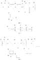
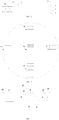
- an optical system 10 comprising a first light source 12, a first lens 16 and a light splitting module 40, wherein the light splitting module 40 comprises a first splitter 14, a second lens 18, a first camera 20 and a second camera 22.
- the first lens 16 is configured for receiving a first light beam from the first light source 12 and collimating the first light beam onto a sample 24, and for receiving and collimating a light beam from the sample 24.
- the second lens 18 is configured for focusing the collimated light beam from the first lens 16 to the first camera 20 and the second camera 22.
- the first splitter 14 is configured for splitting the focused light beam from the second lens 18 into a second light beam and a third light beam.
- the first camera 20 is configured for receiving the second light beam.
- the second camera 22 is configured for receiving the third light beam.
- the light beam is focused by the second lens 18, and then split by the splitter 14 into the second light beam and the third light beam.
- the use of optical elements and the length of the splitting optical path can be reduced, which shortens the total optical path of the optical system, and facilitates miniaturization and industrial manufacture of the optical system 10.
- the sample 24 may be a nucleic acid sample, and the nucleic acid sample may be placed in a reaction device, such as a flowcell.
- the first light source 12 may be a laser light source.
- the flowcell comprises a substrate, wherein the substrate is provided with a channel, and the substrate is provided with glass.
- sequencing is performed using a sequencing system of the optical system, the target nucleic acid, an enzyme, a nucleotide reagent or solution with a fluorescent label and others are mixed in the channel for reaction under a certain condition.
- the first light source 12 emits a laser onto a specific field of view of the flowcell through the first lens 16, and fluorophores in the field of view are excited to emit fluorescence.
- the fluorescence is focused to the first splitter 14 through the first lens 16 and the second lens 18.
- the first splitter 14 splits the converged fluorescence light beam into the second light beam and the third light beam.
- the first camera 20 receives the second light beam and the second camera 22 receives the third light beam to acquire a first image and a second image of the field of view respectively.
- the first light source 12 may comprise a first light emitter 13 and a third lens 15.
- the first light beam is a light beam emitted by the first light emitter 13 and collimated by the third lens 15.
- the first light beam is focused on a back focal plane of the first lens 16 by a fourth lens 17 and then collimated onto the sample 40 by the first lens 16.
- the first light source 12 further comprises a fiber coupler, for example, a single mode fiber coupler.
- the optical system 10 is a total internal reflection optical system.
- the collimated light beam (parallel light beam) passing through the first lens 16 is incident on the surface of the glass/cover-glass at an angle larger than the critical angle, thus generating total internal reflection and an evanescent field (evanescent wave) at the lower/bottom surface of the (flowcell) glass/cover-glass.
- the fluorescence emitted by the excited fluorescent molecule in the evanescent field is received by the first lens 16.
- the light beam received by the first lens 16 is the light beam emitted by the fluorophores of the sample 24.
- Image sensors of the first camera 20 and the second camera 22 may be CCDs or CMOSs.
- the image sensors of the first camera 20 and the second camera 22 are of the same type, for example, both CCDs or both CMOSs.
- the first splitter 14 may be a dichroic mirror.
- the second light beam is the transmitted light beam of the first splitter 14
- the third light beam is the reflected light beam of the first splitter 14.
- the first camera 20 and the second camera 22 are arranged at 90 degrees or 270 degrees. This facilitates disposing a plurality of cameras including the first camera 20 and the second camera 22 into the optical system within a limited space.
- the first splitter 14 has a first reflecting surface 26 at an included angle of 45 degrees to the horizontal plane. A part of the light beam incident on the first reflecting surface 26 in the horizontal direction is reflected and deflected by 90 degrees, reaching the second camera 22, and another part of the light beam incident on the first reflecting surface 26 in the horizontal direction passes through the first reflecting surface 26 and is incident on the first camera 20.
- the first camera 20 and the second camera 22 are arranged at 90 degrees in the clockwise direction or 270 degrees in the counterclockwise direction.
- the sample has two fluorescent labels, for example Cy3 and Atto647N, with emission bands of 550-620 nm and 650-750 nm, respectively (peaks of about 564 nm and 670 nm, respectively).
- the first splitter 14 is a dichroic mirror having a high transmittance for spectrum ranged 550-620 nm and a high reflectance for spectrum above 650 nm.
- the nucleotide reagents with the fluorescent labels include A, T, C and G reagents in separate containers.
- the four nucleotides have the same fluorescent label.
- each sequencing reaction includes four base extension reactions, which are sequential additions of the four nucleotides and the acquisitions of corresponding images.
- the four nucleotides are divided in two pairs, and the two nucleotides of each pair respectively carry a first fluorescent label and a second fluorescent label.
- the first fluorescent label and the second fluorescent label can be excited to emit different fluorescence.
- each sequencing reaction comprises two base extension reactions.
- the target nucleic acid, an enzyme, two nucleotide reagents or solutions with the first fluorescent label or the second fluorescent label and others are mixed in the channel for reaction under a certain condition.
- the first light source 12 simultaneously emits a first laser and a second laser onto a specific field of view on the flowcell through the first lens 16.
- the first fluorescent label and the second fluorescent label of the field of view are respectively excited by the first laser and the second laser to emit a first fluorescence and a second fluorescence.
- the first fluorescence and the second fluorescence are converged to the first splitter 14 (dichroic mirror) through the first lens 16 and the second lens 18.
- the dichroic mirror splits the converged first fluorescence and second fluorescence.
- the first fluorescence is focused onto an image plane of the first camera 20 and the second fluorescence is focused onto an image plane of the second camera 22, thereby giving a first image and a second image of the first fluorescence and the second fluorescence of the field of view, respectively.
- Base identification/sequencing is implemented based on the nucleotide addition sequence and information of the first image and the second image of different sequencing reactions.
- the four nucleotides carry fluorescent label a, fluorescent label b, fluorescent labels a-b and no label, respectively, wherein the fluorescent label a and the fluorescent label b can be excited to emit different fluorescences.
- each sequencing reaction comprises one base extension reaction.
- the target nucleic acid, an enzyme, the four nucleotide reagents or solutions and others are mixed in the channel for reaction under a certain condition.
- the first light source 12 simultaneously emits a first laser and a second laser onto a specific field of view of the flowcell through the first lens 16.
- the fluorescent labels in the field of view are excited by the first laser and the second laser to emit fluorescences.
- the fluorescences are converged to the first splitter 14 (dichroic mirror) through the first lens 16 and the second lens 18.
- the dichroic mirror splits the fluorescences into fluorescence from the fluorescent label a and fluorescence from the fluorescent label b.
- the fluorescence from the fluorescent label a is focused onto an image plane of the first camera 20 and the fluorescence from the fluorescent label b is focused onto an image plane of the second camera 22, thereby giving a first image and a second image of the field of view, respectively.
- Base identification/sequencing is implemented based on the first image and the second image of different sequencing reactions and by combining information of the first image and the second image of the same sequencing reaction.
- the first lens 16 comprises one or more lenses
- the second lens 18 comprises one or more lenses.
- the one or more lenses of the first lens 16 form an objective lens; and the one or more lenses of the second lens 18 form a tube lens.
- the first lens 16 comprises one or more lenses, or the second lens 18 comprises one or more lenses.
- the optical system 10 comprises a second splitter 28 configured for receiving the first light beam from the first light source 12 and deflecting the first light beam to the first lens 16, such that the first light beam is integrated into an optical path (imaging optical path) in which an optical axis of the first lens is positioned.
- the introduction of the second splitter 28 enables the arrangement of the first light source 12 outside the optical path in which the optical axis of the first lens 16 is positioned, allowing a compact and reasonable arrangement of elements of the optical system 10, facilitating the miniaturization and the industrial application of the optical system 10.
- the second splitter 28 is configured for deflecting the first light beam by 90 degrees.
- the position at which the first light source 12 is conveniently arranged comprises the relative positions of the components of the first light source.
- the optical system 10 comprises a third splitter 30 and an autofocus module 32.
- the autofocus module 32 is configured for emitting a fourth light beam, and for receiving the fourth light beam reflected by the surface of the glass wherein the sample 40 immobilized.
- the third splitter 30 is configured for receiving the fourth light beam and deflecting the fourth light beam to the first lens 16, and is further configured for receiving the fourth light beam reflected by the surface and deflecting the fourth light beam to the autofocus module 32.
- focusing(focus tracking) can be realized by using the autofocus module 32, and image acquisition can be realized by using the optical system 10.
- the autofocus module 32 comprises a second light source 34 and a receiver 36, wherein the second light source 34 is configured for emitting the fourth light beam to the third splitter 30, and the receiver 36 is configured for receiving the fourth light beam collimated by the first lens 16.
- the second light source 34 may be an infrared light source.
- the receiver 36 may be a photodiode.
- the second light source 34 emits the fourth light beam that is deflected to the first lens 16 by the third splitter 30 and then converged to the surface through the first lens 16.
- the fourth light beam reflected by the surface is collimated to the third splitter 30 by the first lens.
- a movable platform carrying the sample move the sample 24 toward or away from the first lens 16, to make the sample 24 in focus.
- the receiver 36 comprises a sensor, for example, a two-dimensional PSD sensor
- the second light source 34 comprises an LED (light source) and a mask positioned in front of the LED.
- the light emitted by the LED penetrates the mask to form a secondary source with a specific pattern.
- the secondary source with the specific pattern are deflected to the first lens 16 through the third splitter 30 and converged on the sample 24, and reflected to the sensor by the sample 24.
- the autofocus module 32 further comprises a signal processing module, wherein the sensor is connected to the signal processing module to acquire information of the secondary source through the signal processing module.
- the autofocus module 32 further comprises a signal output module for outputting the change of the information of the secondary source, such that the platform carrying the sample moves the sample to the focal plane of the imaging optical path (for example, a fluorescence optical path).
- the second light source 34 comprises a second light emitter 35 and a fifth lens 37, wherein the fourth light beam is a light beam emitted by the second light emitter 38 and collimated by the fifth lens 37.
- the fourth light beam reflected by the sample 40 is converged to the receiver 36 through the fifth lens 37.
- the second light beam is the focused light beam from the second lens 18 transmitting through the first splitter 14.
- the optical system 10 comprises a compensation lens 38 positioned between the first splitter 14 and the first camera 20, and configured for compensating astigmatism introduced by the second light beam.
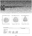
- the results of simulation with or without the first splitter 14 after the second lens 18 are respectively shown in FIGs. 5 and 6 .
- spots compared with spots (speckles/ diffraction spots) formed by the light beam only passing through the second lens 18, spots (speckles/ diffraction spots) formed by the light beam from the same field of view (FoV) passing through the second lens 18 and the first splitter 14 demonstrate significantly increased astigmatism.
- RMS radius root mean square radius
- the RMS radius is an important radius parameter, and is a square root of the quadratic sum of the coordinates of the speckles (with reference to the center point) divided by the number of speckles. This radius reflects the size of a typical speckle, so as to quantitatively reflect the resolution of the system.
- GEO radius may be used to represent the diameter of the diffuse spot. It is clear that, for the spots formed by the focusing of the light beams of the same field of view, FIG. 6 demonstrates a more significant astigmatism(astigmation) with a larger RMS radius compared with FIG. 5 .
- the inventor introduced the compensation lens 38 at any position between the second lens 18 and the first camera in the hope of compensating for the astigmatism caused by imaging after the transmission of the light beam.
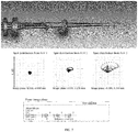
- the compensation lens 38 is introduced, as shown in FIG. 7 , for spots formed by the light beams from the same field of view, the spot size of FIG. 7 is significantly smaller than that of FIG. 6 , and at the same coordinates, the spot size of FIG. 7 approaches or even is smaller than that of FIG. 5 regarding the RMS radius.
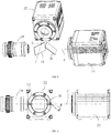
- the compensation lens 38 may be a parallel flat plate or a dichroic mirror. In the embodiments of FIGs. 8-10 , the compensation lens 38 is a dichroic mirror.
- the compensation lens 38 is at an included angle T of 45 degrees to a plane P perpendicular to the first splitter 14, and the plane P is defined by an optical axis A of the second light beam and an optical axis B of the third light beam.
- One embodiment of the present disclosure further provides a method for calibrating an optical system, wherein the optical system comprises a light splitting module 40 comprising a second lens 18, a first splitter 14, a first camera 20 and a second camera 22, and the second lens 18, the first splitter 14, and the first camera 20 are sequentially arranged along an optical axis of the second lens 18, the method comprising: emitting a collimated light beam to the second lens 18 using a collimator 50 comprising a target 42, the target 42 comprising one or more patterns; converging the collimated light beam to the first splitter 14 through the second lens 18 and splitting the converged light beam into a second light beam and a third light beam through the first splitter 14; receiving, by the first camera 20, the second light beam to acquire a first image of the patterns; receiving, by the second camera 22, the third light beam to acquire a second image of the patterns; and adjusting an angle and/or position of the first camera 20 and/or the second camera 22 to align the contrasts of the patterns
- the light splitting module 40 is adjusted as a module independent from the whole optical system 10, which eliminates the limit of adjusting the whole optical system, conveniently realizes the alignment of the lens included in the optical system and cameras to meet a specified requirement(e.g., make a plurality of cameras perpendicular to an optical axis), and is desirable for quickly calibrating an optical system comprising a splitting optical path.
- the collimator 50 further comprises a third light source 52, a ground glass 54(frosted glass/scattering glass) and an objective lens 56, wherein the third light source 52, the ground glass 54, the target 42 and the objective lens 56 are sequentially arranged, and light beam emitted by the third light source 52 sequentially passes through the ground glass 54, the target 42 and the objective lens 56 and penetrates to the second lens 18.
- the collimated light beam emitted by the collimator 50 is a parallel light beam, and the parallel light beam is incident to the first splitter 14 through the second lens 18 and is split into the second light beam and the third light beam.
- the patterns of the target 42 of the first image acquired by the first camera 20 are consistent in contrast
- the patterns of the target 42 of the second image acquired by the second camera 22 are consistent in contrast, indicating that the plane of the image sensor of the first camera 20 is perpendicular to the optical axis of the second lens 18, and the plane of the image sensor of the second camera 22 is perpendicular to the optical axis of the splitting optical path.
- the target 42 is a customized target with resolution line pairs designed by the inventor, as shown in FIG. 13 .
- the target with resolution line pairs comprises 5 patterns A1-A5 distributed at different positions.
- the contrasts are consistent for corresponding images of patterns A1-A5 of the target 42 acquired by the first camera 20 and the second camera 22, it is determined that the plane of the image sensor of the first camera 20 is perpendicular to the optical axis of the second lens 18, and the plane of the image sensor of the second camera 22 is perpendicular to the optical axis of the light beam reflected by the first splitter 14, which meets the requirements for sequencing image acquisition.
- the contrast of the images is determined to be consistent.
- the difference of two or more MTF values is less than 10%, preferably less than 5%, the MTF values are determined to be the same.
- the MTF values of the first image of the patterns A1-A5 are 0.80, 0.80, 0.80, 0.80 and 0.80, respectively, and the MTF values of the second image of the patterns A1-A5 are 0.80, 0.78, 0.78, 0.80 and 0.80, respectively.
- the contrast of the first image and the second image is determined to be consistent, and the optical system 10 is calibrated. The closer the MTF value approaches 1, the better the performance of the optical system 10 is.
- the target 42 has a plurality of patterns, as shown in FIG. 13 .
- the size(pattern area) of the first image or the second image is the size of a circle formed by the 5 patterns A1-A5.
- the optical system 10 it is required that the size of the first image and/or the second image is not less than forty percent of the size of the image actually required by the optical system 10 for imaging. As such, when imaging is performed by using the optical system 10, images of high quality can be acquired, and the requirements of sequencing are met.
- the size of the first image may refer to the size of an image formed by the distribution of the images of the plurality of patterns on the first camera 20.
- the size of the second image may refer to the size of an image formed by the distribution of the images of the plurality of patterns on the second camera 22.
- the size of the first image and/or the second image is not less than fifty percent of the size of the image actually imaged by the optical system.
- the light splitting module 40 further comprises a compensation lens 38, wherein the compensation lens 38 is positioned between the first splitter 14 and the first camera 20, and the first camera 20 receives the second light beam passing through the compensation lens 38 to acquire the first image.
- the imaging of the first image features good effect.
- a sequencing system 100 comprising a platform 116 for carrying a sample 40 and the optical system 10 according to any of the aforementioned embodiments.
- the sequencing system 100 comprises the optical system 10 with any of the aforementioned technical features and advantages, and is thus compact and is beneficial to the miniaturization and industrialization.
- the platform 116 is movable.
- the platform 116 moves the sample 40 relative to the optical system, for example, in a direction perpendicular to the optical axis of the first lens 16, or in a direction parallel to the optical axis of the first lens 16, or in a direction oblique to the optical axis of the first lens 16, such that different positions of the sample 40 are positioned directly under the first lens 16, and image acquisition on the sample 40 can be realized by the sequencing system 100 comprising the optical system 10, so as to perform the sequencing.
- sequencing system 100 in the embodiment of the present disclosure may comprise the optical system 10 according to any one of the aforementioned embodiments.
Landscapes
- Physics & Mathematics (AREA)
- General Physics & Mathematics (AREA)
- Optics & Photonics (AREA)
- Chemical & Material Sciences (AREA)
- Analytical Chemistry (AREA)
- Health & Medical Sciences (AREA)
- Nuclear Medicine, Radiotherapy & Molecular Imaging (AREA)
- Multimedia (AREA)
- Engineering & Computer Science (AREA)
- Life Sciences & Earth Sciences (AREA)
- Biochemistry (AREA)
- General Health & Medical Sciences (AREA)
- Immunology (AREA)
- Pathology (AREA)
- Investigating, Analyzing Materials By Fluorescence Or Luminescence (AREA)
- Microscoopes, Condenser (AREA)
Applications Claiming Priority (3)
| Application Number | Priority Date | Filing Date | Title |
|---|---|---|---|
| CN201822089550.1U CN209759461U (zh) | 2018-12-12 | 2018-12-12 | 光学系统和测序系统 |
| CN201811516793.7A CN111308726A (zh) | 2018-12-12 | 2018-12-12 | 光学系统、调校光学系统的方法和测序系统 |
| PCT/CN2019/109045 WO2020119226A1 (zh) | 2018-12-12 | 2019-09-29 | 光学系统、调校光学系统的方法和测序系统 |
Publications (2)
| Publication Number | Publication Date |
|---|---|
| EP3896146A1 true EP3896146A1 (de) | 2021-10-20 |
| EP3896146A4 EP3896146A4 (de) | 2022-01-19 |
Family
ID=71075255
Family Applications (1)
| Application Number | Title | Priority Date | Filing Date |
|---|---|---|---|
| EP19896106.2A Pending EP3896146A4 (de) | 2018-12-12 | 2019-09-29 | Optisches system, verfahren zur kalibrierung eines optischen systems und sequenzierungssystem |
Country Status (3)
| Country | Link |
|---|---|
| US (1) | US11874453B2 (de) |
| EP (1) | EP3896146A4 (de) |
| WO (1) | WO2020119226A1 (de) |
Families Citing this family (4)
| Publication number | Priority date | Publication date | Assignee | Title |
|---|---|---|---|---|
| DE102019105622B4 (de) * | 2019-03-06 | 2022-03-17 | Konrad Gmbh | Kollimator und Verfahren zum Testen einer Kamera |
| US11450083B2 (en) | 2019-09-27 | 2022-09-20 | Honeywell International Inc. | Dual-pattern optical 3D dimensioning |
| US11639846B2 (en) * | 2019-09-27 | 2023-05-02 | Honeywell International Inc. | Dual-pattern optical 3D dimensioning |
| CN112646703B (zh) * | 2020-12-29 | 2023-01-24 | 中国科学院长春光学精密机械与物理研究所 | 一种单分子荧光基因测序光学系统 |
Family Cites Families (12)
| Publication number | Priority date | Publication date | Assignee | Title |
|---|---|---|---|---|
| EP1576351A4 (de) | 2002-11-26 | 2010-06-23 | Univ Utah Res Found | Mikroporöse materialien; verfahren undartikel zur lokalisierung und quantifizierung von analyten |
| US7538890B2 (en) * | 2004-06-07 | 2009-05-26 | Fujinon Corporation | Wavefront-measuring interferometer apparatus, and light beam measurement apparatus and method thereof |
| WO2009042862A1 (en) | 2007-09-28 | 2009-04-02 | Illumina, Inc | Fluorescence excitation and detection system and method |
| TWI406025B (zh) | 2010-11-25 | 2013-08-21 | Ind Tech Res Inst | 自動聚焦裝置及方法 |
| CN103278934B (zh) | 2013-05-31 | 2017-03-29 | 中国科学院西安光学精密机械研究所 | 一种用于星载光学遥感器的焦面对接装置及方法 |
| JP6731854B2 (ja) * | 2014-01-10 | 2020-07-29 | グノティス ホールディング アーゲー | 高精度での単一分子解析 |
| CN104293648B (zh) * | 2014-09-29 | 2016-08-24 | 大族激光科技产业集团股份有限公司 | 基因测序光路系统 |
| CN105068232B (zh) | 2015-08-31 | 2017-11-24 | 福建师范大学 | 一种双通道结构光照明超分辨成像方法与装置 |
| CN105371757A (zh) * | 2015-10-27 | 2016-03-02 | 西安交通大学 | 一种差动式并行光学层析显微测量装置及方法 |
| CN108286936A (zh) * | 2017-04-18 | 2018-07-17 | 北京理工大学 | 激光微纳加工差动共焦在线监测一体化方法与装置 |
| CN209759461U (zh) * | 2018-12-12 | 2019-12-10 | 深圳市真迈生物科技有限公司 | 光学系统和测序系统 |
| WO2021057200A1 (zh) | 2019-09-24 | 2021-04-01 | 深圳市真迈生物科技有限公司 | 减振结构、检测系统和测序系统 |
-
2019
- 2019-09-29 EP EP19896106.2A patent/EP3896146A4/de active Pending
- 2019-09-29 WO PCT/CN2019/109045 patent/WO2020119226A1/zh not_active Ceased
- 2019-09-29 US US17/311,179 patent/US11874453B2/en active Active
Also Published As
| Publication number | Publication date |
|---|---|
| WO2020119226A1 (zh) | 2020-06-18 |
| EP3896146A4 (de) | 2022-01-19 |
| US20210373314A1 (en) | 2021-12-02 |
| US11874453B2 (en) | 2024-01-16 |
Similar Documents
| Publication | Publication Date | Title |
|---|---|---|
| US11874453B2 (en) | Optical system, method for calibrating optical system, and sequencing system | |
| US6355934B1 (en) | Imaging system for an optical scanner | |
| KR101022769B1 (ko) | 바이오칩용 광검출 장치 | |
| CN111308726A (zh) | 光学系统、调校光学系统的方法和测序系统 | |
| JP4945025B2 (ja) | 軸方向高解像度を有する走査型顕微鏡方法 | |
| CN120446068A (zh) | 测序拍照成像系统及测序拍照成像方法 | |
| US20260055442A1 (en) | Image based autofocus of optical systems | |
| CN101868752B (zh) | 用于利用线束照射样本的光学照射装置 | |
| CN111349553A (zh) | 一种基因测序仪光学系统 | |
| JP7850253B2 (ja) | 検出装置、遺伝子配列決定システム、および検出方法 | |
| CN209759461U (zh) | 光学系统和测序系统 | |
| AU2020366521B2 (en) | Virtual fiducials | |
| EP1157268B1 (de) | Abbildungssystem für optischen bildabtaster | |
| US20250076627A1 (en) | Imaging system, sequencing system, and imaging method | |
| EP4563982A1 (de) | Optomechanisches system und sequenzierungssystem | |
| HK40062282A (en) | Optical system, method for calibrating optical system, and sequencing system | |
| US12259310B2 (en) | Biological sample image collection device and gene sequencer | |
| CN218546517U (zh) | 一种接收装置及基因测序系统 | |
| CN220650468U (zh) | 光学成像装置和基因测序设备 | |
| CN222105348U (zh) | 光机系统及测序系统 | |
| KR20230048931A (ko) | 1차원 광센서를 이용한 2차원 형광 데이터 측정 장치 | |
| CN119959133A (zh) | 一种光学成像系统及一种生物分子检测系统 | |
| JP2008164719A (ja) | 走査型共焦点顕微鏡 | |
| HK40080170B (zh) | 生物样本图像采集装置及基因测序仪 |
Legal Events
| Date | Code | Title | Description |
|---|---|---|---|
| STAA | Information on the status of an ep patent application or granted ep patent |
Free format text: STATUS: THE INTERNATIONAL PUBLICATION HAS BEEN MADE |
|
| PUAI | Public reference made under article 153(3) epc to a published international application that has entered the european phase |
Free format text: ORIGINAL CODE: 0009012 |
|
| STAA | Information on the status of an ep patent application or granted ep patent |
Free format text: STATUS: REQUEST FOR EXAMINATION WAS MADE |
|
| 17P | Request for examination filed |
Effective date: 20210712 |
|
| AK | Designated contracting states |
Kind code of ref document: A1 Designated state(s): AL AT BE BG CH CY CZ DE DK EE ES FI FR GB GR HR HU IE IS IT LI LT LU LV MC MK MT NL NO PL PT RO RS SE SI SK SM TR |
|
| REG | Reference to a national code |
Ref country code: DE Ref legal event code: R079 Free format text: PREVIOUS MAIN CLASS: C12M0001340000 Ipc: G02B0021160000 |
|
| A4 | Supplementary search report drawn up and despatched |
Effective date: 20211220 |
|
| RIC1 | Information provided on ipc code assigned before grant |
Ipc: G01N 21/64 20060101ALN20211214BHEP Ipc: G02B 21/24 20060101ALI20211214BHEP Ipc: G02B 27/14 20060101ALI20211214BHEP Ipc: G02B 21/16 20060101AFI20211214BHEP |
|
| DAV | Request for validation of the european patent (deleted) | ||
| DAX | Request for extension of the european patent (deleted) | ||
| REG | Reference to a national code |
Ref country code: HK Ref legal event code: DE Ref document number: 40062282 Country of ref document: HK |
|
| STAA | Information on the status of an ep patent application or granted ep patent |
Free format text: STATUS: EXAMINATION IS IN PROGRESS |
|
| 17Q | First examination report despatched |
Effective date: 20240116 |
|
| GRAP | Despatch of communication of intention to grant a patent |
Free format text: ORIGINAL CODE: EPIDOSNIGR1 |
|
| STAA | Information on the status of an ep patent application or granted ep patent |
Free format text: STATUS: GRANT OF PATENT IS INTENDED |
|
| RIC1 | Information provided on ipc code assigned before grant |
Ipc: G02B 21/16 20060101AFI20260114BHEP Ipc: G02B 27/14 20060101ALI20260114BHEP Ipc: G02B 21/24 20060101ALI20260114BHEP Ipc: G01N 21/64 20060101ALN20260114BHEP |
|
| INTG | Intention to grant announced |
Effective date: 20260130 |
|
| GRAJ | Information related to disapproval of communication of intention to grant by the applicant or resumption of examination proceedings by the epo deleted |
Free format text: ORIGINAL CODE: EPIDOSDIGR1 |
|
| STAA | Information on the status of an ep patent application or granted ep patent |
Free format text: STATUS: EXAMINATION IS IN PROGRESS |