EP3896189A1 - Verfahren zur beschichtung von substraten mit öffnung(en) - Google Patents
Verfahren zur beschichtung von substraten mit öffnung(en) Download PDFInfo
- Publication number
- EP3896189A1 EP3896189A1 EP21166107.9A EP21166107A EP3896189A1 EP 3896189 A1 EP3896189 A1 EP 3896189A1 EP 21166107 A EP21166107 A EP 21166107A EP 3896189 A1 EP3896189 A1 EP 3896189A1
- Authority
- EP
- European Patent Office
- Prior art keywords
- coating
- hollow member
- aperture
- component
- space
- Prior art date
- Legal status (The legal status is an assumption and is not a legal conclusion. Google has not performed a legal analysis and makes no representation as to the accuracy of the status listed.)
- Pending
Links
Images


Classifications
-
- B—PERFORMING OPERATIONS; TRANSPORTING
- B05—SPRAYING OR ATOMISING IN GENERAL; APPLYING FLUENT MATERIALS TO SURFACES, IN GENERAL
- B05D—PROCESSES FOR APPLYING FLUENT MATERIALS TO SURFACES, IN GENERAL
- B05D7/00—Processes, other than flocking, specially adapted for applying liquids or other fluent materials to particular surfaces or for applying particular liquids or other fluent materials
- B05D7/14—Processes, other than flocking, specially adapted for applying liquids or other fluent materials to particular surfaces or for applying particular liquids or other fluent materials to metal, e.g. car bodies
-
- C—CHEMISTRY; METALLURGY
- C23—COATING METALLIC MATERIAL; COATING MATERIAL WITH METALLIC MATERIAL; CHEMICAL SURFACE TREATMENT; DIFFUSION TREATMENT OF METALLIC MATERIAL; COATING BY VACUUM EVAPORATION, BY SPUTTERING, BY ION IMPLANTATION OR BY CHEMICAL VAPOUR DEPOSITION, IN GENERAL; INHIBITING CORROSION OF METALLIC MATERIAL OR INCRUSTATION IN GENERAL
- C23C—COATING METALLIC MATERIAL; COATING MATERIAL WITH METALLIC MATERIAL; SURFACE TREATMENT OF METALLIC MATERIAL BY DIFFUSION INTO THE SURFACE, BY CHEMICAL CONVERSION OR SUBSTITUTION; COATING BY VACUUM EVAPORATION, BY SPUTTERING, BY ION IMPLANTATION OR BY CHEMICAL VAPOUR DEPOSITION, IN GENERAL
- C23C4/00—Coating by spraying the coating material in the molten state, e.g. by flame, plasma or electric discharge
- C23C4/02—Pretreatment of the material to be coated, e.g. for coating on selected surface areas
-
- C—CHEMISTRY; METALLURGY
- C23—COATING METALLIC MATERIAL; COATING MATERIAL WITH METALLIC MATERIAL; CHEMICAL SURFACE TREATMENT; DIFFUSION TREATMENT OF METALLIC MATERIAL; COATING BY VACUUM EVAPORATION, BY SPUTTERING, BY ION IMPLANTATION OR BY CHEMICAL VAPOUR DEPOSITION, IN GENERAL; INHIBITING CORROSION OF METALLIC MATERIAL OR INCRUSTATION IN GENERAL
- C23C—COATING METALLIC MATERIAL; COATING MATERIAL WITH METALLIC MATERIAL; SURFACE TREATMENT OF METALLIC MATERIAL BY DIFFUSION INTO THE SURFACE, BY CHEMICAL CONVERSION OR SUBSTITUTION; COATING BY VACUUM EVAPORATION, BY SPUTTERING, BY ION IMPLANTATION OR BY CHEMICAL VAPOUR DEPOSITION, IN GENERAL
- C23C4/00—Coating by spraying the coating material in the molten state, e.g. by flame, plasma or electric discharge
- C23C4/04—Coating by spraying the coating material in the molten state, e.g. by flame, plasma or electric discharge characterised by the coating material
- C23C4/10—Oxides, borides, carbides, nitrides or silicides; Mixtures thereof
- C23C4/11—Oxides
-
- B—PERFORMING OPERATIONS; TRANSPORTING
- B05—SPRAYING OR ATOMISING IN GENERAL; APPLYING FLUENT MATERIALS TO SURFACES, IN GENERAL
- B05D—PROCESSES FOR APPLYING FLUENT MATERIALS TO SURFACES, IN GENERAL
- B05D1/00—Processes for applying liquids or other fluent materials
- B05D1/02—Processes for applying liquids or other fluent materials performed by spraying
-
- B—PERFORMING OPERATIONS; TRANSPORTING
- B32—LAYERED PRODUCTS
- B32B—LAYERED PRODUCTS, i.e. PRODUCTS BUILT-UP OF STRATA OF FLAT OR NON-FLAT, e.g. CELLULAR OR HONEYCOMB, FORM
- B32B3/00—Layered products comprising a layer with external or internal discontinuities or unevennesses, or a layer of non-planar shape; Layered products comprising a layer having particular features of form
- B32B3/26—Layered products comprising a layer with external or internal discontinuities or unevennesses, or a layer of non-planar shape; Layered products comprising a layer having particular features of form characterised by a particular shape of the outline of the cross-section of a continuous layer; characterised by a layer with cavities or internal voids ; characterised by an apertured layer
- B32B3/266—Layered products comprising a layer with external or internal discontinuities or unevennesses, or a layer of non-planar shape; Layered products comprising a layer having particular features of form characterised by a particular shape of the outline of the cross-section of a continuous layer; characterised by a layer with cavities or internal voids ; characterised by an apertured layer characterised by an apertured layer, the apertures going through the whole thickness of the layer, e.g. expanded metal, perforated layer, slit layer regular cells B32B3/12
-
- B—PERFORMING OPERATIONS; TRANSPORTING
- B33—ADDITIVE MANUFACTURING TECHNOLOGY
- B33Y—ADDITIVE MANUFACTURING, i.e. MANUFACTURING OF THREE-DIMENSIONAL [3D] OBJECTS BY ADDITIVE DEPOSITION, ADDITIVE AGGLOMERATION OR ADDITIVE LAYERING, e.g. BY 3D PRINTING, STEREOLITHOGRAPHY OR SELECTIVE LASER SINTERING
- B33Y40/00—Auxiliary operations or equipment, e.g. for material handling
- B33Y40/20—Post-treatment, e.g. curing, coating or polishing
-
- B—PERFORMING OPERATIONS; TRANSPORTING
- B33—ADDITIVE MANUFACTURING TECHNOLOGY
- B33Y—ADDITIVE MANUFACTURING, i.e. MANUFACTURING OF THREE-DIMENSIONAL [3D] OBJECTS BY ADDITIVE DEPOSITION, ADDITIVE AGGLOMERATION OR ADDITIVE LAYERING, e.g. BY 3D PRINTING, STEREOLITHOGRAPHY OR SELECTIVE LASER SINTERING
- B33Y80/00—Products made by additive manufacturing
-
- C—CHEMISTRY; METALLURGY
- C23—COATING METALLIC MATERIAL; COATING MATERIAL WITH METALLIC MATERIAL; CHEMICAL SURFACE TREATMENT; DIFFUSION TREATMENT OF METALLIC MATERIAL; COATING BY VACUUM EVAPORATION, BY SPUTTERING, BY ION IMPLANTATION OR BY CHEMICAL VAPOUR DEPOSITION, IN GENERAL; INHIBITING CORROSION OF METALLIC MATERIAL OR INCRUSTATION IN GENERAL
- C23C—COATING METALLIC MATERIAL; COATING MATERIAL WITH METALLIC MATERIAL; SURFACE TREATMENT OF METALLIC MATERIAL BY DIFFUSION INTO THE SURFACE, BY CHEMICAL CONVERSION OR SUBSTITUTION; COATING BY VACUUM EVAPORATION, BY SPUTTERING, BY ION IMPLANTATION OR BY CHEMICAL VAPOUR DEPOSITION, IN GENERAL
- C23C14/00—Coating by vacuum evaporation, by sputtering or by ion implantation of the coating forming material
- C23C14/04—Coating on selected surface areas, e.g. using masks
- C23C14/042—Coating on selected surface areas, e.g. using masks using masks
-
- C—CHEMISTRY; METALLURGY
- C23—COATING METALLIC MATERIAL; COATING MATERIAL WITH METALLIC MATERIAL; CHEMICAL SURFACE TREATMENT; DIFFUSION TREATMENT OF METALLIC MATERIAL; COATING BY VACUUM EVAPORATION, BY SPUTTERING, BY ION IMPLANTATION OR BY CHEMICAL VAPOUR DEPOSITION, IN GENERAL; INHIBITING CORROSION OF METALLIC MATERIAL OR INCRUSTATION IN GENERAL
- C23C—COATING METALLIC MATERIAL; COATING MATERIAL WITH METALLIC MATERIAL; SURFACE TREATMENT OF METALLIC MATERIAL BY DIFFUSION INTO THE SURFACE, BY CHEMICAL CONVERSION OR SUBSTITUTION; COATING BY VACUUM EVAPORATION, BY SPUTTERING, BY ION IMPLANTATION OR BY CHEMICAL VAPOUR DEPOSITION, IN GENERAL
- C23C14/00—Coating by vacuum evaporation, by sputtering or by ion implantation of the coating forming material
- C23C14/06—Coating by vacuum evaporation, by sputtering or by ion implantation of the coating forming material characterised by the coating material
- C23C14/08—Oxides
-
- C—CHEMISTRY; METALLURGY
- C23—COATING METALLIC MATERIAL; COATING MATERIAL WITH METALLIC MATERIAL; CHEMICAL SURFACE TREATMENT; DIFFUSION TREATMENT OF METALLIC MATERIAL; COATING BY VACUUM EVAPORATION, BY SPUTTERING, BY ION IMPLANTATION OR BY CHEMICAL VAPOUR DEPOSITION, IN GENERAL; INHIBITING CORROSION OF METALLIC MATERIAL OR INCRUSTATION IN GENERAL
- C23C—COATING METALLIC MATERIAL; COATING MATERIAL WITH METALLIC MATERIAL; SURFACE TREATMENT OF METALLIC MATERIAL BY DIFFUSION INTO THE SURFACE, BY CHEMICAL CONVERSION OR SUBSTITUTION; COATING BY VACUUM EVAPORATION, BY SPUTTERING, BY ION IMPLANTATION OR BY CHEMICAL VAPOUR DEPOSITION, IN GENERAL
- C23C14/00—Coating by vacuum evaporation, by sputtering or by ion implantation of the coating forming material
- C23C14/22—Coating by vacuum evaporation, by sputtering or by ion implantation of the coating forming material characterised by the process of coating
- C23C14/24—Vacuum evaporation
- C23C14/28—Vacuum evaporation by wave energy or particle radiation
- C23C14/30—Vacuum evaporation by wave energy or particle radiation by electron bombardment
-
- C—CHEMISTRY; METALLURGY
- C23—COATING METALLIC MATERIAL; COATING MATERIAL WITH METALLIC MATERIAL; CHEMICAL SURFACE TREATMENT; DIFFUSION TREATMENT OF METALLIC MATERIAL; COATING BY VACUUM EVAPORATION, BY SPUTTERING, BY ION IMPLANTATION OR BY CHEMICAL VAPOUR DEPOSITION, IN GENERAL; INHIBITING CORROSION OF METALLIC MATERIAL OR INCRUSTATION IN GENERAL
- C23C—COATING METALLIC MATERIAL; COATING MATERIAL WITH METALLIC MATERIAL; SURFACE TREATMENT OF METALLIC MATERIAL BY DIFFUSION INTO THE SURFACE, BY CHEMICAL CONVERSION OR SUBSTITUTION; COATING BY VACUUM EVAPORATION, BY SPUTTERING, BY ION IMPLANTATION OR BY CHEMICAL VAPOUR DEPOSITION, IN GENERAL
- C23C4/00—Coating by spraying the coating material in the molten state, e.g. by flame, plasma or electric discharge
- C23C4/04—Coating by spraying the coating material in the molten state, e.g. by flame, plasma or electric discharge characterised by the coating material
- C23C4/06—Metallic material
-
- C—CHEMISTRY; METALLURGY
- C23—COATING METALLIC MATERIAL; COATING MATERIAL WITH METALLIC MATERIAL; CHEMICAL SURFACE TREATMENT; DIFFUSION TREATMENT OF METALLIC MATERIAL; COATING BY VACUUM EVAPORATION, BY SPUTTERING, BY ION IMPLANTATION OR BY CHEMICAL VAPOUR DEPOSITION, IN GENERAL; INHIBITING CORROSION OF METALLIC MATERIAL OR INCRUSTATION IN GENERAL
- C23C—COATING METALLIC MATERIAL; COATING MATERIAL WITH METALLIC MATERIAL; SURFACE TREATMENT OF METALLIC MATERIAL BY DIFFUSION INTO THE SURFACE, BY CHEMICAL CONVERSION OR SUBSTITUTION; COATING BY VACUUM EVAPORATION, BY SPUTTERING, BY ION IMPLANTATION OR BY CHEMICAL VAPOUR DEPOSITION, IN GENERAL
- C23C4/00—Coating by spraying the coating material in the molten state, e.g. by flame, plasma or electric discharge
- C23C4/04—Coating by spraying the coating material in the molten state, e.g. by flame, plasma or electric discharge characterised by the coating material
- C23C4/10—Oxides, borides, carbides, nitrides or silicides; Mixtures thereof
-
- C—CHEMISTRY; METALLURGY
- C23—COATING METALLIC MATERIAL; COATING MATERIAL WITH METALLIC MATERIAL; CHEMICAL SURFACE TREATMENT; DIFFUSION TREATMENT OF METALLIC MATERIAL; COATING BY VACUUM EVAPORATION, BY SPUTTERING, BY ION IMPLANTATION OR BY CHEMICAL VAPOUR DEPOSITION, IN GENERAL; INHIBITING CORROSION OF METALLIC MATERIAL OR INCRUSTATION IN GENERAL
- C23C—COATING METALLIC MATERIAL; COATING MATERIAL WITH METALLIC MATERIAL; SURFACE TREATMENT OF METALLIC MATERIAL BY DIFFUSION INTO THE SURFACE, BY CHEMICAL CONVERSION OR SUBSTITUTION; COATING BY VACUUM EVAPORATION, BY SPUTTERING, BY ION IMPLANTATION OR BY CHEMICAL VAPOUR DEPOSITION, IN GENERAL
- C23C4/00—Coating by spraying the coating material in the molten state, e.g. by flame, plasma or electric discharge
- C23C4/12—Coating by spraying the coating material in the molten state, e.g. by flame, plasma or electric discharge characterised by the method of spraying
- C23C4/129—Flame spraying
-
- C—CHEMISTRY; METALLURGY
- C23—COATING METALLIC MATERIAL; COATING MATERIAL WITH METALLIC MATERIAL; CHEMICAL SURFACE TREATMENT; DIFFUSION TREATMENT OF METALLIC MATERIAL; COATING BY VACUUM EVAPORATION, BY SPUTTERING, BY ION IMPLANTATION OR BY CHEMICAL VAPOUR DEPOSITION, IN GENERAL; INHIBITING CORROSION OF METALLIC MATERIAL OR INCRUSTATION IN GENERAL
- C23C—COATING METALLIC MATERIAL; COATING MATERIAL WITH METALLIC MATERIAL; SURFACE TREATMENT OF METALLIC MATERIAL BY DIFFUSION INTO THE SURFACE, BY CHEMICAL CONVERSION OR SUBSTITUTION; COATING BY VACUUM EVAPORATION, BY SPUTTERING, BY ION IMPLANTATION OR BY CHEMICAL VAPOUR DEPOSITION, IN GENERAL
- C23C4/00—Coating by spraying the coating material in the molten state, e.g. by flame, plasma or electric discharge
- C23C4/12—Coating by spraying the coating material in the molten state, e.g. by flame, plasma or electric discharge characterised by the method of spraying
- C23C4/134—Plasma spraying
-
- F—MECHANICAL ENGINEERING; LIGHTING; HEATING; WEAPONS; BLASTING
- F01—MACHINES OR ENGINES IN GENERAL; ENGINE PLANTS IN GENERAL; STEAM ENGINES
- F01D—NON-POSITIVE DISPLACEMENT MACHINES OR ENGINES, e.g. STEAM TURBINES
- F01D5/00—Blades; Blade-carrying members; Heating, heat-insulating, cooling or antivibration means on the blades or the members
- F01D5/12—Blades
- F01D5/14—Form or construction
- F01D5/18—Hollow blades, i.e. blades with cooling or heating channels or cavities; Heating, heat-insulating or cooling means on blades
- F01D5/186—Film cooling
-
- F—MECHANICAL ENGINEERING; LIGHTING; HEATING; WEAPONS; BLASTING
- F01—MACHINES OR ENGINES IN GENERAL; ENGINE PLANTS IN GENERAL; STEAM ENGINES
- F01D—NON-POSITIVE DISPLACEMENT MACHINES OR ENGINES, e.g. STEAM TURBINES
- F01D5/00—Blades; Blade-carrying members; Heating, heat-insulating, cooling or antivibration means on the blades or the members
- F01D5/12—Blades
- F01D5/28—Selecting particular materials; Particular measures relating thereto; Measures against erosion or corrosion
- F01D5/288—Protective coatings for blades
-
- F—MECHANICAL ENGINEERING; LIGHTING; HEATING; WEAPONS; BLASTING
- F01—MACHINES OR ENGINES IN GENERAL; ENGINE PLANTS IN GENERAL; STEAM ENGINES
- F01D—NON-POSITIVE DISPLACEMENT MACHINES OR ENGINES, e.g. STEAM TURBINES
- F01D9/00—Stators
- F01D9/02—Nozzles; Nozzle boxes; Stator blades; Guide conduits, e.g. individual nozzles
- F01D9/023—Transition ducts between combustor cans and first stage of the turbine in gas-turbine engines; their cooling or sealings
-
- F—MECHANICAL ENGINEERING; LIGHTING; HEATING; WEAPONS; BLASTING
- F02—COMBUSTION ENGINES; HOT-GAS OR COMBUSTION-PRODUCT ENGINE PLANTS
- F02C—GAS-TURBINE PLANTS; AIR INTAKES FOR JET-PROPULSION PLANTS; CONTROLLING FUEL SUPPLY IN AIR-BREATHING JET-PROPULSION PLANTS
- F02C7/00—Features, components parts, details or accessories, not provided for in, or of interest apart form groups F02C1/00 - F02C6/00; Air intakes for jet-propulsion plants
- F02C7/22—Fuel supply systems
-
- F—MECHANICAL ENGINEERING; LIGHTING; HEATING; WEAPONS; BLASTING
- F23—COMBUSTION APPARATUS; COMBUSTION PROCESSES
- F23R—GENERATING COMBUSTION PRODUCTS OF HIGH PRESSURE OR HIGH VELOCITY, e.g. GAS-TURBINE COMBUSTION CHAMBERS
- F23R3/00—Continuous combustion chambers using liquid or gaseous fuel
- F23R3/005—Combined with pressure or heat exchangers
-
- F—MECHANICAL ENGINEERING; LIGHTING; HEATING; WEAPONS; BLASTING
- F23—COMBUSTION APPARATUS; COMBUSTION PROCESSES
- F23R—GENERATING COMBUSTION PRODUCTS OF HIGH PRESSURE OR HIGH VELOCITY, e.g. GAS-TURBINE COMBUSTION CHAMBERS
- F23R3/00—Continuous combustion chambers using liquid or gaseous fuel
- F23R3/007—Continuous combustion chambers using liquid or gaseous fuel constructed mainly of ceramic components
-
- B—PERFORMING OPERATIONS; TRANSPORTING
- B05—SPRAYING OR ATOMISING IN GENERAL; APPLYING FLUENT MATERIALS TO SURFACES, IN GENERAL
- B05D—PROCESSES FOR APPLYING FLUENT MATERIALS TO SURFACES, IN GENERAL
- B05D1/00—Processes for applying liquids or other fluent materials
- B05D1/32—Processes for applying liquids or other fluent materials using means for protecting parts of a surface not to be coated, e.g. using stencils, resists
-
- B—PERFORMING OPERATIONS; TRANSPORTING
- B22—CASTING; POWDER METALLURGY
- B22F—WORKING METALLIC POWDER; MANUFACTURE OF ARTICLES FROM METALLIC POWDER; MAKING METALLIC POWDER; APPARATUS OR DEVICES SPECIALLY ADAPTED FOR METALLIC POWDER
- B22F2998/00—Supplementary information concerning processes or compositions relating to powder metallurgy
- B22F2998/10—Processes characterised by the sequence of their steps
-
- B—PERFORMING OPERATIONS; TRANSPORTING
- B23—MACHINE TOOLS; METAL-WORKING NOT OTHERWISE PROVIDED FOR
- B23P—METAL-WORKING NOT OTHERWISE PROVIDED FOR; COMBINED OPERATIONS; UNIVERSAL MACHINE TOOLS
- B23P2700/00—Indexing scheme relating to the articles being treated, e.g. manufactured, repaired, assembled, connected or other operations covered in the subgroups
- B23P2700/06—Cooling passages of turbine components, e.g. unblocking or preventing blocking of cooling passages of turbine components
-
- C—CHEMISTRY; METALLURGY
- C23—COATING METALLIC MATERIAL; COATING MATERIAL WITH METALLIC MATERIAL; CHEMICAL SURFACE TREATMENT; DIFFUSION TREATMENT OF METALLIC MATERIAL; COATING BY VACUUM EVAPORATION, BY SPUTTERING, BY ION IMPLANTATION OR BY CHEMICAL VAPOUR DEPOSITION, IN GENERAL; INHIBITING CORROSION OF METALLIC MATERIAL OR INCRUSTATION IN GENERAL
- C23C—COATING METALLIC MATERIAL; COATING MATERIAL WITH METALLIC MATERIAL; SURFACE TREATMENT OF METALLIC MATERIAL BY DIFFUSION INTO THE SURFACE, BY CHEMICAL CONVERSION OR SUBSTITUTION; COATING BY VACUUM EVAPORATION, BY SPUTTERING, BY ION IMPLANTATION OR BY CHEMICAL VAPOUR DEPOSITION, IN GENERAL
- C23C8/00—Solid state diffusion of only non-metal elements into metallic material surfaces; Chemical surface treatment of metallic material by reaction of the surface with a reactive gas, leaving reaction products of surface material in the coating, e.g. conversion coatings, passivation of metals
- C23C8/04—Treatment of selected surface areas, e.g. using masks
-
- F—MECHANICAL ENGINEERING; LIGHTING; HEATING; WEAPONS; BLASTING
- F05—INDEXING SCHEMES RELATING TO ENGINES OR PUMPS IN VARIOUS SUBCLASSES OF CLASSES F01-F04
- F05D—INDEXING SCHEME FOR ASPECTS RELATING TO NON-POSITIVE-DISPLACEMENT MACHINES OR ENGINES, GAS-TURBINES OR JET-PROPULSION PLANTS
- F05D2230/00—Manufacture
- F05D2230/80—Repairing, retrofitting or upgrading methods
-
- F—MECHANICAL ENGINEERING; LIGHTING; HEATING; WEAPONS; BLASTING
- F05—INDEXING SCHEMES RELATING TO ENGINES OR PUMPS IN VARIOUS SUBCLASSES OF CLASSES F01-F04
- F05D—INDEXING SCHEME FOR ASPECTS RELATING TO NON-POSITIVE-DISPLACEMENT MACHINES OR ENGINES, GAS-TURBINES OR JET-PROPULSION PLANTS
- F05D2230/00—Manufacture
- F05D2230/90—Coating; Surface treatment
-
- F—MECHANICAL ENGINEERING; LIGHTING; HEATING; WEAPONS; BLASTING
- F05—INDEXING SCHEMES RELATING TO ENGINES OR PUMPS IN VARIOUS SUBCLASSES OF CLASSES F01-F04
- F05D—INDEXING SCHEME FOR ASPECTS RELATING TO NON-POSITIVE-DISPLACEMENT MACHINES OR ENGINES, GAS-TURBINES OR JET-PROPULSION PLANTS
- F05D2240/00—Components
- F05D2240/10—Stators
- F05D2240/11—Shroud seal segments
-
- F—MECHANICAL ENGINEERING; LIGHTING; HEATING; WEAPONS; BLASTING
- F23—COMBUSTION APPARATUS; COMBUSTION PROCESSES
- F23R—GENERATING COMBUSTION PRODUCTS OF HIGH PRESSURE OR HIGH VELOCITY, e.g. GAS-TURBINE COMBUSTION CHAMBERS
- F23R2900/00—Special features of, or arrangements for continuous combustion chambers; Combustion processes therefor
- F23R2900/00018—Manufacturing combustion chamber liners or subparts
-
- F—MECHANICAL ENGINEERING; LIGHTING; HEATING; WEAPONS; BLASTING
- F23—COMBUSTION APPARATUS; COMBUSTION PROCESSES
- F23R—GENERATING COMBUSTION PRODUCTS OF HIGH PRESSURE OR HIGH VELOCITY, e.g. GAS-TURBINE COMBUSTION CHAMBERS
- F23R2900/00—Special features of, or arrangements for continuous combustion chambers; Combustion processes therefor
- F23R2900/03042—Film cooled combustion chamber walls or domes
-
- Y—GENERAL TAGGING OF NEW TECHNOLOGICAL DEVELOPMENTS; GENERAL TAGGING OF CROSS-SECTIONAL TECHNOLOGIES SPANNING OVER SEVERAL SECTIONS OF THE IPC; TECHNICAL SUBJECTS COVERED BY FORMER USPC CROSS-REFERENCE ART COLLECTIONS [XRACs] AND DIGESTS
- Y02—TECHNOLOGIES OR APPLICATIONS FOR MITIGATION OR ADAPTATION AGAINST CLIMATE CHANGE
- Y02P—CLIMATE CHANGE MITIGATION TECHNOLOGIES IN THE PRODUCTION OR PROCESSING OF GOODS
- Y02P10/00—Technologies related to metal processing
- Y02P10/25—Process efficiency
-
- Y—GENERAL TAGGING OF NEW TECHNOLOGICAL DEVELOPMENTS; GENERAL TAGGING OF CROSS-SECTIONAL TECHNOLOGIES SPANNING OVER SEVERAL SECTIONS OF THE IPC; TECHNICAL SUBJECTS COVERED BY FORMER USPC CROSS-REFERENCE ART COLLECTIONS [XRACs] AND DIGESTS
- Y10—TECHNICAL SUBJECTS COVERED BY FORMER USPC
- Y10T—TECHNICAL SUBJECTS COVERED BY FORMER US CLASSIFICATION
- Y10T428/00—Stock material or miscellaneous articles
- Y10T428/24—Structurally defined web or sheet [e.g., overall dimension, etc.]
- Y10T428/24273—Structurally defined web or sheet [e.g., overall dimension, etc.] including aperture
- Y10T428/24322—Composite web or sheet
Definitions
- the disclosure relates generally to methods for coating substrates.
- the present disclosure is directed to coating methods for selectively coating a substrate that includes apertures, and a coated substrate that includes apertures formed by the coating methods.
- turbines When turbines are used on aircraft or for power generation, they are typically run at a temperature as high as possible, for increased operating efficiency. Since high temperatures can damage the alloys used for the components, a variety of approaches have been used to raise the operating temperature of metal components.
- One approach calls for the incorporation of internal cooling channels in the component, through which cool air is forced during engine operation. Apertures or cooling holes can be formed in the substrate by techniques such as water jet processing and/or electrical discharge machining (EDM). Cooling air (usually provided by the engine's compressor) is fed through the holes from the cooler side to the hot side of a component wall. As long as the holes remain clear, the rushing air will assist in lowering the temperature of the hot metal surface and preventing melting or other degradation of the component.
- EDM electrical discharge machining
- TBC thermal barrier coating
- EBC environmental barrier coating
- a TBC is usually ceramic-based.
- Coating systems frequently also include a bond coat which is placed between the ceramic coating and the substrate to improve adhesion.
- Use of TBC's in conjunction with cooling holes is sometimes an effective means for protecting an engine part.
- incorporation of both systems can be very difficult.
- cooling holes sometimes cannot be formed in the engine part after a TBC has been applied, since lasers usually cannot effectively penetrate both ceramic material and metal to form the pattern of holes and may possibly crack a TBC. If cooling holes are formed prior to the application of a coating system, they may become covered and at least partially obstructed when a coating is applied.
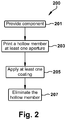
- a first aspect of the disclosure provides a coating method for a component with at least one aperture.
- the coating method includes providing a component having at least one aperture formed in a surface thereof; additively manufacturing a hollow member on a portion of the surface to define a space above each aperture, the portion of the surface being adjacent to the aperture, the hollow member having an inner peripheral geometry complementary to a peripheral geometry at least one of aperture; applying at least one coating over the surface of the component and around the hollow member to form an applied coating having an applied coating thickness; and removing at least a portion of the hollow member to make a top portion of the hollow member coplanar with the applied coating to expose the space through the applied coating; wherein a lower portion of the hollow member remains to define the space through the applied coating.
- a second aspect of the disclosure provides a coated component.
- the component includes a surface; at least one aperture formed in the surface; a coating layer on the surface, the coating layer including: at least one hollow member additively manufactured on the surface extending from the surface to a top surface, each hollow member defining a space above a respective one of the at least one aperture, a perimeter of the hollow member being coincident with each at least one aperture and having an inner peripheral geometry complementary to a peripheral geometry the respective one of the at least one of the aperture; a coating material sprayed on the surface and around the hollow member, the coating material having a top surface coplanar with a portion of the hollow member after portions of at least one of the hollow member is removed.
- downstream and upstream are terms that indicate a direction relative to the flow of a fluid, such as the working fluid through the turbine engine or, for example, the flow of air through the combustor or coolant through one of the turbine's component systems.
- the term “downstream” corresponds to the direction of flow of the fluid, and the term “upstream” refers to the direction opposite to the flow.
- forward and aft without any further specificity, refer to directions, with “forward” referring to the front or compressor end of the engine, and “aft” referring to the rearward or turbine end of the engine.
- radial refers to movement or position perpendicular to an axis. For example, if a first component resides closer to the axis than a second component, it will be stated herein that the first component is “radially inward” or “inboard” of the second component. If, on the other hand, the first component resides further from the axis than the second component, it may be stated herein that the first component is “radially outward” or “outboard” of the second component.
- axial refers to movement or position parallel to an axis.
- circumferential refers to movement or position around an axis. It will be appreciated that such terms may be applied in relation to the center axis of the turbine.
- the disclosure provides methods for coating components.
- the present disclosure is directed to coating methods for selectively coating a component that includes apertures, and a coated component that includes apertures formed by coating methods.
- a component 100 includes any suitable component having at least one aperture 109 formed therein.
- component 100 includes any suitable component used in applications that undergo temperature changes, such as, but not limited to, power generation systems (e.g., gas turbines, jet turbines, and other turbine assemblies).
- power generation systems e.g., gas turbines, jet turbines, and other turbine assemblies.
- Suitable illustrative components 100 include, but are not limited to: a nozzle, a blade, a vane, a shroud, a bucket, a transition piece, a liner, or a combination thereof.
- Aperture 109 includes any opening formed in an external surface 102 of component 100, such as, but not limited to: a cooling hole (e.g., a trench cooling hole, a diffuser shape cooling hole, a straight cooling hole, an angled cooling hole), an opening to provide fuel flow, or a combination thereof, and other cooling hole configurations now known or hereinafter developed.
- a cooling hole e.g., a trench cooling hole, a diffuser shape cooling hole, a straight cooling hole, an angled cooling hole
- an opening to provide fuel flow or a combination thereof, and other cooling hole configurations now known or hereinafter developed.
- component 100 is illustratively shown as a turbine blade having an airfoil section 103, a platform section 105, and a dovetail section 107.
- Airfoil section 103 has a plurality of apertures 109 functioning as cooling holes formed therein.
- component 100 is fabricated from a high temperature oxidation and corrosion resistant alloy with high temperature strength, such as a nickel-based, cobalt-based, or iron-based superalloy.
- component 100 includes a coating 400 ( FIG. 4 ) applied over an external surface 102 of the component.
- Coating 400 can include any suitable coating covering at least a portion of external surface 102 and/or providing protection (e.g., increased heat tolerance, increased corrosion resistance) to external surface 102, such as, but not limited to, a bond coat, a thermal barrier coating (TBC), an environmental barrier coating (EBC), or a combination thereof, or other coatings now known or hereinafter developed.
- TBC thermal barrier coating
- EBC environmental barrier coating
- Suitable examples of the bond coat include, but are not limited to: MCrAlX coatings, where M is cobalt, nickel, iron, or combinations thereof, X is an active element, such as yttrium (Y) and/or silicon (Si) and/or at least one rare earth element or hafnium (Hf).
- Suitable examples of the TBC include, but are not limited to, ceramic coatings such as zirconium oxide (ZrO 2 ), the crystalline structure of which may be partially or completely stabilized by adding yttrium oxide (Y 2 O 3 ), aluminum-oxide, zirconium-oxide, hafnium-oxide, yttria-stabilized zirconium-oxide, metallic material, silicon based materials, graphite, aluminum oxide, yttria-stabilized zirconia, and combinations thereof or other coatings now known or hereinafter developed.
- ceramic coatings such as zirconium oxide (ZrO 2 ), the crystalline structure of which may be partially or completely stabilized by adding yttrium oxide (Y 2 O 3 ), aluminum-oxide, zirconium-oxide, hafnium-oxide, yttria-stabilized zirconium-oxide, metallic material, silicon based materials, graphite, aluminum oxide, yttria-stabilized zirconia, and combinations
- an EBC system includes of two or more layers (for example, a bond coat and/or a thermal barrier coat) of coating materials often rare earth or yttrium silicates, in which each layer serves a specific purpose.
- a layer for example, a bond coat and/or a thermal barrier coat
- this disclosure will focus on application of a layer, as an EBC may contain layers (so addressing a layer will address a plurality of layers in an EBC) t.
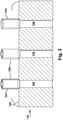
- a first coating method 200 includes providing component 100 (step 201) having aperture 109 formed in external surface 102 thereof, then additively manufacturing/printing at least one hollow member 300 (step 203) ( FIG. 3 ) on a portion of external surface 102 at aperture 109 to define a space 309 ( FIG. 4 ) above aperture 109.
- hollow member 300 is printed (step 203)
- at least one coating is applied (step 205) over external surface 102 of component 100 and around hollow member 300 to form a layer of coating 400 ( FIG. 4 ) having an applied coating thickness 403 ( FIG. 3 ).
- a portion of hollow member 300 is removed (step 207) to expose space 309 through coating 400 to aperture 109.
- portion of coating 400 can be removed with removal of a portion of hollow member 300 (step 207), thus exposing space 309 through coating 400 to aperture 109 with the reduced coating thickness 410.
- hollow member 300 includes a geometry complementary to aperture 109.
- Suitable complementary geometries for aperture 109 and hollow member 300 include, but are not limited to, tubular, semi-spherical, , square, rectangular, cylindrical, elliptical, hour-glass, chevron, any other complementary geometry capable of extending from external surface 102 at aperture 109 (e.g., in a planar or non-planar manner), or combinations thereof.
- the geometry of hollow member 300 is complementary to a diffuser-shaped cooling hole.
- Hollow member 300 is printed on external surface 102 of component 100 with any suitable height for forming a space 309 coextensive with coating 400 after step 207.
- Walls of space 309 are formed by the inner walls of hollow member 300, which are essentially collinearly equal to walls of apertures 109.
- hollow member 300 is printed on component 100 external surface 102 around an aperture 109 to extend away from external surface 102 of component 100 with a height greater than or equal to applied coating thickness 403 (see FIG. 3 or FIG. 5 ).
- Suitable coating thickness 403 heights include, but are not limited to, up to about 2.5 millimeters (0.1 inch).
- inner perimeter 310 and geometry of hollow member 300 are aligned, equal to, and complementary to an outer perimeter 111 and geometry of aperture 109.
- This configuration puts aperture 109 and hollow member 300 coaxial with each other.
- the configuration also permits a smooth linear transition from aperture 109 to hollow member 300, essentially forming a coplanar transitional inner surface from aperture 109 to hollow member 300.
- Hollow member 300 is formed by any suitable 3-D printing process, printing process, or additive manufacturing processes (hereinafter collectively “additive manufacturing processes”), such as, but not limited to, a wide variety of processes of producing a component through the successive layering of material rather than the removal of material.
- additive manufacturing processes can create complex geometries for hollow member 300 without the use of any sort of tools, molds or fixtures, and with little or no waste material. Instead of machining hollow member 300 from solid billets of material, much of which is cut away and discarded, the only material used in additive manufacturing is what is required to print hollow member 300.
- Additive manufacturing techniques typically include taking a three-dimensional computer aided design (CAD) file of the component to be formed (here hollow member 300 on a build platform formed by external surface 102 of component 100), electronically slicing the component into layers, e.g., 18-102 micrometers thick, and creating a file with a two-dimensional image of each layer, including vectors, images or coordinates.
- the file may then be loaded into a preparation software system that interprets the file such that hollow member 300 can be built by different types of additive manufacturing systems.
- 3D printing rapid prototyping (RP), and direct digital manufacturing (DDM) forms of additive manufacturing, material layers are selectively dispensed, sintered, formed, deposited, etc., to create the hollow member 300.
- powder layers are sequentially melted together to form the component. More specifically, fine powder layers are sequentially melted after being uniformly distributed using an applicator on a powder bed.
- Each applicator includes an applicator element in the form of a lip, brush, blade or roller made of metal, plastic, ceramic, carbon fibers or rubber that spreads the powder evenly over the build platform.
- the powder bed can be moved in a vertical axis. The process takes place in a processing chamber having a precisely controlled atmosphere. Once each layer is created, each two dimensional slice of the component geometry can be fused by selectively melting the powder.
- the melting may be performed by a high powered melting beam, such as but not limited to, a 100 Watt ytterbium laser, to fully weld (melt) the metal powder to form a solid.
- a high powered melting beam such as but not limited to, a 100 Watt ytterbium laser
- the melting beam moves in the X-Y direction using scanning mirrors, and has an intensity sufficient to fully weld (melt) the powder to form a solid.
- the powder bed may be lowered for each subsequent two dimensional layer, and the process repeats until the component is completely formed.
- At least one coating 400 is applied (step 205) over external surface 102 of component 100 by any suitable application method for forming coating 400 with applied coating thickness 403.
- suitable application methods include, but are not limited to: air plasma spray, high velocity oxygen fuel (HVOF) thermal spray, or electron beam physical vapor deposition or other application method now know or hereinafter developed.
- orientation and geometry of hollow member 300 with respect to the coating being applied reduces or eliminates deposition of coating 400 material in any portion of hollow member 300 (e.g., aperture 109 and space 309 (see FIG. 4 )).
- coating(s) 400 may be applied (step 205).
- upper portion 301 of hollow member 300 may be removed (Step 207).
- a portion of coating 400 can be optionally removed by any suitable removal method to provide the desired coating thickness 403, if applied coating 400 (Step 205) is too thick.
- top surface 410 ( FIG. 5 ) of coating 400 will be coplanar with the remaining portions of hollow member 300, after removal.
- Suitable removal methods include, but are not limited to: machining, sanding, grit-blasting etching, polishing, or a combination thereof.
- the coating removal includes polishing coating 400 with a diamond pad.
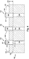
- upper portion 301 ( FIG. 4 ) of hollow member 300 includes an upper geometry that differs from a lower geometry of lower portion 303.
- hollow member 350 in Figure 4 includes a rectangular printed upper section, which is merely illustrative and not intended to limit the embodiments of the disclosure in any manner.
- This different upper geometry may be such that hollow member 300, if open at the end remote from aperture 109 (see hollow member 320 in FIG. 4 with open end 321) is configured to exclude coating 400 from entering hollow member 300.
- upper portion 301 can be closed (see hollow member 330 in Figure 4 ), or open to a degree resisting entry of coating 400, especially if coating 400 is sprayed.
- lower portion 303 geometry may conform to the geometry of aperture 109
- upper geometry 301 may confirm to the geometry of aperture 109 or include any other configuration or shape extending from lower portion 303.
- hollow member 300 at lower portion 303 may include a conforming geometry to a circular aperture 109 transitioning to an ellipsoid geometry in upper portion 301 extending away from external surface 102.
- the geometry of the space 309 includes, but is not limited to: cylindrical, spherical, square, rectangular, domed, oblong, trapezoidal, curved, straight, skewed, irregular, any other shape permitting flow therethrough, or a combination thereof.
- a further aspect of the disclosure includes printing/additively manufacturing angled hollow members 500 in conjunction with angled apertures 102 (including but not limited to those used for film cooling turbine components), as illustrated in FIGS. 6-8 .
- angled hollow members 500 in conjunction with angled apertures 102 (including but not limited to those used for film cooling turbine components), as illustrated in FIGS. 6-8 .
- Like reference characters are used for like elements.
- angled hollow members 500 are printed on a portion of external surface 102 at angled aperture 109 to define a space 509 above angled aperture 109, usually oval or ellipsoid given the intersecting aperture 109 at surface 102.
- angled hollow member 500 includes a geometry complementary to aperture 109.
- inner perimeter 510 and geometry of angled hollow member 500 can be equal to and complementary to an outer perimeter 111 and geometry of angled aperture 109 at surface 102. Accordingly, angled aperture 109 and angled hollow member 500 essentially form a coplanar transitional surface from angled aperture 109 to hollow member 500, and hollow member 500 is essentially collinear with walls of angled apertures 109.
- Hollow member 500 is printed on external surface 102 of component 100 with any suitable height for forming a space 509 with the to-be-applied coating 400.
- Walls of space 509 are formed by the inner walls of hollow member 500, with walls of space 509 essentially collinear to walls of apertures 109.
- Hollow member 500 is printed (in any suitable printing or additive manufacturing process as described above) on component 100 external surface 102 around angled aperture 109 to extend away from external surface 102 of component 100 at an angle coincident with the angle of aperture 109. This configuration puts aperture 109 and hollow member 500 coaxial with each other. As above, hollow member 500 has a height greater than or equal to the applied coating thickness 403.
- At least one coating 400 is applied over external surface 102 of component 100 by any suitable application method for forming coating 400 with applied coating thickness 403.
- the orientation and geometry of hollow member 500 being angled with respect to an applicator/sprayer of coating material reduces or eliminates coating material on or in aperture 109 and space 509.
- parts of upper and lower portions 501, 503 remain to define space 509.
- top surface of coating 410 is coplanar with the remaining portions of hollow member 500, after removal.
- removal of some portion of coating(s) 400 can occur with removal of hollow member 500.
- coating(s) 400 is applied over external surface 102 of component 100 by any suitable applicator/sprayer and application method for forming coating 400 with applied coating thickness 403.
- One suitable application method is by spraying coating(s) 400.
- a spraying coating applicator/sprayer may include a spray gun with a spray head that can be disposed at an angle with respect to apertures 109 in component 100.
- An angled spray head is effective to reduce spray entering aperture 109, as angles of aperture 109 (including those essentially orthogonal to surface 102) and of hollow members 300, 500 and may not align with the spray, thus spray should not directly enter apertures 109.
- angled spray heads can provide enhanced coverage between apertures 109 and hollow members 300, 500. With hollow members 300, 500 any spray and coating(s) 400 should be kept from entering apertures 109, which enables more efficient and effective consumption of coating without wasted spray in apertures 109 needing to be removed and scrapped.
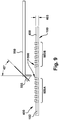
- FIG. 9 illustrates this aspect of the embodiments with spray gun 550 having an angled spray head 555.
- angled spray head 555 can be an adjustable angled spray head 555 to move its orientation to surface 102 between 0 degrees (orthogonal to surface 102) to almost 90 degrees or almost parallel to surface 102.
- angled spray head 555 can have a direct line of spray in-between printed hollow members, as shown for a set 500A of hollow members, or have an offset line of spray in-between printed hollow members, as shown for a set 500B of hollow members.
- One desirable angle is about 20 degrees from orthogonal, however that angle is not intended to limit the embodiments in any manner.
- 500 spray and coating are kept from entering apertures 109, which enables more efficient and effective consumption of coating without wasted spray in apertures 109 needing to be removed and scrapped.
- One advantage of an embodiment of the present disclosure includes maintaining original shape and dimension of apertures or cooling holes in coated components. Another advantage of an embodiment is better control of airflow for coated components. Yet another advantage is faster processing of coated components. Another advantage of an embodiment is decreased time for cleaning of cooling holes after components are coated or recoated. Yet another advantage includes significant labor savings because no drilling is required to clear cooling holes after coating.
- Components of the present disclosure can be used in any applications that undergo temperature changes, such as, but not limited to, power generation systems which include, but are not limited to: gas turbines, steam turbines, jet turbines, and other turbine assemblies.
- power generation systems which include, but are not limited to: gas turbines, steam turbines, jet turbines, and other turbine assemblies.
- embodiments of the present disclosure in comparison to coating methods not using one or more of the features disclosed herein, increase coating efficiency, provide apertures through a coating without post-coating clearing, increase control of airflow for coated components, decrease coating cost, decrease coating time, decreased time for cleaning apertures after coating components, or a combination thereof.
- Approximating language may be applied to modify any quantitative representation that could permissibly vary without resulting in a change in the basic function to which it is related. Accordingly, a value modified by a term or terms, such as “about,” “approximately” and “substantially,” are not to be limited to the precise value specified. In at least some instances, the approximating language may correspond to the precision of an instrument for measuring the value.
- range limitations may be combined and/or interchanged; such ranges are identified and include all the sub-ranges contained therein unless context or language indicates otherwise. "Approximately” as applied to a particular value of a range applies to both end values, and unless otherwise dependent on the precision of the instrument measuring the value, may indicate +/- 10% of the stated value(s).
Landscapes
- Chemical & Material Sciences (AREA)
- Engineering & Computer Science (AREA)
- Mechanical Engineering (AREA)
- Materials Engineering (AREA)
- Organic Chemistry (AREA)
- Metallurgy (AREA)
- Chemical Kinetics & Catalysis (AREA)
- Physics & Mathematics (AREA)
- Plasma & Fusion (AREA)
- General Engineering & Computer Science (AREA)
- Manufacturing & Machinery (AREA)
- Combustion & Propulsion (AREA)
- Health & Medical Sciences (AREA)
- Toxicology (AREA)
- Wood Science & Technology (AREA)
- Life Sciences & Earth Sciences (AREA)
- Ceramic Engineering (AREA)
- Turbine Rotor Nozzle Sealing (AREA)
- Powder Metallurgy (AREA)
Applications Claiming Priority (1)
| Application Number | Priority Date | Filing Date | Title |
|---|---|---|---|
| US16/849,418 US11377722B2 (en) | 2020-04-15 | 2020-04-15 | Process for coating substrates with aperture(s) |
Publications (1)
| Publication Number | Publication Date |
|---|---|
| EP3896189A1 true EP3896189A1 (de) | 2021-10-20 |
Family
ID=75302426
Family Applications (1)
| Application Number | Title | Priority Date | Filing Date |
|---|---|---|---|
| EP21166107.9A Pending EP3896189A1 (de) | 2020-04-15 | 2021-03-30 | Verfahren zur beschichtung von substraten mit öffnung(en) |
Country Status (4)
| Country | Link |
|---|---|
| US (2) | US11377722B2 (de) |
| EP (1) | EP3896189A1 (de) |
| JP (1) | JP7822701B2 (de) |
| CN (1) | CN113522700A (de) |
Cited By (1)
| Publication number | Priority date | Publication date | Assignee | Title |
|---|---|---|---|---|
| US11377722B2 (en) | 2020-04-15 | 2022-07-05 | General Electric Company | Process for coating substrates with aperture(s) |
Citations (4)
| Publication number | Priority date | Publication date | Assignee | Title |
|---|---|---|---|---|
| WO2014160695A1 (en) * | 2013-03-28 | 2014-10-02 | United Technologies Corporation | Gas turbine component manufacturing |
| EP2881489A1 (de) * | 2013-12-05 | 2015-06-10 | General Electric Company | Beschichtungsverfahren und Schablone zur Verwendung mit den Beschichtungsverfahren |
| US20150159254A1 (en) * | 2013-12-06 | 2015-06-11 | General Electric Company | Coating methods and a coated substrate |
| US20160089692A1 (en) * | 2014-09-30 | 2016-03-31 | General Electric Company | Turbine component coating processes and turbine components |
Family Cites Families (6)
| Publication number | Priority date | Publication date | Assignee | Title |
|---|---|---|---|---|
| US6329015B1 (en) * | 2000-05-23 | 2001-12-11 | General Electric Company | Method for forming shaped holes |
| US20140035995A1 (en) * | 2010-12-07 | 2014-02-06 | Sun Chemical Corporation | Aerosol jet printable metal conductive inks, glass coated metal conductive inks and uv-curable dielectric inks and methods of preparing and printing the same |
| JP5923936B2 (ja) * | 2011-11-09 | 2016-05-25 | 株式会社Ihi | フィルム冷却構造及びタービン翼 |
| GB201205020D0 (en) | 2012-03-22 | 2012-05-09 | Rolls Royce Plc | A method of manufacturing a thermal barrier coated article |
| US9151175B2 (en) * | 2014-02-25 | 2015-10-06 | Siemens Aktiengesellschaft | Turbine abradable layer with progressive wear zone multi level ridge arrays |
| US11377722B2 (en) | 2020-04-15 | 2022-07-05 | General Electric Company | Process for coating substrates with aperture(s) |
-
2020
- 2020-04-15 US US16/849,418 patent/US11377722B2/en active Active
-
2021
- 2021-03-12 CN CN202110272298.1A patent/CN113522700A/zh active Pending
- 2021-03-16 JP JP2021042962A patent/JP7822701B2/ja active Active
- 2021-03-30 EP EP21166107.9A patent/EP3896189A1/de active Pending
-
2022
- 2022-03-22 US US17/655,892 patent/US20220213583A1/en not_active Abandoned
Patent Citations (4)
| Publication number | Priority date | Publication date | Assignee | Title |
|---|---|---|---|---|
| WO2014160695A1 (en) * | 2013-03-28 | 2014-10-02 | United Technologies Corporation | Gas turbine component manufacturing |
| EP2881489A1 (de) * | 2013-12-05 | 2015-06-10 | General Electric Company | Beschichtungsverfahren und Schablone zur Verwendung mit den Beschichtungsverfahren |
| US20150159254A1 (en) * | 2013-12-06 | 2015-06-11 | General Electric Company | Coating methods and a coated substrate |
| US20160089692A1 (en) * | 2014-09-30 | 2016-03-31 | General Electric Company | Turbine component coating processes and turbine components |
Cited By (1)
| Publication number | Priority date | Publication date | Assignee | Title |
|---|---|---|---|---|
| US11377722B2 (en) | 2020-04-15 | 2022-07-05 | General Electric Company | Process for coating substrates with aperture(s) |
Also Published As
| Publication number | Publication date |
|---|---|
| JP2022044540A (ja) | 2022-03-17 |
| US11377722B2 (en) | 2022-07-05 |
| US20220213583A1 (en) | 2022-07-07 |
| JP7822701B2 (ja) | 2026-03-03 |
| US20210324507A1 (en) | 2021-10-21 |
| CN113522700A (zh) | 2021-10-22 |
Similar Documents
| Publication | Publication Date | Title |
|---|---|---|
| CN101235499B (zh) | 采用适应性加工路径沉积方法进行的激光净成形生产 | |
| EP3415718B1 (de) | Gasturbinenmotorkomponenten mit luftkühlungsmerkmalen und zugehörige verfahren zur herstellung davon | |
| US6329015B1 (en) | Method for forming shaped holes | |
| EP2559856B1 (de) | Herstellungsverfahren für komponente mit kühlungskanälen | |
| EP1610923B1 (de) | Laserpulverschmelzerparatur von z-kerben mit inconel 713-pulver | |
| EP0807744B1 (de) | Fluidum gekühlter Gegenstand und seine Herstellungsweise | |
| CN102528413B (zh) | 修改基底以在其中形成通路孔的方法和相关制品 | |
| EP2301730A1 (de) | Lochbohrung in der Nähe einer Rückwand | |
| US20120295061A1 (en) | Components with precision surface channels and hybrid machining method | |
| EP3844370B1 (de) | Additivträger mit integrierter filmkühlung | |
| CN102691533A (zh) | 带有形成在涂层中的冷却通道的构件和制造方法 | |
| EP3475026A1 (de) | Verfahren zur reparatur von folienlöchern in einer oberfläche | |
| JP2014087924A (ja) | マイクロ冷却される皮膜層を備えた構成要素及び製造方法 | |
| US12558726B2 (en) | Additively manufactured object using mask over opening for coating | |
| US20220213583A1 (en) | Process for coating substrates with aperture(s) | |
| EP3475533A1 (de) | Verfahren zur reparatur einer beschädigten komponente eines motors | |
| JP6254820B2 (ja) | マイクロ冷却パターン形成被膜層を持つコンポーネント及び製造方法 | |
| US10995620B2 (en) | Turbomachine component with coating-capturing feature for thermal insulation | |
| EP3907025B1 (de) | Anformbare beschichtungsmaske für ein bauteil und system |
Legal Events
| Date | Code | Title | Description |
|---|---|---|---|
| PUAI | Public reference made under article 153(3) epc to a published international application that has entered the european phase |
Free format text: ORIGINAL CODE: 0009012 |
|
| STAA | Information on the status of an ep patent application or granted ep patent |
Free format text: STATUS: THE APPLICATION HAS BEEN PUBLISHED |
|
| AK | Designated contracting states |
Kind code of ref document: A1 Designated state(s): AL AT BE BG CH CY CZ DE DK EE ES FI FR GB GR HR HU IE IS IT LI LT LU LV MC MK MT NL NO PL PT RO RS SE SI SK SM TR |
|
| B565 | Issuance of search results under rule 164(2) epc |
Effective date: 20210526 |
|
| STAA | Information on the status of an ep patent application or granted ep patent |
Free format text: STATUS: REQUEST FOR EXAMINATION WAS MADE |
|
| 17P | Request for examination filed |
Effective date: 20220121 |
|
| RBV | Designated contracting states (corrected) |
Designated state(s): AL AT BE BG CH CY CZ DE DK EE ES FI FR GB GR HR HU IE IS IT LI LT LU LV MC MK MT NL NO PL PT RO RS SE SI SK SM TR |
|
| RAP1 | Party data changed (applicant data changed or rights of an application transferred) |
Owner name: GENERAL ELECTRIC TECHNOLOGY GMBH |
|
| RAP3 | Party data changed (applicant data changed or rights of an application transferred) |
Owner name: GE VERNOVA TECHNOLOGY GMBH |