EP3896207A1 - Aiguilleteuse - Google Patents
Aiguilleteuse Download PDFInfo
- Publication number
- EP3896207A1 EP3896207A1 EP20193058.3A EP20193058A EP3896207A1 EP 3896207 A1 EP3896207 A1 EP 3896207A1 EP 20193058 A EP20193058 A EP 20193058A EP 3896207 A1 EP3896207 A1 EP 3896207A1
- Authority
- EP
- European Patent Office
- Prior art keywords
- needle
- guide means
- wires
- needling
- needles
- Prior art date
- Legal status (The legal status is an assumption and is not a legal conclusion. Google has not performed a legal analysis and makes no representation as to the accuracy of the status listed.)
- Granted
Links
Images



Classifications
-
- D—TEXTILES; PAPER
- D04—BRAIDING; LACE-MAKING; KNITTING; TRIMMINGS; NON-WOVEN FABRICS
- D04H—MAKING TEXTILE FABRICS, e.g. FROM FIBRES OR FILAMENTARY MATERIAL; FABRICS MADE BY SUCH PROCESSES OR APPARATUS, e.g. FELTS, NON-WOVEN FABRICS; COTTON-WOOL; WADDING ; NON-WOVEN FABRICS FROM STAPLE FIBRES, FILAMENTS OR YARNS, BONDED WITH AT LEAST ONE WEB-LIKE MATERIAL DURING THEIR CONSOLIDATION
- D04H18/00—Needling machines
- D04H18/02—Needling machines with needles
Definitions
- the present invention relates to a needling machine for needling a textile fabric, such as a nonwoven fabric, woven fabric or scrim.
- Needle machines are well known and for example in Lünenment and Albrecht: “ Nonwovens “, Georg-Thieme-Verlag Stuttgart, 1982, pp. 122 to 129 or in Albrecht, Fuchs, Kittelmann: “Vliesstoffe”, Wiley-VCH Verlag Weinheim, 2000, p. 270 ff . described.
- the present invention is based on the object of specifying a needling machine with which a flat textile structure can be needled in a particularly uniform manner.
- the needle machine according to the invention for needling a textile fabric comprises at least one needle bar arranged in a needling zone on which at least one needle board is arranged, a plurality of needles protruding from the at least one needle board.
- the needle machine comprises at least one drive device for the at least one needle bar, which is designed to move the at least one needle bar in at least a reciprocating stroke movement.
- the needling machine also comprises upper and lower support and guide means for the textile fabric, which extend at least in the area of the needling zone, with an intermediate space for the passage of the textile fabric being formed between the upper support and guide means and the lower support and guide means .
- the upper support and guide means are each formed by a plurality of tensioned wires arranged in parallel, between which upper passage openings for the needles of the at least one needle board are arranged, and the lower support and guide means are each formed by a plurality of tensioned wires arranged in parallel , between which lower passage openings for the needles of the at least one needle board are arranged.
- the wires of the upper and lower support and guide means are mounted in such a way that they are immovable in a conveying direction of the needle loom.
- Such a needling machine is particularly suitable for ensuring a high penetration density of the needles into the textile fabric and for bringing about a particularly uniform needling of the textile fabric.
- the wires of the upper and lower support and guide means are preferably fixed in the needle loom.
- the wires do not move and the textile fabric slides along the upper and lower support and guide means formed by the wires through the needling zone.
- the needling machine is designed in such a way that it moves the textile fabric in the conveying direction at least through the needling zone.
- the conveying direction of the needling machine corresponds to the conveying direction of the textile fabric, at least in the needling zone.
- the wires of the upper and lower support and guide means are arranged in a stationary manner, at least in the conveying direction.
- the wires can be arranged completely stationary.
- the wires of the upper and lower support and guide means can, however, also be mounted so as to be movable relative to one another in a direction perpendicular to the conveying direction of the needle loom towards one another or away from one another. As a result, the space can be adapted to different thicknesses of the textile fabric.
- the needling machine In order to move the textile fabric in the conveying direction through the needling zone, the needling machine generally in every embodiment preferably comprises a conveying device for the textile fabric.
- the conveying device can comprise conveying means which are arranged upstream of the needling zone in the conveying direction and are set up to feed the textile fabric to the needling zone.
- These conveying means arranged upstream of the needling zone comprise, for example, a conveyor belt and / or conveyor rollers.
- the conveying device can additionally or alternatively comprise conveying means which are arranged downstream of the needling zone and are set up to convey the textile fabric or a solidified textile fabric pick up after the needling zone and move forward.
- These conveying means arranged downstream of the needling zone comprise, for example, a conveyor belt and / or conveyor rollers.
- a simple construction of the needling machine is promoted by the fact that the needling machine itself does not have any conveying means for the textile fabric in the needling zone.
- the number of juxtaposed wires of the upper support and guiding means is at least 250 per meter of working width across the conveying direction, preferably at least 400 per meter of working width, more preferably at least 500 per meter of working width
- the number of juxtaposed wires of the lower Support and guide means is at least 250 per meter of working width transversely to the conveying direction, preferably at least 400 per meter of working width, more preferably at least 500 per meter of working width.
- the wires of the upper support and guide means and the wires of the lower support and guide means are preferably finite in all embodiments and each have a first free end and a second free end.
- the first free end of each wire is preferably defined in the conveying direction upstream of the needling zone in the needle machine and the second free end of each wire is defined in the conveying direction downstream of the needling zone in the needle machine.
- wires of the upper support and guide means and the wires of the lower support and guide means run parallel to one another. In this way, the guidance of the textile fabric in the needling zone is optimized.
- Each wire preferably runs in the conveying direction F of the textile fabric.
- a longitudinal direction of each wire is then aligned parallel to the conveying direction of the textile fabric.
- the wires are thus immovably mounted in the needle machine in the conveying direction and in their longitudinal direction.
- the wires can also run obliquely to the conveying direction of the textile fabric.
- a longitudinal direction of each wire is then oriented obliquely to the conveying direction of the textile fabric.
- the longitudinal direction of each wire then has a component parallel to the conveying direction and a component perpendicular to the conveying direction. Consequently, in this case too, the wires are stored in the needle loom in such a way that they are immovable in the conveying direction and preferably also perpendicular to the conveying direction.
- the wires of the upper support and guide means and the wires of the lower support and guide means are aligned with one another in the vertical direction. This ensures that none of the needles collide with the wires of the upper support and guide means and the lower support and guide means during the puncturing process.
- the needle machine preferably comprises at least one hold-down plate and at least one throat plate, which are arranged in the needling zone.
- the hold-down plate and the throat plate then consist of the upper support and guide means or the lower support and guide means.
- the upper support and guide means with respect to the needle bar form a hold-down plate for holding down the textile fabric when the needles of the needle bar are pulled out of the textile fabric
- the lower support and guide means form a needle plate with respect to the needle bar to support and hold back the textile Flat structure when the needles of the needle bar penetrate the textile fabric and penetrate it.
- the upper supporting and guiding means can also form a throat plate and the lower supporting and guiding means can form a hold-down plate when the needle bar is arranged below the textile fabric. It is also possible in a double needle machine with an upper needle board and a lower needle board both the upper support and guide means and the lower support and guide means both a hold-down plate for the needles of one needle board and a throat plate for the needles of each other needle board.
- all stitch and hold-down plates of the needle machine are preferably exclusive in all embodiments formed by the wires of the upper and lower support and guide means. Further stitch or hold-down plates are not provided.
- the upper passage openings between the wires of the upper support and guide means have a width between 0.5 mm and 10 mm, preferably between 0.7 mm and 8 mm, more preferably between 0.8 mm and 5 mm.
- the lower passage openings between the wires of the lower support and guide means have a width of between 0.5 mm and 10 mm, preferably between 0.7 mm and 8 mm, more preferably between 0.8 mm and 5 mm.
- the wires of the upper support and guide means have a diameter of between 0.4 mm and 2 mm, preferably between 0.5 mm and 1.5 mm, more preferably between 0.6 mm and 1.2 mm .
- the wires of the lower support and guide means have a diameter of between 0.4 mm and 2 mm, preferably between 0.5 mm and 1.5 mm, more preferably between 0.6 mm and 1 mm , 2 mm.
- the small diameter of the wires promotes a particularly tight stitch pattern and a particularly even, solidified end product.
- the needles are arranged in rows which run parallel to an extension direction of the wires of the upper support and guide means and which are arranged at a distance from one another which corresponds to a distance between the wires of the upper support and guide means.
- the needle loom also has a cleaning device for each wire. This is particularly suitable for removing fibers adhering to the wire, which are pulled from the textile fabric during the needling process, and thus ensuring that the needling process runs smoothly.
- the cleaning device has a nose which runs obliquely in the direction of the respective wire on one side of the respective wire which faces away from the intermediate space formed between the upper and lower support and guide means and makes contact with the respective wire.
- the needle loom also has a tensioning device for each wire.
- the first and / or the second end of each wire is attached to a tensioning element.
- the tensioning element for example a bolt or pin, can be rotatably mounted and the first or the second end of a wire is wound around the tensioning element so that the wire can be tensioned by rotating the tensioning element. A readjustment of the wire tension and an exchange of wires can thus be carried out in a simple manner in the manner of piano strings.
- a deflection device for each wire is also arranged between the tensioning device and the needling zone, by means of which the respective wire is rotated through an angle of between 60 ° and 120 °, preferably between 70 ° and 110 °, more preferably between 80 ° and 100 ° , is deflected based on its arrangement in the needling zone.
- the wires are deflected upwards or downwards in an area outside the needling zone and release the textile fabric unhindered.
- the needles in each needle board are more preferably at a density of at least 500 needles / dm 2 , preferably at least 1,000 needles / dm 2 at least 1,500 needles / dm 2 arranged.
- Such high needle densities lead to a particularly uniform stitch pattern in the solidified end product.
- the needles are arranged in needle modules, each needle module having a plurality of needles, and the needle modules being received in recesses or carriers of the at least one needle board and fastened there.
- the arrangement of the needles in needle modules has several advantages. In this way, individual needle modules can be exchanged if there are defective needles and the entire needle board does not have to be removed to retrofit new needles.
- the needle modules can also be arranged displaceably in the needle board and thus the stitch pattern and the needle board assembly can be designed variably.
- the needle modules can be arranged so close to one another that no space remains between individual needle modules.
- the wires are preferably designed as metal wires, in particular steel wires, which are preferably rustproof.
- the needling zone extends in the conveying direction F preferably over a range from 20 cm to 200 cm, more preferably 25 cm to 80 cm.
- the needling zone extends transversely to the conveying direction F, preferably over a range from 200 cm to 500 cm, more preferably 250 cm to 400 cm.
- Each needle module can have a single longitudinal row of needles or multiple longitudinal rows of needles.
- FIG. 1 the schematic structure of a needle loom 1 is shown in a side view.
- a textile fabric 2, such as a nonwoven web is fed to an inlet of the needle machine 1 and conveyed to a needling zone V.
- a needle bar 4 is arranged with a needle board 6 attached to it, which is equipped with needles 8 for solidifying the sheet-like structure 2.
- the textile fabric 2 to be needled is guided in an intermediate space 7 between upper support and guide means 10 for holding down the textile fabric 2 and lower support and guide means 12 for supporting the textile fabric 2 in the needling zone V.
- the needles 8 compact the flat structure 2 in that they are pierced at high frequency into the textile flat structure 2 and pulled out again.
- the needles 8 pass through upper and lower passage openings 30, 32 in the upper support and guide means 10 and the lower support and guide means 12, see Figure 6a . While in Fig. 1 the upper and lower support and guide means 10, 12 are only sketched schematically, is the actual design of the upper and lower support and guide means 10, 12 according to the present invention shown in more detail in the following figures.
- a drive device 14 is provided, which is designed, for example, as a connecting rod drive.
- the needle board 6 with the needles 8 can have a parallel horizontal stroke H in a preferred embodiment of a needle machine 1 to conveying direction F.
- the needle board 6 with the needles 8 can be moved in the conveying direction F together with the textile fabric 2.
- the needles 8 are moved along with the fabric 2 in order to minimize a relative movement between the needles 8 and the fabric 2.
- either an auxiliary drive engaging the needle board 6 can be provided, or the drive device 14 can be designed accordingly or coupled in a certain way to the needle bar 4, as is known to the person skilled in the art.
- the resulting product is a solidified textile fabric 16, for example a fleece.
- needle machines 1 A wide variety of different types of needle machines 1 are known to those skilled in the art, including double needle machines in which needling is carried out from above and below by means of two needle bars 4, needle machines with one or more needle boards 6 per needle bar, or needle machines with and without a horizontal stroke. It goes without saying that the present invention can be applied to different forms of needling machines and is not restricted to the embodiment of a needling machine 1 described herein.
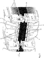
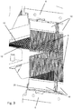
- FIGs. 2 to 4 an exemplary embodiment of the needle loom according to the invention is shown in greater detail.
- the needle machine shown is a double needle machine with an upper needle board 6 and a lower needle board 6.
- the lower support and guide means 12 also have a hold-down function for the needles 8 of the needle board 6 arranged below the sheet 2 the time offset of the puncture movements is not.
- the needles 8 on both needle boards 6 are arranged mirror-symmetrically to the longitudinal center plane lying between the needle boards 6, but they can also be arranged offset from one another.
- a puncture position of the needles 8 of the upper needle board 6 is shown, in which these needles 8 pass through the passage openings 30, 32 in the upper support and guide means 10 and in the lower support and guide means 12.
- the lower needles 8 would correspondingly have passed through the passage openings 30, 32.
- the needles 8 in Figs. 2 to 4 are shown with blunt tips for reasons of clarity. In reality, the tips of the needles 8 are pointed.
- the needles 8 are each received in needle modules 18, which in turn are received in receptacles or carriers 20 of the needle board 6.
- C-shaped carriers 20 are provided for receiving a thicker section of the needle module 18.
- the carrier 20 has at its open end two shoulders which extend inwardly towards one another.
- the needle modules 18 can be arranged in rows and columns in the needle board 6, as shown in FIG Fig. 2 emerges.
- the needle modules can be arranged in almost any way as long as the respective needles 8 always hit through openings 30, 32 of the support and guide means 10, 12 during the puncturing movement. In this way, rows of needles with several dozen or several hundred needles 8 can be formed in the conveying direction F of the textile fabric 2.
- Each needle bar 4 can have exactly one needle board 6 or also have two or more needle boards 6.
- Several needling machines can also be arranged one after the other in the conveying direction F.
- the upper support and guide means 10 and the lower support and guide means 12 are each formed according to the invention by parallel, tensioned wires 22.
- the wires 22 preferably run in the conveying direction F of the textile fabric 2.
- the arrangement of the wires 22 in the upper support and guide means 10 and in the lower support and guide means 12 preferably corresponds to one another, so that the passage openings 30 with regard to their arrangement with the passage openings 32 correspond.
- the passage openings 30, 32 between the wires 22 of the upper and lower support and guide means 10, 12 have a width B of between 0.5 mm and 10 mm.
- the wires 22 of the upper and lower support and guide means 10, 12 have a diameter D of between 0.4 mm and 2 mm.
- a needle 8 corresponding to a passage opening 30, 32 is arranged transversely to the conveying direction F.
- two or more needles 8 pass through one of the passage openings 30, 32 next to one another transversely to the conveying direction F.
- the wires 22 at the front or rear end of the needle bar 4 are each bent upwards or downwards and are tensioned there by means of suitable tensioning devices 24 (only shown schematically here) for each wire 22.
- suitable tensioning devices 24 only shown schematically here
- the wire route is symmetrical to this.
- a deflection device 26 is provided between the tensioning device 24 and the needling zone V, by means of which the respective wire 22 is deflected by an angle of between 60 ° and 120 °, based on its arrangement in the needling zone V.
- the angle is preferably 90 °. This results in a U-shape for the path of the wires 22.
- the needling machine further comprises a cleaning device 28 for each wire 22, which is preferably arranged downstream of the needling zone V.
- a cleaning device 28 for each wire 22, which is preferably arranged downstream of the needling zone V.
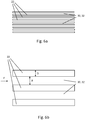
- FIG Figures 5a and 5b shown A possible embodiment of this cleaning device 28 is shown in FIG Figures 5a and 5b shown.
- the cleaning device 28 is formed by a nose 29 which runs obliquely from above or from below in the direction of the respective wire 22 and obliquely counter to the conveying direction F and which touches the wire 22. It is preferred that each nose 29 has a groove at its tip in which the wire 28 is at least partially received. This also ensures good guidance of the wires 22. With such an arrangement, fibers moved along a wire 22 can be diverted upward from the nose 29 into a recess, thereby preventing clogging in the exit area of the support and guide means 10, 12.
- the cleaning device 28 may include further components which ensure that the fibers diverted into the recesses are permanently removed from there. Brushes or blowers, for example, can be used for this purpose.
- the cleaning device 28 can also be connected in one piece with the deflection device 26 or with a section of the deflection device 26.
Landscapes
- Engineering & Computer Science (AREA)
- Textile Engineering (AREA)
- Nonwoven Fabrics (AREA)
- Catching Or Destruction (AREA)
- Infusion, Injection, And Reservoir Apparatuses (AREA)
- External Artificial Organs (AREA)
Priority Applications (2)
| Application Number | Priority Date | Filing Date | Title |
|---|---|---|---|
| US17/209,963 US11384460B2 (en) | 2020-04-17 | 2021-03-23 | Needlepunching machine |
| CN202110400362.XA CN113529284B (zh) | 2020-04-17 | 2021-04-14 | 针刺机 |
Applications Claiming Priority (1)
| Application Number | Priority Date | Filing Date | Title |
|---|---|---|---|
| EP20170250.3A EP3896206B1 (fr) | 2020-04-17 | 2020-04-17 | Aiguilleteuse |
Publications (2)
| Publication Number | Publication Date |
|---|---|
| EP3896207A1 true EP3896207A1 (fr) | 2021-10-20 |
| EP3896207B1 EP3896207B1 (fr) | 2022-04-13 |
Family
ID=70333813
Family Applications (2)
| Application Number | Title | Priority Date | Filing Date |
|---|---|---|---|
| EP20170250.3A Active EP3896206B1 (fr) | 2020-04-17 | 2020-04-17 | Aiguilleteuse |
| EP20193058.3A Active EP3896207B1 (fr) | 2020-04-17 | 2020-08-27 | Aiguilleteuse |
Family Applications Before (1)
| Application Number | Title | Priority Date | Filing Date |
|---|---|---|---|
| EP20170250.3A Active EP3896206B1 (fr) | 2020-04-17 | 2020-04-17 | Aiguilleteuse |
Country Status (5)
| Country | Link |
|---|---|
| US (1) | US11384460B2 (fr) |
| EP (2) | EP3896206B1 (fr) |
| CN (1) | CN113529284B (fr) |
| ES (1) | ES2936633T3 (fr) |
| PL (1) | PL3896206T3 (fr) |
Cited By (3)
| Publication number | Priority date | Publication date | Assignee | Title |
|---|---|---|---|---|
| EP4202099A1 (fr) * | 2021-12-22 | 2023-06-28 | Oskar Dilo Maschinenfabrik KG | Planche à aiguilles et procédé de montage d'une planche a aiguilles |
| CN117867763A (zh) * | 2023-12-21 | 2024-04-12 | 浙江星辉新材料科技有限公司 | 一种针刺板的夹紧装置 |
| EP4382652A1 (fr) * | 2022-12-08 | 2024-06-12 | Oskar Dilo Maschinenfabrik KG | Machine à aiguilles et procédé d'implantation et de fonctionnement d'une telle machine |
Citations (2)
| Publication number | Priority date | Publication date | Assignee | Title |
|---|---|---|---|---|
| DE3304392A1 (de) * | 1983-02-09 | 1984-08-09 | Peter Dipl.-Ing. 7120 Bietigheim-Bissingen Stärk | Vorrichtung zum herstellen eines textilen stoffes aus einem faservlies |
| EP3165660A1 (fr) * | 2015-11-06 | 2017-05-10 | Oskar Dilo Maschinenfabrik KG | Planche a aiguilles |
Family Cites Families (16)
| Publication number | Priority date | Publication date | Assignee | Title |
|---|---|---|---|---|
| US2974393A (en) * | 1959-01-08 | 1961-03-14 | Du Pont | Apparatus for needle punching sheet materials |
| US3538564A (en) * | 1968-04-12 | 1970-11-10 | Union Carbide Corp | Method of making a nonwoven fabric |
| US3488819A (en) * | 1968-05-17 | 1970-01-13 | Monsanto Co | Method and apparatus for making dimensionally stable nonwoven fabric |
| US3621540A (en) * | 1969-11-03 | 1971-11-23 | Crompton & Knowles Corp | Fibrous batt feeding mechanism |
| US3845529A (en) * | 1972-08-31 | 1974-11-05 | Riegel Textile Corp | Apparatus and process for tacking fabrics |
| FR2678547B1 (fr) * | 1991-07-03 | 1995-03-10 | Guy Leroy | Procede et dispositif pour la realisation de nappes composites et composites obtenus. |
| FR2729403B1 (fr) * | 1995-01-12 | 1997-05-09 | Asselin | Convoyeur a brosses et aiguilleteuse equipee de ce convoyeur |
| DE19730532A1 (de) | 1997-07-16 | 1999-01-21 | Dilo Kg Maschf Oskar | Nadelmaschine |
| TW508390B (en) * | 2001-05-09 | 2002-11-01 | Ind Tech Res Inst | Feeding device for preneedling nonwoven fabrics |
| US6374469B1 (en) * | 2001-06-13 | 2002-04-23 | Messier-Bugatti | Needling machine provided with a device for measuring penetration |
| KR101231014B1 (ko) * | 2002-12-03 | 2013-02-07 | 벨크로 인더스트리스 비.브이. | 캐리어 시트를 통한 루프 형성 니들링 |
| AT414331B (de) * | 2003-07-15 | 2008-01-15 | Fehrer Textilmasch | Vorrichtung zum nadeln eines vlieses |
| US7562426B2 (en) * | 2005-04-08 | 2009-07-21 | Velcro Industries B.V. | Needling loops into carrier sheets |
| CN202298099U (zh) * | 2011-10-11 | 2012-07-04 | 东华大学 | 一种非织造栅控恒压电晕充电针刺加固机构 |
| EP2886694B1 (fr) * | 2013-12-17 | 2016-09-07 | Oskar Dilo Maschinenfabrik KG | Procédé d'entraînement d'une planche à aiguilles dans une aiguilleteuse |
| CN110295458B (zh) * | 2019-07-31 | 2024-08-02 | 上海应用技术大学 | 一种非织造布用单主轴双驱动针板的针刺机 |
-
2020
- 2020-04-17 PL PL20170250.3T patent/PL3896206T3/pl unknown
- 2020-04-17 EP EP20170250.3A patent/EP3896206B1/fr active Active
- 2020-04-17 ES ES20170250T patent/ES2936633T3/es active Active
- 2020-08-27 EP EP20193058.3A patent/EP3896207B1/fr active Active
-
2021
- 2021-03-23 US US17/209,963 patent/US11384460B2/en active Active
- 2021-04-14 CN CN202110400362.XA patent/CN113529284B/zh active Active
Patent Citations (2)
| Publication number | Priority date | Publication date | Assignee | Title |
|---|---|---|---|---|
| DE3304392A1 (de) * | 1983-02-09 | 1984-08-09 | Peter Dipl.-Ing. 7120 Bietigheim-Bissingen Stärk | Vorrichtung zum herstellen eines textilen stoffes aus einem faservlies |
| EP3165660A1 (fr) * | 2015-11-06 | 2017-05-10 | Oskar Dilo Maschinenfabrik KG | Planche a aiguilles |
Non-Patent Citations (1)
| Title |
|---|
| ALBRECHTFUCHSKITTELMANN: "Vliesstoffe", 2000, GEORG-THIEME-VERLAG, pages: 270 - 129 |
Cited By (5)
| Publication number | Priority date | Publication date | Assignee | Title |
|---|---|---|---|---|
| EP4202099A1 (fr) * | 2021-12-22 | 2023-06-28 | Oskar Dilo Maschinenfabrik KG | Planche à aiguilles et procédé de montage d'une planche a aiguilles |
| US12049717B2 (en) | 2021-12-22 | 2024-07-30 | Oskar Dilo Masc hinenfabrik KG | Needle board and method for populating a needle board |
| EP4382652A1 (fr) * | 2022-12-08 | 2024-06-12 | Oskar Dilo Maschinenfabrik KG | Machine à aiguilles et procédé d'implantation et de fonctionnement d'une telle machine |
| US12276055B2 (en) | 2022-12-08 | 2025-04-15 | Oskar Dilo Maschinenfabrik Kg | Needle machine and method for equipping and operating a needle machine |
| CN117867763A (zh) * | 2023-12-21 | 2024-04-12 | 浙江星辉新材料科技有限公司 | 一种针刺板的夹紧装置 |
Also Published As
| Publication number | Publication date |
|---|---|
| EP3896207B1 (fr) | 2022-04-13 |
| CN113529284B (zh) | 2022-12-27 |
| ES2936633T3 (es) | 2023-03-21 |
| EP3896206A1 (fr) | 2021-10-20 |
| PL3896206T3 (pl) | 2023-04-11 |
| US20210324558A1 (en) | 2021-10-21 |
| EP3896206B1 (fr) | 2022-12-14 |
| US11384460B2 (en) | 2022-07-12 |
| CN113529284A (zh) | 2021-10-22 |
Similar Documents
| Publication | Publication Date | Title |
|---|---|---|
| EP0082538B1 (fr) | Métier à tricoter pour la fabrication de peluche à poil coupé | |
| DE2525542A1 (de) | Tufting-maschine | |
| EP3896207B1 (fr) | Aiguilleteuse | |
| CH690182A5 (de) | Verfahren und Kettenwirkmaschine zur Herstellung einer gemusterten Wirkware. | |
| DE3140480A1 (de) | "kettenwirkmaschine mit einem schussfadenmagazin und einer vlies-zufuehrvorrichtung" | |
| DE1435767B1 (de) | Genadelte textilware aus einem vlies von lose geschich teten fasern und verfahren zur herstellung derselben | |
| EP0293956B1 (fr) | Procédé et dispositif pour traiter les fils de tricotage au bord du tricot | |
| EP0582214B1 (fr) | Dispositif pour la fabrication d'articles implantés de touffes par piquage | |
| DE2924517A1 (de) | Vorrichtung zur bildung von kurzen schlaufen in einer tufting-maschine | |
| EP3744889B1 (fr) | Plaque de maintien en place et plaque de piquage pour une machine à aiguilles | |
| EP2886694B1 (fr) | Procédé d'entraînement d'une planche à aiguilles dans une aiguilleteuse | |
| DE2928094A1 (de) | Jacquardeinrichtung fuer kettenwirkmaschinen | |
| DE2157947A1 (de) | Vorrichtung zum herstellen eines stichverstaerkten oder gekettelten stoffes | |
| DE3003570C2 (fr) | ||
| DE1952558A1 (de) | Textilverbundstoff,insbesondere Vliesstoff sowie Vorrichtung und Verfahren zu seiner Herstellung | |
| EP0179072B1 (fr) | Procede de fabrication d'un tissu a motifs tricote en chaine et metier chaine pour sa mise en o euvre | |
| DD209362A3 (de) | Kettenwirkmaschine, insbesondere naehwirkmaschine | |
| DE3119636A1 (de) | Vorrichtung zum oeffnen von polschlingen an vielnadelmaschinen, insbesondere naehwirkmaschinen | |
| CH650038A5 (de) | Mascheneinstreicher fuer eine strickmaschine. | |
| DE4240134C2 (de) | Vorrichtung zur Herstellung von Tuftingware | |
| DE1685144C3 (de) | Schiffchenstickmaschine mit einer Einrichtung zum Faden- oder Farbwechsel bzw. Rapportwechsel | |
| CH666294A5 (de) | Strickmaschine. | |
| DE1435767C (de) | Genadelte Textilware aus einem Vlies von lose geschichteten Fasern und Verfahren zur Herstellung derselben | |
| DE1635814C3 (de) | Kettenwirkmaschine zur Herstellung von Kettenwirkware mit abstehenden Schlingen | |
| CH661301A5 (de) | Kettenwirkmaschine. |
Legal Events
| Date | Code | Title | Description |
|---|---|---|---|
| PUAI | Public reference made under article 153(3) epc to a published international application that has entered the european phase |
Free format text: ORIGINAL CODE: 0009012 |
|
| STAA | Information on the status of an ep patent application or granted ep patent |
Free format text: STATUS: THE APPLICATION HAS BEEN PUBLISHED |
|
| AK | Designated contracting states |
Kind code of ref document: A1 Designated state(s): AL AT BE BG CH CY CZ DE DK EE ES FI FR GB GR HR HU IE IS IT LI LT LU LV MC MK MT NL NO PL PT RO RS SE SI SK SM TR |
|
| B565 | Issuance of search results under rule 164(2) epc |
Effective date: 20201007 |
|
| STAA | Information on the status of an ep patent application or granted ep patent |
Free format text: STATUS: REQUEST FOR EXAMINATION WAS MADE |
|
| 17P | Request for examination filed |
Effective date: 20211103 |
|
| RBV | Designated contracting states (corrected) |
Designated state(s): AL AT BE BG CH CY CZ DE DK EE ES FI FR GB GR HR HU IE IS IT LI LT LU LV MC MK MT NL NO PL PT RO RS SE SI SK SM TR |
|
| GRAP | Despatch of communication of intention to grant a patent |
Free format text: ORIGINAL CODE: EPIDOSNIGR1 |
|
| STAA | Information on the status of an ep patent application or granted ep patent |
Free format text: STATUS: GRANT OF PATENT IS INTENDED |
|
| RIC1 | Information provided on ipc code assigned before grant |
Ipc: D04H 18/02 20120101AFI20211123BHEP |
|
| INTG | Intention to grant announced |
Effective date: 20211223 |
|
| GRAS | Grant fee paid |
Free format text: ORIGINAL CODE: EPIDOSNIGR3 |
|
| GRAA | (expected) grant |
Free format text: ORIGINAL CODE: 0009210 |
|
| STAA | Information on the status of an ep patent application or granted ep patent |
Free format text: STATUS: THE PATENT HAS BEEN GRANTED |
|
| AK | Designated contracting states |
Kind code of ref document: B1 Designated state(s): AL AT BE BG CH CY CZ DE DK EE ES FI FR GB GR HR HU IE IS IT LI LT LU LV MC MK MT NL NO PL PT RO RS SE SI SK SM TR |
|
| REG | Reference to a national code |
Ref country code: GB Ref legal event code: FG4D Free format text: NOT ENGLISH |
|
| REG | Reference to a national code |
Ref country code: CH Ref legal event code: EP |
|
| REG | Reference to a national code |
Ref country code: DE Ref legal event code: R096 Ref document number: 502020000927 Country of ref document: DE |
|
| REG | Reference to a national code |
Ref country code: IE Ref legal event code: FG4D Free format text: LANGUAGE OF EP DOCUMENT: GERMAN |
|
| REG | Reference to a national code |
Ref country code: AT Ref legal event code: REF Ref document number: 1483491 Country of ref document: AT Kind code of ref document: T Effective date: 20220515 |
|
| REG | Reference to a national code |
Ref country code: LT Ref legal event code: MG9D |
|
| REG | Reference to a national code |
Ref country code: NL Ref legal event code: MP Effective date: 20220413 |
|
| PG25 | Lapsed in a contracting state [announced via postgrant information from national office to epo] |
Ref country code: NL Free format text: LAPSE BECAUSE OF FAILURE TO SUBMIT A TRANSLATION OF THE DESCRIPTION OR TO PAY THE FEE WITHIN THE PRESCRIBED TIME-LIMIT Effective date: 20220413 |
|
| PG25 | Lapsed in a contracting state [announced via postgrant information from national office to epo] |
Ref country code: SE Free format text: LAPSE BECAUSE OF FAILURE TO SUBMIT A TRANSLATION OF THE DESCRIPTION OR TO PAY THE FEE WITHIN THE PRESCRIBED TIME-LIMIT Effective date: 20220413 Ref country code: PT Free format text: LAPSE BECAUSE OF FAILURE TO SUBMIT A TRANSLATION OF THE DESCRIPTION OR TO PAY THE FEE WITHIN THE PRESCRIBED TIME-LIMIT Effective date: 20220816 Ref country code: NO Free format text: LAPSE BECAUSE OF FAILURE TO SUBMIT A TRANSLATION OF THE DESCRIPTION OR TO PAY THE FEE WITHIN THE PRESCRIBED TIME-LIMIT Effective date: 20220713 Ref country code: LT Free format text: LAPSE BECAUSE OF FAILURE TO SUBMIT A TRANSLATION OF THE DESCRIPTION OR TO PAY THE FEE WITHIN THE PRESCRIBED TIME-LIMIT Effective date: 20220413 Ref country code: HR Free format text: LAPSE BECAUSE OF FAILURE TO SUBMIT A TRANSLATION OF THE DESCRIPTION OR TO PAY THE FEE WITHIN THE PRESCRIBED TIME-LIMIT Effective date: 20220413 Ref country code: GR Free format text: LAPSE BECAUSE OF FAILURE TO SUBMIT A TRANSLATION OF THE DESCRIPTION OR TO PAY THE FEE WITHIN THE PRESCRIBED TIME-LIMIT Effective date: 20220714 Ref country code: FI Free format text: LAPSE BECAUSE OF FAILURE TO SUBMIT A TRANSLATION OF THE DESCRIPTION OR TO PAY THE FEE WITHIN THE PRESCRIBED TIME-LIMIT Effective date: 20220413 Ref country code: ES Free format text: LAPSE BECAUSE OF FAILURE TO SUBMIT A TRANSLATION OF THE DESCRIPTION OR TO PAY THE FEE WITHIN THE PRESCRIBED TIME-LIMIT Effective date: 20220413 Ref country code: BG Free format text: LAPSE BECAUSE OF FAILURE TO SUBMIT A TRANSLATION OF THE DESCRIPTION OR TO PAY THE FEE WITHIN THE PRESCRIBED TIME-LIMIT Effective date: 20220713 |
|
| PG25 | Lapsed in a contracting state [announced via postgrant information from national office to epo] |
Ref country code: RS Free format text: LAPSE BECAUSE OF FAILURE TO SUBMIT A TRANSLATION OF THE DESCRIPTION OR TO PAY THE FEE WITHIN THE PRESCRIBED TIME-LIMIT Effective date: 20220413 Ref country code: PL Free format text: LAPSE BECAUSE OF FAILURE TO SUBMIT A TRANSLATION OF THE DESCRIPTION OR TO PAY THE FEE WITHIN THE PRESCRIBED TIME-LIMIT Effective date: 20220413 Ref country code: LV Free format text: LAPSE BECAUSE OF FAILURE TO SUBMIT A TRANSLATION OF THE DESCRIPTION OR TO PAY THE FEE WITHIN THE PRESCRIBED TIME-LIMIT Effective date: 20220413 Ref country code: IS Free format text: LAPSE BECAUSE OF FAILURE TO SUBMIT A TRANSLATION OF THE DESCRIPTION OR TO PAY THE FEE WITHIN THE PRESCRIBED TIME-LIMIT Effective date: 20220813 |
|
| REG | Reference to a national code |
Ref country code: DE Ref legal event code: R097 Ref document number: 502020000927 Country of ref document: DE |
|
| PG25 | Lapsed in a contracting state [announced via postgrant information from national office to epo] |
Ref country code: SM Free format text: LAPSE BECAUSE OF FAILURE TO SUBMIT A TRANSLATION OF THE DESCRIPTION OR TO PAY THE FEE WITHIN THE PRESCRIBED TIME-LIMIT Effective date: 20220413 Ref country code: SK Free format text: LAPSE BECAUSE OF FAILURE TO SUBMIT A TRANSLATION OF THE DESCRIPTION OR TO PAY THE FEE WITHIN THE PRESCRIBED TIME-LIMIT Effective date: 20220413 Ref country code: RO Free format text: LAPSE BECAUSE OF FAILURE TO SUBMIT A TRANSLATION OF THE DESCRIPTION OR TO PAY THE FEE WITHIN THE PRESCRIBED TIME-LIMIT Effective date: 20220413 Ref country code: EE Free format text: LAPSE BECAUSE OF FAILURE TO SUBMIT A TRANSLATION OF THE DESCRIPTION OR TO PAY THE FEE WITHIN THE PRESCRIBED TIME-LIMIT Effective date: 20220413 Ref country code: DK Free format text: LAPSE BECAUSE OF FAILURE TO SUBMIT A TRANSLATION OF THE DESCRIPTION OR TO PAY THE FEE WITHIN THE PRESCRIBED TIME-LIMIT Effective date: 20220413 Ref country code: CZ Free format text: LAPSE BECAUSE OF FAILURE TO SUBMIT A TRANSLATION OF THE DESCRIPTION OR TO PAY THE FEE WITHIN THE PRESCRIBED TIME-LIMIT Effective date: 20220413 |
|
| PLBE | No opposition filed within time limit |
Free format text: ORIGINAL CODE: 0009261 |
|
| STAA | Information on the status of an ep patent application or granted ep patent |
Free format text: STATUS: NO OPPOSITION FILED WITHIN TIME LIMIT |
|
| 26N | No opposition filed |
Effective date: 20230116 |
|
| PG25 | Lapsed in a contracting state [announced via postgrant information from national office to epo] |
Ref country code: MC Free format text: LAPSE BECAUSE OF FAILURE TO SUBMIT A TRANSLATION OF THE DESCRIPTION OR TO PAY THE FEE WITHIN THE PRESCRIBED TIME-LIMIT Effective date: 20220413 Ref country code: AL Free format text: LAPSE BECAUSE OF FAILURE TO SUBMIT A TRANSLATION OF THE DESCRIPTION OR TO PAY THE FEE WITHIN THE PRESCRIBED TIME-LIMIT Effective date: 20220413 |
|
| PG25 | Lapsed in a contracting state [announced via postgrant information from national office to epo] |
Ref country code: LU Free format text: LAPSE BECAUSE OF NON-PAYMENT OF DUE FEES Effective date: 20220827 |
|
| PG25 | Lapsed in a contracting state [announced via postgrant information from national office to epo] |
Ref country code: IE Free format text: LAPSE BECAUSE OF NON-PAYMENT OF DUE FEES Effective date: 20220827 |
|
| REG | Reference to a national code |
Ref country code: CH Ref legal event code: PL |
|
| PG25 | Lapsed in a contracting state [announced via postgrant information from national office to epo] |
Ref country code: CY Free format text: LAPSE BECAUSE OF FAILURE TO SUBMIT A TRANSLATION OF THE DESCRIPTION OR TO PAY THE FEE WITHIN THE PRESCRIBED TIME-LIMIT Effective date: 20220413 Ref country code: CH Free format text: LAPSE BECAUSE OF NON-PAYMENT OF DUE FEES Effective date: 20230831 |
|
| PG25 | Lapsed in a contracting state [announced via postgrant information from national office to epo] |
Ref country code: MK Free format text: LAPSE BECAUSE OF FAILURE TO SUBMIT A TRANSLATION OF THE DESCRIPTION OR TO PAY THE FEE WITHIN THE PRESCRIBED TIME-LIMIT Effective date: 20220413 Ref country code: HU Free format text: LAPSE BECAUSE OF FAILURE TO SUBMIT A TRANSLATION OF THE DESCRIPTION OR TO PAY THE FEE WITHIN THE PRESCRIBED TIME-LIMIT; INVALID AB INITIO Effective date: 20200827 |
|
| PG25 | Lapsed in a contracting state [announced via postgrant information from national office to epo] |
Ref country code: MT Free format text: LAPSE BECAUSE OF FAILURE TO SUBMIT A TRANSLATION OF THE DESCRIPTION OR TO PAY THE FEE WITHIN THE PRESCRIBED TIME-LIMIT Effective date: 20220413 |
|
| PG25 | Lapsed in a contracting state [announced via postgrant information from national office to epo] |
Ref country code: BG Free format text: LAPSE BECAUSE OF FAILURE TO SUBMIT A TRANSLATION OF THE DESCRIPTION OR TO PAY THE FEE WITHIN THE PRESCRIBED TIME-LIMIT Effective date: 20220413 |
|
| PG25 | Lapsed in a contracting state [announced via postgrant information from national office to epo] |
Ref country code: BG Free format text: LAPSE BECAUSE OF FAILURE TO SUBMIT A TRANSLATION OF THE DESCRIPTION OR TO PAY THE FEE WITHIN THE PRESCRIBED TIME-LIMIT Effective date: 20220413 |
|
| PGFP | Annual fee paid to national office [announced via postgrant information from national office to epo] |
Ref country code: DE Payment date: 20250826 Year of fee payment: 6 |
|
| PGFP | Annual fee paid to national office [announced via postgrant information from national office to epo] |
Ref country code: IT Payment date: 20250827 Year of fee payment: 6 |
|
| PGFP | Annual fee paid to national office [announced via postgrant information from national office to epo] |
Ref country code: BE Payment date: 20250822 Year of fee payment: 6 Ref country code: GB Payment date: 20250827 Year of fee payment: 6 |
|
| PGFP | Annual fee paid to national office [announced via postgrant information from national office to epo] |
Ref country code: FR Payment date: 20250826 Year of fee payment: 6 Ref country code: AT Payment date: 20250822 Year of fee payment: 6 |
|
| PG25 | Lapsed in a contracting state [announced via postgrant information from national office to epo] |
Ref country code: TR Free format text: LAPSE BECAUSE OF FAILURE TO SUBMIT A TRANSLATION OF THE DESCRIPTION OR TO PAY THE FEE WITHIN THE PRESCRIBED TIME-LIMIT Effective date: 20220413 |
|
| PG25 | Lapsed in a contracting state [announced via postgrant information from national office to epo] |
Ref country code: SI Free format text: LAPSE BECAUSE OF FAILURE TO SUBMIT A TRANSLATION OF THE DESCRIPTION OR TO PAY THE FEE WITHIN THE PRESCRIBED TIME-LIMIT Effective date: 20220413 |