EP3896228A1 - Structure d'admission d'eau - Google Patents
Structure d'admission d'eau Download PDFInfo
- Publication number
- EP3896228A1 EP3896228A1 EP21179028.2A EP21179028A EP3896228A1 EP 3896228 A1 EP3896228 A1 EP 3896228A1 EP 21179028 A EP21179028 A EP 21179028A EP 3896228 A1 EP3896228 A1 EP 3896228A1
- Authority
- EP
- European Patent Office
- Prior art keywords
- elongate members
- water intake
- elongate member
- intake structure
- elongate
- Prior art date
- Legal status (The legal status is an assumption and is not a legal conclusion. Google has not performed a legal analysis and makes no representation as to the accuracy of the status listed.)
- Granted
Links
Images


Classifications
-
- E—FIXED CONSTRUCTIONS
- E02—HYDRAULIC ENGINEERING; FOUNDATIONS; SOIL SHIFTING
- E02B—HYDRAULIC ENGINEERING
- E02B9/00—Water-power plants; Layout, construction or equipment, methods of, or apparatus for, making same
- E02B9/02—Water-ways
- E02B9/04—Free-flow canals or flumes; Intakes
-
- E—FIXED CONSTRUCTIONS
- E02—HYDRAULIC ENGINEERING; FOUNDATIONS; SOIL SHIFTING
- E02B—HYDRAULIC ENGINEERING
- E02B5/00—Artificial water canals, e.g. irrigation canals
- E02B5/08—Details, e.g. gates, screens
- E02B5/085—Arresting devices for waterborne materials, e.g. gratings
-
- E—FIXED CONSTRUCTIONS
- E02—HYDRAULIC ENGINEERING; FOUNDATIONS; SOIL SHIFTING
- E02B—HYDRAULIC ENGINEERING
- E02B8/00—Details of barrages or weirs ; Energy dissipating devices carried by lock or dry-dock gates
- E02B8/06—Spillways; Devices for dissipation of energy, e.g. for reducing eddies also for lock or dry-dock gates
-
- F—MECHANICAL ENGINEERING; LIGHTING; HEATING; WEAPONS; BLASTING
- F03—MACHINES OR ENGINES FOR LIQUIDS; WIND, SPRING, OR WEIGHT MOTORS; PRODUCING MECHANICAL POWER OR A REACTIVE PROPULSIVE THRUST, NOT OTHERWISE PROVIDED FOR
- F03B—MACHINES OR ENGINES FOR LIQUIDS
- F03B13/00—Adaptations of machines or engines for special use; Combinations of machines or engines with driving or driven apparatus; Power stations or aggregates
- F03B13/08—Machine or engine aggregates in dams or the like; Conduits therefor, e.g. diffusors
Definitions
- the present invention relates to a water intake structure.
- the invention relates to a water intake structure and a hydropower plant incorporating the same.
- Water intake structures with wedge-wire design bars of the known prior art may be arranged so that the sharp leading edges thereof "cut” and divert the bottom layer of water. Capacity may decrease over time as sand and gravel wear away the sharp leading edges of the bars. Reduced screen capacity from any cause may be costly for run-of-river plant operators, as this represents reduced electricity generating capacity and water intake screens may be relatively expensive pieces of equipment to replace. As sand and gravel erode the leading edges of the bars, water is deflected away from the screen instead of being diverted to the intake.
- European Patent Application Publication No. 3023165 A1 to Stocker discloses a slotted screen for removing water from a flowing body of water. There is also provided a frame and a plurality of profile bars. The profile bars are arranged essentially transversely to the direction of flow when the slotted screen is installed. The profile bars are releasably attachable to the frame.
- Swiss Patent No. CH713881 to Hoehener discloses a wedge wire screen with bars lined up next to one another, which have a quarter-round profile and are arranged transversely to the direction of water flow.
- the quarter-round wedge wire screen is used in facilities that serve the purpose of extracting water from flowing or standing water.
- the wedge wire screen is suitable for use in a device which is used for water extraction and / or filtering, this being made up of a downwardly curved water inlet section and the wedge wire screen connected to it, together forming the silhouette of a duck's bill, and side guard rails.
- the water withdrawn via the device can be collected in a collecting basin below.
- the wedge wire screen can extract more than 150 1 / s of water per square meter of active suction area.
- the suction takes place via the round side of the quarter-round profile, the water is additionally accelerated to the acceleration of gravity - this creates a suction effect and thus an increased flow rate. Because of this, the threshold height of the device can ultimately also be reduced.
- the advantages of this wedge wire screen are therefore in the suction capacity, in the saving of material and in the ecological compatibility; Smaller obstacle for fish and other aquatic animals when climbing into rivers because of the low threshold height.
- United States Patent Application Publication No. 2008/101867 A1 to McLaughlin discloses a water diversion system.
- the system includes a hydraulic chute and a chute screen assembly in the hydraulic chute having a wedge wire screen.
- the water diversion system also includes at least one collection chamber located below the screen configured to collect filtered diversion water which has passed through the screen.
- the hydraulic chute includes a base, a crest, a sloped accelerator, and an abrupt drop with an adjustable lip, which forms a hydraulic formation in a downstream pool.
- the hydraulic chute can also include sloped sidewalls, which constrict the flow of water and form fish passage zones.
- the chute screen assembly can include a modular panel configured to facilitate construction, maintenance and replacement of the wedge wire screen.
- United States Patent Application Publication No. 2005/246967 A1 to Esmond et al. discloses debris-filtering downspout and other water runoff conduits and receptacles.
- the conduits and receptacles include a screen mounted within a conduit, a culvert, a storm water conveyance or secured to a water collection basin.
- the screen provides high water throughput and is self-cleaning while effectively filtering debris contained in an incoming water stream.
- media pads may be included to further scrubbed the water before it exits the downspout assembly.
- a water intake structure comprising a screen elongate member shaped to optimize water intake capacity in a Coand -effect screen.
- the geometric properties of the screen elongate member cross-section are described in detail herein.
- the water intake structure as herein described may provide an improvement in water intake capacity over known wedge-wire elongate member designs of the prior art.
- the water intake structure includes a plurality of spaced-apart elongate members.
- the water intake structure includes a plurality of slots. Each slot extends between adjacent pairs of the elongate members.
- Each elongate member is shaped to promote a Coand effect with portions of water passing thereon being taken in through an adjacent downstream said slot thereby.
- the elongate member for a water intake structure according to a second aspect.
- the elongate member has an outer surface and an upstream-facing surface extending downwards from the outer surface thereof at an acute angle relative to the outer surface thereof.
- the water intake structure includes a plurality of spaced-apart elongate members. Each elongate member includes an inner portion that is rigid and an outer portion along and upon which water flows. The outer portion of the elongate member is made of one of an elastomer and a thermoplastic polymer.
- the water intake structure includes a plurality of slots. Each slot extends between adjacent pairs of the elongate members, whereby water passes along and upon the outer portions of the elongate members, with portions of said water being taken in through said slots.
- the structure includes a plurality of elongate members.
- the elongate members couple together and are trapezoidal in lateral cross-section.
- the structure includes a plurality of elongate members.
- the elongate members couple together.
- Each elongate member has first and second exterior surfaces that are planar and a third exterior surface that is outwardly concave.
- the structure includes a plurality of elongate members.
- the elongate members couple together.
- Each of the elongate members has an outer surface, an upstream-facing surface, and a downstream-facing surface.
- Each upstream-facing surface extends from the outer surface at an acute angle relative to the outer surface.
- a beveled edge extends between each outer surface and downstream-facing surface of the elongate member.
- the structure includes a plurality of elongate members.
- the elongate members couple together.
- Each of the elongate members is wedge-shaped in lateral cross-section.
- Each of the elongate members has an outer surface positioned to extend in parallel with a flow of water thereon.
- Each of the elongate members has a downstream beveled edge.
- the structure includes a plurality of elongate members.
- the elongate members couple together.
- Each of the elongate members has an outer surface that is outwardly convex.
- Each of the elongate members has an upstream-facing surface that is outwardly concave in lateral profile.
- the structure includes a plurality of elongate members.
- the elongate members couple together.
- Each of the elongate members has an outer surface aligned with a front of the structure.
- Each of the elongate members has an upstream-facing surface facing a top of the structure.
- Each of the elongate members includes an upper peripheral portion extending between the outer surface thereof and the upstream-facing surface thereof. The upper peripheral portions of the elongate members are curved in lateral profile at least in part.
- the structure includes a plurality of elongate members.
- the elongate members couple together.
- Each of the elongate members has an outer surface aligned with a front of the structure.
- Each of the elongate members has a downstream-facing surface facing a bottom of the structure.
- Each of the elongate members includes a lower peripheral portion extending between the outer surface thereof and the downstream-facing surface thereof. The lower peripheral portions of the elongate members are curved in lateral profile at least in part.
- the structure includes a plurality of elongate members.
- the elongate members couple together.
- Each of the elongate members has an outer surface aligned with a front of the structure.
- Each of the elongate members has an upstream-facing surface facing a top of the structure.
- Each of the elongate members has a downstream-facing surface facing a bottom of the structure.
- Each of the elongate members includes an upper peripheral portion extending between the outer surface thereof and the upstream-facing surface thereof.
- Each of the elongate members includes a lower peripheral portion extending between the outer surface thereof and the downstream-facing surface thereof. The lower peripheral portion is sloped relative to the upper peripheral portion thereof.
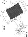
- a water intake structure in this example a Coand screen assembly 40.
- the assembly in this example is part of a hydropower plant 42.
- the plant includes a conduit, in this example a penstock 44 having an inlet 46.
- the plant 42 includes a barrier, in this example a dam 48 which extends across a body of water 50. The dam separates the water into a partially elevated upstream portion 52 and a downstream portion 54.
- the assembly 40 has a top 56, bottom 58 spaced-apart from the top, and pair of spaced-apart sides 60 and 62 extending between the top and bottom thereof.
- the assembly has a front 64 and a rear 66 spaced-apart from the front.
- the front and rear of the assembly 40 extend between the sides 60 and 62 of the assembly and between the top 56 and bottom 58 of the assembly.
- the assembly includes an upper member, in this example an accelerator plate 68 extending along the top 56 thereof and between the sides 60 and 62 thereof.
- the accelerator plate is elongate and semi-circular in lateral cross-section in this example, with an outwardly convex exterior top surface 69.
- the assembly 40 includes a lower member, in this example a runoff plate 70 extending along the bottom 58 thereof and between the sides 60 and 62 thereof.
- the runoff plate is elongate and has a right trapezoidal shape in lateral cross-section in this example; however this is not strictly required and the runoff plate may comprise other shapes in other embodiments.
- the assembly 40 includes a pair of side support members, in this example structural beams 72 and 74.
- the structural beams aligns with and extends along respective sides 60 and 62 of the assembly.
- the structural beams 72 and 74 couples to and extends between the accelerator plate 68 and runoff plate 70.
- the structural beams, accelerator plate and runoff plate form an enclosure 76 which is rectangular in this example.
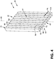
- the assembly 40 includes a water intake screen, in this example a Coand screen 78.
- the screen includes a plurality of longitudinally-extending elongate members, as shown by elongate members of numerals 80, 82 and 84.
- the elongate members extend parallel with each other and parallel with a horizontally-extending longitudinal axis 85 of the assembly 40 in this example.
- the screen 78 is positioned between the downstream portion 54 of the water 50 and the inlet 46 of the penstock 44. The screen is thus positioned downstream of the dam 48 and upstream portion 52 of the water 50.
- the screen 78 and elongate members 80, 82 and 84 extend between and couple to structural beams 72 and 74 seen in Figure 2 via welding 73 in this example. However, this is not strictly required and the elongate members may couple to the structural beams in other manners in other examples, such as via grooves in the structural beams, for example.
- the elongate members 80, 82 and 84, seen in Figure 3 are thus coupled together and extend between the sides 60 and 62 of the assembly 40 seen in Figure 2 .
- the screen 78 and elongate members thereof are also positioned and extend between the accelerator plate 68 and runoff plate 70.
- each elongate member 80 is generally wedge-shaped in lateral cross-section in this embodiment.
- the elongate members taper in a direction extending from the front 64 towards the rear 66 of the assembly 60 in this example; however this is not strictly required and the elongate members need not so taper in other embodiments.
- Each elongate member 80 has a first exterior or outer side or surface 86 aligned with and adjacent to the front of the assembly 60.
- the outer surfaces of the elongate members are outwardly convex in lateral profile in this embodiment.
- Each elongate member 80 has a second exterior or inner surface 88 aligned with and adjacent to the rear 66 of the assembly 60.
- the inner surfaces of the elongate members are spaced-apart from the outer surfaces 86 of the elongate members.
- the inner surfaces 88 of the elongate members 80 are narrower than the outer surfaces 86 of the elongate members in this embodiment.
- each elongate member 80 has a third exterior, top-facing or upstream-facing side or surface 90 that faces at least in part towards the top 56 of the assembly.
- the upstream-facing surfaces are outwardly concave in this embodiment.
- Each elongate member 80 has a fourth exterior, bottom-facing or downstream-facing side or surface 92 that faces at least in part towards the bottom 58 of the assembly 40.
- the downstream-facing surfaces of the elongate members are spaced-apart from the upstream-facing surfaces of the elongate members.
- the downstream-facing surfaces 92 are planar in this example and are sloped in this example relative to a vertical plane 79 and horizontal plane 81.
- the upstream-facing surfaces 90 and downstream-facing surfaces 92 of the elongate members 80 extend between the respective outer surfaces 86 and inner surfaces 88 of the elongate members.
- the upstream-facing surfaces and downstream-facing surfaces of the elongate members 80 are wider than the outer surfaces 86 of the elongate members in this embodiment.
- the surfaces 86, 88, 90 and 92 of the elongate members extend between the sides 60 and 62 of the assembly 40 seen in Figure 2 .
- each elongate member 80 has an upper or leading edge 93 between and adjacent outer surface 86 thereof and upstream-facing surface 90 thereof.
- Each elongate member includes an upper peripheral portion 95 extending between the outer surface 86 thereof and the upstream-facing surface 90 thereof.
- the upper peripheral portion of each elongate member is generally triangular in lateral profile and curved in lateral profile at least in part in this embodiment. In this example the upper peripheral portions 95 are outwardly convex in lateral profile in part in this example.
- the upper peripheral portions of the elongate members 80 so shaped may function to direct a flow of water towards an intake direction 101 and towards the inlet 46 of the penstock 44, between adjacent elongate members 80 and 82.
- each elongate member 80 includes a lower peripheral portion 99 extending between the outer surface 86 thereof and the downstream-facing surface 92 thereof.
- the lower peripheral portion is sloped relative to the upper peripheral portion 95 of the elongate member in this embodiment.
- the lower peripheral portion 99 of the elongate member is curved in lateral profile at least in part and in this example is outwardly concave in part in lateral profile.
- the lower peripheral portions of the elongate members so shaped may function to direct a flow of water towards the intake direction 101 and towards the inlet 46 of the penstock 44, between adjacent elongate members 80 and 82, before and instead of hitting the leading edge 97 of the next elongate member 82.
- the assembly 40 is positioned to enable water 50 to flow above and along the outer surfaces 86 of the elongate members 80, 82 and 84, as shown by arrow of numeral 87, and to intake portions 94 and 96 of the water between adjacent said elongate members 80 and 82, and 82 and 84.
- the portions of water abut the upstream-facing surfaces 90 of the elongate members.
- the elongate members 80, 82 and 84 are positioned to promote the Coand effect, with portions 94 and 96 of the water 50 being taken in thereby.
- each elongate member 80 thus may be said to have a three-sided cross section, with an upstream-facing side 90, a downstream-facing side 92, and an outer side 86.
- the upstream-facing side is outwardly concave, with a circular profile having a radius in the range of 20 mm to 200 mm in one preferred example, with the radius being equal to 100 mm according to one preferred embodiment.
- the downstream-facing side 92 is flat.
- the outer side 86 is outwardly convex, with a circular profile having a radius in the range of 10 mm to 250 mm, with the radius being equal to 60 mm in one preferred example.
- these ranges and dimensions may not be strictly required and the elongate members 80 may have other sizes in other embodiments, for example.
- upstream-facing side 90 of the elongate member extends downwards from and relative to outer side 86 of the elongate member by angle ⁇ .
- This angle is measured between the tangent directions of the circular profiles of the upstream-facing side 90 and the outer side 86.
- Angle ⁇ is in the range of 20 degrees to 110 degrees in one preferred example, with the angle ⁇ being equal to 65 degrees according to one preferred embodiment. However, these angles may not be strictly required and may have other values in other embodiments, for example.
- the leading edge 93 of the elongate member is sharp to promote and improve flow of water thereon and therepast.
- Rearward edge 89 and trailing edge 91 of the elongate member 80 may be sharp or slightly rounded.
- the elongate members are arranged in a repeating pattern, with the outer side 86 of each elongate member roughly parallel to the flow of water 50 over the screen assembly 40 as indicated by arrow 87.
- the assembly 40 includes a plurality of slots interposed between respective pairs of elongate members, as seen by slot 103 in Figure 4 .
- Each slot has a width Ws is in the range of 0.1 mm to 10 mm in one preferred example, with the slot width being equal to 1.5 mm according to one preferred embodiment. However, these ranges and dimensions may not be strictly required and may be equal to other values in other embodiments, for example.
- surface tension effects cause the water stream to cling to the rounded outer side 86 of the elongate member and turn towards the slot between the elongate members.
- FIGs 6 to 7 show a water intake structure, in this example a Coand screen assembly 40.1 for a hydropower plant 42.1 according to a second embodiment.
- Like parts have like numbers and functionings as the embodiment shown in Figures 1 to 5 with the addition of decimal extension ".1".
- Assembly 40.1 and hydropower plant 42.1 are substantially the same as assembly 40 and hydropower plant 42 shown in Figures 1 to 5 with the following exceptions.
- Each elongate member, in this example elongate member 80.1 has first and second exterior surfaces, in this case an outer surface 86.1 thereof and a downstream-facing surface 92.1 thereof which are both planar in this embodiment.
- the outer surface of each elongate member extends perpendicular with respect to the downstream-facing surface of the elongate member in this example.
- the outer surfaces 86.1 and downstream-facing surfaces 92.1 of the elongate members 80.1 are sloped in this example relative to the vertical plane 79.1 and horizontal plane 81.1.
- the outer surfaces of the elongate members are positioned to extend in parallel with the flow of water 50.1 thereon, with said flow being shown by arrow 87.1.
- Each elongate member 80.1 has a third exterior surface, in this example an upstream-facing surface 90.1 which is outwardly concave in lateral profile.
- the upper peripheral portions 95.1 of the elongate members are curved in lateral profile at least in part and in this example are outwardly concave in lateral profile in part.
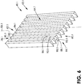
- FIGs 8 to 9 show a water intake structure, in this example a Coand screen assembly 40.2 for a hydropower plant 42.2 according to a third embodiment.
- Like parts have like numbers and functionings as the embodiment shown in Figures 1 to 5 with the addition of decimal extension ".2".
- Assembly 40.2 and hydropower plant 42.2 are substantially the same as assembly 40 and hydropower plant 42 shown in Figures 1 to 5 with the following exceptions.
- Each elongate member, in this example elongate member 80.2 is trapezoidal in lateral cross-section in this embodiment.
- the outer surfaces 86.2 of the elongate members extend in parallel with the respective inner surfaces 88.2 of the elongate members in this example.
- the outer surfaces of the elongate members are positioned to extend in parallel with the flow of water 50.2 thereon, with said flow being shown by arrow 87.2.
- the downstream-facing surfaces 92.2 of the elongate members 80.2 are planar in this embodiment.
- each outer surface 86.2 of the elongate members 80.2 has a width W B .
- the inner surfaces 88.2 of the elongate members have widths that are equal to or less than 0.5 x W B in this embodiment.
- Each elongate member 80.2 has an upstream-facing surface 90.2 that is outwardly concave in this embodiment.
- the upper peripheral portions 95.2 of the elongate members are curved in lateral profile at least in part and are outwardly concave in lateral profile in part in this example.
- Figure 10 shows one of a plurality of elongate members 80.3 of a water intake structure, in this example a Coand screen assembly 40.3 for a hydropower plant 42.3 according to a fourth embodiment.
- Like parts have like numbers and functionings as the embodiment shown in Figures 8 to 9 with the replacement of decimal extension ".2" with decimal extension “.3” and with the addition of decimal extension ".3” for parts not previously having decimal extensions.
- Assembly 40.3 and hydropower plant 42.3 are substantially the same as assembly 40.2 and hydropower plant 42.2 shown in Figures 8 to 9 with the following exception.
- the outer surfaces are positioned to extend in parallel with the flow of water 50.3 thereon, with said flow being shown by arrow 87.3.
- the upper peripheral portions 95.3 of the elongate members 80.3 are curved in lateral profile at least in part and in this example are outwardly concave in lateral profile in part.
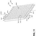
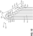
- FIGs 11 to 13 show a water intake structure, in this example a Coand screen assembly 40.4 for a hydropower plant 42.4 according to a fifth embodiment.
- Like parts have like numbers and functionings as the embodiment shown in Figures 8 to 9 with the replacement of decimal extension ".2" with decimal extension ".4" and with the addition of decimal extension ".4" for parts not previously having decimal extensions.
- Assembly 40.4 and hydropower plant 42.4 are substantially the same as assembly 40.2 and hydropower plant 42.2 shown in Figures 8 to 9 with the following exception.
- each of the elongate members in this example elongate member 80.4, has exterior surfaces 86.4, 88.4, 90.4 and 92.4 which form a parallelogram in shape in lateral cross-section in this embodiment.
- Each of the exterior surfaces of the elongate members is planar in this embodiment.
- Downstream-facing surface 92.4 extends parallel to upstream-facing surface 90.4 and outer surface 86.4 extends parallel to inner surface 88.4 of the elongate member in this embodiment.
- the outer surfaces 86.4 are positioned to extend in parallel with the flow of water 50.4 thereon, with said flow being shown by arrow 87.4.
- upstream-facing surface 90.4 of elongate member 80.4 extends downwards from the outer surface 86.4 of the elongate member at an acute angle ⁇ .4 relative to the outer surface. Angle ⁇ .4 is equal to 70 degrees in this example; however this is not strictly required and the angle may be different in other embodiments.
- Downstream-facing surface 92.4 of the elongate member extends from the outer surface 86.4 of the elongate member at an obtuse angle ⁇ relative to the outer surface. Angle ⁇ is equal to 110 degrees in this example; however this is not strictly required and this angle may be different in other embodiments.
- FIGs 14 to 16 show a water intake structure, in this example a Coand screen assembly 40.5 for a hydropower plant 42.5 according to a sixth embodiment. Like parts have like numbers and functionings as the embodiment shown in Figures 1 to 5 with the addition of decimal extension ".5". Assembly 40.5 and hydropower plant 42.5 are substantially the same as assembly 40 and hydropower plant 42 shown in Figures 1 to 5 with the following exceptions.
- Each elongate member, in this example elongate member 80.5 is generally wedge-shaped in lateral cross-section.
- each elongate member has first and second exterior surfaces, in this example upstream-facing surface 90.5 and downstream-facing surface 92.5, which are planar.
- the upstream-facing surface extends upwards from the downstream-facing surface at an acute angle ⁇ relative to the downstream-facing surface.
- Angle ⁇ is equal to 40 degrees in this example; however this is not strictly required and the angle may be different in other embodiments.
- Each elongate member 80.5 has a third exterior surface, in this example an outer surface 86.5 which is outwardly convex.
- the upper peripheral portions 95.5 of the elongate members are curved in lateral profile at least in part and in this example are outwardly convex in part in lateral profile.
- the lower peripheral portions 99.5 are of the elongate members 80.5 are sloped relative to the corresponding upper peripheral portions of the elongate members in this embodiment.
- the lower peripheral portions 99.5 of the elongate members are curved in lateral profile at least in part and in this example are outwardly convex in part in lateral profile.
- Figure 17 shows one of a plurality of elongate members 80.6 of a water intake structure, in this example a Coand screen assembly 40.6 for a hydropower plant 42.6 according to a seventh embodiment.
- Like parts have like numbers and functionings as the embodiment shown in Figures 14 to 16 with the replacement of decimal extension ".5" with decimal extension “.6” and with the addition of decimal extension ".6” for parts not previously having decimal extensions.
- Assembly 40.6 and hydropower plant 42.6 are substantially the same as assembly 40.5 and hydropower plant 42.5 shown in Figures 14 to 16 with the following exception.
- Each elongate member, in this example elongate member 80.6 is generally wedge-shaped in lateral cross-section. Each elongate member has an upper outer surface 86.6 adjacent to the upstream-facing surface 90.6 thereof. The upper outer surface is positioned to extend in parallel with the flow of water 50.6 thereon, with said flow being shown by arrow 87.6. Each elongate member 80.6 has a beveled edge, in this example a lower outer surface 98 extending between the upper outer surface 86.6 thereof and a downstream-facing surface 92.6 thereof. The lower outer surface 98 is thus adjacent to the downstream-facing surface 92.6 of the elongate member and is sloped relative to the upper outer surface 86.6 of the elongate member. Each elongate member 80.6 in this embodiment thus has a downstream beveled edge.
- the upstream-facing surface 90.6 of each elongate member extends downwards from upper outer surface 86.6 of the elongate member at an acute angle ⁇ .6 relative to the upper outer surface 86.6 of the elongate member.
- the upstream-facing surface 90.6 of each elongate member 80.6 extends upwards from the downstream-facing surface 92.6 of the elongate member at an acute angle ⁇ .6 relative to the downstream-facing surface in this example.
- the lower peripheral portions 99.6 of the elongate members 80.6 are sloped relative to the upper peripheral portions 95.6 of the elongate members in this embodiment.
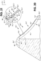
- FIGs 18 to 21 show a water intake structure, in this example a Coand screen assembly 40.7 for a hydropower plant 42.7 according to an eighth embodiment.
- Like parts have like numbers and functionings as the embodiment shown in Figures 1 to 5 with the addition of decimal extension ".7".
- Assembly 40.7 and hydropower plant 42.7 are substantially the same as assembly 40 and hydropower plant 42 shown in Figures 1 to 5 with the following exceptions.
- each elongate member, in this example elongate member 80.7 has an outer surface 86.7 that is outwardly convex in lateral profile.
- the outer surfaces face towards the front 64.7 of the assembly 40.7 in part and face towards the bottom 58.7 of the assembly in part in this example.
- Each elongate member 80.7 has an upstream-facing surface 90.7 that is outwardly concave in lateral profile in this embodiment.
- the outer surfaces 86.7 of the elongate members are wider than the upstream-facing surfaces of the elongate members and are wider than that the inner surfaces 88.7 of the elongate members in this example.
- the inner surfaces of the elongate members 80.7 are planar and sloped relative to the vertical plane 79.7 and horizontal plane 81.7.
- each elongate member 82.7 includes a top portion 100 and a bottom portion 102.
- the top portion 100 of elongate member 82.7 is adjacent to the bottom portion 102' of an adjacent elongate member 80.7.
- the upper peripheral portions 95.7 of the elongate members 80.7 are curved in lateral profile at least in part, outwardly convex in an upper section 104 thereof and outwardly concave in a lower section 106 thereof.
- the lower peripheral portions 99.7 of the elongate members are sloped relative to the upper peripheral portion 95.7 of the elongate members in this embodiment.
- the lower peripheral portions of the elongate members are curved in lateral profile at least in part and in this example are outwardly convex in lateral profile in part.
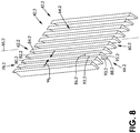
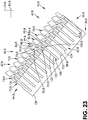
- Figures 22 to 25 show a water intake structure, in this example a Coand screen assembly 40.8 for a hydropower plant 42.8 according to a ninth embodiment.
- Like parts have like numbers and functionings as the embodiment shown in Figures 18 to 21 with decimal extension ".8" replacing decimal extension ".7” and being added for parts not previously having decimal extensions.
- Assembly 40.8 and hydropower plant 42.8 are substantially the same as assembly 40.7 and hydropower plant 42.7 shown in Figures 1 to 18 to 21 with the following exceptions.
- each elongate member 80.8 of the assembly includes an inner portion, in this example an elongate mount 108 that is rigid.
- the mounts in this example are made of metal, in this case steel plate; however, this is not strictly required and the mounts of the elongate members may be made of other rigid materials in other examples.
- the mounts are planar and in the form of rectangular prisms in this example.
- Each mount 108 has an upstream-facing surface 110 and a downstream-facing surface 112 each of which is planar, substantially similar in size and rectangular in this example.
- Each mount has a rear 114 which aligns with the inner surface 88.8 of the elongate member 80.8 and which is adjacent bottom 58.8 of the assembly 40.8.
- Each mount 108 has a front 116 spaced-apart from the rear thereof.
- the upstream-facing surface 110 and downstream-facing surface 112 extend between the front and rear of the mount.
- the front and rear of the mount are substantially in shape in this example.
- Each mount 108 includes a pair of sides, as seen by side 118 in Figure 22 , which extend between the rear 114 and front 116 thereof.
- the rear 114, front 116 and sides 118 of the mount each have widths W M that are substantially the same in this example.
- the assembly 40.8 includes one or more supports, in this example structural beams 72.8 and 74.8.
- At least one beam 72.8 has a plurality of longitudinally spaced-apart grooves 120, 122 and 124 extending therein from the front or top 126 thereof towards the rear or bottom 128 thereof.
- Each elongate member 80.8 is selectively received within a respective said groove 120 via first or bottom portion 122 of mount 108.
- the side framing is thus slotted to hold the elongate members in place.
- the assembly 40.8 so configured enables selective replacement only those parts thereof, in this case selective elongate members 80.8 that wear more significantly over time instead of requiring replacement of the assembly as a whole.
- each elongate member 80.8 includes an outer portion, in this example an elongate outer cap 125 along and upon which water flows.
- the outer caps are made of an elastomer, in this example rubber, which may provide improved abrasion resistance and be relatively less expensive to manufacture compared to steel for the custom shape of the outer caps. However, this is not strictly required and the outer caps may be made of other materials and be arranged in other configurations in other embodiments.
- each cap 125 has a rear or inner surface 127 and a groove 129 which extends from the inner surface towards the outer surface 86.8 of the elongate member 80.8
- the outer cap may be made of other polymers, such as a thermoplastic polymer, for example high-density polyethylene (HDPE), which may provide a similar wear performance to steel but with a significant cost saving compared to steel.
- a thermoplastic polymer for example high-density polyethylene (HDPE)
- HDPE high-density polyethylene
- each elongate member comprise a single intergrated and unitary whole, such as an elongate member wholly made of steel.
- each elongate member 80.8 has an outer surface 86.8 with a streamlined shape shaped to gradually alter a path 87.8 of water 50.8 extending therealong.
- the outer surfaces of the elongate members are shaped to promote development of a boundary layer of water thereon and inhibit creation of eddies thereon.
- the outer surfaces 86.8 of the elongate members 80.8 are curved at least in part and in this example are outwardly convex.
- the upstream-facing surfaces 90.8 of the elongate are curved at least in part and in this example are outwardly concave in part.
- the outer surface and the upstream-facing surface of each elongate member are thus both curved at least in part in this embodiment.
- the upstream-facing surface extends downwards from the outer surface 86.8 thereof at an acute angle ⁇ .8 relative to the outer surface thereof.
- the upper peripheral portion 95.8 of each elongate member 80.8 is generally triangular in shape in lateral profile in this example.
- the lower peripheral portions 99.8 of the elongate members are outwardly convex in lateral profile in this example, with trailing edges 91.8 of the elongate members being rounded in this example.
- the assemblies as herein described, with their elongate members thereof may comprise improved Coand screens optimized to take advantage of Coand and surface-tension effects.
- the assemblies as herein described, with their elongate members thereof may function to: increase water intake capacity per unit area of screen; decrease elongate member profile erosion by sediment; decrease sensitivity to elongate member profile erosion by sediment; decrease sensitivity to plugging by organic material; and/or increase self-cleaning capabilities.
- the assemblies herein described use the Coand effect on the scale of the individual elongate members as opposed to slicing the fluid.
- the assemblies as herein described may use surface-tension effects or the Coand effect to begin redirecting the water as it flows over the top of each elongate member, and not rely solely on the leading edge of the elongate member to turn the water flow. This may allow the leading edge of each elongate member to be effectively hidden behind the furthest protrusion of the next upstream elongate member into the water flow, deflecting rocks, sand, and organic debris away from the sharp edge of the screen. This may function to reduce wear on the leading edge of each elongate member and reduce the amount of organic debris that catches between the elongate members and plugs up the screen.
- the structures as herein described may result in improved durability by using the stickiness of fully developed flow as opposed to prior art systems which slice undeveloped flow. This may result in the structures as herein described being less reliant on the sharpness of the leading edge of the screen profile. Since the leading edge may erode over time due to sediment, this may result in structures as herein described which are more long-lasting.
- the intake screen is not only applicable to hydropower plants, but can also be applied to any form of water intake structure such as a drinking water intake, cooling water intake, or industrial process water intake, for example.
Landscapes
- Engineering & Computer Science (AREA)
- General Engineering & Computer Science (AREA)
- Mechanical Engineering (AREA)
- Civil Engineering (AREA)
- Structural Engineering (AREA)
- Hydraulic Turbines (AREA)
- Other Liquid Machine Or Engine Such As Wave Power Use (AREA)
- Nozzles (AREA)
Applications Claiming Priority (2)
| Application Number | Priority Date | Filing Date | Title |
|---|---|---|---|
| US201962860863P | 2019-06-13 | 2019-06-13 | |
| EP20179251.2A EP3751056B1 (fr) | 2019-06-13 | 2020-06-10 | Structure d'admission d'eau |
Related Parent Applications (2)
| Application Number | Title | Priority Date | Filing Date |
|---|---|---|---|
| EP20179251.2A Division EP3751056B1 (fr) | 2019-06-13 | 2020-06-10 | Structure d'admission d'eau |
| EP20179251.2A Division-Into EP3751056B1 (fr) | 2019-06-13 | 2020-06-10 | Structure d'admission d'eau |
Publications (3)
| Publication Number | Publication Date |
|---|---|
| EP3896228A1 true EP3896228A1 (fr) | 2021-10-20 |
| EP3896228B1 EP3896228B1 (fr) | 2023-11-01 |
| EP3896228C0 EP3896228C0 (fr) | 2023-11-01 |
Family
ID=71083542
Family Applications (2)
| Application Number | Title | Priority Date | Filing Date |
|---|---|---|---|
| EP20179251.2A Active EP3751056B1 (fr) | 2019-06-13 | 2020-06-10 | Structure d'admission d'eau |
| EP21179028.2A Active EP3896228B1 (fr) | 2019-06-13 | 2020-06-10 | Structure d'admission d'eau |
Family Applications Before (1)
| Application Number | Title | Priority Date | Filing Date |
|---|---|---|---|
| EP20179251.2A Active EP3751056B1 (fr) | 2019-06-13 | 2020-06-10 | Structure d'admission d'eau |
Country Status (3)
| Country | Link |
|---|---|
| US (1) | US11066798B2 (fr) |
| EP (2) | EP3751056B1 (fr) |
| CA (1) | CA3082768C (fr) |
Families Citing this family (8)
| Publication number | Priority date | Publication date | Assignee | Title |
|---|---|---|---|---|
| NO348078B1 (en) * | 2017-11-06 | 2024-08-12 | Fasseland Mekaniske Verksted As | An Inlet Screen for a Hydropower Plant |
| CA3077753C (fr) * | 2019-04-12 | 2026-02-03 | Cameron Farms Hutterite Colony | Appareil de pompage de fluide et modes d`utilisation |
| CN111035983B (zh) * | 2020-01-06 | 2024-07-05 | 湖南三友环保科技有限公司 | 一种用于生物硅藻土混合液中杂质去除的过滤装置 |
| EP4039087A1 (fr) * | 2021-02-09 | 2022-08-10 | ETH Zurich | Structure de guidage de poissons |
| AU2021204102A1 (en) * | 2021-06-18 | 2023-01-19 | Rain Harvesting Pty Ltd | Rain head and screen therefor |
| US12320087B2 (en) * | 2021-07-14 | 2025-06-03 | The United States Of America As Represented By The Secretary Of Agriculture | Submerged liquid intake strainers |
| US11471796B1 (en) * | 2022-03-25 | 2022-10-18 | Robert Sherwood | Filtration system for a water drainage system |
| JP7746617B1 (ja) * | 2025-03-26 | 2025-09-30 | 株式会社ナガオカ | 取水パネルおよび取水パネルの製造法 |
Citations (9)
| Publication number | Priority date | Publication date | Assignee | Title |
|---|---|---|---|---|
| WO1994017896A1 (fr) * | 1993-02-11 | 1994-08-18 | Stephen Crompton | Appareil de separation de matieres solides a partir d'un liquide en ecoulement |
| US20040099583A1 (en) * | 2001-10-24 | 2004-05-27 | Frey Frejborg | Screen cylinder with performance boosting configuration |
| US20050246967A1 (en) | 2004-04-06 | 2005-11-10 | Esmond Steven E | Rain and storm water filtration systems |
| US20080101867A1 (en) | 2006-10-26 | 2008-05-01 | Mclaughlin Richard Evan | Water Diversion System And Method Having Hydraulic Chute, Screen Assembly And Wedge Wire Screen |
| KR20120131331A (ko) * | 2011-05-25 | 2012-12-05 | 이소라 | 수처리 구조물 |
| CH708046A2 (de) * | 2013-05-08 | 2014-11-14 | Marcel Höhener | Coanda Wasserfassung mit Halbrundprofilen. |
| EP3023165A1 (fr) | 2014-11-19 | 2016-05-25 | Stocker Mechatronik GmbH | Tamis à fentes |
| CH713881B1 (de) | 2017-07-26 | 2018-12-14 | Marcel Hoehener | Spaltsieb für eine Einrichtung zur Wasserfassung und/oder Wasserfilterung. |
| WO2019220469A1 (fr) * | 2018-05-18 | 2019-11-21 | Wild Metal Srl | Grille fine racing adaptée pour être intégrée dans une prise d'eau |
Family Cites Families (21)
| Publication number | Priority date | Publication date | Assignee | Title |
|---|---|---|---|---|
| US2827169A (en) | 1954-12-07 | 1958-03-18 | Internat Pulp Products Inc | Screen plate |
| DE2714496C2 (de) | 1977-03-31 | 1986-03-06 | Kraftwerk Union AG, 4330 Mülheim | Siebkörper zum Abscheiden von Feststoffen aus gasförmigen Medien |
| JPS5474560A (en) * | 1977-11-28 | 1979-06-14 | Toray Ind Inc | Solid-liquid separating material |
| US4250038A (en) | 1978-07-21 | 1981-02-10 | Bixby-Zimmer Engineering Co. | Screen device and method |
| US4415462A (en) | 1982-08-12 | 1983-11-15 | Finch Harvey E | Self-cleaning screen |
| AU623740B2 (en) * | 1989-03-02 | 1992-05-21 | Ciba-Geigy Ag | Apparatus for the desludging of baths |
| US5047148A (en) | 1990-04-24 | 1991-09-10 | Koichi Arai | Retained wire filter element |
| US5385240A (en) | 1993-04-30 | 1995-01-31 | The Black Clawson Company | Screening apparatus with adjustable hydrofoil portion |
| US5674386A (en) * | 1996-06-13 | 1997-10-07 | John Meunier Inc. | Self-cleaning bar screen for storm water and the like large water volumes |
| US6595373B1 (en) | 1998-10-06 | 2003-07-22 | Kadant Black Clawson, Inc. | Wedge wire and paper stock screening apparatus incorporating such wedge wire |
| US6151837A (en) | 1998-11-06 | 2000-11-28 | Ealer, Sr.; James Edward | Perforated sheet gutter screen |
| WO2000065151A1 (fr) | 1999-04-27 | 2000-11-02 | Cae Screenplates, Inc. | Profil de fil metallique profile a fonctionnalite amelioree |
| US6698595B2 (en) * | 2001-04-19 | 2004-03-02 | Weatherford/Lamb, Inc. | Screen material |
| WO2007094967A1 (fr) | 2006-02-16 | 2007-08-23 | Kadant Black Clawson Inc. | film DE PROTECTION en pâte et procédé d'utilisation |
| JP4395190B2 (ja) | 2008-02-19 | 2010-01-06 | 株式会社ハネックス | 分離装置及び分離方法 |
| US20110146802A1 (en) | 2009-02-17 | 2011-06-23 | C-Water Technologies, Inc. | Water intake structure |
| US8282836B2 (en) * | 2009-02-17 | 2012-10-09 | C-Water Technologies, Inc. | Water intake structure |
| JP5031866B2 (ja) | 2010-05-12 | 2012-09-26 | 株式会社エス・アール・エム技術開発 | ウェッジワイヤースクリーン装置 |
| US8887925B2 (en) | 2010-06-25 | 2014-11-18 | Abbas Motakef | Wedge bar for inertial separation |
| FR2975444B1 (fr) * | 2011-05-17 | 2016-12-23 | Mj2 Tech | Centrale hydraulique comportant un ensemble a grille d'admission d'eau dans la turbine agence pour evacuer des debris flottants arretes par la grille. |
| WO2015112727A1 (fr) * | 2014-01-22 | 2015-07-30 | Dayton Hydro Electric Ltd. | Systèmes et procédés pour systèmes hydroélectriques |
-
2020
- 2020-06-08 US US16/896,116 patent/US11066798B2/en active Active
- 2020-06-09 CA CA3082768A patent/CA3082768C/fr active Active
- 2020-06-10 EP EP20179251.2A patent/EP3751056B1/fr active Active
- 2020-06-10 EP EP21179028.2A patent/EP3896228B1/fr active Active
Patent Citations (9)
| Publication number | Priority date | Publication date | Assignee | Title |
|---|---|---|---|---|
| WO1994017896A1 (fr) * | 1993-02-11 | 1994-08-18 | Stephen Crompton | Appareil de separation de matieres solides a partir d'un liquide en ecoulement |
| US20040099583A1 (en) * | 2001-10-24 | 2004-05-27 | Frey Frejborg | Screen cylinder with performance boosting configuration |
| US20050246967A1 (en) | 2004-04-06 | 2005-11-10 | Esmond Steven E | Rain and storm water filtration systems |
| US20080101867A1 (en) | 2006-10-26 | 2008-05-01 | Mclaughlin Richard Evan | Water Diversion System And Method Having Hydraulic Chute, Screen Assembly And Wedge Wire Screen |
| KR20120131331A (ko) * | 2011-05-25 | 2012-12-05 | 이소라 | 수처리 구조물 |
| CH708046A2 (de) * | 2013-05-08 | 2014-11-14 | Marcel Höhener | Coanda Wasserfassung mit Halbrundprofilen. |
| EP3023165A1 (fr) | 2014-11-19 | 2016-05-25 | Stocker Mechatronik GmbH | Tamis à fentes |
| CH713881B1 (de) | 2017-07-26 | 2018-12-14 | Marcel Hoehener | Spaltsieb für eine Einrichtung zur Wasserfassung und/oder Wasserfilterung. |
| WO2019220469A1 (fr) * | 2018-05-18 | 2019-11-21 | Wild Metal Srl | Grille fine racing adaptée pour être intégrée dans une prise d'eau |
Also Published As
| Publication number | Publication date |
|---|---|
| EP3896228B1 (fr) | 2023-11-01 |
| EP3896228C0 (fr) | 2023-11-01 |
| CA3082768A1 (fr) | 2020-12-13 |
| CA3082768C (fr) | 2022-05-03 |
| EP3751056C0 (fr) | 2023-10-25 |
| EP3751056B1 (fr) | 2023-10-25 |
| EP3751056A1 (fr) | 2020-12-16 |
| US11066798B2 (en) | 2021-07-20 |
| US20200392687A1 (en) | 2020-12-17 |
Similar Documents
| Publication | Publication Date | Title |
|---|---|---|
| EP3751056B1 (fr) | Structure d'admission d'eau | |
| US12371866B2 (en) | Fish guidance structure | |
| US10227768B2 (en) | Resistance screens for use in storm drain filtration systems | |
| US8734053B1 (en) | Articulated baffle assembly | |
| CA2206858C (fr) | Grille a barreaux auto-nettoyante pour eaux d'orage et autres importants volumes d'eau de semblable origine | |
| US8075787B2 (en) | Protective sleeve for intake rack bars | |
| CN108385605A (zh) | 一种海堤挡浪结构及其施工方法 | |
| KR101794162B1 (ko) | 부유물 수집부가 구비된 부유물 거름 시설 | |
| KR100949384B1 (ko) | 제진기 스크린 | |
| US6196762B1 (en) | Non-clogging debris and sediment removal facility | |
| JP3120072B2 (ja) | 渓流取水用傾斜スクリーン | |
| JP2012140845A (ja) | 上下2段構造の分流装置 | |
| CN213868058U (zh) | 一种野外水源点的无坝自净化取水装置 | |
| JPH07127041A (ja) | ダム貯水池の流入水分離装置 | |
| JP2003064639A (ja) | 取水装置 | |
| CN212651397U (zh) | 立体斜板净化装置及具有该净化装置的沉淀池 | |
| CN112982556A (zh) | 一种曲线型底栏栅取水结构 | |
| CN223738435U (zh) | 一种适配高陡边坡地表排水沟的装配式跌水防溅装置 | |
| CN212103923U (zh) | 一种渠道弯道处施工用模板 | |
| CN223780953U (zh) | 一种截污装置 | |
| JP2538795Y2 (ja) | 水路のスクリーン装置 | |
| David et al. | Spacing: Physical Barriers | |
| JP4545476B2 (ja) | 水力発電用導水路 | |
| Raleigh | How to mitigate the effects of scour on bridge piers through the use of combined countermeasures | |
| CN121802794A (zh) | 泥石流分级拦挡排导槽及侧向清淤系统 |
Legal Events
| Date | Code | Title | Description |
|---|---|---|---|
| PUAI | Public reference made under article 153(3) epc to a published international application that has entered the european phase |
Free format text: ORIGINAL CODE: 0009012 |
|
| STAA | Information on the status of an ep patent application or granted ep patent |
Free format text: STATUS: REQUEST FOR EXAMINATION WAS MADE |
|
| 17P | Request for examination filed |
Effective date: 20210611 |
|
| AC | Divisional application: reference to earlier application |
Ref document number: 3751056 Country of ref document: EP Kind code of ref document: P |
|
| AK | Designated contracting states |
Kind code of ref document: A1 Designated state(s): AL AT BE BG CH CY CZ DE DK EE ES FI FR GB GR HR HU IE IS IT LI LT LU LV MC MK MT NL NO PL PT RO RS SE SI SK SM TR |
|
| B565 | Issuance of search results under rule 164(2) epc |
Effective date: 20210901 |
|
| GRAP | Despatch of communication of intention to grant a patent |
Free format text: ORIGINAL CODE: EPIDOSNIGR1 |
|
| STAA | Information on the status of an ep patent application or granted ep patent |
Free format text: STATUS: GRANT OF PATENT IS INTENDED |
|
| INTG | Intention to grant announced |
Effective date: 20230619 |
|
| GRAS | Grant fee paid |
Free format text: ORIGINAL CODE: EPIDOSNIGR3 |
|
| GRAA | (expected) grant |
Free format text: ORIGINAL CODE: 0009210 |
|
| STAA | Information on the status of an ep patent application or granted ep patent |
Free format text: STATUS: THE PATENT HAS BEEN GRANTED |
|
| AC | Divisional application: reference to earlier application |
Ref document number: 3751056 Country of ref document: EP Kind code of ref document: P |
|
| AK | Designated contracting states |
Kind code of ref document: B1 Designated state(s): AL AT BE BG CH CY CZ DE DK EE ES FI FR GB GR HR HU IE IS IT LI LT LU LV MC MK MT NL NO PL PT RO RS SE SI SK SM TR |
|
| REG | Reference to a national code |
Ref country code: GB Ref legal event code: FG4D |
|
| REG | Reference to a national code |
Ref country code: CH Ref legal event code: EP |
|
| REG | Reference to a national code |
Ref country code: IE Ref legal event code: FG4D |
|
| REG | Reference to a national code |
Ref country code: DE Ref legal event code: R096 Ref document number: 602020020520 Country of ref document: DE |
|
| U01 | Request for unitary effect filed |
Effective date: 20231117 |
|
| U07 | Unitary effect registered |
Designated state(s): AT BE BG DE DK EE FI FR IT LT LU LV MT NL PT SE SI Effective date: 20231123 |
|
| REG | Reference to a national code |
Ref country code: NO Ref legal event code: T2 Effective date: 20231101 |
|
| PG25 | Lapsed in a contracting state [announced via postgrant information from national office to epo] |
Ref country code: GR Free format text: LAPSE BECAUSE OF FAILURE TO SUBMIT A TRANSLATION OF THE DESCRIPTION OR TO PAY THE FEE WITHIN THE PRESCRIBED TIME-LIMIT Effective date: 20240202 |
|
| PG25 | Lapsed in a contracting state [announced via postgrant information from national office to epo] |
Ref country code: IS Free format text: LAPSE BECAUSE OF FAILURE TO SUBMIT A TRANSLATION OF THE DESCRIPTION OR TO PAY THE FEE WITHIN THE PRESCRIBED TIME-LIMIT Effective date: 20240301 |
|
| PG25 | Lapsed in a contracting state [announced via postgrant information from national office to epo] |
Ref country code: ES Free format text: LAPSE BECAUSE OF FAILURE TO SUBMIT A TRANSLATION OF THE DESCRIPTION OR TO PAY THE FEE WITHIN THE PRESCRIBED TIME-LIMIT Effective date: 20231101 |
|
| PG25 | Lapsed in a contracting state [announced via postgrant information from national office to epo] |
Ref country code: IS Free format text: LAPSE BECAUSE OF FAILURE TO SUBMIT A TRANSLATION OF THE DESCRIPTION OR TO PAY THE FEE WITHIN THE PRESCRIBED TIME-LIMIT Effective date: 20240301 Ref country code: GR Free format text: LAPSE BECAUSE OF FAILURE TO SUBMIT A TRANSLATION OF THE DESCRIPTION OR TO PAY THE FEE WITHIN THE PRESCRIBED TIME-LIMIT Effective date: 20240202 Ref country code: ES Free format text: LAPSE BECAUSE OF FAILURE TO SUBMIT A TRANSLATION OF THE DESCRIPTION OR TO PAY THE FEE WITHIN THE PRESCRIBED TIME-LIMIT Effective date: 20231101 |
|
| PG25 | Lapsed in a contracting state [announced via postgrant information from national office to epo] |
Ref country code: RS Free format text: LAPSE BECAUSE OF FAILURE TO SUBMIT A TRANSLATION OF THE DESCRIPTION OR TO PAY THE FEE WITHIN THE PRESCRIBED TIME-LIMIT Effective date: 20231101 Ref country code: PL Free format text: LAPSE BECAUSE OF FAILURE TO SUBMIT A TRANSLATION OF THE DESCRIPTION OR TO PAY THE FEE WITHIN THE PRESCRIBED TIME-LIMIT Effective date: 20231101 Ref country code: HR Free format text: LAPSE BECAUSE OF FAILURE TO SUBMIT A TRANSLATION OF THE DESCRIPTION OR TO PAY THE FEE WITHIN THE PRESCRIBED TIME-LIMIT Effective date: 20231101 |
|
| PG25 | Lapsed in a contracting state [announced via postgrant information from national office to epo] |
Ref country code: CZ Free format text: LAPSE BECAUSE OF FAILURE TO SUBMIT A TRANSLATION OF THE DESCRIPTION OR TO PAY THE FEE WITHIN THE PRESCRIBED TIME-LIMIT Effective date: 20231101 |
|
| PG25 | Lapsed in a contracting state [announced via postgrant information from national office to epo] |
Ref country code: SK Free format text: LAPSE BECAUSE OF FAILURE TO SUBMIT A TRANSLATION OF THE DESCRIPTION OR TO PAY THE FEE WITHIN THE PRESCRIBED TIME-LIMIT Effective date: 20231101 |
|
| PG25 | Lapsed in a contracting state [announced via postgrant information from national office to epo] |
Ref country code: SM Free format text: LAPSE BECAUSE OF FAILURE TO SUBMIT A TRANSLATION OF THE DESCRIPTION OR TO PAY THE FEE WITHIN THE PRESCRIBED TIME-LIMIT Effective date: 20231101 Ref country code: SK Free format text: LAPSE BECAUSE OF FAILURE TO SUBMIT A TRANSLATION OF THE DESCRIPTION OR TO PAY THE FEE WITHIN THE PRESCRIBED TIME-LIMIT Effective date: 20231101 Ref country code: CZ Free format text: LAPSE BECAUSE OF FAILURE TO SUBMIT A TRANSLATION OF THE DESCRIPTION OR TO PAY THE FEE WITHIN THE PRESCRIBED TIME-LIMIT Effective date: 20231101 |
|
| U20 | Renewal fee for the european patent with unitary effect paid |
Year of fee payment: 5 Effective date: 20240627 |
|
| REG | Reference to a national code |
Ref country code: DE Ref legal event code: R097 Ref document number: 602020020520 Country of ref document: DE |
|
| PLBE | No opposition filed within time limit |
Free format text: ORIGINAL CODE: 0009261 |
|
| STAA | Information on the status of an ep patent application or granted ep patent |
Free format text: STATUS: NO OPPOSITION FILED WITHIN TIME LIMIT |
|
| 26N | No opposition filed |
Effective date: 20240802 |
|
| PG25 | Lapsed in a contracting state [announced via postgrant information from national office to epo] |
Ref country code: MC Free format text: LAPSE BECAUSE OF FAILURE TO SUBMIT A TRANSLATION OF THE DESCRIPTION OR TO PAY THE FEE WITHIN THE PRESCRIBED TIME-LIMIT Effective date: 20231101 |
|
| REG | Reference to a national code |
Ref country code: CH Ref legal event code: PL |
|
| PG25 | Lapsed in a contracting state [announced via postgrant information from national office to epo] |
Ref country code: IE Free format text: LAPSE BECAUSE OF NON-PAYMENT OF DUE FEES Effective date: 20240610 |
|
| PG25 | Lapsed in a contracting state [announced via postgrant information from national office to epo] |
Ref country code: CH Free format text: LAPSE BECAUSE OF NON-PAYMENT OF DUE FEES Effective date: 20240630 |
|
| PG25 | Lapsed in a contracting state [announced via postgrant information from national office to epo] |
Ref country code: RO Free format text: LAPSE BECAUSE OF FAILURE TO SUBMIT A TRANSLATION OF THE DESCRIPTION OR TO PAY THE FEE WITHIN THE PRESCRIBED TIME-LIMIT Effective date: 20231101 |
|
| PG25 | Lapsed in a contracting state [announced via postgrant information from national office to epo] |
Ref country code: CY Free format text: LAPSE BECAUSE OF FAILURE TO SUBMIT A TRANSLATION OF THE DESCRIPTION OR TO PAY THE FEE WITHIN THE PRESCRIBED TIME-LIMIT; INVALID AB INITIO Effective date: 20200610 |
|
| U21 | Renewal fee for the european patent with unitary effect paid with additional fee |
Year of fee payment: 6 Effective date: 20251126 |
|
| PGFP | Annual fee paid to national office [announced via postgrant information from national office to epo] |
Ref country code: GB Payment date: 20251127 Year of fee payment: 6 |
|
| PGFP | Annual fee paid to national office [announced via postgrant information from national office to epo] |
Ref country code: NO Payment date: 20251128 Year of fee payment: 6 |
|
| PG25 | Lapsed in a contracting state [announced via postgrant information from national office to epo] |
Ref country code: HU Free format text: LAPSE BECAUSE OF FAILURE TO SUBMIT A TRANSLATION OF THE DESCRIPTION OR TO PAY THE FEE WITHIN THE PRESCRIBED TIME-LIMIT; INVALID AB INITIO Effective date: 20200610 |