EP3896254B1 - Aube multi-matériaux pour un moteur à turbine à gaz - Google Patents
Aube multi-matériaux pour un moteur à turbine à gaz Download PDFInfo
- Publication number
- EP3896254B1 EP3896254B1 EP21168985.6A EP21168985A EP3896254B1 EP 3896254 B1 EP3896254 B1 EP 3896254B1 EP 21168985 A EP21168985 A EP 21168985A EP 3896254 B1 EP3896254 B1 EP 3896254B1
- Authority
- EP
- European Patent Office
- Prior art keywords
- vane
- airfoil
- section
- side section
- base section
- Prior art date
- Legal status (The legal status is an assumption and is not a legal conclusion. Google has not performed a legal analysis and makes no representation as to the accuracy of the status listed.)
- Active
Links
Images



Classifications
-
- F—MECHANICAL ENGINEERING; LIGHTING; HEATING; WEAPONS; BLASTING
- F01—MACHINES OR ENGINES IN GENERAL; ENGINE PLANTS IN GENERAL; STEAM ENGINES
- F01D—NON-POSITIVE DISPLACEMENT MACHINES OR ENGINES, e.g. STEAM TURBINES
- F01D9/00—Stators
- F01D9/02—Nozzles; Nozzle boxes; Stator blades; Guide conduits, e.g. individual nozzles
- F01D9/04—Nozzles; Nozzle boxes; Stator blades; Guide conduits, e.g. individual nozzles forming ring or sector
- F01D9/041—Nozzles; Nozzle boxes; Stator blades; Guide conduits, e.g. individual nozzles forming ring or sector using blades
-
- F—MECHANICAL ENGINEERING; LIGHTING; HEATING; WEAPONS; BLASTING
- F01—MACHINES OR ENGINES IN GENERAL; ENGINE PLANTS IN GENERAL; STEAM ENGINES
- F01D—NON-POSITIVE DISPLACEMENT MACHINES OR ENGINES, e.g. STEAM TURBINES
- F01D9/00—Stators
- F01D9/02—Nozzles; Nozzle boxes; Stator blades; Guide conduits, e.g. individual nozzles
-
- F—MECHANICAL ENGINEERING; LIGHTING; HEATING; WEAPONS; BLASTING
- F01—MACHINES OR ENGINES IN GENERAL; ENGINE PLANTS IN GENERAL; STEAM ENGINES
- F01D—NON-POSITIVE DISPLACEMENT MACHINES OR ENGINES, e.g. STEAM TURBINES
- F01D25/00—Component parts, details, or accessories, not provided for in, or of interest apart from, other groups
- F01D25/005—Selecting particular materials
-
- F—MECHANICAL ENGINEERING; LIGHTING; HEATING; WEAPONS; BLASTING
- F01—MACHINES OR ENGINES IN GENERAL; ENGINE PLANTS IN GENERAL; STEAM ENGINES
- F01D—NON-POSITIVE DISPLACEMENT MACHINES OR ENGINES, e.g. STEAM TURBINES
- F01D5/00—Blades; Blade-carrying members; Heating, heat-insulating, cooling or antivibration means on the blades or the members
- F01D5/12—Blades
- F01D5/28—Selecting particular materials; Particular measures relating thereto; Measures against erosion or corrosion
- F01D5/282—Selecting composite materials, e.g. blades with reinforcing filaments
-
- F—MECHANICAL ENGINEERING; LIGHTING; HEATING; WEAPONS; BLASTING
- F05—INDEXING SCHEMES RELATING TO ENGINES OR PUMPS IN VARIOUS SUBCLASSES OF CLASSES F01-F04
- F05D—INDEXING SCHEME FOR ASPECTS RELATING TO NON-POSITIVE-DISPLACEMENT MACHINES OR ENGINES, GAS-TURBINES OR JET-PROPULSION PLANTS
- F05D2240/00—Components
- F05D2240/10—Stators
- F05D2240/12—Fluid guiding means, e.g. vanes
- F05D2240/121—Fluid guiding means, e.g. vanes related to the leading edge of a stator vane
-
- F—MECHANICAL ENGINEERING; LIGHTING; HEATING; WEAPONS; BLASTING
- F05—INDEXING SCHEMES RELATING TO ENGINES OR PUMPS IN VARIOUS SUBCLASSES OF CLASSES F01-F04
- F05D—INDEXING SCHEME FOR ASPECTS RELATING TO NON-POSITIVE-DISPLACEMENT MACHINES OR ENGINES, GAS-TURBINES OR JET-PROPULSION PLANTS
- F05D2240/00—Components
- F05D2240/10—Stators
- F05D2240/12—Fluid guiding means, e.g. vanes
- F05D2240/122—Fluid guiding means, e.g. vanes related to the trailing edge of a stator vane
-
- F—MECHANICAL ENGINEERING; LIGHTING; HEATING; WEAPONS; BLASTING
- F05—INDEXING SCHEMES RELATING TO ENGINES OR PUMPS IN VARIOUS SUBCLASSES OF CLASSES F01-F04
- F05D—INDEXING SCHEME FOR ASPECTS RELATING TO NON-POSITIVE-DISPLACEMENT MACHINES OR ENGINES, GAS-TURBINES OR JET-PROPULSION PLANTS
- F05D2240/00—Components
- F05D2240/10—Stators
- F05D2240/12—Fluid guiding means, e.g. vanes
- F05D2240/123—Fluid guiding means, e.g. vanes related to the pressure side of a stator vane
-
- F—MECHANICAL ENGINEERING; LIGHTING; HEATING; WEAPONS; BLASTING
- F05—INDEXING SCHEMES RELATING TO ENGINES OR PUMPS IN VARIOUS SUBCLASSES OF CLASSES F01-F04
- F05D—INDEXING SCHEME FOR ASPECTS RELATING TO NON-POSITIVE-DISPLACEMENT MACHINES OR ENGINES, GAS-TURBINES OR JET-PROPULSION PLANTS
- F05D2240/00—Components
- F05D2240/10—Stators
- F05D2240/12—Fluid guiding means, e.g. vanes
- F05D2240/124—Fluid guiding means, e.g. vanes related to the suction side of a stator vane
-
- Y—GENERAL TAGGING OF NEW TECHNOLOGICAL DEVELOPMENTS; GENERAL TAGGING OF CROSS-SECTIONAL TECHNOLOGIES SPANNING OVER SEVERAL SECTIONS OF THE IPC; TECHNICAL SUBJECTS COVERED BY FORMER USPC CROSS-REFERENCE ART COLLECTIONS [XRACs] AND DIGESTS
- Y02—TECHNOLOGIES OR APPLICATIONS FOR MITIGATION OR ADAPTATION AGAINST CLIMATE CHANGE
- Y02T—CLIMATE CHANGE MITIGATION TECHNOLOGIES RELATED TO TRANSPORTATION
- Y02T50/00—Aeronautics or air transport
- Y02T50/60—Efficient propulsion technologies, e.g. for aircraft
Definitions
- This disclosure (invention) relates generally to a gas turbine engine and, more particularly, to a vane / vane assembly for a gas turbine engine.
- vanes such as structural guide vanes for a gas turbine engine
- these known vanes have various benefits, there is still room in the art for improvement.
- a light weight structural guide vane which is relatively simple to manufacture.
- U.S. Publication No. 2017/0292531 discloses subject matter according to the preamble of claim 1.
- a vane is provided for a gas turbine engine as claimed in claim 1.
- FIGS. 1 and 2 illustrate a multi-material vane 20 (e.g., a metal-composite vane) for a gas turbine engine.
- This vane 20 may be configured as a structural guide vane; e.g., a structural exit guide vane.
- the vane 20 may extend between and be structurally tied to an inner structure 22 of the gas turbine engine and an outer structure 24 of the gas turbine engine. With such a configuration, the vane 20 is configured to transfer loads between the inner structure 22 and the outer structure 24.
- the vane 20 may also or alternatively be configured to direct flow within a flowpath 26 (e.g., a bypass flowpath) of the gas turbine engine.
- the vane 20 of the present disclosure is not limited to such an exemplary vane configuration or arrangement within the gas turbine engine.
- the vane 20 includes a vane airfoil 28, a vane inner platform 30 (e.g., a shroud segment) and a vane outer platform 31 (e.g., a shroud segment).
- the vane 20 of FIG. 1 also include a vane inner mount 32 and a vane outer mount 33.
- the vane 20 may alternatively be configured without one or more of the vane elements 30-33 and/or include one or more additional elements.
- the inner platform 30 and/or the outer platform 31 may be configured discrete from the vane 20.
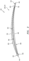
- the vane airfoil 28 of FIG. 1 extends spanwise along a span line 36 between an airfoil inner end 38 and an airfoil outer end 40, where the airfoil outer end 40 is positioned radially outboard of the airfoil inner end 38.
- the vane airfoil 28 extends longitudinally along a camber line 42 between an (e.g., forward, upstream) airfoil leading edge 44 and an (e.g., aft, downstream) airfoil trailing edge 46.
- the vane airfoil 28 extends laterally (e.g., widthwise) between an (e.g., pressure, concave) airfoil first side 48 and an (e.g., suction, convex) airfoil second side 50.
- an (e.g., pressure, concave) airfoil first side 48 and an (e.g., suction, convex) airfoil second side 50.
- each of these vane airfoil elements 44, 46, 48 and 50 extends between and to the airfoil inner end 38 and the airfoil outer end 40.
- the vane airfoil 28 has an airfoil inner end portion 52, an airfoil outer end portion 53 and an airfoil intermediate portion 54. Each of these portions 52-54 defines a respective part of the airfoil elements 44, 46, 48 and 50; see also FIG. 2 .
- the intermediate portion 54 extends spanwise between and to the inner end portion 52 and the outer end portion 53.
- the inner end portion 52 is arranged at the airfoil inner end 38, and is connected to the vane inner platform 30.
- the outer end portion 53 is arranged at the airfoil outer end 40, and is connected to the vane outer platform 31.
- the vane inner platform 30 is configured to form an inner peripheral portion of the flowpath 26.
- the vane outer platform 31 is positioned radially outboard of the vane inner platform 30.
- the vane outer platform 31 is configured to form an outer peripheral portion of the flowpath 26.
- the vane inner mount 32 is configured to attach and structurally tie the vane 20 to the inner structure 22.
- the vane outer mount 33 is configured to attach and structurally tie the vane 20 to the outer structure 24. Referring to FIG. 1 , the vane inner mount 32 is positioned radially inboard of and connected to the vane inner platform 30.
- the vane outer mount 33 is position radially outboard of and connected to the vane outer platform 31.
- the vane airfoil 28 of FIGS. 1 and 2 is configured as a multi-material (e.g., bimaterial) airfoil; e.g., a metallic-composite hybrid airfoil.
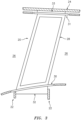
- the vane airfoil 28 of FIGS. 1 and 2 for example, includes an airfoil base section 56, an airfoil first side section 58 and an airfoil second side section 60.
- the base section 56 may be constructed from or otherwise base section material.
- An example of the base section material is metal such as, but not limited to, steel, titanium (Ti), aluminum (Al), nickel (Ni) or alloys thereof.
- the first side section 58 may be constructed from or otherwise include first side section non-metal material.
- the second side section 60 may be constructed from or otherwise include second side section non-metal material, which second side section non-metal material may be the same or different than the first side section non-metal material.
- first and the second side section non-metal materials include, but are not limited to, composite materials (e.g., materials including fiber-reinforcement within a polymer matrix, such as carbon fiber and/or fiberglass within a thermoset or thermoplastic matrix).
- the base section 56 of the vane airfoil 28 may be configured integrally with one or more or each of the other vane components 30-33.
- the vane components 28 and 30-33 of FIG. 4 are configured together as a monolithic metal body.
- the vane components 28 and 30-33 may be cast, machined, additively manufactured or otherwise formed as a single body of material.
- the present disclosure is not limited to such an exemplary monolithic metal body embodiment.
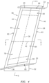
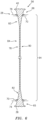
- the base section 56 may have an I-beam configuration; e.g., an I-beam cross-sectional geometry when viewed, for example, in a plane perpendicular to the span line 36.
- the base section 56 of FIGS. 4 and 5 for example, includes a leading edge segment 62, a trailing edge segment 63 and an intermediate segment 64 where the edge segments 62 and 63 represent flange portions of the I-beam configuration and the intermediate segment 64 represents a web portion of the I-beam configuration.
- the base section 56 of FIG. 4 also includes an inner end segment 65 and an outer end segment 66 which cap ends of the intermediate segment 64.
- the leading edge segment 62 extends along and at least partially (e.g., completely) defines the airfoil leading edge 44.
- the leading edge segment 62 also partially defines a (e.g., forward, upstream) first portion of the airfoil first side 48 and/or a (e.g., forward, upstream) first portion of the airfoil second side 50, where the first portions meet at the airfoil leading edge 44 and extend longitudinally towards the airfoil trailing edge 46 as well as extend spanwise between the airfoil ends 38 and 40.
- the trailing edge segment 63 extends along and at least partially (e.g., completely) defines the airfoil trailing edge 46.
- the trailing edge segment 63 also partially defines a (e.g., aft, downstream) second portion of the airfoil first side 48 and/or a (e.g., aft, downstream) second portion of the airfoil second side 50, where the second portions meet at the airfoil trailing edge 46 and extend longitudinally towards the airfoil leading edge 44 as well as extend spanwise between the airfoil ends 38 and 40.
- the intermediate segment 64 extends longitudinally between and is connected to the leading edge segment 62 and the trailing edge segment 63.
- the intermediate segment 64 extends spanwise between and is connected to the inner end segment 65 and the outer end segment 66.
- the leading edge segment 62 has a lateral width 68 that is greater than a lateral width 70 of the intermediate segment 64.
- the trailing edge segment 63 has a lateral width 72 that is greater than the lateral width 70 of the intermediate segment 64.
- the inner end segment 65 has a lateral width 74 that is greater than the lateral width 70 of the intermediate segment 64.
- the outer end segment 66 has a lateral width 76 that is greater than the lateral width 70 of the intermediate segment 64.
- the base section 56 is configured with one or more pockets 78 and 80; e.g., recesses.
- the first pocket 78 is disposed at the airfoil first side 48 (see FIG. 2 ) and projects partially into the base section 56 to the intermediate segment 64.
- the second pocket 80 is disposed at the airfoil second side 50 (see FIG. 2 ) and projects partially into the base section 56 to the intermediate segment 64.
- the intermediate segment 64 (e.g., completely) laterally separates the first pocket 78 form the second pocket 80.
- the intermediate segment 64 of FIG. 4 and, more particularly, the entire base section 56, for example, is configured as an aperture free body.
- the first pocket 78 and the second pocket 80 may thereby be (e.g., completely) discrete from one another.
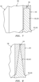
- the intermediate segment 64 of FIG. 4 includes an inner portion 82, an outer portion 83 and an intermediate portion 84. These portions 82-84 are longitudinally aligned along the camber line 42.
- the intermediation portion 84 extends spanwise between and to the inner portion 82 and the outer portion 83.
- the inner portion 82 provides a lateral width transition between the inner end segment 65 and the intermediation portion 84 of the intermediate segment 64.
- the outer portion 83 provides a lateral width transition between the outer end segment 66 and the intermediation portion 84 of the intermediate segment 64.
- FIG. 6 the inner portion 82 provides a lateral width transition between the inner end segment 65 and the intermediation portion 84 of the intermediate segment 64.
- the outer portion 83 provides a lateral width transition between the outer end segment 66 and the intermediation portion 84 of the intermediate segment 64.
- one or each portion 82, 83 may be configured to provide a stepped transition where a lateral width of the portion 82, 83 is less than a lateral width of the end segment 65, 66 and greater than a lateral width of the intermediation portion 84.
- one or each portion 82, 83 may alternatively be configured as a tapered transition where a lateral width of the portion 82, 83 (e.g., smoothly, continuously and/or otherwise) tapers down from the lateral width of the end segment 65, 66 to the lateral width of the intermediation portion 84.
- the present disclosure is not limited to including such transitions.
- the first side section 58 is seated within the first pocket 78 and connected (e.g., bonded and/or otherwise attached) to the base section 56 and its intermediate segment 64.
- the first side section 58 extends longitudinally between and longitudinally abuts the leading edge segment 62 and the trailing edge segment 63.
- the first side section 58 extends spanwise between and spanwise abuts the inner end segment 65 and the outer end segment 66.
- the first side section 58 along with the base section segments 62, 63, 65 and 66 are configured to collectively form the airfoil first side 48 and an exterior flow surface of the airfoil 28 at that first side 48.
- the base section 56 and the first side section 58 collectively form the intermediation portion 84 of the airfoil 28 at its first side 48.
- the base section 56 alone may form one or both of the end portions 52, 53 of the airfoil 28 at its first side 48.
- the second side section 60 is seated within the second pocket 80 and connected (e.g., bonded and/or otherwise attached) to the base section 56.
- the second side section 60 extends longitudinally between and longitudinally abuts the leading edge segment 62 and the trailing edge segment 63.
- the second side section 60 extends spanwise between and spanwise abuts the inner end segment 65 and the outer end segment 66.
- the second side section 60 along with the base section segments 62, 63, 65 and 66 are configured to collectively form the airfoil second side 50 and an exterior flow surface of the airfoil 28 at that second side 50.
- the base section 56 and the second side section 60 collectively form the intermediation portion 84 of the airfoil 28 at its second side 50.
- the base section 56 alone may form one or both of the end portions 52, 53 of the airfoil 28 at its second side 50.
- the base section 56 and its intermediate segment 64 (e.g., completely) separate the first side section 58 from the second side section 60.
- This separation may facilitate a relatively low complexity manufacturing process.
- the first pocket 78 may first be (e.g., completely) filled with the first non-metal material to form the first side section 58.
- the body may then be flipped over and the second pocket 80 may then be (e.g., completely) filled with the second non-metal material to form the second side section 60, or vice versa.
- the present disclosure is not limited to any particular manufacturing techniques or steps.
- each side section 58, 60 has an end-to-end length 86 along the span line 36.
- Each airfoil 28 has an end-to-end length 88 (e.g., vane height) along the span line 36.
- the side section length 86 may be less than the airfoil length 88 due to, for example, provision of the end portions 52 and 53.
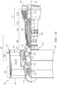
- FIG. 10 is a side cutaway illustration of a geared turbine engine 90 which may be configured with one or more (e.g., a circumferential array) of the vanes 20.
- This turbine engine 90 extends along an axial centerline 92 between an upstream airflow inlet 94 and a downstream airflow exhaust 96.
- the turbine engine 90 includes a fan section 98, a compressor section 99, a combustor section 100 and a turbine section 101.
- the compressor section 99 includes a low pressure compressor (LPC) section 99A and a high pressure compressor (HPC) section 99B.
- the turbine section 101 includes a high pressure turbine (HPT) section 101A and a low pressure turbine (LPT) section 101B.
- the engine sections 98-101B are arranged sequentially along the centerline 92 within an engine housing 104.
- This housing 104 includes an inner case 106 (e.g., a core case) and an outer case 108 (e.g., a fan case).
- the inner case 106 may house one or more of the engine sections 99A-101B; e.g., an engine core.
- the inner case 106 is configured with, includes or is part of the inner structure 22.
- the outer case 108 may house at least the fan section 98.
- the outer case 108 is configured with, includes or is part of the outer structure 24.
- Each of the engine sections 98, 99A, 99B, 101A and 101B includes a respective rotor 110-114.
- Each of these rotors 110-114 includes a plurality of rotor blades arranged circumferentially around and connected to one or more respective rotor disks.
- the rotor blades may be formed integral with or mechanically fastened, welded, brazed, adhered and/or otherwise attached to the respective rotor disk(s).
- the fan rotor 110 is connected to a gear train 116, for example, through a fan shaft 118.
- the gear train 116 and the LPC rotor 111 are connected to and driven by the LPT rotor 114 through a low speed shaft 119.
- the HPC rotor 112 is connected to and driven by the HPT rotor 113 through a high speed shaft 120.
- the shafts 118-120 are rotatably supported by a plurality of bearings 122; e.g., rolling element and/or thrust bearings.
- Each of these bearings 122 is connected to the engine housing 104 by at least one stationary structure such as, for example, an annular support strut.
- This air is directed through the fan section 98 and into a core flowpath 124 and a bypass flowpath (e.g., the flowpath 26 of FIG. 3 ).
- the core flowpath 124 extends sequentially through the engine sections 99A-101B.
- the air within the core flowpath 124 may be referred to as "core air”.
- the bypass flowpath 126 extends through a bypass duct, which bypasses the engine core.
- the air within the bypass flowpath 126 may be referred to as "bypass air”.
- the core air is compressed by the compressor rotors 111 and 112 and directed into a combustion chamber 128 of a combustor in the combustor section 100.
- Fuel is injected into the combustion chamber 128 and mixed with the compressed core air to provide a fuel-air mixture.
- This fuel air mixture is ignited and combustion products thereof flow through and sequentially cause the turbine rotors 113 and 114 to rotate.
- the rotation of the turbine rotors 113 and 114 respectively drive rotation of the compressor rotors 112 and 111 and, thus, compression of the air received from a core airflow inlet.
- the rotation of the turbine rotor 114 also drives rotation of the fan rotor 110, which propels bypass air through and out of the bypass flowpath 126.
- the propulsion of the bypass air may account for a majority of thrust generated by the turbine engine 90, e.g., more than seventy-five percent (75%) of engine thrust.
- the turbine engine 90 of the present disclosure is not limited to the foregoing exemplary thrust ratio.
- the vane 20 / an assembly including the vane 20 may be included in various turbine engines other than the one described above.
- the vane 20, for example, may be included in a geared turbine engine where a gear train connects one or more shafts to one or more rotors in a fan section, a compressor section and/or any other engine section.
- the vane 20 may be included in a turbine engine configured without a gear train.
- the vane 20 may be included in a geared or non-geared turbine engine configured with a single spool, with two spools (e.g., see FIG. 10 ), or with more than two spools.
- the turbine engine may be configured as a turbofan engine, a turbojet engine, a propfan engine, a pusher fan engine or any other type of turbine engine. The present disclosure therefore is not limited to any particular types or configurations of turbine engines.
Landscapes
- Engineering & Computer Science (AREA)
- Mechanical Engineering (AREA)
- General Engineering & Computer Science (AREA)
- Chemical & Material Sciences (AREA)
- Materials Engineering (AREA)
- Turbine Rotor Nozzle Sealing (AREA)
- Structures Of Non-Positive Displacement Pumps (AREA)
Claims (13)
- Aube (20) pour moteur à turbine à gaz, comprenant :un profil aérodynamique (28) s'étendant le long d'une ligne de cambrure (42) entre un bord d'attaque (44) et un bord de fuite (46), le profil aérodynamique (28) s'étendant le long d'une ligne d'envergure (36) entre une extrémité interne (38) et une extrémité externe (40), le profil aérodynamique (28) s'étendant latéralement entre un premier côté (48) et un second côté (50), et le profil aérodynamique (28) comprenant une section de base (56), une première section latérale (58) et une seconde section latérale (60) ;la section de base (56) définissant au moins une partie du bord de fuite (46) du profil aérodynamique (28), la section de base (56) étant latéralement entre et reliée à la première section latérale (58) et à la seconde section latérale (60), et la section de base (56) comprenant un matériau métallique ;la première section latérale (58) définissant au moins une partie du premier côté (48) du profil aérodynamique (28), et la première section latérale (58) comprenant un premier matériau non métallique ; etla seconde section latérale (60) définissant au moins une partie du second côté (50) du profil aérodynamique (28), et la seconde section latérale (60) comprenant un second matériau non métallique,caractérisé en ce quela section de base (56) comporte une première partie et une seconde partie alignées le long de la ligne de cambrure (42) ; la première partie se situe entre la seconde partie et l'une de l'extrémité interne (38) et de l'extrémité externe (40) le long de la ligne d'envergure (36) ; etla première partie présente une première épaisseur latérale,caractérisé en ce que :la seconde partie a une seconde épaisseur latérale qui est inférieure à la première épaisseur latérale ; etau moins l'une de la première section latérale (58) ou de la seconde section latérale (60) se chevauche et est reliée à la première partie et à la seconde partie.
- Aube (20) selon la revendication 1, dans laquelle la section de base (56) définit également au moins une partie du bord d'attaque (44) du profil aérodynamique (28).
- Aube (20) selon la revendication 1 ou 2, dans laquelle la première section latérale (58) est placée dans une première poche (78) dans la section de base (56) et dans laquelle, éventuellement, la seconde section latérale (60) est placée dans une seconde poche (80) dans la section de base (56).
- Aube (20) selon la revendication 1, 2 ou 3, dans laquelle la section de base (56) a une configuration de poutre en I.
- Aube (20) selon une quelconque revendication précédente, dans laquelle la section de base (56) définit la totalité du bord de fuite (46) du profil aérodynamique (28) et/ou la totalité du bord d'attaque (44) du profil aérodynamique (28).
- Aube (20) selon une quelconque revendication précédente, dans laquelle la section de base (56) sépare latéralement la première section latérale (58) de la seconde section latérale (60).
- Aube (20) selon une quelconque revendication précédente, dans laquelle :le profil aérodynamique (28) a une longueur d'envergure (88) s'étendant le long de la ligne d'envergure (36) entre l'extrémité interne (38) et l'extrémité externe (40) du profil aérodynamique (28) ; etune longueur de bout en bout (86) de la première section latérale (58) le long de la ligne d'envergure (36) est inférieure à la longueur d'envergure (88).
- Aube (20) selon une quelconque revendication précédente, dans laquelle :le profil aérodynamique (28) comporte une partie d'extrémité interne (52) au niveau de l'extrémité interne (38), une partie d'extrémité externe (53) au niveau de l'extrémité externe (40) et une partie intermédiaire (54) s'étendant le long de la ligne d'envergure (36) entre la partie d'extrémité interne (52) et la partie d'extrémité externe (53) ;au moins la section de base (56), la première section latérale (58) et la seconde section latérale (60) forment collectivement la partie intermédiaire (54) ; etau moins la section de base (56) forme au moins l'une de la partie d'extrémité interne (52) ou de la partie d'extrémité externe (53) ; et,éventuellement, ni la première section latérale (58) ni la seconde section latérale (60) ne forment au moins l'une de la partie d'extrémité interne (52) ou de la partie d'extrémité externe (53).
- Aube (20) selon une quelconque revendication précédente, dans laquelle :
la première section latérale (58) vient en butée contre la section de base (56) dans la direction d'envergure. - Aube selon la revendication 9, dans laquelle :
la seconde section latérale (60) vient en butée contre la section de base (56) dans la direction d'envergure. - Aube (20) selon une quelconque revendication précédente, comprenant également :une plate-forme interne (30) ; etune plate-forme externe (31) ;le profil aérodynamique (28) s'étendant le long de la ligne d'envergure (36) entre et étant relié à la plate-forme interne (30) et à la plate-forme externe (31).
- Aube (20) selon une quelconque revendication précédente, dans laquelle au moins l'un du premier matériau non métallique ou du second matériau non métallique comprend un matériau composite renforcé par des fibres.
- Aube (20) selon une quelconque revendication précédente, dans laquelle l'aube (20) est configurée comme une aube directrice structurelle du moteur à turbine à gaz.
Applications Claiming Priority (1)
| Application Number | Priority Date | Filing Date | Title |
|---|---|---|---|
| US16/851,911 US11795831B2 (en) | 2020-04-17 | 2020-04-17 | Multi-material vane for a gas turbine engine |
Publications (3)
| Publication Number | Publication Date |
|---|---|
| EP3896254A2 EP3896254A2 (fr) | 2021-10-20 |
| EP3896254A3 EP3896254A3 (fr) | 2021-12-22 |
| EP3896254B1 true EP3896254B1 (fr) | 2024-09-25 |
Family
ID=75581378
Family Applications (1)
| Application Number | Title | Priority Date | Filing Date |
|---|---|---|---|
| EP21168985.6A Active EP3896254B1 (fr) | 2020-04-17 | 2021-04-16 | Aube multi-matériaux pour un moteur à turbine à gaz |
Country Status (2)
| Country | Link |
|---|---|
| US (1) | US11795831B2 (fr) |
| EP (1) | EP3896254B1 (fr) |
Families Citing this family (3)
| Publication number | Priority date | Publication date | Assignee | Title |
|---|---|---|---|---|
| US12359572B2 (en) | 2023-02-20 | 2025-07-15 | General Electric Company | Turbine engine with composite airfoils |
| US12297746B2 (en) * | 2023-10-11 | 2025-05-13 | Rtx Corporation | Erosion compensated vane geometry |
| US12655851B2 (en) | 2024-11-18 | 2026-06-16 | Howden Turbo Gmbh | Centrifugal fan or compressor composite impeller with abrasion resistance |
Family Cites Families (73)
| Publication number | Priority date | Publication date | Assignee | Title |
|---|---|---|---|---|
| US3060561A (en) | 1959-07-27 | 1962-10-30 | Budd Co | Method of forming curved sandwich panels |
| US3002717A (en) | 1960-01-12 | 1961-10-03 | Pavlecka John | Airfoil structure |
| US3903578A (en) | 1972-02-28 | 1975-09-09 | United Aircraft Corp | Composite fan blade and method of construction |
| US4029838A (en) | 1975-09-24 | 1977-06-14 | The United States Of America As Represented By The Administrator Of The National Aeronautics And Space Administration | Hybrid composite laminate structures |
| US4118147A (en) | 1976-12-22 | 1978-10-03 | General Electric Company | Composite reinforcement of metallic airfoils |
| US4671470A (en) | 1985-07-15 | 1987-06-09 | Beech Aircraft Corporation | Method for fastening aircraft frame elements to sandwich skin panels covering same using woven fiber connectors |
| US4808485A (en) | 1988-02-05 | 1989-02-28 | United Technologies Corporation | Microstructurally toughened metal matrix composite article and method of making same |
| US4885212A (en) | 1988-02-05 | 1989-12-05 | United Technologies Corporation | Microstructurally toughened metal matrix composite article and method of making same |
| US4911990A (en) | 1988-02-05 | 1990-03-27 | United Technologies Corporation | Microstructurally toughened metallic article and method of making same |
| US4999256A (en) | 1988-02-05 | 1991-03-12 | United Technologies Corporation | Microstructurally toughened metal matrix composite article |
| US5079099A (en) | 1988-02-05 | 1992-01-07 | United Technologies Corporation | Microstructurally toughened metal matrix composite article and method of making same |
| US5015116A (en) | 1988-08-22 | 1991-05-14 | United Technologies Corporation | Structural joints of high dimensional stability |
| FR2688264A1 (fr) | 1992-03-04 | 1993-09-10 | Snecma | Redresseur de turbomachine a aubes ayant une face alveolee chargee en materiau composite. |
| FR2695163B1 (fr) | 1992-09-02 | 1994-10-28 | Snecma | Aube creuse pour turbomachine et son procédé de fabrication. |
| US5370831A (en) | 1992-12-18 | 1994-12-06 | United Technologies Corporation | Method of molding polymeric skins for trim products |
| US5366765A (en) | 1993-05-17 | 1994-11-22 | United Technologies Corporation | Aqueous slurry coating system for aluminide coatings |
| US5687900A (en) | 1995-03-28 | 1997-11-18 | Mcdonnell Douglas Corporation | Structural panel having a predetermined shape and an associated method for superplastically forming and diffusion bonding the structural panel |
| US5692881A (en) | 1995-06-08 | 1997-12-02 | United Technologies Corporation | Hollow metallic structure and method of manufacture |
| US5634771A (en) | 1995-09-25 | 1997-06-03 | General Electric Company | Partially-metallic blade for a gas turbine |
| JPH1054204A (ja) | 1996-05-20 | 1998-02-24 | General Electric Co <Ge> | ガスタービン用の多構成部翼 |
| US5931641A (en) | 1997-04-25 | 1999-08-03 | General Electric Company | Steam turbine blade having areas of different densities |
| US5913661A (en) | 1997-12-22 | 1999-06-22 | General Electric Company | Striated hybrid blade |
| US5947688A (en) | 1997-12-22 | 1999-09-07 | General Electric Company | Frequency tuned hybrid blade |
| US6039542A (en) | 1997-12-24 | 2000-03-21 | General Electric Company | Panel damped hybrid blade |
| US6033186A (en) | 1999-04-16 | 2000-03-07 | General Electric Company | Frequency tuned hybrid blade |
| US6287080B1 (en) | 1999-11-15 | 2001-09-11 | General Electric Company | Elastomeric formulation used in the construction of lightweight aircraft engine fan blades |
| US6364616B1 (en) | 2000-05-05 | 2002-04-02 | General Electric Company | Submerged rib hybrid blade |
| US6514046B1 (en) | 2000-09-29 | 2003-02-04 | Siemens Westinghouse Power Corporation | Ceramic composite vane with metallic substructure |
| US6743504B1 (en) | 2001-03-01 | 2004-06-01 | Rohr, Inc. | Co-cured composite structures and method of making them |
| DE50113629D1 (de) | 2001-04-04 | 2008-04-03 | Siemens Ag | Verfahren zur Herstellung einer Turbinenschaufel |
| US6846160B2 (en) * | 2001-10-12 | 2005-01-25 | Hitachi, Ltd. | Turbine bucket |
| EP1499525A1 (fr) | 2002-04-29 | 2005-01-26 | Rolls-Royce Naval Marine, Inc. | Helice |
| JP4248974B2 (ja) | 2003-09-02 | 2009-04-02 | 日東電工株式会社 | 光源装置および液晶表示装置 |
| US7104760B2 (en) | 2004-05-05 | 2006-09-12 | General Electric Company | Hybrid bucket and related method of pocket design |
| US7080805B2 (en) | 2004-05-05 | 2006-07-25 | The Boeing Company | Stiffened structures and associated methods |
| US7410342B2 (en) | 2005-05-05 | 2008-08-12 | Florida Turbine Technologies, Inc. | Airfoil support |
| GB0516036D0 (en) | 2005-08-04 | 2005-09-14 | Rolls Royce Plc | Aerofoil |
| US7240718B2 (en) | 2005-09-13 | 2007-07-10 | United Technologies Corporation | Method for casting core removal |
| US7334997B2 (en) | 2005-09-16 | 2008-02-26 | General Electric Company | Hybrid blisk |
| US7508466B2 (en) | 2005-11-14 | 2009-03-24 | Cree, Inc. | Laser diode backlighting of LC display with at least one diode generating light beam having divergence angle and with display panel having beam spreader to increase divergence |
| CN101360948B (zh) | 2005-11-15 | 2011-01-19 | 松下电器产业株式会社 | 面状照明装置和使用其的液晶显示装置 |
| US7766625B2 (en) | 2006-03-31 | 2010-08-03 | General Electric Company | Methods and apparatus for reducing stress in turbine buckets |
| US7942639B2 (en) | 2006-03-31 | 2011-05-17 | General Electric Company | Hybrid bucket dovetail pocket design for mechanical retainment |
| US7429165B2 (en) | 2006-06-14 | 2008-09-30 | General Electric Company | Hybrid blade for a steam turbine |
| US7845841B2 (en) | 2006-08-28 | 2010-12-07 | Qualcomm Mems Technologies, Inc. | Angle sweeping holographic illuminator |
| US20080072569A1 (en) | 2006-09-27 | 2008-03-27 | Thomas Ory Moniz | Guide vane and method of fabricating the same |
| US20080159856A1 (en) | 2006-12-29 | 2008-07-03 | Thomas Ory Moniz | Guide vane and method of fabricating the same |
| US7828526B2 (en) * | 2007-04-11 | 2010-11-09 | General Electric Company | Metallic blade having a composite inlay |
| US7980817B2 (en) * | 2007-04-16 | 2011-07-19 | United Technologies Corporation | Gas turbine engine vane |
| US8107035B2 (en) | 2007-04-19 | 2012-01-31 | Necsel Intellectual Property | Laser backlighting for displays |
| US8297825B2 (en) | 2008-03-19 | 2012-10-30 | Panasonic Corporation | Surface light source device |
| TWI325971B (en) | 2008-05-30 | 2010-06-11 | Au Optronics Corp | Light diffusion device, backlight module and liquid crystal display |
| US8333552B2 (en) * | 2008-06-20 | 2012-12-18 | General Electric Company | Combined acoustic absorber and heat exchanging outlet guide vanes |
| US8054404B2 (en) | 2008-08-05 | 2011-11-08 | Sharp Kabushiki Kaisha | Surface light source device |
| US20110205453A1 (en) | 2008-10-23 | 2011-08-25 | Sharp Kabushiki Kaisha | Illumination device, surface illuminant device, display device, and television receiver |
| WO2010052955A1 (fr) | 2008-11-04 | 2010-05-14 | シャープ株式会社 | Dispositif de source de lumière plan et dispositif d’affichage à cristaux liquides |
| JP5029572B2 (ja) | 2008-11-07 | 2012-09-19 | 住友電気工業株式会社 | 導光板、配線モジュールおよび電子機器 |
| DE102008058786A1 (de) | 2008-11-24 | 2010-05-27 | Rolls-Royce Deutschland Ltd & Co Kg | Hybrides Bauteil für ein Gasturbinentriebwerk |
| US8177513B2 (en) * | 2009-02-18 | 2012-05-15 | General Electric Company | Method and apparatus for a structural outlet guide vane |
| US8585368B2 (en) | 2009-04-16 | 2013-11-19 | United Technologies Corporation | Hybrid structure airfoil |
| US8083489B2 (en) | 2009-04-16 | 2011-12-27 | United Technologies Corporation | Hybrid structure fan blade |
| US7955054B2 (en) | 2009-09-21 | 2011-06-07 | Pratt & Whitney Rocketdyne, Inc. | Internally damped blade |
| GB0916758D0 (en) | 2009-09-24 | 2009-11-04 | Rolls Royce Plc | A hybrid component |
| TWM388013U (en) | 2010-02-09 | 2010-09-01 | Power Digital Communications Co Ltd | Multi-directional lighting for a backlight board |
| TWI426302B (zh) | 2010-02-12 | 2014-02-11 | Au Optronics Corp | 顯示裝置及其增光膜 |
| US20110205756A1 (en) | 2010-02-19 | 2011-08-25 | Pixtronix, Inc. | Light guides and backlight systems incorporating prismatic structures and light redirectors |
| FR2964427B1 (fr) * | 2010-09-06 | 2014-05-09 | Messier Dowty Sa | Carter de turboreacteur et turboreacteur recevant de tels carters |
| US8585268B2 (en) | 2011-10-21 | 2013-11-19 | Ergophos, Llc | Light-guide panel for display with laser backlight |
| US8998575B2 (en) | 2011-11-14 | 2015-04-07 | United Technologies Corporation | Structural stator airfoil |
| US20140010662A1 (en) | 2012-07-03 | 2014-01-09 | United Technologies Corporation | Composite airfoil with integral platform |
| US10260523B2 (en) * | 2016-04-06 | 2019-04-16 | Rolls-Royce North American Technologies Inc. | Fluid cooling system integrated with outlet guide vane |
| US10711624B2 (en) * | 2016-11-17 | 2020-07-14 | Raytheon Technologies Corporation | Airfoil with geometrically segmented coating section |
| FR3084695B1 (fr) | 2018-07-31 | 2024-10-25 | Safran Aircraft Engines | Aube composite a armature metallique et son procede de fabrication |
-
2020
- 2020-04-17 US US16/851,911 patent/US11795831B2/en active Active
-
2021
- 2021-04-16 EP EP21168985.6A patent/EP3896254B1/fr active Active
Also Published As
| Publication number | Publication date |
|---|---|
| US20210324752A1 (en) | 2021-10-21 |
| US11795831B2 (en) | 2023-10-24 |
| EP3896254A3 (fr) | 2021-12-22 |
| EP3896254A2 (fr) | 2021-10-20 |
Similar Documents
| Publication | Publication Date | Title |
|---|---|---|
| EP3896255B1 (fr) | Aube multi-matériaux pour un moteur à turbine à gaz | |
| US8177513B2 (en) | Method and apparatus for a structural outlet guide vane | |
| EP2366871B1 (fr) | Procédé et appareil pour conduit d'aube de sortie structurelle | |
| US20160053617A1 (en) | Rotors with modulus mistuned airfoils | |
| JP2008082337A (ja) | ガイドベーン及びガスタービンエンジン組立体 | |
| EP2820297B1 (fr) | Turbine d'entraînement de soufflante légère | |
| EP3896254A2 (fr) | Aube multi-matériaux pour un moteur à turbine à gaz | |
| EP3816398A1 (fr) | Profil aérodynamique ayant des gaines avec un joint à rigidité continue | |
| US20230036022A1 (en) | Rotor Blade with Frangible Spar for a Gas Turbine Engine | |
| US11499566B2 (en) | Fan blade having closed metal sheath | |
| US11401814B2 (en) | Rotor assembly with internal vanes | |
| EP3851637B1 (fr) | Ensemble rotor pour un moteur à turbine à gaz | |
| EP3851639B1 (fr) | Aube rotorique et ensemble rotor pour un moteur à turbine à gaz | |
| US11339673B2 (en) | Rotor assembly with internal vanes | |
| US11371351B2 (en) | Multi-disk bladed rotor assembly for rotational equipment | |
| US11286781B2 (en) | Multi-disk bladed rotor assembly for rotational equipment | |
| JP5647426B2 (ja) | 構造出口案内翼のための方法及び装置 | |
| CA2697292C (fr) | Procede et appareil pour aube directrice d'event de decharge structurel | |
| US20210222567A1 (en) | Rotor blade and method for forming a rotor blade | |
| US12196129B2 (en) | Compressor with counter-rotating blade rows |
Legal Events
| Date | Code | Title | Description |
|---|---|---|---|
| PUAI | Public reference made under article 153(3) epc to a published international application that has entered the european phase |
Free format text: ORIGINAL CODE: 0009012 |
|
| STAA | Information on the status of an ep patent application or granted ep patent |
Free format text: STATUS: THE APPLICATION HAS BEEN PUBLISHED |
|
| AK | Designated contracting states |
Kind code of ref document: A2 Designated state(s): AL AT BE BG CH CY CZ DE DK EE ES FI FR GB GR HR HU IE IS IT LI LT LU LV MC MK MT NL NO PL PT RO RS SE SI SK SM TR |
|
| PUAL | Search report despatched |
Free format text: ORIGINAL CODE: 0009013 |
|
| AK | Designated contracting states |
Kind code of ref document: A3 Designated state(s): AL AT BE BG CH CY CZ DE DK EE ES FI FR GB GR HR HU IE IS IT LI LT LU LV MC MK MT NL NO PL PT RO RS SE SI SK SM TR |
|
| RIC1 | Information provided on ipc code assigned before grant |
Ipc: F01D 9/04 20060101ALI20211118BHEP Ipc: F01D 5/28 20060101ALI20211118BHEP Ipc: F01D 5/14 20060101AFI20211118BHEP |
|
| STAA | Information on the status of an ep patent application or granted ep patent |
Free format text: STATUS: REQUEST FOR EXAMINATION WAS MADE |
|
| 17P | Request for examination filed |
Effective date: 20220622 |
|
| RBV | Designated contracting states (corrected) |
Designated state(s): AL AT BE BG CH CY CZ DE DK EE ES FI FR GB GR HR HU IE IS IT LI LT LU LV MC MK MT NL NO PL PT RO RS SE SI SK SM TR |
|
| RAP3 | Party data changed (applicant data changed or rights of an application transferred) |
Owner name: RTX CORPORATION |
|
| GRAP | Despatch of communication of intention to grant a patent |
Free format text: ORIGINAL CODE: EPIDOSNIGR1 |
|
| STAA | Information on the status of an ep patent application or granted ep patent |
Free format text: STATUS: GRANT OF PATENT IS INTENDED |
|
| INTG | Intention to grant announced |
Effective date: 20240425 |
|
| GRAS | Grant fee paid |
Free format text: ORIGINAL CODE: EPIDOSNIGR3 |
|
| GRAA | (expected) grant |
Free format text: ORIGINAL CODE: 0009210 |
|
| STAA | Information on the status of an ep patent application or granted ep patent |
Free format text: STATUS: THE PATENT HAS BEEN GRANTED |
|
| AK | Designated contracting states |
Kind code of ref document: B1 Designated state(s): AL AT BE BG CH CY CZ DE DK EE ES FI FR GB GR HR HU IE IS IT LI LT LU LV MC MK MT NL NO PL PT RO RS SE SI SK SM TR |
|
| REG | Reference to a national code |
Ref country code: GB Ref legal event code: FG4D |
|
| REG | Reference to a national code |
Ref country code: CH Ref legal event code: EP |
|
| REG | Reference to a national code |
Ref country code: DE Ref legal event code: R096 Ref document number: 602021019165 Country of ref document: DE |
|
| REG | Reference to a national code |
Ref country code: IE Ref legal event code: FG4D |
|
| REG | Reference to a national code |
Ref country code: LT Ref legal event code: MG9D |
|
| PG25 | Lapsed in a contracting state [announced via postgrant information from national office to epo] |
Ref country code: NO Free format text: LAPSE BECAUSE OF FAILURE TO SUBMIT A TRANSLATION OF THE DESCRIPTION OR TO PAY THE FEE WITHIN THE PRESCRIBED TIME-LIMIT Effective date: 20241225 |
|
| PG25 | Lapsed in a contracting state [announced via postgrant information from national office to epo] |
Ref country code: GR Free format text: LAPSE BECAUSE OF FAILURE TO SUBMIT A TRANSLATION OF THE DESCRIPTION OR TO PAY THE FEE WITHIN THE PRESCRIBED TIME-LIMIT Effective date: 20241226 Ref country code: FI Free format text: LAPSE BECAUSE OF FAILURE TO SUBMIT A TRANSLATION OF THE DESCRIPTION OR TO PAY THE FEE WITHIN THE PRESCRIBED TIME-LIMIT Effective date: 20240925 |
|
| PG25 | Lapsed in a contracting state [announced via postgrant information from national office to epo] |
Ref country code: BG Free format text: LAPSE BECAUSE OF FAILURE TO SUBMIT A TRANSLATION OF THE DESCRIPTION OR TO PAY THE FEE WITHIN THE PRESCRIBED TIME-LIMIT Effective date: 20240925 |
|
| PG25 | Lapsed in a contracting state [announced via postgrant information from national office to epo] |
Ref country code: LV Free format text: LAPSE BECAUSE OF FAILURE TO SUBMIT A TRANSLATION OF THE DESCRIPTION OR TO PAY THE FEE WITHIN THE PRESCRIBED TIME-LIMIT Effective date: 20240925 |
|
| PG25 | Lapsed in a contracting state [announced via postgrant information from national office to epo] |
Ref country code: RS Free format text: LAPSE BECAUSE OF FAILURE TO SUBMIT A TRANSLATION OF THE DESCRIPTION OR TO PAY THE FEE WITHIN THE PRESCRIBED TIME-LIMIT Effective date: 20241225 |
|
| REG | Reference to a national code |
Ref country code: NL Ref legal event code: MP Effective date: 20240925 |
|
| PG25 | Lapsed in a contracting state [announced via postgrant information from national office to epo] |
Ref country code: RS Free format text: LAPSE BECAUSE OF FAILURE TO SUBMIT A TRANSLATION OF THE DESCRIPTION OR TO PAY THE FEE WITHIN THE PRESCRIBED TIME-LIMIT Effective date: 20241225 Ref country code: NO Free format text: LAPSE BECAUSE OF FAILURE TO SUBMIT A TRANSLATION OF THE DESCRIPTION OR TO PAY THE FEE WITHIN THE PRESCRIBED TIME-LIMIT Effective date: 20241225 Ref country code: LV Free format text: LAPSE BECAUSE OF FAILURE TO SUBMIT A TRANSLATION OF THE DESCRIPTION OR TO PAY THE FEE WITHIN THE PRESCRIBED TIME-LIMIT Effective date: 20240925 Ref country code: GR Free format text: LAPSE BECAUSE OF FAILURE TO SUBMIT A TRANSLATION OF THE DESCRIPTION OR TO PAY THE FEE WITHIN THE PRESCRIBED TIME-LIMIT Effective date: 20241226 Ref country code: FI Free format text: LAPSE BECAUSE OF FAILURE TO SUBMIT A TRANSLATION OF THE DESCRIPTION OR TO PAY THE FEE WITHIN THE PRESCRIBED TIME-LIMIT Effective date: 20240925 Ref country code: BG Free format text: LAPSE BECAUSE OF FAILURE TO SUBMIT A TRANSLATION OF THE DESCRIPTION OR TO PAY THE FEE WITHIN THE PRESCRIBED TIME-LIMIT Effective date: 20240925 |
|
| REG | Reference to a national code |
Ref country code: AT Ref legal event code: MK05 Ref document number: 1726777 Country of ref document: AT Kind code of ref document: T Effective date: 20240925 |
|
| PG25 | Lapsed in a contracting state [announced via postgrant information from national office to epo] |
Ref country code: NL Free format text: LAPSE BECAUSE OF FAILURE TO SUBMIT A TRANSLATION OF THE DESCRIPTION OR TO PAY THE FEE WITHIN THE PRESCRIBED TIME-LIMIT Effective date: 20240925 |
|
| PG25 | Lapsed in a contracting state [announced via postgrant information from national office to epo] |
Ref country code: IS Free format text: LAPSE BECAUSE OF FAILURE TO SUBMIT A TRANSLATION OF THE DESCRIPTION OR TO PAY THE FEE WITHIN THE PRESCRIBED TIME-LIMIT Effective date: 20250125 Ref country code: PT Free format text: LAPSE BECAUSE OF FAILURE TO SUBMIT A TRANSLATION OF THE DESCRIPTION OR TO PAY THE FEE WITHIN THE PRESCRIBED TIME-LIMIT Effective date: 20250127 |
|
| PG25 | Lapsed in a contracting state [announced via postgrant information from national office to epo] |
Ref country code: RO Free format text: LAPSE BECAUSE OF FAILURE TO SUBMIT A TRANSLATION OF THE DESCRIPTION OR TO PAY THE FEE WITHIN THE PRESCRIBED TIME-LIMIT Effective date: 20240925 Ref country code: SM Free format text: LAPSE BECAUSE OF FAILURE TO SUBMIT A TRANSLATION OF THE DESCRIPTION OR TO PAY THE FEE WITHIN THE PRESCRIBED TIME-LIMIT Effective date: 20240925 |
|
| PG25 | Lapsed in a contracting state [announced via postgrant information from national office to epo] |
Ref country code: ES Free format text: LAPSE BECAUSE OF FAILURE TO SUBMIT A TRANSLATION OF THE DESCRIPTION OR TO PAY THE FEE WITHIN THE PRESCRIBED TIME-LIMIT Effective date: 20240925 |
|
| PG25 | Lapsed in a contracting state [announced via postgrant information from national office to epo] |
Ref country code: EE Free format text: LAPSE BECAUSE OF FAILURE TO SUBMIT A TRANSLATION OF THE DESCRIPTION OR TO PAY THE FEE WITHIN THE PRESCRIBED TIME-LIMIT Effective date: 20240925 Ref country code: AT Free format text: LAPSE BECAUSE OF FAILURE TO SUBMIT A TRANSLATION OF THE DESCRIPTION OR TO PAY THE FEE WITHIN THE PRESCRIBED TIME-LIMIT Effective date: 20240925 |
|
| PG25 | Lapsed in a contracting state [announced via postgrant information from national office to epo] |
Ref country code: PL Free format text: LAPSE BECAUSE OF FAILURE TO SUBMIT A TRANSLATION OF THE DESCRIPTION OR TO PAY THE FEE WITHIN THE PRESCRIBED TIME-LIMIT Effective date: 20240925 Ref country code: CZ Free format text: LAPSE BECAUSE OF FAILURE TO SUBMIT A TRANSLATION OF THE DESCRIPTION OR TO PAY THE FEE WITHIN THE PRESCRIBED TIME-LIMIT Effective date: 20240925 |
|
| PG25 | Lapsed in a contracting state [announced via postgrant information from national office to epo] |
Ref country code: IT Free format text: LAPSE BECAUSE OF FAILURE TO SUBMIT A TRANSLATION OF THE DESCRIPTION OR TO PAY THE FEE WITHIN THE PRESCRIBED TIME-LIMIT Effective date: 20240925 Ref country code: SK Free format text: LAPSE BECAUSE OF FAILURE TO SUBMIT A TRANSLATION OF THE DESCRIPTION OR TO PAY THE FEE WITHIN THE PRESCRIBED TIME-LIMIT Effective date: 20240925 |
|
| REG | Reference to a national code |
Ref country code: DE Ref legal event code: R097 Ref document number: 602021019165 Country of ref document: DE |
|
| PG25 | Lapsed in a contracting state [announced via postgrant information from national office to epo] |
Ref country code: DK Free format text: LAPSE BECAUSE OF FAILURE TO SUBMIT A TRANSLATION OF THE DESCRIPTION OR TO PAY THE FEE WITHIN THE PRESCRIBED TIME-LIMIT Effective date: 20240925 |
|
| PLBE | No opposition filed within time limit |
Free format text: ORIGINAL CODE: 0009261 |
|
| STAA | Information on the status of an ep patent application or granted ep patent |
Free format text: STATUS: NO OPPOSITION FILED WITHIN TIME LIMIT |
|
| 26N | No opposition filed |
Effective date: 20250626 |
|
| PG25 | Lapsed in a contracting state [announced via postgrant information from national office to epo] |
Ref country code: SE Free format text: LAPSE BECAUSE OF FAILURE TO SUBMIT A TRANSLATION OF THE DESCRIPTION OR TO PAY THE FEE WITHIN THE PRESCRIBED TIME-LIMIT Effective date: 20240925 |
|
| REG | Reference to a national code |
Ref country code: CH Ref legal event code: H13 Free format text: ST27 STATUS EVENT CODE: U-0-0-H10-H13 (AS PROVIDED BY THE NATIONAL OFFICE) Effective date: 20251125 |
|
| PG25 | Lapsed in a contracting state [announced via postgrant information from national office to epo] |
Ref country code: LU Free format text: LAPSE BECAUSE OF NON-PAYMENT OF DUE FEES Effective date: 20250416 |
|
| PG25 | Lapsed in a contracting state [announced via postgrant information from national office to epo] |
Ref country code: MC Free format text: LAPSE BECAUSE OF FAILURE TO SUBMIT A TRANSLATION OF THE DESCRIPTION OR TO PAY THE FEE WITHIN THE PRESCRIBED TIME-LIMIT Effective date: 20240925 |
|
| REG | Reference to a national code |
Ref country code: BE Ref legal event code: MM Effective date: 20250430 |
|
| PG25 | Lapsed in a contracting state [announced via postgrant information from national office to epo] |
Ref country code: HR Free format text: LAPSE BECAUSE OF FAILURE TO SUBMIT A TRANSLATION OF THE DESCRIPTION OR TO PAY THE FEE WITHIN THE PRESCRIBED TIME-LIMIT Effective date: 20240925 |
|
| PG25 | Lapsed in a contracting state [announced via postgrant information from national office to epo] |
Ref country code: BE Free format text: LAPSE BECAUSE OF NON-PAYMENT OF DUE FEES Effective date: 20250430 |
|
| PG25 | Lapsed in a contracting state [announced via postgrant information from national office to epo] |
Ref country code: CH Free format text: LAPSE BECAUSE OF NON-PAYMENT OF DUE FEES Effective date: 20250430 |
|
| PGFP | Annual fee paid to national office [announced via postgrant information from national office to epo] |
Ref country code: GB Payment date: 20260319 Year of fee payment: 6 |
|
| PG25 | Lapsed in a contracting state [announced via postgrant information from national office to epo] |
Ref country code: IE Free format text: LAPSE BECAUSE OF NON-PAYMENT OF DUE FEES Effective date: 20250416 |
|
| PGFP | Annual fee paid to national office [announced via postgrant information from national office to epo] |
Ref country code: FR Payment date: 20260320 Year of fee payment: 6 |
|
| PG25 | Lapsed in a contracting state [announced via postgrant information from national office to epo] |
Ref country code: CY Free format text: LAPSE BECAUSE OF FAILURE TO SUBMIT A TRANSLATION OF THE DESCRIPTION OR TO PAY THE FEE WITHIN THE PRESCRIBED TIME-LIMIT Effective date: 20240925 |
|
| PG25 | Lapsed in a contracting state [announced via postgrant information from national office to epo] |
Ref country code: LT Free format text: LAPSE BECAUSE OF FAILURE TO SUBMIT A TRANSLATION OF THE DESCRIPTION OR TO PAY THE FEE WITHIN THE PRESCRIBED TIME-LIMIT Effective date: 20240925 |
|
| PGFP | Annual fee paid to national office [announced via postgrant information from national office to epo] |
Ref country code: DE Payment date: 20260319 Year of fee payment: 6 |