EP3896401A1 - Brillouin- und rayleigh-verteilter sensor - Google Patents
Brillouin- und rayleigh-verteilter sensor Download PDFInfo
- Publication number
- EP3896401A1 EP3896401A1 EP21169692.7A EP21169692A EP3896401A1 EP 3896401 A1 EP3896401 A1 EP 3896401A1 EP 21169692 A EP21169692 A EP 21169692A EP 3896401 A1 EP3896401 A1 EP 3896401A1
- Authority
- EP
- European Patent Office
- Prior art keywords
- laser beam
- brillouin
- dut
- trace
- rayleigh
- Prior art date
- Legal status (The legal status is an assumption and is not a legal conclusion. Google has not performed a legal analysis and makes no representation as to the accuracy of the status listed.)
- Granted
Links
Images


Classifications
-
- G—PHYSICS
- G01—MEASURING; TESTING
- G01M—TESTING STATIC OR DYNAMIC BALANCE OF MACHINES OR STRUCTURES; TESTING OF STRUCTURES OR APPARATUS, NOT OTHERWISE PROVIDED FOR
- G01M11/00—Testing of optical apparatus; Testing structures by optical methods not otherwise provided for
- G01M11/30—Testing of optical devices, constituted by fibre optics or optical waveguides
- G01M11/31—Testing of optical devices, constituted by fibre optics or optical waveguides with a light emitter and a light receiver being disposed at the same side of a fibre or waveguide end-face, e.g. reflectometers
- G01M11/3181—Reflectometers dealing with polarisation
-
- G—PHYSICS
- G01—MEASURING; TESTING
- G01D—MEASURING NOT SPECIALLY ADAPTED FOR A SPECIFIC VARIABLE; ARRANGEMENTS FOR MEASURING TWO OR MORE VARIABLES NOT COVERED IN A SINGLE OTHER SUBCLASS; TARIFF METERING APPARATUS; MEASURING OR TESTING NOT OTHERWISE PROVIDED FOR
- G01D5/00—Mechanical means for transferring the output of a sensing member; Means for converting the output of a sensing member to another variable where the form or nature of the sensing member does not constrain the means for converting; Transducers not specially adapted for a specific variable
- G01D5/26—Mechanical means for transferring the output of a sensing member; Means for converting the output of a sensing member to another variable where the form or nature of the sensing member does not constrain the means for converting; Transducers not specially adapted for a specific variable characterised by optical transfer means, i.e. using infrared, visible, or ultraviolet light
- G01D5/32—Mechanical means for transferring the output of a sensing member; Means for converting the output of a sensing member to another variable where the form or nature of the sensing member does not constrain the means for converting; Transducers not specially adapted for a specific variable characterised by optical transfer means, i.e. using infrared, visible, or ultraviolet light with attenuation or whole or partial obturation of beams of light
- G01D5/34—Mechanical means for transferring the output of a sensing member; Means for converting the output of a sensing member to another variable where the form or nature of the sensing member does not constrain the means for converting; Transducers not specially adapted for a specific variable characterised by optical transfer means, i.e. using infrared, visible, or ultraviolet light with attenuation or whole or partial obturation of beams of light the beams of light being detected by photocells
- G01D5/353—Mechanical means for transferring the output of a sensing member; Means for converting the output of a sensing member to another variable where the form or nature of the sensing member does not constrain the means for converting; Transducers not specially adapted for a specific variable characterised by optical transfer means, i.e. using infrared, visible, or ultraviolet light with attenuation or whole or partial obturation of beams of light the beams of light being detected by photocells influencing the transmission properties of an optical fibre
- G01D5/35338—Mechanical means for transferring the output of a sensing member; Means for converting the output of a sensing member to another variable where the form or nature of the sensing member does not constrain the means for converting; Transducers not specially adapted for a specific variable characterised by optical transfer means, i.e. using infrared, visible, or ultraviolet light with attenuation or whole or partial obturation of beams of light the beams of light being detected by photocells influencing the transmission properties of an optical fibre using other arrangements than interferometer arrangements
- G01D5/35354—Sensor working in reflection
- G01D5/35358—Sensor working in reflection using backscattering to detect the measured quantity
- G01D5/35361—Sensor working in reflection using backscattering to detect the measured quantity using elastic backscattering to detect the measured quantity, e.g. using Rayleigh backscattering
-
- G—PHYSICS
- G01—MEASURING; TESTING
- G01D—MEASURING NOT SPECIALLY ADAPTED FOR A SPECIFIC VARIABLE; ARRANGEMENTS FOR MEASURING TWO OR MORE VARIABLES NOT COVERED IN A SINGLE OTHER SUBCLASS; TARIFF METERING APPARATUS; MEASURING OR TESTING NOT OTHERWISE PROVIDED FOR
- G01D5/00—Mechanical means for transferring the output of a sensing member; Means for converting the output of a sensing member to another variable where the form or nature of the sensing member does not constrain the means for converting; Transducers not specially adapted for a specific variable
- G01D5/26—Mechanical means for transferring the output of a sensing member; Means for converting the output of a sensing member to another variable where the form or nature of the sensing member does not constrain the means for converting; Transducers not specially adapted for a specific variable characterised by optical transfer means, i.e. using infrared, visible, or ultraviolet light
- G01D5/32—Mechanical means for transferring the output of a sensing member; Means for converting the output of a sensing member to another variable where the form or nature of the sensing member does not constrain the means for converting; Transducers not specially adapted for a specific variable characterised by optical transfer means, i.e. using infrared, visible, or ultraviolet light with attenuation or whole or partial obturation of beams of light
- G01D5/34—Mechanical means for transferring the output of a sensing member; Means for converting the output of a sensing member to another variable where the form or nature of the sensing member does not constrain the means for converting; Transducers not specially adapted for a specific variable characterised by optical transfer means, i.e. using infrared, visible, or ultraviolet light with attenuation or whole or partial obturation of beams of light the beams of light being detected by photocells
- G01D5/353—Mechanical means for transferring the output of a sensing member; Means for converting the output of a sensing member to another variable where the form or nature of the sensing member does not constrain the means for converting; Transducers not specially adapted for a specific variable characterised by optical transfer means, i.e. using infrared, visible, or ultraviolet light with attenuation or whole or partial obturation of beams of light the beams of light being detected by photocells influencing the transmission properties of an optical fibre
- G01D5/35338—Mechanical means for transferring the output of a sensing member; Means for converting the output of a sensing member to another variable where the form or nature of the sensing member does not constrain the means for converting; Transducers not specially adapted for a specific variable characterised by optical transfer means, i.e. using infrared, visible, or ultraviolet light with attenuation or whole or partial obturation of beams of light the beams of light being detected by photocells influencing the transmission properties of an optical fibre using other arrangements than interferometer arrangements
- G01D5/35354—Sensor working in reflection
- G01D5/35358—Sensor working in reflection using backscattering to detect the measured quantity
- G01D5/35364—Sensor working in reflection using backscattering to detect the measured quantity using inelastic backscattering to detect the measured quantity, e.g. using Brillouin or Raman backscattering
-
- G—PHYSICS
- G01—MEASURING; TESTING
- G01K—MEASURING TEMPERATURE; MEASURING QUANTITY OF HEAT; THERMALLY-SENSITIVE ELEMENTS NOT OTHERWISE PROVIDED FOR
- G01K11/00—Measuring temperature based upon physical or chemical changes not covered by groups G01K3/00, G01K5/00, G01K7/00 or G01K9/00
- G01K11/32—Measuring temperature based upon physical or chemical changes not covered by groups G01K3/00, G01K5/00, G01K7/00 or G01K9/00 using changes in transmittance, scattering or luminescence in optical fibres
- G01K11/322—Measuring temperature based upon physical or chemical changes not covered by groups G01K3/00, G01K5/00, G01K7/00 or G01K9/00 using changes in transmittance, scattering or luminescence in optical fibres using Brillouin scattering
-
- G—PHYSICS
- G01—MEASURING; TESTING
- G01M—TESTING STATIC OR DYNAMIC BALANCE OF MACHINES OR STRUCTURES; TESTING OF STRUCTURES OR APPARATUS, NOT OTHERWISE PROVIDED FOR
- G01M11/00—Testing of optical apparatus; Testing structures by optical methods not otherwise provided for
- G01M11/30—Testing of optical devices, constituted by fibre optics or optical waveguides
- G01M11/31—Testing of optical devices, constituted by fibre optics or optical waveguides with a light emitter and a light receiver being disposed at the same side of a fibre or waveguide end-face, e.g. reflectometers
- G01M11/3109—Reflectometers detecting the back-scattered light in the time-domain, e.g. OTDR
- G01M11/3127—Reflectometers detecting the back-scattered light in the time-domain, e.g. OTDR using multiple or wavelength variable input source
-
- G—PHYSICS
- G01—MEASURING; TESTING
- G01M—TESTING STATIC OR DYNAMIC BALANCE OF MACHINES OR STRUCTURES; TESTING OF STRUCTURES OR APPARATUS, NOT OTHERWISE PROVIDED FOR
- G01M11/00—Testing of optical apparatus; Testing structures by optical methods not otherwise provided for
- G01M11/30—Testing of optical devices, constituted by fibre optics or optical waveguides
- G01M11/31—Testing of optical devices, constituted by fibre optics or optical waveguides with a light emitter and a light receiver being disposed at the same side of a fibre or waveguide end-face, e.g. reflectometers
- G01M11/3172—Reflectometers detecting the back-scattered light in the frequency-domain, e.g. OFDR, FMCW, heterodyne detection
Definitions
- loss mechanisms of light transmission may include light absorption and scattering.
- absorption light may be absorbed in optical fiber material as the energy of the light is converted to heat.
- scattering light energy may be dispersed in a variety of directions as the light travels through an optical fiber, with some of the light energy being returned down the core of the optical fiber.
- Brillouin scattering occurs when light passing through a transparent medium interacts with that medium's periodic spatial and temporal variations producing that medium's refractive index.
- Brillouin scattering which is dependent on environmental variables such as strain and temperature, may be used to sense mechanical strain and temperature in optical fibers.
- Rayleigh scattering pertains to the elastic scattering of light or other electromagnetic radiation by particles. Rayleigh scattering may be used to identify anomalies in transmission of a signal along an optical fiber.
- a Brillouin and Rayleigh distributed sensor comprising: a first laser source to emit a first laser beam; a second laser source to emit a second laser beam; a photodiode to acquire a beat frequency between the first laser beam and the second laser beam, wherein the beat frequency is used to maintain a predetermined offset frequency shift between the first laser beam and the second laser beam, wherein the predetermined offset frequency shift is relative to a predetermined frequency of either the first laser beam or the second laser beam; a modulator to modulate the first laser beam, wherein the modulated first laser beam is to be injected into a device under test (DUT); and a coherent receiver to acquire a backscattered signal from the DUT, wherein the backscattered signal results from the modulated first laser beam injected into the DUT, and wherein the coherent receiver is to use the second laser beam as a local oscillator to determine Brillouin and Rayleigh traces with respect to the DUT based on the predetermined offset frequency shift between the first
- the predetermined offset frequency shift for determination of the Brillouin trace may be approximately 10.8 GHz or may be selected from a range of approximately 10.0 GHz to approximately 13.0 GHz.
- the predetermined offset frequency shift for determination of the Rayleigh trace may be selected from a range of approximately 100.0 KHz to approximately 1.0 GHz.
- the DUT may be an optical fiber.
- the sensor may further comprise a polarization beam splitter (PBS) of the coherent receiver to receive the backscattered signal, and divide the backscattered signal into two different polarization states, wherein a divided portion of the backscattered signal corresponding to a first polar state is to be mixed with the second laser beam at the first polar state, and a divided portion of the backscattered single corresponding to a second polar state is to be mixed with the second laser beam at the second polar state to determine the Brillouin and Rayleigh traces with respect to the DUT.
- PBS polarization beam splitter
- a method for Brillouin trace and Rayleigh trace determination comprising: maintaining a predetermined offset frequency shift between a first laser beam and a second laser beam, wherein the predetermined offset frequency shift is relative to a predetermined frequency of either the first laser beam or the second laser beam; modulating the first laser beam, wherein the modulated first laser beam is to be injected into a device under test (DUT); acquiring a backscattered signal from the DUT, wherein the backscattered signal results from the modulated first laser beam injected into the DUT, and wherein the second laser beam is to be used as a local oscillator; and determining, based on the acquired backscattered signal from the DUT, a Brillouin trace for the DUT.
- DUT device under test
- the method may further comprise repeating the acquisition of the backscattered signal from the DUT for a plurality of frequency shifts; sampling, based on the repeated acquisitions corresponding to the plurality of frequency shifts and the acquisition of the backscattered signal from the DUT, a distributed Brillouin spectra; and determining, based on the sampling of the distributed Brillouin spectra, a resonant Brillouin frequency shift along the DUT.
- the method may further comprise determining, based on the sampling of the distributed Brillouin spectra, integrated Brillouin power by performing an integration operation with respect to the resonant Brillouin frequency shift.
- the method may further comprise scanning the first laser beam and the second laser beam over a wavelength range with a different predetermined offset frequency shift between the two laser beams; further modulating the first laser beam associated with the different predetermined offset frequency shift, wherein the further modulated first laser beam is to be injected into the DUT; further acquiring a further backscattered signal from the DUT, wherein the further backscattered signal is based on the further modulated first laser beam injected into the DUT, and wherein the second laser beam is to be used as the local oscillator; and determining, based on the further acquired backscattered signal from the DUT, a Rayleigh trace for the DUT.
- the method may further comprise scanning the first laser beam and the second laser beam over a wavelength range with a different predetermined offset frequency shift between the two laser beams; further modulating the first laser beam associated with the different predetermined offset frequency shift, wherein the further modulated first laser beam is to be injected into the DUT; further acquiring a further backscattered signal from the DUT, wherein the further backscattered signal results from the further modulated first laser beam injected into the DUT, and wherein the second laser beam is to be used as the local oscillator; determining, based on the further acquired backscattered signal from the DUT, a Rayleigh trace for the DUT, wherein the Rayleigh trace represents Rayleigh power versus time or a distance along the DUT; and determining, based on the integrated Brillouin power, the Rayleigh power, and the resonant Brillouin frequency shift along the DUT, temperature and strain associated with the DUT.
- the DUT may be an optical fiber.
- the predetermined offset frequency shift for determination of the Brillouin trace may be approximately 10.8 GHz or may be selected from a range of approximately 10.0 GHz to approximately 13.0 GHz.
- a method for Brillouin trace and Rayleigh trace determination comprising: scanning a first laser beam and a second laser beam over a wavelength range with a predetermined offset frequency shift between the two laser beams, wherein the predetermined offset frequency shift is relative to a predetermined frequency of either the first laser beam or the second laser beam; modulating the first laser beam, wherein the modulated first laser beam is to be injected into a device under test (DUT); acquiring a backscattered signal from the DUT, wherein the backscattered signal results from the modulated first laser beam injected into the DUT, and wherein the second laser beam is to be used as a local oscillator; and determining, based on the acquired backscattered signal from the DUT, a Rayleigh trace for the DUT.
- DUT device under test
- the method may further comprise repeating the acquisition of the backscattered signal from the DUT for the predetermined offset frequency shift; and averaging, during scanning of the first laser beam and the second laser beam over the wavelength range with the predetermined offset frequency shift between the two laser beams, the repeated acquisitions of the backscattered signal from the DUT for the predetermined offset frequency shift to reduce coherent fading noises.
- the predetermined offset frequency shift may be selected from a range of approximately 100.0 KHz to approximately 1.0 GHz.
- the DUT may be an optical fiber.
- the method may further comprise maintaining a different predetermined offset frequency shift between the first laser beam and the second laser beam; further modulating the first laser beam associated with the different predetermined offset frequency shift, wherein the further modulated first laser beam is to be injected into the DUT; further acquiring a further backscattered signal from the DUT, wherein the further backscattered signal is based on the further modulated first laser beam injected into the DUT, and wherein the second laser beam is to be used as the local oscillator; and determining, based on the further acquired backscattered signal from the DUT, a Brillouin trace for the DUT.
- the method may further comprise determining, based on the Brillouin trace, Brillouin power associated with the DUT; normalizing the Brillouin power with respect to the Rayleigh power to remove power variations associated with the DUT; and determining, based on the normalized Brillouin power and a resonant Brillouin frequency shift along the DUT, temperature and strain associated with the DUT.
- the terms “a” and “an” are intended to denote at least one of a particular element.
- the term “includes” means includes but not limited to, the term “including” means including but not limited to.
- the term “based on” means based at least in part on.
- a Brillouin and Rayleigh distributed sensor may include a pair of tunable laser sources and a semiconductor optical amplifier (SOA). By tuning the laser sources to include a predetermined offset frequency shift, the sensor may be used to determine both Brillouin and Rayleigh traces for an optical fiber.
- the Brillouin and Rayleigh distributed sensor may be applied to both an optical time-domain reflectometer (OTDR) and a Brillouin OTDR (B-OTDR).
- OTDR optical time-domain reflectometer
- B-OTDR Brillouin OTDR
- the Brillouin and Rayleigh distributed sensor may provide for Brillouin and Rayleigh coherent reflectometry.
- An optical amplifier may amplify an optical signal directly, without the need to first convert the optical signal to an electrical signal.
- An SOA is a type of OA based on a semiconductor gain medium. The SOA may provide for high optical gain with respect to an optical signal over a wide wavelength range.
- An optical time-domain reflectometer is an optoelectronic instrument used to characterize an optical fiber.
- the OTDR may inject a series of optical pulses into an optical fiber under test. Based on the injected optical pulses, the OTDR may extract, from the same end of the optical fiber in which the optical pulses are injected, light that is scattered or reflected back from points along the optical fiber.
- the scattered or reflected light that is gathered back may be used to characterize the optical fiber.
- the scattered or reflected light that is gathered back may be used to detect, locate, and measure events at any location of the optical fiber.
- the events may include faults at any location of the optical fiber.
- Other types of features that may be measured by the OTDR include attenuation uniformity and attenuation rate, segment length, and location and insertion loss of connectors and splices.
- a B-OTDR may be described as a fiber optic strain and temperature distributed sensing system which can measure strain and temperature along different regions of an optical fiber.
- coherent OTDR methods typically use a single narrow laser beam and a frequency shifter in the form of an Acousto Optic Modulator (AOM) or an Electro Optic Modulator (EOM) to create an heterodyne beat frequency.
- AOM Acousto Optic Modulator
- EOM Electro Optic Modulator
- An AOM may use the acousto-optic effect to diffract and shift the frequency of light using sound waves.
- An EOM may include a signal-controlled element exhibiting the electro-optic effect, where the signal-controlled element is used to modulate a beam of light.
- the shifted laser beam when a frequency scan is applied, the shifted laser beam directly follows the single laser beam, maintaining a constant beat frequency.
- coherent OTDR techniques that utilize a single narrow laser beam and a frequency shifter include drawbacks, which add complexity to B-OTDR implementations.
- the AOM cannot produce a frequency shift matching the Brillouin frequency shift of approximately 10.8 GHz.
- the EOM output comports many lines, the fundamental, sidebands, and harmonics, which can be minimized, but still generate undesirable signals and Brillouin interactions.
- the AOM and the EOM may include from 2 dB to 5 dB insertion loss with respect to insertion of the AOM or EOM at the laser source.
- the Brillouin and Rayleigh distributed sensor may provide for both OTDR and B-OTDR implementations. Further, the Brillouin and Rayleigh distributed sensor may provide for both Brillouin and Rayleigh trace determination with respect to an optical fiber.
- a controlled frequency shift between two laser beams may be maintained for the Brillouin and Rayleigh distributed sensor.
- the range of the offset frequency shift for the Brillouin trace determination may include frequencies between approximately 10.0 GHz to approximately 13 GHz.
- the two laser beams may be set with an approximately 10.8 GHz offset frequency shift.
- a first laser beam of the two laser beams may be modulated with an external modulator.
- the modulated laser beam may be injected into a Device Under Test (DUT).
- the DUT may include an optical fiber.
- a backscattered signal from the DUT may be acquired by a coherent receiver.
- the backscattered signal may be mixed with a second laser beam that is used as a local oscillator.
- the relatively low amplitude backscattered signal associated with the first laser beam may be mixed with a relatively high amplitude signal of the second laser beam at the coherent receiver.
- the coherent receiver may be a polarization diversity coherent receiver.
- a sensor controller may be communicatively connected to each of the components of the Brillouin and Rayleigh distributed sensor to control operations of the components.
- the sensor controller may perform various functions as disclosed herein with respect to Brillouin trace determination. For example, the sensor controller may repeat the acquisitions for various frequency shifts between the two laser beams in order to sample the distributed Brillouin spectra.
- the frequency shift value is a quantity close to plus or minus 10.8 GHz, for an anti-Stokes or Stokes interaction respectively.
- Stokes shift may be described as the negative frequency shift observable when an optical wave is backscattered by a co-propagating acoustic wave, a phenomenon generally assimilated to a Doppler effect.
- a positive - namely anti-Stokes - frequency shift occurs when an optical wave is backscattered by a counter-propagating acoustic wave.
- the resonant Brillouin frequency shift along the DUT may be determined from analysis of the Brillouin trace, for example, by fitting of the Brillouin spectra. Further, the integrated Brillouin power may be determined, for example, by performing an integration operation with respect to the resonant Brillouin frequency shift. The Brillouin frequency shift and the integrated Brillouin power may be used to sense mechanical strain and temperature in the DUT.
- the Brillouin and Rayleigh distributed sensor may scan the two laser beams over a wavelength range with a maintained frequency shift between the two laser beams.
- the two laser beams may be set with an offset frequency shift.
- the range of the offset frequency shift for the Rayleigh trace determination may include frequencies between approximately 100.0 KHz to approximately 1 GHz.
- the offset frequency shift may be set at approximately 240 MHz.
- the wavelength range may include a range of 10's of GHz (e.g., 15 GHz) to several THz (e.g., 50 THz).
- the first laser beam may be modulated with an external modulator.
- the modulated laser beam may be injected into the DUT.
- the DUT may include an optical fiber.
- a backscattered signal from the DUT may be acquired by the coherent receiver.
- the backscattered signal may be mixed with the second laser beam that is used as a local oscillator.
- the sensor controller may perform various functions as disclosed herein with respect to Rayleigh trace determination. For example, the sensor controller may perform averaging of repeated acquisitions while scanning the two laser beams in order to reduce coherent fading noises.
- the coherent detection at the predetermined offset frequency shift yields the Rayleigh trace.
- the Rayleigh trace may be used to identify anomalies in transmission of a signal along the DUT.
- Figure 1 illustrates an architecture of a Brillouin and Rayleigh distributed sensor 100 (hereinafter referred to as "sensor 100"), according to an example of the present disclosure.
- the sensor 100 may include a first laser source that emits a first laser beam at 102 and a second laser source that emits a second laser beam at 104.
- the first laser beam and the second laser beam may be respectively designated as Laser Beam-1 and Laser Beam-2.
- Each of the laser sources may be a distributed feedback (DFB) laser source.
- a DFB laser source may be described as an optical fiber laser source where the active region of the laser source is periodically structured as a diffraction grating.
- a modulator driver 106 may drive a modulator 108.
- the modulator 108 may modulate the Laser Beam-1.
- the modulator 108 may be an external modulator. Examples of the modulator 108 include an SOA, an AOM, or an EOM.
- the modulator 108 may modulate the Laser Beam-1, for example, between a range of 10 ns to 1 ⁇ s.
- the modulator 108 may be intermediately disposed between the Laser Beam-1 and an optical fiber 110.
- the modulator 108 may provide for amplification of the optical signal from a coupler 112. That is, the modulator 108 may provide high optical gain with respect to the optical signal from the coupler 112 over a wide wavelength range.
- a photodiode 114 may be connectively disposed between the Laser Beam-1 and the Laser Beam-2.
- the photodiode 114 may measure the frequency of the beat between the Laser Beam-1 and the Laser Beam-2.
- the frequency of the beat between the Laser Beam-1 and the Laser Beam-2 may be used to set a predetermined offset frequency shift between the Laser Beam-1 and the Laser Beam-2.
- the photodiode 114 may provide a signal proportional to the intensity of an optical field.
- the optical field may be composed of two monochromatic optical signals in the same linearly polarized state, with a frequency difference between the Laser Beam-1 and the Laser Beam-2 within the response bandwidth of the photodiode 114.
- the two field interferences may produce a beat frequency at this frequency, which is observable in the output signal of the photodiode 114.
- Couplers 112, 116, and 118 may be connected to the Laser Beam-1, photodiode 114, and the Laser Beam-2.
- the couplers 112, 116, and 118 may include 1x2 couplers as shown in Figure 1 .
- the coupler 112 provides fiber optic coupling for the transmission to the modulator 108 and the coupler 116.
- the coupler 112 may be designated as a 90/10 coupler, where 90% of the laser beam is directed to the modulator 108, and 10% of the laser beam is directed to the photodiode 114.
- Coupler 116 may be designated as a 50/50 coupler
- coupler 118 may be designated as a 90/10 coupler.
- a circulator 120 may be intermediately disposed between the modulator 108 and the optical fiber 110.
- the circulator 120 may receive the amplified laser beam from the modulator 108, and direct the amplified laser beam to the optical fiber 110. Further, the circulator 120 may receive the backscattered signal from the optical fiber 110.
- a polarization beam splitter (PBS) 122 may be used to receive the backscattered signal from the optical fiber 110 via the circulator 120.
- the PBS 122 may separate the backscatter signal into two different polarization beams. That is, because the backscattered light from the optical fiber 110 is at an unknown polarization state, the PBS 122 may divide the backscattered light into two polarization states.
- the polarization states may represent projections over two polar states.
- the two polar sates may represent S-polarized light and P-polarized light.
- the S-polarization refers to light that is polarized perpendicularly to the plane of incidence.
- the P-polarization refers to light that is polarized parallel to the plane of incidence.
- a PBS 124 may be used to receive the Laser Beam-2.
- the PBS 124 may separate the Laser Beam-2 into two different polarization beams.
- Output from the PBS 122 may be separated between splitters 126 and 128.
- S-polarized light may be mixed with the S-polarized Laser Beam-2.
- P-polarized light may be mixed with the P-polarized Laser Beam-2.
- the outputs from the splitters 126 and 128 may be directed to photodiodes.
- the splitters 126 and 128 may include 2x2 splitters.
- the splitters 126 and 128 may be 50/50 splitters where 50% of the backscattered signal and 50% of the laser beam at the correct polarization is directed to the corresponding photodiodes.
- a sensor controller 130 may operate in conjunction with a coherent receiver 132 to determine the Brillouin trace and the Rayleigh trace as disclosed herein.
- the coherent receiver 132 may include the PBS 122, the PBS 124, the splitters 126 and 128, and the photodiodes.
- the Rayleigh trace or the Brillouin trace may represent the temporal evolution of optical power at the corresponding optical frequency or range of frequencies, acquired synchronously after each pulse.
- the electrical signals generated by the photodiodes of the coherent receiver 132 may reflect beat frequencies of the backscattered fields with the local oscillator.
- the bandwidth of the photodiodes of the coherent receiver 132, electrical amplification, and analogue to digital conversion may set some frequency limits to the optical signals that may be acquired.
- the accessible optical frequency range is then comprised between the frequency of the optical oscillation plus or minus a global electrical bandwidth.
- the electrical signals generated by the photodiodes of the coherent receiver 132 may be processed to further reduce the range of accessible frequencies, for example, by analogue or digital filters, which may be low-pass and band-pass filters.
- the electrical signals generated by the photodiodes of the coherent receiver 132 are proportional to the field of the optical backscattered signal, and may be processed by analogue or digital techniques in order to determine a power. For example a digital squaring and averaging procedure may yield the effective power.
- the Laser Beam-1 and the Laser Beam-2 may be set to an offset frequency shift within a range of approximately 10.0 GHz - 13.0 GHz.
- the Laser Beam-1 and the Laser Beam-2 may be set to approximately 10.8 GHz offset frequency shift.
- a coherent detection at low frequencies e.g., around zero frequency
- a low-pass filter may be used with respect to the Brillouin trace determination.
- the Laser Beam-1 and the Laser Beam-2 may be set with an offset frequency shift.
- the coherent detection at this same frequency yields the Rayleigh trace.
- the Laser Beam-1 and the Laser Beam-2 may be set to an offset frequency shift within a range of approximately 100.0 KHz to approximately 1.0 GHz.
- the Laser Beam-1 and the Laser Beam-2 may be set to an offset frequency shift of approximately 240 MHz.
- a band-pass filter may be used with respect to the Rayleigh trace determination.
- the sensor 100 may maintain a predetermined offset frequency shift between the Laser Beam-1 and the Laser Beam-2.
- the Laser Beam-1 and the Laser Beam-2 may be set to approximately 10.8 GHz offset frequency shift.
- the Laser Beam-1 may be set to a predetermined frequency of 193 THz and an offset frequency shift of 10.8 GHz
- the Laser Beam-2 may be set to the predetermined frequency of approximately 193 THz.
- the backscattered light returning from the optical fiber 110 is approximately at a frequency of the Laser Beam-2, which provides for Brillouin detection.
- the Laser Beam-1 may be modulated with the modulator 108.
- the modulated Laser Beam-1 may be injected into the DUT.
- the DUT may include the optical fiber 110.
- the backscattered signal from the optical fiber 110 may be acquired with the coherent receiver 132.
- the Laser Beam-2 may be used as a local oscillator.
- the acquisitions of the backscattered signal may be repeated for various frequency shifts between the two laser beams in order to sample the distributed Brillouin spectra. For example, assuming that a Brillouin trace is determined at approximately 10.8 GHz, the acquisitions may be acquired for various frequency shifts in the range of approximately 10.7 GHz to 10.9 GHz in increments of 1.0 - 10.0 MHz.
- a coherent detection at low frequencies (e.g., around zero frequency), with laser beam frequency shift set at 10.8 GHz yields the Brillouin trace.
- the resonant Brillouin frequency shift along the optical fiber 110 may be determined from the distributed Brillouin spectra.
- the resonant Brillouin frequency shift along the optical fiber 110 may be determined by fitting the distributed Brillouin spectra.
- the integrated Brillouin power may be determined from the distributed Brillouin spectra.
- the integrated Brillouin power may be determined from the distributed Brillouin spectra by applying an integration operation to the distributed Brillouin spectra.
- the resonant Brillouin frequency shift along the optical fiber 110 and the integrated Brillouin power may be used to determine the mechanical strain and temperature along the optical fiber 110.
- the Laser Beam-1 and the Laser Beam-2 may be scanned over a wavelength range with a maintained frequency shift between the two laser beams.
- the offset frequency shift may include frequencies within a range of approximately 100.0 KHz to approximately 1 GHz.
- the Laser Beam-1 and the Laser Beam-2 may be set to a predetermined frequency of approximately 193 THz, with a 240 MHz offset frequency shift specified for the Laser Beam-1.
- the Rayleigh trace may be determined.
- the scanning of the Laser Beam-1 and the Laser Beam-2 over a wavelength range with a maintained frequency shift between the two laser beams may be used to continuously tune the laser sources for the Laser Beam-1 and the Laser Beam-2.
- the Laser Beam-1 may be modulated with the modulator 108.
- the modulated Laser Beam-1 may be injected into the DUT.
- the DUT may include the optical fiber 110.
- the backscattered signal from the optical fiber 110 may be acquired with the coherent receiver 132.
- the Laser Beam-2 may be used as a local oscillator.
- the acquisitions of the backscattered signal may be repeated at the same predetermined offset frequency shift.
- the repeated acquisitions may be averaged while scanning the two laser beams in order to reduce coherent fading noises.
- the coherent detection at the offset frequency shift yields the Rayleigh trace, where the range of possible frequencies includes approximately 100.0 KHz to approximately 1 GHz.
- the Rayleigh trace may represent the Rayleigh power as function of time or distance along the optical fiber 110.
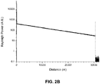
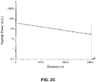
- Figures 2A-2C respectively illustrate coherent fading noise for Rayleigh power without tuning, with a 4 nm scan, and with a 35 nm scan, each performed at a 10 ns pulse with 1 m spatial resolution, according to an example of the present disclosure.
- use of a broadband source or the frequency sweep of a narrow source reduces interferences, which are observable as noise and referred to as coherent fading noise.
- the sensor 100 Based on the determination of the Brillouin power and the Rayleigh power, the sensor 100 provides for temperature and strain determination at high spatial resolution.
- the Brillouin power may be determined based on the B-OTDR functionality of the sensor 100, and the Rayleigh power may be determined based on the OTDR functionality of the sensor 100.
- the B-OTDR functionality of the sensor 100 provides for measurement of the Brillouin frequency shift and the Brillouin power.
- the Brillouin power may be normalized to the Rayleigh power to remove the power variations associated with fiber loss.
- the Brillouin power may be normalized to the Rayleigh power by dividing the Brillouin power with respect to the Rayleigh power.
- chip temperature of the laser source chip may be used for coarse tuning.
- a table of chip temperatures may be used as a guide to determine tuning values for the laser sources of the Laser Beam-1 and the Laser Beam-2.
- laser source chip operating current may be used for fine tuning. That is, with respect to the Brillouin and Rayleigh trace determination, the chip temperature and the laser source chip operating current may be used to control the offset frequency shift between the Laser Beam-1 and the Laser Beam-2.
- a feedback loop on chip temperature and operating current may be applied between the Laser Beam-1, the Laser Beam-2, and the photodiode 114, to maintain a constant beat frequency for the Laser Beam-1 and the Laser Beam-2.
- the beat frequency of the laser beams may be maintained as needed based on a determination of chip temperature and operating current of the laser sources.
- the frequency of the beat frequency produced on a fast photodiode is evaluated with a counter of zero-crossings per unit time.
- one technique for determining an offset frequency shift associated with a laser beam is to count the zero-crossings. For example, a comparator with a zero level may be used to determine each time the zero level is crossed. Based on the number of times the zero level is crossed, the offset frequency shift associated with a laser beam may be determined.
- 1 MHz of frequency may correspond to 1° C of temperature change.
- the RF bandwidth of the detection may be specified at 1 MHz or greater.
- a relatively large detection bandwidth may be utilized.
- a low-pass filter may be used with respect to the Brillouin trace determination, and a band-pass filter may be used with respect to the Rayleigh trace determination.
- a RF bandwidth lower than 1 MHz may equate to a spatial resolution greater than 100 m, which may not be relevant with respect to distributed sensing.
- the coherent signal may be demodulated by mixing the output of the photodiode 114 with the output of the coherent detection at the photodiodes for the coherent receiver 132.
- a variation curve of the two laser beam frequencies versus temperature may be determined.
- the variation curve may be used to calibrate the laser sources for the Laser Beam-1 and the Laser Beam-2.
- a feedback loop may be maintained between the laser sources on the operating current and the photodiode 114 for fine frequency difference adjustments.
- sweep may be performed while the OTDR acquisitions are processed and averaged.
- the OTDR acquisitions may be processed and averaged by using a matrix of DFBs covering C-Band.
- a first matrix of DFBs may be used for Laser Beam-1, and a second matrix of DFBs may be used for Laser Beam-2.
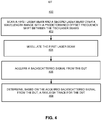
- Figures 3 and 4 respectively illustrate flowcharts of methods 300 and 400 for Brillouin trace and Rayleigh trace determination, according to examples.
- the methods 300 and 400 may be implemented on the Brillouin and Rayleigh distributed sensor described above with reference to Figures 1-2C by way of example and not limitation.
- the methods 300 and 400 may be practiced in other systems.
- the method 300 may include maintaining a predetermined offset frequency shift between the Laser Beam-1 (e.g., first laser beam) and the Laser Beam-2 (e.g., second laser beam).
- the predetermined offset frequency shift may be relative to a predetermined frequency of either the Laser Beam-1 or the Laser Beam-2.
- the photodiode 114 may acquire a beat frequency between the first laser beam and the second laser beam, where the beat frequency is used to maintain a predetermined offset frequency shift between the Laser Beam-1 and the Laser Beam-2.
- the method 300 may include modulating the Laser Beam-1.
- the modulated Laser Beam-1 is to be injected into the DUT.
- the modulator 108 may modulate the Laser Beam-1.
- the DUT may include the optical fiber 110.
- the method 300 may include acquiring a backscattered signal from the DUT.
- the backscattered signal results from the modulated Laser Beam-1 injected into the DUT.
- the Laser Beam-2 may be used as a local oscillator.
- the coherent receiver 132 may acquire a backscattered signal from the DUT.
- the method 300 may include determining, based on the acquired backscattered signal from the DUT, a Brillouin trace for the DUT.
- the sensor controller 130 may operate in conjunction with the coherent receiver 132 to determine a Brillouin trace for the DUT.
- the method 300 may further include repeating the acquisition of the backscattered signal from the DUT for a plurality of frequency shifts. For example, assuming that a Brillouin trace is determined at approximately 10.8 GHz, the acquisitions may be acquired for various frequency shifts in the range of approximately 10.7 GHz to 10.9 GHz in increments of 1.0 MHz - 10.0 MHz.
- the method 300 may include sampling, based on the repeated acquisitions corresponding to the plurality of frequency shifts and the acquisition of the backscattered signal from the DUT, a distributed Brillouin spectra.
- the method 300 may include determining, based on the sampling of the distributed Brillouin spectra, a resonant Brillouin frequency shift along the DUT.
- the method 300 may further include determining, based on the sampling of the distributed Brillouin spectra, integrated Brillouin power by performing an integration operation with respect to the resonant Brillouin frequency shift.
- the method 300 may further include scanning the Laser Beam-1 and the Laser Beam-2 over a wavelength range with a different predetermined offset frequency shift between the two laser beams.
- the different predetermined offset frequency shift may be approximately 240 MHz.
- the method 300 may include further modulating the Laser Beam-1 associated with the different predetermined offset frequency shift.
- the further modulated Laser Beam-1 is to be injected into the DUT.
- the method 300 may include further acquiring a further backscattered signal from the DUT.
- the further backscattered signal may be based on the further modulated Laser Beam-1 injected into the DUT.
- the Laser Beam-2 is to be used as the local oscillator.
- the method 300 may include determining, based on the further acquired backscattered signal from the DUT, a Rayleigh trace for the DUT.
- the Rayleigh trace may represent the Rayleigh power as function of time or distance along the optical fiber 110.
- the method 300 may further include determining, based on the integrated Brillouin power, the Rayleigh power, and the resonant Brillouin frequency shift along the DUT, temperature and strain associated with the DUT.
- the method 400 may include scanning the Laser Beam-1 (e.g., first laser beam) and the Laser Beam-2 (e.g., second laser beam) over a wavelength range with a predetermined offset frequency shift between the two laser beams.
- the photodiode 114 may acquire a beat frequency between the first laser beam and the second laser beam, where the beat frequency is used to maintain a predetermined offset frequency shift between the Laser Beam-1 and the Laser Beam-2.
- the predetermined offset frequency shift is relative to a predetermined frequency of either the Laser Beam-1 or the Laser Beam-2.
- the method 400 may include modulating the Laser Beam-1.
- the modulator 108 may modulate the Laser Beam-1.
- the modulated Laser Beam-1 is to be injected into the DUT.
- the method 400 may include acquiring a backscattered signal from the DUT.
- the backscattered signal results from the modulated Laser Beam-1 injected into the DUT.
- the Laser Beam-2 is to be used as a local oscillator.
- the coherent receiver 132 may acquire a backscattered signal from the DUT.
- the method 400 may include determining, based on the acquired backscattered signal from the DUT, a Rayleigh trace for the DUT.
- the sensor controller 130 may operate in conjunction with the coherent receiver 132 to determine a Rayleigh trace for the DUT.
- the method 400 may further include repeating the acquisition of the backscattered signal from the DUT for the predetermined offset frequency shift.
- the method 400 may include averaging, during scanning of the Laser Beam-1 and the Laser Beam-2 over the wavelength range with the predetermined offset frequency shift between the two laser beams, the repeated acquisitions of the backscattered signal from the DUT for the predetermined offset frequency shift to reduce coherent fading noises.
- the method 400 may further include maintaining a different predetermined offset frequency shift between the Laser Beam-1 and the Laser Beam-2.
- the different predetermined offset frequency shift may be approximately 10.8 GHz.
- the method 400 may include further modulating the Laser Beam-1 associated with the different predetermined offset frequency shift.
- the further modulated Laser Beam-1 is to be injected into the DUT.
- the method 400 may include further acquiring a further backscattered signal from the DUT.
- the further backscattered signal is based on the further modulated Laser Beam-1 injected into the DUT.
- the Laser Beam-2 is to be used as the local oscillator.
- the method 400 may include determining, based on the further acquired backscattered signal from the DUT, a Brillouin trace for the DUT.
- the method 400 may further include determining, based on the Brillouin trace, Brillouin power associated with the DUT.
- the method 400 may include normalizing the Brillouin power with respect to the Rayleigh power to remove power variations associated with the DUT.
- the method 400 may include determining, based on the normalized Brillouin power and a resonant Brillouin frequency shift along the DUT, temperature and strain associated with the DUT.
- Figure 5 shows a computer system 500 that may be used with the examples described herein.
- the computer system may represent a generic platform that includes components that may be in a server or another computer system.
- the computer system 500 may be used as part of a platform for the sensor controller 130.
- the computer system 500 may execute, by a processor (e.g., a single or multiple processors) or other hardware processing circuit, the methods, functions and other processes described herein.
- a processor e.g., a single or multiple processors
- a computer readable medium which may be non-transitory, such as hardware storage devices (e.g., RAM (random access memory), ROM (read only memory), EPROM (erasable, programmable ROM), EEPROM (electrically erasable, programmable ROM), hard drives, and flash memory).
- RAM random access memory
- ROM read only memory
- EPROM erasable, programmable ROM
- EEPROM electrically erasable, programmable ROM
- hard drives e.g., hard drives, and flash memory
- the computer system 500 may include a processor 502 that may implement or execute machine readable instructions performing some or all of the methods, functions and other processes described herein. Commands and data from the processor 502 may be communicated over a communication bus 504.
- the computer system may also include a main memory 506, such as a random access memory (RAM), where the machine readable instructions and data for the processor 502 may reside during runtime, and a secondary data storage 508, which may be non-volatile and stores machine readable instructions and data.
- the memory and data storage are examples of computer readable mediums.
- the memory 506 may include the sensor controller 130 including machine readable instructions residing in the memory 506 during runtime and executed by the processor 502.
- the computer system 500 may include an I/O device 510, such as a keyboard, a mouse, a display, etc.
- the computer system may include a network interface 512 for connecting to a network.
- Other known electronic components may be added or substituted in the computer system.
- the processor 502 may be designated as a hardware processor.
- the processor 502 may execute operations associated with various components of the Brillouin and Rayleigh distributed sensor 100.
- the processor 502 may execute operations associated with the sensor controller 130, etc.
Landscapes
- Physics & Mathematics (AREA)
- General Physics & Mathematics (AREA)
- Optics & Photonics (AREA)
- Chemical & Material Sciences (AREA)
- Analytical Chemistry (AREA)
- Optical Transform (AREA)
- Length Measuring Devices By Optical Means (AREA)
- Testing Of Optical Devices Or Fibers (AREA)
Applications Claiming Priority (3)
| Application Number | Priority Date | Filing Date | Title |
|---|---|---|---|
| US15/130,287 US10073006B2 (en) | 2016-04-15 | 2016-04-15 | Brillouin and rayleigh distributed sensor |
| EP19173023.3A EP3588015B1 (de) | 2016-04-15 | 2017-03-24 | Brillouin- und rayleigh-verteilter sensor |
| EP17162914.0A EP3232165B1 (de) | 2016-04-15 | 2017-03-24 | Brillouin- und rayleigh-verteilter sensor |
Related Parent Applications (4)
| Application Number | Title | Priority Date | Filing Date |
|---|---|---|---|
| EP19173023.3A Division EP3588015B1 (de) | 2016-04-15 | 2017-03-24 | Brillouin- und rayleigh-verteilter sensor |
| EP19173023.3A Division-Into EP3588015B1 (de) | 2016-04-15 | 2017-03-24 | Brillouin- und rayleigh-verteilter sensor |
| EP17162914.0A Division EP3232165B1 (de) | 2016-04-15 | 2017-03-24 | Brillouin- und rayleigh-verteilter sensor |
| EP17162914.0A Previously-Filed-Application EP3232165B1 (de) | 2016-04-15 | 2017-03-24 | Brillouin- und rayleigh-verteilter sensor |
Publications (2)
| Publication Number | Publication Date |
|---|---|
| EP3896401A1 true EP3896401A1 (de) | 2021-10-20 |
| EP3896401B1 EP3896401B1 (de) | 2023-07-05 |
Family
ID=58448373
Family Applications (3)
| Application Number | Title | Priority Date | Filing Date |
|---|---|---|---|
| EP21169692.7A Active EP3896401B1 (de) | 2016-04-15 | 2017-03-24 | Brillouin- und rayleigh-verteilter sensor |
| EP19173023.3A Active EP3588015B1 (de) | 2016-04-15 | 2017-03-24 | Brillouin- und rayleigh-verteilter sensor |
| EP17162914.0A Active EP3232165B1 (de) | 2016-04-15 | 2017-03-24 | Brillouin- und rayleigh-verteilter sensor |
Family Applications After (2)
| Application Number | Title | Priority Date | Filing Date |
|---|---|---|---|
| EP19173023.3A Active EP3588015B1 (de) | 2016-04-15 | 2017-03-24 | Brillouin- und rayleigh-verteilter sensor |
| EP17162914.0A Active EP3232165B1 (de) | 2016-04-15 | 2017-03-24 | Brillouin- und rayleigh-verteilter sensor |
Country Status (3)
| Country | Link |
|---|---|
| US (3) | US10073006B2 (de) |
| EP (3) | EP3896401B1 (de) |
| JP (1) | JP6612284B2 (de) |
Families Citing this family (31)
| Publication number | Priority date | Publication date | Assignee | Title |
|---|---|---|---|---|
| GB201601060D0 (en) * | 2016-01-20 | 2016-03-02 | Fotech Solutions Ltd | Distributed optical fibre sensors |
| US9983094B2 (en) * | 2016-09-09 | 2018-05-29 | Viavi Solutions Inc. | Temperature or strain distribution sensor comprising a coherent receiver to determine a temperature or a strain associated with a device under test |
| JP6705353B2 (ja) * | 2016-09-30 | 2020-06-03 | 沖電気工業株式会社 | 光ファイバ歪み及び温度測定装置 |
| CN108614278B (zh) * | 2018-05-04 | 2020-03-03 | 南京航空航天大学 | 一种基于偏振调制的大气激光遥感方法及偏振激光雷达 |
| KR102040598B1 (ko) * | 2018-05-16 | 2019-11-27 | 한국표준과학연구원 | 시간차를 갖는 펌프광과 탐색광의 위상 코드 변조를 사용하는 광섬유 bocda 센서 |
| CN108917974B (zh) * | 2018-09-12 | 2023-08-11 | 武汉昊衡科技有限公司 | 基于ofdr的硅光芯片温度测量装置及方法 |
| CN109375534B (zh) * | 2018-09-25 | 2021-06-25 | 华中科技大学鄂州工业技术研究院 | 一种瑞利布里渊散射信号采集与检测的同步控制方法及系统 |
| DE102018124435A1 (de) * | 2018-10-03 | 2020-04-09 | Nkt Photonics Gmbh | Verteilte Messvorrichtung |
| KR102749855B1 (ko) | 2019-07-24 | 2025-01-02 | 삼성전자주식회사 | 미세먼지 측정 장치 및 방법 |
| MY197170A (en) * | 2019-09-13 | 2023-05-28 | Petroliam Nasional Berhad Petronas | Optical fiber distribution measurement system and signal processing method for optical fiber distribution measurement |
| CN112781811B (zh) * | 2019-11-07 | 2023-02-17 | 中国石油化工股份有限公司 | 检测接管泄漏的方法、装置和系统 |
| TWI740422B (zh) * | 2020-03-23 | 2021-09-21 | 國立臺灣科技大學 | 混成光學感測系統 |
| CN113517922B (zh) * | 2020-04-09 | 2022-09-02 | 华为技术有限公司 | 一种信号检测方法和光时域反射仪 |
| CA3177163A1 (en) * | 2020-04-28 | 2021-11-04 | Gideon Yoffe | Integrated coherent receiver for distributed fiber sensing apparatus |
| US12055803B2 (en) * | 2020-05-12 | 2024-08-06 | Nec Corporation | Distributed acoustic sensing using dynamic range suppression |
| JP7613139B2 (ja) * | 2021-02-02 | 2025-01-15 | 株式会社大林組 | 計測装置 |
| CN113375837B (zh) * | 2021-06-11 | 2022-05-17 | 中电科思仪科技股份有限公司 | 一种光量子botdr光纤温度系数自动测量方法及装置 |
| JP7517279B2 (ja) | 2021-08-03 | 2024-07-17 | 横河電機株式会社 | 測定装置及び測定方法 |
| CN113654581B (zh) * | 2021-08-12 | 2023-06-23 | 太原理工大学 | 一种分布式光纤煤矿顶板安全监测系统及方法 |
| EP4155708A1 (de) * | 2021-09-24 | 2023-03-29 | Viavi Solutions Inc. | Optisches zeitbereichsreflektometer (otdr) einschliesslich kanalprüfer |
| US11942986B2 (en) | 2021-09-24 | 2024-03-26 | Viavi Solutions Inc. | Optical time-domain reflectometer (OTDR) including channel checker |
| AU2021470494B2 (en) * | 2021-10-18 | 2026-04-23 | Eoss Sa | Method and device for measuring a temperature and/or a strain in an optical fiber |
| US12442681B2 (en) | 2021-10-18 | 2025-10-14 | Nec Corporation | Distributed fiber optic sensing enabled self-coherent detection for data centers |
| CN114034374B (zh) * | 2022-01-07 | 2022-03-25 | 高勘(广州)技术有限公司 | 分布式光纤声波传感系统的控制方法及相关设备 |
| CN114526683B (zh) * | 2022-01-19 | 2023-05-23 | 太原理工大学 | 一种高空间分辨率温度和应变光纤传感系统及测量方法 |
| CN114526684B (zh) * | 2022-01-19 | 2023-08-08 | 太原理工大学 | 一种混沌外调制的布里渊光时域反射温度与应变检测装置 |
| IT202200004667A1 (it) | 2022-03-11 | 2022-06-11 | Sestosensor S R L | Rivelatore di fase e polarizzazione per sensori acustici distribuiti a fibre ottiche ed interrogatore basato sullo stesso |
| IT202200012014A1 (it) | 2022-06-07 | 2023-12-07 | Sestosensor S R L | Rivelatore interferometrico a miscelazione (interferodina) ed interrogatore per sensori distribuiti a fibre ottiche basato sullo stesso |
| CN115371716B (zh) * | 2022-10-25 | 2023-02-14 | 杭州水务数智科技股份有限公司 | 一种分布式光纤传感器多信号检测方法 |
| WO2025131752A1 (fr) | 2023-12-22 | 2025-06-26 | Commissariat A L'energie Atomique Et Aux Energies Alternatives | Dispositif de mesure de variations d'effort, de deformations mecaniques, de pressions hydrostatiques et de temperature, et procede de mesure associe |
| FR3157531A1 (fr) | 2023-12-22 | 2025-06-27 | Commissariat A L'energie Atomique Et Aux Energies Alternatives | Dispositif de mesure de variations d’effort, de déformations mécaniques, de pressions hydrostatiques et de température, et procédé de mesure associé |
Citations (5)
| Publication number | Priority date | Publication date | Assignee | Title |
|---|---|---|---|---|
| WO2011022829A1 (en) * | 2009-08-27 | 2011-03-03 | University Of New Brunswick | System and method for brillouin analysis |
| US20110090936A1 (en) * | 2009-10-21 | 2011-04-21 | Redfern Integrated Optics, Inc. | System and method for using coherently locked optical oscillator with brillouin frequency offset for fiber-optics-based distributed temperature and strain sensing applications |
| US20130020486A1 (en) * | 2010-04-13 | 2013-01-24 | China Jiliang University | Distributed optical fiber sensor based on roman and brillouin scattering |
| US20150211900A1 (en) * | 2012-08-17 | 2015-07-30 | Research Institute Of Innovative Technology For The Earth | Distribution measurement system for pressure, temperature, strain of material, monitoring method for carbon dioxide geological sequestration, assessing method for impact of carbon dioxide injection on integrity of strata, and monitoring method for freezing using same |
| US20150308923A1 (en) * | 2012-11-12 | 2015-10-29 | Omnisens Sa | A brillouin optoelectronic measurement method |
Family Cites Families (65)
| Publication number | Priority date | Publication date | Assignee | Title |
|---|---|---|---|---|
| US5363463A (en) * | 1982-08-06 | 1994-11-08 | Kleinerman Marcos Y | Remote sensing of physical variables with fiber optic systems |
| US5696863A (en) * | 1982-08-06 | 1997-12-09 | Kleinerman; Marcos Y. | Distributed fiber optic temperature sensors and systems |
| US5991479A (en) * | 1984-05-14 | 1999-11-23 | Kleinerman; Marcos Y. | Distributed fiber optic sensors and systems |
| JPS63313030A (ja) | 1987-06-15 | 1988-12-21 | Yokogawa Electric Corp | 光ファイバ試験装置 |
| JP2747565B2 (ja) * | 1989-06-29 | 1998-05-06 | 日本電信電話株式会社 | 光ファイバの曲率分布測定方法および装置 |
| US5173743A (en) * | 1991-05-28 | 1992-12-22 | Litton Systems, Inc. | Fiber optical time-division-multiplexed unbalanced pulsed interferometer with polarization fading compensation |
| JP3070880B2 (ja) | 1992-02-28 | 2000-07-31 | 日本電信電話株式会社 | 後方散乱光の測定装置 |
| JP3033677B2 (ja) * | 1995-09-26 | 2000-04-17 | 安藤電気株式会社 | 光ファイバ特性測定装置 |
| KR0160925B1 (ko) | 1995-10-10 | 1998-12-15 | 이준 | 광섬유 스트레인 분포 측정용 펄스광과 프로브광의 비트 주파수 안정화장치 |
| GB9626099D0 (en) * | 1996-12-16 | 1997-02-05 | King S College London | Distributed strain and temperature measuring system |
| GB9700269D0 (en) * | 1997-01-08 | 1997-02-26 | York Sensors Ltd | Improvements to optical time domain reflectometry |
| JPH1123419A (ja) | 1997-06-30 | 1999-01-29 | Ando Electric Co Ltd | 光ファイバ特性測定装置 |
| US6067391A (en) * | 1998-09-02 | 2000-05-23 | The United States Of America As Represented By The Secretary Of The Air Force | Multiply periodic refractive index modulated optical filters |
| JP3771754B2 (ja) * | 1999-08-09 | 2006-04-26 | 三菱重工業株式会社 | 光ファイバ変位計測装置 |
| NO324337B1 (no) * | 1999-09-15 | 2007-09-24 | Optoplan As | Anordning for maling av optiske bolgelengder |
| US6571027B2 (en) * | 1999-10-07 | 2003-05-27 | Peter W. E. Smith | Method and devices for time domain demultiplexing of serial fiber bragg grating sensor arrays |
| US6407846B1 (en) * | 2001-03-16 | 2002-06-18 | All Optical Networks, Inc. | Photonic wavelength shifting method |
| US20030234921A1 (en) * | 2002-06-21 | 2003-12-25 | Tsutomu Yamate | Method for measuring and calibrating measurements using optical fiber distributed sensor |
| JP3930023B2 (ja) * | 2002-11-01 | 2007-06-13 | 欣増 岸田 | 分布型光ファイバセンサシステム |
| GB0409865D0 (en) * | 2004-05-01 | 2004-06-09 | Sensornet Ltd | Direct measurement of brillouin frequency in distributed optical sensing systems |
| EP1747486A2 (de) * | 2004-05-15 | 2007-01-31 | The Board of Trustees of The Leland Stanford Junior University | Verfahren zur charakterisierung von faser-bragg-gittern mittels iterativer verarbeitung |
| US7154082B2 (en) * | 2004-08-20 | 2006-12-26 | Pgs Americas, Inc. | Frequency division and/or wavelength division multiplexed recursive fiber optic telemetry scheme for an optical sensor array |
| EP1746403A1 (de) * | 2005-07-19 | 2007-01-24 | Agilent Technologies, Inc. | Optische Reflektometrieanalyse mit einer Zeitanpassung auf Teil-Ansprechsignalen |
| US8379217B2 (en) * | 2006-03-23 | 2013-02-19 | General Electric Company | System and method for optical sensor interrogation |
| US7372574B2 (en) * | 2005-12-09 | 2008-05-13 | Honeywell International Inc. | System and method for stabilizing light sources in resonator gyro |
| EP3143926B1 (de) * | 2006-02-08 | 2020-07-01 | The General Hospital Corporation | Verfahren, anordnungen und systeme zum abrufen von informationen im zusammenhang mit einer anatomischen probe mithilfe eines optischen mikroskops |
| US7463360B2 (en) * | 2006-04-18 | 2008-12-09 | Honeywell International Inc. | Optical resonator gyro with integrated external cavity beam generator |
| US7499151B2 (en) | 2006-06-05 | 2009-03-03 | University Of Ottawa | Distributed Brillouin sensor system based on DFB lasers using offset locking |
| US7859654B2 (en) * | 2008-07-17 | 2010-12-28 | Schlumberger Technology Corporation | Frequency-scanned optical time domain reflectometry |
| WO2010061718A1 (ja) | 2008-11-27 | 2010-06-03 | ニューブレクス株式会社 | 分布型光ファイバセンサ |
| GB0919899D0 (en) * | 2009-11-13 | 2009-12-30 | Qinetiq Ltd | Fibre optic distributed sensing |
| US9267821B2 (en) * | 2010-01-28 | 2016-02-23 | Baker Hughes Incorporated | Combined swept-carrier and swept-modulation frequency optical frequency domain reflectometry |
| US8505625B2 (en) * | 2010-06-16 | 2013-08-13 | Halliburton Energy Services, Inc. | Controlling well operations based on monitored parameters of cement health |
| KR101207345B1 (ko) * | 2010-08-05 | 2012-12-05 | 한국표준과학연구원 | 자동보정 기능을 갖는 광섬유 분포 온도 센서 시스템 및 이를 이용한 온도 측정방법 |
| WO2012030814A2 (en) * | 2010-09-01 | 2012-03-08 | Schlumberger Canada Limited | Distributed fiber optic sensor system with improved linearity |
| GB201020827D0 (en) * | 2010-12-08 | 2011-01-19 | Fotech Solutions Ltd | Distrubuted optical fibre sensor |
| CN103314276B (zh) * | 2010-12-22 | 2016-08-10 | 奥姆尼森股份公司 | 布里渊光电测量方法和设备 |
| EP3838123A1 (de) * | 2011-04-29 | 2021-06-23 | The General Hospital Corporation | Verfahren und anordnungen zur gewinnung von informationen und zur bereitstellung von analysen für biologische gewebe |
| WO2012156978A1 (en) * | 2011-05-18 | 2012-11-22 | Bar Ilan University | Distributed sensing employing stimulated brillouin scattering in optical fibers |
| RU2573614C2 (ru) * | 2011-07-27 | 2016-01-20 | Омнисанс Са | Датчик и способ измерения |
| US9546915B2 (en) * | 2011-10-12 | 2017-01-17 | Baker Hughes Incorporated | Enhancing functionality of reflectometry based systems using parallel mixing operations |
| JP5972403B2 (ja) * | 2012-03-02 | 2016-08-17 | オーエフエス ファイテル,エルエルシー | Tdmおよびwdmベースのfbgセンサアレイシステム |
| WO2013185810A1 (en) * | 2012-06-13 | 2013-12-19 | Omnisens Sa | A sensing system and method for distributed brillouin sensing |
| US9360304B2 (en) * | 2012-08-10 | 2016-06-07 | Research Institute Of Innovative Technology For Th | Method for measuring volumetric changes of object |
| JP5851630B2 (ja) * | 2012-11-30 | 2016-02-03 | ニューブレクス株式会社 | 3次元位置計測装置 |
| CN103152097B (zh) * | 2013-03-12 | 2015-10-21 | 电子科技大学 | 一种采用随机激光放大的偏振及相位敏感光时域反射计 |
| US9804001B2 (en) * | 2013-03-18 | 2017-10-31 | Omnisens S.A. | Brillouin optical distributed sensing device and method with improved tolerance to sensor failure |
| US20150003834A1 (en) * | 2013-07-01 | 2015-01-01 | Xuekang Shan | Brillouin Strain and Temperature sensor incorporating a frequency offset locked DFB laser pair |
| EP3062078B1 (de) * | 2013-10-25 | 2019-07-03 | Neubrex Co., Ltd. | Faseroptisches biodiagnostisches sensorsystem und vaskuläre einsetzvorrichtung zur messung der druckverteilung |
| GB2523319B (en) * | 2014-02-19 | 2017-08-16 | Ap Sensing Gmbh | Distributed optical sensing with two-step evaluation |
| US10247581B2 (en) * | 2014-04-28 | 2019-04-02 | Optoplan As | Interferometric optical fibre sensor system and method of interrogation |
| WO2015170355A1 (en) * | 2014-05-05 | 2015-11-12 | Filippo Bastianini | Apparatus for interrogating distributed optical fibre sensors using a stimulated brillouin scattering optical frequency-domain interferometer |
| JP2017525435A (ja) * | 2014-07-25 | 2017-09-07 | ザ ジェネラル ホスピタル コーポレイション | インビボ・イメージングおよび診断のための機器、デバイスならびに方法 |
| US9964420B2 (en) * | 2014-11-03 | 2018-05-08 | Ofs Fitel, Llc | Distributed brillouin sensor |
| US20160204571A1 (en) * | 2015-01-14 | 2016-07-14 | Honeywell International Inc. | Systems and methods for an optical frequency comb stimulated brillouin scattering gyroscope with rigid optical waveguide resonator |
| GB201503861D0 (en) * | 2015-03-06 | 2015-04-22 | Silixa Ltd | Method and apparatus for optical sensing |
| JP6308160B2 (ja) * | 2015-03-31 | 2018-04-11 | 沖電気工業株式会社 | 光ファイバ歪み測定装置及び光ファイバ歪み測定方法 |
| US20170010385A1 (en) * | 2015-07-08 | 2017-01-12 | Schlumberger Technology Corporation | Fiber optic array having densely spaced, weak reflectors |
| DE102015114670A1 (de) * | 2015-09-02 | 2017-03-02 | Lios Technology Gmbh | Vorrichtung und Verfahren zur ortsaufgelösten Messung von Temperatur und/oder Dehnung vermittels Brillouin-Streuung |
| US10197471B2 (en) * | 2015-09-21 | 2019-02-05 | Corning Incorporated | Methods and devices for measuring properties of coatings on optical fibers |
| US10323925B2 (en) * | 2015-10-23 | 2019-06-18 | University Of Washington | Compact portable double differential fiber optic Sagnac interferometer |
| US10359302B2 (en) * | 2015-12-18 | 2019-07-23 | Schlumberger Technology Corporation | Non-linear interactions with backscattered light |
| US9983094B2 (en) * | 2016-09-09 | 2018-05-29 | Viavi Solutions Inc. | Temperature or strain distribution sensor comprising a coherent receiver to determine a temperature or a strain associated with a device under test |
| JP6705353B2 (ja) * | 2016-09-30 | 2020-06-03 | 沖電気工業株式会社 | 光ファイバ歪み及び温度測定装置 |
| WO2020051537A2 (en) * | 2018-09-06 | 2020-03-12 | Adelos, Inc. | Optical mandrel, optical-fiber assembly including an optical mandrel, and system for detecting an acoustic signal incident on an optical-fiber assembly |
-
2016
- 2016-04-15 US US15/130,287 patent/US10073006B2/en active Active
-
2017
- 2017-03-24 EP EP21169692.7A patent/EP3896401B1/de active Active
- 2017-03-24 EP EP19173023.3A patent/EP3588015B1/de active Active
- 2017-03-24 EP EP17162914.0A patent/EP3232165B1/de active Active
- 2017-04-14 JP JP2017080227A patent/JP6612284B2/ja active Active
-
2018
- 2018-08-09 US US16/059,837 patent/US10876925B2/en active Active
-
2020
- 2020-12-01 US US17/108,680 patent/US11422060B2/en active Active
Patent Citations (5)
| Publication number | Priority date | Publication date | Assignee | Title |
|---|---|---|---|---|
| WO2011022829A1 (en) * | 2009-08-27 | 2011-03-03 | University Of New Brunswick | System and method for brillouin analysis |
| US20110090936A1 (en) * | 2009-10-21 | 2011-04-21 | Redfern Integrated Optics, Inc. | System and method for using coherently locked optical oscillator with brillouin frequency offset for fiber-optics-based distributed temperature and strain sensing applications |
| US20130020486A1 (en) * | 2010-04-13 | 2013-01-24 | China Jiliang University | Distributed optical fiber sensor based on roman and brillouin scattering |
| US20150211900A1 (en) * | 2012-08-17 | 2015-07-30 | Research Institute Of Innovative Technology For The Earth | Distribution measurement system for pressure, temperature, strain of material, monitoring method for carbon dioxide geological sequestration, assessing method for impact of carbon dioxide injection on integrity of strata, and monitoring method for freezing using same |
| US20150308923A1 (en) * | 2012-11-12 | 2015-10-29 | Omnisens Sa | A brillouin optoelectronic measurement method |
Non-Patent Citations (1)
| Title |
|---|
| TOMASZ KAWALEC ET AL: "Construction and performance of an optical phase and frequency lock of diode lasers", OPTICAL ENGINEERING., vol. 52, no. 12, 16 December 2013 (2013-12-16), BELLINGHAM, pages 126105, XP055404400, ISSN: 0091-3286, DOI: 10.1117/1.OE.52.12.126105 * |
Also Published As
| Publication number | Publication date |
|---|---|
| JP2017198668A (ja) | 2017-11-02 |
| EP3232165B1 (de) | 2019-05-08 |
| US11422060B2 (en) | 2022-08-23 |
| US20180348086A1 (en) | 2018-12-06 |
| EP3896401B1 (de) | 2023-07-05 |
| EP3588015A1 (de) | 2020-01-01 |
| EP3588015B1 (de) | 2021-06-23 |
| US10073006B2 (en) | 2018-09-11 |
| US10876925B2 (en) | 2020-12-29 |
| EP3232165A1 (de) | 2017-10-18 |
| JP6612284B2 (ja) | 2019-11-27 |
| US20170299463A1 (en) | 2017-10-19 |
| US20210080350A1 (en) | 2021-03-18 |
Similar Documents
| Publication | Publication Date | Title |
|---|---|---|
| US11422060B2 (en) | Brillouin and rayleigh distributed sensor | |
| US10539476B2 (en) | Temperature or strain distribution sensor comprising a coherent receiver to determine a temperature or a strain associated with a device under test | |
| Von Der Weid et al. | On the characterization of optical fiber network components with optical frequency domain reflectometry | |
| US9804001B2 (en) | Brillouin optical distributed sensing device and method with improved tolerance to sensor failure | |
| CN102607451B (zh) | 波长扫描型布里渊光时域反射仪 | |
| CN105490738A (zh) | 基于频率合成的光频域反射方法及系统 | |
| US9500562B2 (en) | Kerr phase-interrogator for sensing and signal processing applications | |
| CN212752265U (zh) | 一种采用edfa放大装置检测瑞利散射信号强度的系统 | |
| Xiao et al. | Phase-noise-cancelled FMCW Lidar based on CS-DSB modulation and injection-locking technique | |
| US11942986B2 (en) | Optical time-domain reflectometer (OTDR) including channel checker | |
| CN112104415B (zh) | 一种采用edfa放大装置检测瑞利散射信号强度的系统 | |
| US12255682B2 (en) | Optical time-domain reflectometer (OTDR) including channel checker | |
| Diaz et al. | High performance Brillouin distributed fibre sensor | |
| WO2020022921A1 (ru) | Способ и устройство распределенного измерения двулучепреломления в волокнах с сохранением поляризации (варианты) | |
| RU2624801C1 (ru) | Способ измерения сдвига частоты рассеяния мандельштама-бриллюэна на длине оптического волокна | |
| WO2025088669A1 (ja) | ブリルアン散乱測定システム | |
| RU2624827C1 (ru) | Способ измерения сдвига частоты рассеяния мандельштама-бриллюэна на длине оптического волокна | |
| JP5521178B2 (ja) | 時間ゲート付き光検出装置およびこれを用いた多点計測システム | |
| Bergman et al. | Self-heterodyne Brillouin dynamic gratings reflectometry | |
| CN121655616A (zh) | 基于少模光纤的多参量融合分布式光纤传感系统及方法 | |
| Li et al. | Measurement of distributed modal birefringence in a few-mode fiber based on Brillouin dynamic grating | |
| Kaczmarek et al. | Optical frequency domain reflectometer for diagnostics of short distance networks |
Legal Events
| Date | Code | Title | Description |
|---|---|---|---|
| PUAI | Public reference made under article 153(3) epc to a published international application that has entered the european phase |
Free format text: ORIGINAL CODE: 0009012 |
|
| STAA | Information on the status of an ep patent application or granted ep patent |
Free format text: STATUS: THE APPLICATION HAS BEEN PUBLISHED |
|
| AC | Divisional application: reference to earlier application |
Ref document number: 3232165 Country of ref document: EP Kind code of ref document: P Ref document number: 3588015 Country of ref document: EP Kind code of ref document: P |
|
| AK | Designated contracting states |
Kind code of ref document: A1 Designated state(s): AL AT BE BG CH CY CZ DE DK EE ES FI FR GB GR HR HU IE IS IT LI LT LU LV MC MK MT NL NO PL PT RO RS SE SI SK SM TR |
|
| B565 | Issuance of search results under rule 164(2) epc |
Effective date: 20210907 |
|
| STAA | Information on the status of an ep patent application or granted ep patent |
Free format text: STATUS: REQUEST FOR EXAMINATION WAS MADE |
|
| 17P | Request for examination filed |
Effective date: 20220419 |
|
| RBV | Designated contracting states (corrected) |
Designated state(s): AL AT BE BG CH CY CZ DE DK EE ES FI FR GB GR HR HU IE IS IT LI LT LU LV MC MK MT NL NO PL PT RO RS SE SI SK SM TR |
|
| RAP3 | Party data changed (applicant data changed or rights of an application transferred) |
Owner name: VIAVI SOLUTIONS INC. |
|
| GRAP | Despatch of communication of intention to grant a patent |
Free format text: ORIGINAL CODE: EPIDOSNIGR1 |
|
| STAA | Information on the status of an ep patent application or granted ep patent |
Free format text: STATUS: GRANT OF PATENT IS INTENDED |
|
| INTG | Intention to grant announced |
Effective date: 20230126 |
|
| GRAS | Grant fee paid |
Free format text: ORIGINAL CODE: EPIDOSNIGR3 |
|
| GRAA | (expected) grant |
Free format text: ORIGINAL CODE: 0009210 |
|
| STAA | Information on the status of an ep patent application or granted ep patent |
Free format text: STATUS: THE PATENT HAS BEEN GRANTED |
|
| AC | Divisional application: reference to earlier application |
Ref document number: 3232165 Country of ref document: EP Kind code of ref document: P Ref document number: 3588015 Country of ref document: EP Kind code of ref document: P |
|
| AK | Designated contracting states |
Kind code of ref document: B1 Designated state(s): AL AT BE BG CH CY CZ DE DK EE ES FI FR GB GR HR HU IE IS IT LI LT LU LV MC MK MT NL NO PL PT RO RS SE SI SK SM TR |
|
| P01 | Opt-out of the competence of the unified patent court (upc) registered |
Effective date: 20230530 |
|
| REG | Reference to a national code |
Ref country code: CH Ref legal event code: EP |
|
| REG | Reference to a national code |
Ref country code: AT Ref legal event code: REF Ref document number: 1585226 Country of ref document: AT Kind code of ref document: T Effective date: 20230715 |
|
| REG | Reference to a national code |
Ref country code: DE Ref legal event code: R096 Ref document number: 602017071103 Country of ref document: DE |
|
| REG | Reference to a national code |
Ref country code: IE Ref legal event code: FG4D |
|
| REG | Reference to a national code |
Ref country code: LT Ref legal event code: MG9D |
|
| REG | Reference to a national code |
Ref country code: NL Ref legal event code: MP Effective date: 20230705 |
|
| REG | Reference to a national code |
Ref country code: AT Ref legal event code: MK05 Ref document number: 1585226 Country of ref document: AT Kind code of ref document: T Effective date: 20230705 |
|
| PG25 | Lapsed in a contracting state [announced via postgrant information from national office to epo] |
Ref country code: NL Free format text: LAPSE BECAUSE OF FAILURE TO SUBMIT A TRANSLATION OF THE DESCRIPTION OR TO PAY THE FEE WITHIN THE PRESCRIBED TIME-LIMIT Effective date: 20230705 |
|
| PG25 | Lapsed in a contracting state [announced via postgrant information from national office to epo] |
Ref country code: GR Free format text: LAPSE BECAUSE OF FAILURE TO SUBMIT A TRANSLATION OF THE DESCRIPTION OR TO PAY THE FEE WITHIN THE PRESCRIBED TIME-LIMIT Effective date: 20231006 |
|
| PG25 | Lapsed in a contracting state [announced via postgrant information from national office to epo] |
Ref country code: ES Free format text: LAPSE BECAUSE OF FAILURE TO SUBMIT A TRANSLATION OF THE DESCRIPTION OR TO PAY THE FEE WITHIN THE PRESCRIBED TIME-LIMIT Effective date: 20230705 |
|
| PG25 | Lapsed in a contracting state [announced via postgrant information from national office to epo] |
Ref country code: IS Free format text: LAPSE BECAUSE OF FAILURE TO SUBMIT A TRANSLATION OF THE DESCRIPTION OR TO PAY THE FEE WITHIN THE PRESCRIBED TIME-LIMIT Effective date: 20231105 |
|
| PG25 | Lapsed in a contracting state [announced via postgrant information from national office to epo] |
Ref country code: SE Free format text: LAPSE BECAUSE OF FAILURE TO SUBMIT A TRANSLATION OF THE DESCRIPTION OR TO PAY THE FEE WITHIN THE PRESCRIBED TIME-LIMIT Effective date: 20230705 Ref country code: RS Free format text: LAPSE BECAUSE OF FAILURE TO SUBMIT A TRANSLATION OF THE DESCRIPTION OR TO PAY THE FEE WITHIN THE PRESCRIBED TIME-LIMIT Effective date: 20230705 Ref country code: PT Free format text: LAPSE BECAUSE OF FAILURE TO SUBMIT A TRANSLATION OF THE DESCRIPTION OR TO PAY THE FEE WITHIN THE PRESCRIBED TIME-LIMIT Effective date: 20231106 Ref country code: NO Free format text: LAPSE BECAUSE OF FAILURE TO SUBMIT A TRANSLATION OF THE DESCRIPTION OR TO PAY THE FEE WITHIN THE PRESCRIBED TIME-LIMIT Effective date: 20231005 Ref country code: LV Free format text: LAPSE BECAUSE OF FAILURE TO SUBMIT A TRANSLATION OF THE DESCRIPTION OR TO PAY THE FEE WITHIN THE PRESCRIBED TIME-LIMIT Effective date: 20230705 Ref country code: LT Free format text: LAPSE BECAUSE OF FAILURE TO SUBMIT A TRANSLATION OF THE DESCRIPTION OR TO PAY THE FEE WITHIN THE PRESCRIBED TIME-LIMIT Effective date: 20230705 Ref country code: IS Free format text: LAPSE BECAUSE OF FAILURE TO SUBMIT A TRANSLATION OF THE DESCRIPTION OR TO PAY THE FEE WITHIN THE PRESCRIBED TIME-LIMIT Effective date: 20231105 Ref country code: HR Free format text: LAPSE BECAUSE OF FAILURE TO SUBMIT A TRANSLATION OF THE DESCRIPTION OR TO PAY THE FEE WITHIN THE PRESCRIBED TIME-LIMIT Effective date: 20230705 Ref country code: GR Free format text: LAPSE BECAUSE OF FAILURE TO SUBMIT A TRANSLATION OF THE DESCRIPTION OR TO PAY THE FEE WITHIN THE PRESCRIBED TIME-LIMIT Effective date: 20231006 Ref country code: FI Free format text: LAPSE BECAUSE OF FAILURE TO SUBMIT A TRANSLATION OF THE DESCRIPTION OR TO PAY THE FEE WITHIN THE PRESCRIBED TIME-LIMIT Effective date: 20230705 Ref country code: ES Free format text: LAPSE BECAUSE OF FAILURE TO SUBMIT A TRANSLATION OF THE DESCRIPTION OR TO PAY THE FEE WITHIN THE PRESCRIBED TIME-LIMIT Effective date: 20230705 Ref country code: AT Free format text: LAPSE BECAUSE OF FAILURE TO SUBMIT A TRANSLATION OF THE DESCRIPTION OR TO PAY THE FEE WITHIN THE PRESCRIBED TIME-LIMIT Effective date: 20230705 |
|
| PG25 | Lapsed in a contracting state [announced via postgrant information from national office to epo] |
Ref country code: PL Free format text: LAPSE BECAUSE OF FAILURE TO SUBMIT A TRANSLATION OF THE DESCRIPTION OR TO PAY THE FEE WITHIN THE PRESCRIBED TIME-LIMIT Effective date: 20230705 |
|
| REG | Reference to a national code |
Ref country code: DE Ref legal event code: R097 Ref document number: 602017071103 Country of ref document: DE |
|
| PG25 | Lapsed in a contracting state [announced via postgrant information from national office to epo] |
Ref country code: SM Free format text: LAPSE BECAUSE OF FAILURE TO SUBMIT A TRANSLATION OF THE DESCRIPTION OR TO PAY THE FEE WITHIN THE PRESCRIBED TIME-LIMIT Effective date: 20230705 Ref country code: RO Free format text: LAPSE BECAUSE OF FAILURE TO SUBMIT A TRANSLATION OF THE DESCRIPTION OR TO PAY THE FEE WITHIN THE PRESCRIBED TIME-LIMIT Effective date: 20230705 Ref country code: EE Free format text: LAPSE BECAUSE OF FAILURE TO SUBMIT A TRANSLATION OF THE DESCRIPTION OR TO PAY THE FEE WITHIN THE PRESCRIBED TIME-LIMIT Effective date: 20230705 Ref country code: DK Free format text: LAPSE BECAUSE OF FAILURE TO SUBMIT A TRANSLATION OF THE DESCRIPTION OR TO PAY THE FEE WITHIN THE PRESCRIBED TIME-LIMIT Effective date: 20230705 Ref country code: CZ Free format text: LAPSE BECAUSE OF FAILURE TO SUBMIT A TRANSLATION OF THE DESCRIPTION OR TO PAY THE FEE WITHIN THE PRESCRIBED TIME-LIMIT Effective date: 20230705 Ref country code: SK Free format text: LAPSE BECAUSE OF FAILURE TO SUBMIT A TRANSLATION OF THE DESCRIPTION OR TO PAY THE FEE WITHIN THE PRESCRIBED TIME-LIMIT Effective date: 20230705 |
|
| PLBE | No opposition filed within time limit |
Free format text: ORIGINAL CODE: 0009261 |
|
| STAA | Information on the status of an ep patent application or granted ep patent |
Free format text: STATUS: NO OPPOSITION FILED WITHIN TIME LIMIT |
|
| PG25 | Lapsed in a contracting state [announced via postgrant information from national office to epo] |
Ref country code: IT Free format text: LAPSE BECAUSE OF FAILURE TO SUBMIT A TRANSLATION OF THE DESCRIPTION OR TO PAY THE FEE WITHIN THE PRESCRIBED TIME-LIMIT Effective date: 20230705 |
|
| 26N | No opposition filed |
Effective date: 20240408 |
|
| PG25 | Lapsed in a contracting state [announced via postgrant information from national office to epo] |
Ref country code: SI Free format text: LAPSE BECAUSE OF FAILURE TO SUBMIT A TRANSLATION OF THE DESCRIPTION OR TO PAY THE FEE WITHIN THE PRESCRIBED TIME-LIMIT Effective date: 20230705 |
|
| REG | Reference to a national code |
Ref country code: CH Ref legal event code: PL |
|
| PG25 | Lapsed in a contracting state [announced via postgrant information from national office to epo] |
Ref country code: BG Free format text: LAPSE BECAUSE OF FAILURE TO SUBMIT A TRANSLATION OF THE DESCRIPTION OR TO PAY THE FEE WITHIN THE PRESCRIBED TIME-LIMIT Effective date: 20230705 |
|
| PG25 | Lapsed in a contracting state [announced via postgrant information from national office to epo] |
Ref country code: LU Free format text: LAPSE BECAUSE OF NON-PAYMENT OF DUE FEES Effective date: 20240324 |
|
| PG25 | Lapsed in a contracting state [announced via postgrant information from national office to epo] |
Ref country code: MC Free format text: LAPSE BECAUSE OF FAILURE TO SUBMIT A TRANSLATION OF THE DESCRIPTION OR TO PAY THE FEE WITHIN THE PRESCRIBED TIME-LIMIT Effective date: 20230705 |
|
| PG25 | Lapsed in a contracting state [announced via postgrant information from national office to epo] |
Ref country code: MC Free format text: LAPSE BECAUSE OF FAILURE TO SUBMIT A TRANSLATION OF THE DESCRIPTION OR TO PAY THE FEE WITHIN THE PRESCRIBED TIME-LIMIT Effective date: 20230705 Ref country code: LU Free format text: LAPSE BECAUSE OF NON-PAYMENT OF DUE FEES Effective date: 20240324 Ref country code: BG Free format text: LAPSE BECAUSE OF FAILURE TO SUBMIT A TRANSLATION OF THE DESCRIPTION OR TO PAY THE FEE WITHIN THE PRESCRIBED TIME-LIMIT Effective date: 20230705 |
|
| REG | Reference to a national code |
Ref country code: BE Ref legal event code: MM Effective date: 20240331 |
|
| PG25 | Lapsed in a contracting state [announced via postgrant information from national office to epo] |
Ref country code: BE Free format text: LAPSE BECAUSE OF NON-PAYMENT OF DUE FEES Effective date: 20240331 |
|
| PG25 | Lapsed in a contracting state [announced via postgrant information from national office to epo] |
Ref country code: IE Free format text: LAPSE BECAUSE OF NON-PAYMENT OF DUE FEES Effective date: 20240324 |
|
| PG25 | Lapsed in a contracting state [announced via postgrant information from national office to epo] |
Ref country code: IE Free format text: LAPSE BECAUSE OF NON-PAYMENT OF DUE FEES Effective date: 20240324 Ref country code: BE Free format text: LAPSE BECAUSE OF NON-PAYMENT OF DUE FEES Effective date: 20240331 Ref country code: CH Free format text: LAPSE BECAUSE OF NON-PAYMENT OF DUE FEES Effective date: 20240331 |
|
| PGFP | Annual fee paid to national office [announced via postgrant information from national office to epo] |
Ref country code: DE Payment date: 20250331 Year of fee payment: 9 |
|
| PG25 | Lapsed in a contracting state [announced via postgrant information from national office to epo] |
Ref country code: CY Free format text: LAPSE BECAUSE OF FAILURE TO SUBMIT A TRANSLATION OF THE DESCRIPTION OR TO PAY THE FEE WITHIN THE PRESCRIBED TIME-LIMIT; INVALID AB INITIO Effective date: 20170324 |
|
| PG25 | Lapsed in a contracting state [announced via postgrant information from national office to epo] |
Ref country code: HU Free format text: LAPSE BECAUSE OF FAILURE TO SUBMIT A TRANSLATION OF THE DESCRIPTION OR TO PAY THE FEE WITHIN THE PRESCRIBED TIME-LIMIT; INVALID AB INITIO Effective date: 20170324 |
|
| PG25 | Lapsed in a contracting state [announced via postgrant information from national office to epo] |
Ref country code: TR Free format text: LAPSE BECAUSE OF FAILURE TO SUBMIT A TRANSLATION OF THE DESCRIPTION OR TO PAY THE FEE WITHIN THE PRESCRIBED TIME-LIMIT Effective date: 20230705 |
|
| PGFP | Annual fee paid to national office [announced via postgrant information from national office to epo] |
Ref country code: GB Payment date: 20260330 Year of fee payment: 10 |
|
| PGFP | Annual fee paid to national office [announced via postgrant information from national office to epo] |
Ref country code: FR Payment date: 20260327 Year of fee payment: 10 |