EP3896482B1 - Procédé de génération mise en oeuvre par ordinateur d'un ensemble de données synthétiques pour l'apprentissage d'un réseau neuronal convolutionnel d'un sar interférométrique - Google Patents
Procédé de génération mise en oeuvre par ordinateur d'un ensemble de données synthétiques pour l'apprentissage d'un réseau neuronal convolutionnel d'un sar interférométrique Download PDFInfo
- Publication number
- EP3896482B1 EP3896482B1 EP20169572.3A EP20169572A EP3896482B1 EP 3896482 B1 EP3896482 B1 EP 3896482B1 EP 20169572 A EP20169572 A EP 20169572A EP 3896482 B1 EP3896482 B1 EP 3896482B1
- Authority
- EP
- European Patent Office
- Prior art keywords
- images
- phase
- coherence
- category
- amplitude
- Prior art date
- Legal status (The legal status is an assumption and is not a legal conclusion. Google has not performed a legal analysis and makes no representation as to the accuracy of the status listed.)
- Active
Links
Images


Classifications
-
- G—PHYSICS
- G01—MEASURING; TESTING
- G01S—RADIO DIRECTION-FINDING; RADIO NAVIGATION; DETERMINING DISTANCE OR VELOCITY BY USE OF RADIO WAVES; LOCATING OR PRESENCE-DETECTING BY USE OF THE REFLECTION OR RERADIATION OF RADIO WAVES; ANALOGOUS ARRANGEMENTS USING OTHER WAVES
- G01S7/00—Details of systems according to groups G01S13/00, G01S15/00, G01S17/00
- G01S7/02—Details of systems according to groups G01S13/00, G01S15/00, G01S17/00 of systems according to group G01S13/00
- G01S7/40—Means for monitoring or calibrating
- G01S7/4052—Means for monitoring or calibrating by simulation of echoes
-
- G—PHYSICS
- G01—MEASURING; TESTING
- G01S—RADIO DIRECTION-FINDING; RADIO NAVIGATION; DETERMINING DISTANCE OR VELOCITY BY USE OF RADIO WAVES; LOCATING OR PRESENCE-DETECTING BY USE OF THE REFLECTION OR RERADIATION OF RADIO WAVES; ANALOGOUS ARRANGEMENTS USING OTHER WAVES
- G01S13/00—Systems using the reflection or reradiation of radio waves, e.g. radar systems; Analogous systems using reflection or reradiation of waves whose nature or wavelength is irrelevant or unspecified
- G01S13/88—Radar or analogous systems specially adapted for specific applications
- G01S13/89—Radar or analogous systems specially adapted for specific applications for mapping or imaging
- G01S13/90—Radar or analogous systems specially adapted for specific applications for mapping or imaging using synthetic aperture techniques, e.g. synthetic aperture radar [SAR] techniques
- G01S13/9021—SAR image post-processing techniques
- G01S13/9023—SAR image post-processing techniques combined with interferometric techniques
-
- G—PHYSICS
- G06—COMPUTING OR CALCULATING; COUNTING
- G06N—COMPUTING ARRANGEMENTS BASED ON SPECIFIC COMPUTATIONAL MODELS
- G06N3/00—Computing arrangements based on biological models
- G06N3/02—Neural networks
- G06N3/04—Architecture, e.g. interconnection topology
- G06N3/045—Combinations of networks
- G06N3/0455—Auto-encoder networks; Encoder-decoder networks
-
- G—PHYSICS
- G06—COMPUTING OR CALCULATING; COUNTING
- G06N—COMPUTING ARRANGEMENTS BASED ON SPECIFIC COMPUTATIONAL MODELS
- G06N3/00—Computing arrangements based on biological models
- G06N3/02—Neural networks
- G06N3/04—Architecture, e.g. interconnection topology
- G06N3/0464—Convolutional networks [CNN, ConvNet]
-
- G—PHYSICS
- G06—COMPUTING OR CALCULATING; COUNTING
- G06N—COMPUTING ARRANGEMENTS BASED ON SPECIFIC COMPUTATIONAL MODELS
- G06N3/00—Computing arrangements based on biological models
- G06N3/02—Neural networks
- G06N3/08—Learning methods
-
- G—PHYSICS
- G06—COMPUTING OR CALCULATING; COUNTING
- G06N—COMPUTING ARRANGEMENTS BASED ON SPECIFIC COMPUTATIONAL MODELS
- G06N3/00—Computing arrangements based on biological models
- G06N3/02—Neural networks
- G06N3/08—Learning methods
- G06N3/09—Supervised learning
-
- G—PHYSICS
- G06—COMPUTING OR CALCULATING; COUNTING
- G06N—COMPUTING ARRANGEMENTS BASED ON SPECIFIC COMPUTATIONAL MODELS
- G06N3/00—Computing arrangements based on biological models
- G06N3/02—Neural networks
- G06N3/04—Architecture, e.g. interconnection topology
- G06N3/045—Combinations of networks
Definitions
- the invention relates to a method for the computer-implemented generation of a synthetic data set for training a convolutional neural network for an Interferometric Synthetic Aperture Radar.
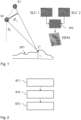
- Synthetic Aperture Radar Interferometry is a key remote sensing technique for the study of the geosphere. To the most significant applications belong e.g. the retrieval of surface topography SFT, i.e. digital elevation models DEM, and the observation of deformations. InSAR is based on the coherent acquisition of at least two complex SAR images SLC1, SCL2, called Single Look Complex (SLC). The phase difference between two SLCs SLC1, SLC2 (called interferometric phase or simply interferogram IFG) acquired from two slightly different sensor positions, encodes the information about the surface (terrain) topography SFT, as presented in Fig. 1 .
- interferometric phase or simply interferogram IFG The phase difference between two SLCs SLC1, SLC2 (called interferometric phase or simply interferogram IFG) acquired from two slightly different sensor positions, encodes the information about the surface (terrain) topography SFT, as presented in Fig. 1 .
- the acquisition geometry of the two SAR systems S1, S2 acquiring the SAR images SLC1, SLC2 is defined by an orthogonal baseline B ⁇ , a look angle ⁇ i , and an altitude of the SAR Systems S1, S2.
- a temporal separation between the two SLCs SLC1, SLC2 is present, a further phase term can be retrieved, caused by changes in the ground topography occurred during the time between the observations.
- the interferometric phase measurement is normally affected by noise, which arises depending on the nature of the observed scattering mechanism, the atmospheric conditions, as well as the acquisition geometry and sensor parameters.
- phase unwrapping is the process to add and subtract to each pixel multiples of 2 ⁇ phase values in order to reconstruct a phase field that is consistent all over the image. This procedure is heavily impacted by phase noise.
- a set of reliable (less noise-affected) pixels is selected according to the degree of correlation between the interferometric pair. This last quantity is the complex correlation between SLCs SLC1, SLC2 also indicated as coherence.
- CNN Convolutional Neural Networks
- the formation of such a large and variegated data set can instead rely on the generation of synthetic data, which is by far a much more critical aspect than the design of the network itself.
- the creation of a synthetic data set should generalize the estimation problem to all the possible circumstances that can appear in real interferometric SAR data.
- the interferometric signal may significantly vary from scene to scene depending on the acquisition geometry, the radar sensor parameters and acquisition modes, as well as the land cover of the imaged area.
- the spatial-domain approaches are mainly based on the assumption of wide-sense local stationarity (smooth variation) of the interferometric signal in a given neighborhood.
- a Maximum-Likelihood approach is proposed in [1] and further improved in [2], [3] by modifying the estimation window shape according to the shape and orientation of the interferometric fringes.
- the only aspect, which is considered for the modeling of the InSAR signal is that the interferometric phase signal is characterized by the presence of 2 ⁇ phase fringe patterns at different density, which depend on the acquisition geometry, the sensor parameters, and the scene topography.
- Further developments of spatial-domain filters are based on a large variety of patch-based approaches [4][5][6][7].
- the basic idea is the research of similar pixels prior to the actual filtering. In this way the predictors are selected according to a suitable distance metric rather than chosen as the spatially closest ones.
- the transformed-domain category instead, starts from the observation that the interferometric signal can be easily described in terms of alternative basis functions, as for examples the Fourier's one [8], [9], and the wavelet one [10]. In these cases, no assumptions are made on the amplitude values, while the phase is generated as fringe patterns of varying density and the coherence has only a slow varying spatial trend.
- CNNs Convolutional Neural Networks
- the authors propose different network architectures based on the one presented in [12], while the training is performed on synthetic [13] or on real [14] data, respectively.
- the synthetic training data are generated according to the observation of open pit mines only, which is a very specific observation scenario characterized by abrupt phase changes [13].
- the training based on real data exploits a pre-processing of the data in order to approximate an almost clean reference [14].
- CNNs strongly depends on the strategy used for the training of the network itself.
- a CNN needs to be trained with a large and variegated data set, which is able to represent the totality or, at least, the majority of the complex cases that can be observed in nature.
- the performance of the CNN estimator is highly influenced by the generalization capability and specificity of the used training data set [15]. Indeed, it is typical that a proposed methodology, based on a given CNN model, performs very well on the analyzed data set, while it performs poorly when tested on a different data set or on real data, as shown by the work in [13].
- a proper training data set should instead include significant samples, which are able to correctly model the physical phenomena actually observed in real data.
- CN 109 558 859 A discloses a method for computer-implemented generation of a synthetic data set for training a CNN for an InSAR system. According to this method, a number of interferometric phase images which is generated from a respective digital elevation model is retrieved. Each digital elevation model is back-geocoded from an image taken with a SAR system using a known acquisition geometry.
- CN 101 876 704 B1 discloses a method for simulating three-dimensional land scene echoes of an InSAR system.
- the method comprises the steps of, firstly, performing geometric modeling on three-dimensional land scenes and dividing the three-dimensional land scenes into facets which are adjacent to each other; then, performing electromagnetic modeling by using the facets as scatterers and calculating backscattering coefficients of the scatterers; and finally, generating echoes in parallel by calculating a single echo according to a signal model of an InSAR system.
- the invention provides a method for the computer-implemented generation of a synthetic data set for training a convolutional neural network for an Interferometric Synthetic Aperture Radar (InSAR).
- InSAR Interferometric Synthetic Aperture Radar
- the following steps i) to iii) are performed.
- step i) a number of interferometric phase images being generated from a respective digital elevation model, DEM, is retrieved, where each digital elevation model, DEM, is back-geocoded from an image taken with a SAR system using a known acquisition geometry.
- the generation process of a training data set considers an acquisition geometry, e.g.
- a number of amplitude images and coherence images is generated by providing different patterns derived from two sets, a first set comprising ramp profiles representing an increasing trend in one direction and a second set comprising natural patterns corresponding to scenarios taken from remotely sensed optical images and by mapping the natural pattern digital values into a same scale used for the ramp profile digital values.
- the ramp profiles can be regarded as digital values having a pure linear trend.
- a number of noisy images is generated by repeatedly grouping one of the phase images, one of the amplitude images and one of the coherence images into a triple and combining each triple to form a respective noisy image, wherein each of the noisy images is assigned to one of a plurality of different categories.
- the method provides a methodology for the standardization of the generation procedure of a synthetic data set, which is suitable for training CNNs for InSAR parameters estimation.
- the generation of the training set is based on the simulation of typical behaviors occurring in real InSAR data.
- the phase images are classified into one of two different categories, where the phase images of a first category of the two different categories are characterized by the presence of fringe patterns at low frequency and the phase images of a second category of the two different categories are characterized by the presence of fringe patterns at high frequency.
- Fringe patterns at low frequency correspond to flat terrain.
- Fringe patterns at high frequency correspond to high-relief terrain. The presence of both, relatively flat and high-relief terrain allows for the generation of synthetic interferograms, characterized by the presence of low- and high-frequency fringes, respectively.
- a first part of the amplitude images is represented by a first ramp profile with an increasing trend from left-to-right, or vice versa.
- a second part of the amplitude images is represented by a second ramp profile with an increasing trend from top-to-bottom, or vice versa.
- a third part of the amplitude images is represented by the natural patterns, where the natural pattern digital values are mapped into a first scale used for the ramp profile digital values.
- a first part of the coherence images is represented by a ramp profile with an increasing trend from left-to-right, or vice versa.
- a second part of the coherence images is represented by the natural patterns, where the natural pattern digital values are mapped into a second scale used for the ramp profile digital values, the second scale being different from the first scale.
- the second scale consists of digital values between 0 and 1, where digital values of the natural pattern and/or the ramp profile being smaller than a first threshold value are assigned to a random value between 0 and the first threshold value.
- the natural patterns display a large variety of different scenarios, ranging from natural environments to man-made structures. Therefore, they are well suited for training the neural network on features which can be found in nature. For example, use of the NWPU-RESISC45 [17] images can be made, which can be downloaded at [18].
- the phase images, the amplitude images and the coherence images are grouped in at least two of the following number of different categories. Preferably, all of the following six categories will be used for generating the set of training data.
- Category C1 a given number of amplitude images of the first part of the amplitude images; the same given number of coherence images of the first part of the coherence images; and a part of the given number of phase images of the first category and the remainder of the given number of phase images of the second category.
- Category C2 a given number of amplitude images of the second part of the amplitude images; the same given number of coherence images of the first part of the coherence images; and a part of the given number of phase images of the first category and the remainder of the given number of phase images of the second category.
- Category C3 a given number of amplitude images of the third part of the amplitude images; the same given number of coherence images of the first part of the coherence images; and a part of the given number of phase images of the first category and the remainder of the given number of phase images of the second category.
- Category C4 a given number of amplitude images of the second part of the amplitude images; the same given number of coherence images of the second part of the coherence images; and a part of the given number of phase images of the first category and the remainder of the given number of phase images of the second category.
- Category C5 a given number of amplitude images of the third part of the amplitude images; the same given number of coherence images of the second part of the coherence images; a part of the given number of phase images of the first category and the remainder of the given number of phase images of the second category.
- Category C6 a given number of amplitude images of the third part of the amplitude images; the same given number of coherence images of the second part of the coherence images; and the same given number of phase images of a third category characterized by the presence of steps.
- the phase images of category C6 enable considering abrupt phase jumps.
- the proposed combination of different patterns aims at simulating possible behaviors which can be found in real InSAR data.
- amplitude and coherence can either be directly correlated (as in category C1, where two left-to-right ramps, or vice versa, are used, or in categories C5 and C6, where natural patterns are used) or uncorrelated (as in categories C2, C3, and C4).
- the phase images of the third category is generated based on a coherence image characterized by the presence of fringe patterns at low frequency by pixelwise segmenting the corresponding coherence for digital values above a second threshold value, using two different intervals, a first interval being defined between the second threshold value and a third threshold value, and a second interval being defined between the third threshold value and 1, associating a random constant phase jump to each segment, allowing for phase jumps up to ⁇ ; and adding the phase jump to a phase image of the first category.
- the first, the second and the third threshold value it holds third threshold value > second threshold value > first threshold value.
- the phase jump results from two or more adjacent smaller phase jumps.
- This embodiment pays special attention to category C6, which is characterized by a different kind of phase pattern, with respect to all the other categories C1 to C5.
- the aim is to simulate the behavior of point-like scatterers or man-made structures, such as buildings. In these cases it is possible to see abrupt phase jumps in the data, in correspondence of a change in height of the considered feature and is therefore reasonable to associate such jumps to correlated high values of both, amplitude and coherence.
- a combination of one phase image, one amplitude image and one coherence image of a respective category is performed to derive an observed normalized complex interferogram.
- the combination consists of amplitude and coherence patterns of the categories C1 to C6 with the interferometric phase images at low- and high-frequency fringe patterns.
- the invention further relates to a method for training a convolutional neural network for an Interferometric Synthetic Aperture Radar.
- the following steps i) and ii) are performed.
- step i) a synthetic training data set with noisy images according to one or more preferred embodiments of the invention is generated.
- step ii) the convolutional neural network is trained with the training data set.
- the convolutional neural network is based on a U-Net model using a three-layer decoding path with skip connections.
- an input is connected to an output through a shortcut connection in order to match the output dimensions with the input ones.
- the noisy input data being presented by a complex interferogram is preprocessed by normalizing the complex interferogram and subsequently by decorrelating the data.
- the normalization comprises computing a normalized complex interferogram from the noisy image, estimating an amplitude by averaging intensities of two complex SAR images of the noisy image, where the estimation is applied to real and imaginary parts separately, and applying a maximum-likelihood estimation of the amplitude within a two-dimensional window.
- a L2-norm ( L 2 ) loss function is exploited, together with a regularization term ( R ), which applies to output values of the convolutional neural network if its absolute value is outside the interval [-1,1].
- a and b are decorrelated quantities corresponding to the real and imaginary parts of the noisy normalized complex interferogram, while the subscript 0 and the hat symbol indicate the corresponding noise-free and estimated parameters, respectively, and the term ⁇ weights the regularization function with respect to the L2-norm.
- the invention refers to a computer program product with a program code, which is stored on a non-transitory machine-readable carrier, configured for carrying out the method according to the invention or one or more preferred embodiments thereof when the program code is executed on a computer.
- the present invention provides a methodology for the standardization of the generation procedure of a synthetic data set, which is suitable for training CNNs for InSAR parameters estimation.
- the problem of the training set generation is solved by simulating typical behaviors occurring in real InSAR data.
- a SLC Single Look Complex
- Fig. 1 For statistically modeling the interferometric SAR signal, a SLC (Single Look Complex) as depicted in Fig. 1 and acquired by a SAR system is assumed to be a complex circular Gaussian variable, accordingly to the statistical description of coherent radar measurements in [1] for the statistical description of the interferometric signal.
- the normalized complex interferogram is
- the simulated noise depends on the choice of the set of initial noise-free parameters (amplitude, phase, and coherence). Therefore, their choice is a key aspect for the generation of the training data set.
- guidelines proposed in [15] may be used, which are expected to be considered in order to generate a training set that represents the generality of the problem.
- the approximation component refers to the representation of the main background physical information, while the detail component aims at completing the description of the physical problem by introducing realistic complex variations. In the present method, the approximation component is achieved by considering the interdependence between the noise-free interferometric parameters. Then the detail component is introduced by taking into account realistic spatial variation patterns for each of them.
- a recurring scenario comprises an interferometric phase and amplitude that show weakly correlated patterns or no correlation at all, whereas such dependence is often present between coherence and amplitude.
- each parameter can be assumed to present either smooth variation trends or abrupt changes, depending on the type of illuminated target.
- the interferometric phase presents fringe patterns of different spatial density depending on the local terrain slope, while the amplitude and the coherence may show slowly-varying textures, as well as edges and tiny details, in a similar way as natural patterns that can be found in optical images.
- Fig. 2 The proposed methodology for generating a synthetic data set for training a Convolutional Neural Network for the estimation of InSAR parameters is shown in Fig. 2 . The following steps are performed.
- step ST1 a number of interferometric phase images being generated from a respective digital elevation model (DEM) is retrieved, where each digital elevation model (DEM) is back-geocoded from an image taken with a SAR system using a known acquisition geometry.
- each digital elevation model (DEM) is back-geocoded from an image taken with a SAR system using a known acquisition geometry.
- the generation process of a training data set considers an acquisition geometry, e.g. the spatial orthogonal baseline between two sensors, imaged scene properties, such as the land cover and the topography, as well as sensor parameters, such as the resolution, the acquisition mode, and the operative wavelength.
- a real existing topographic scenario may be used.
- the acquisition geometry of a side-looking SAR system with a given spatial separation between the two acquisition points is simulated.
- the TanDEM-X in StripMap acquisition mode covers an area of about 30 km ⁇ 50 km in range and azimuth, respectively, and can vary the spatial baseline from few to hundreds of meters.
- the external digital elevation model (DEM) is back-geo-coded and the synthetic phase is generated. This allows the simulation of existing topographic profiles and, furthermore, includes the typical SAR deformations introduced by the side-looking nature of imaging radar measurements.
- an edited version of the Shuttle Radar Topography Mission DEM [16] or a LiDAR DEM can be used.
- the presence of both, relatively flat and high-relief terrains, allows for the generation of synthetic interferograms IFG (see Fig. 1 ), characterized by the presence of low- and high-frequency fringes, respectively.
- Fig. 3 shows at (a) an example of a synthetic interferometric phase image with low-frequency fringe patches which represents a phase image of a first category.
- An example of a synthetic interferometric phase image with high-frequency fringe patches is shown in Fig. 3 (b) which represents a phase image of a second category.
- Fig. 3 (c) a special variant of the phase image of the first category is shown which hereinafter represents a phase image of a third category.
- the phase image in Fig. 3 (c) is characterized by a different kind of phase pattern, with respect to all the other ones.
- the aim is to simulate the behavior of point-like scatterers or man-made structures, such as buildings. In these cases it is possible to see abrupt phase jumps in the data, in correspondence of a change in height of the considered feature and is therefore reasonable to associate such jumps to correlated high values of both, amplitude and coherence.
- the phase jumps are referred to as steps.
- a coherence image is subdivided in smaller portions, which are characterized by similar values.
- This operation is normally called segmentation and, in this specific case, it is used to create a correspondence between coherence jumps and the desired phase ones. Therefore the coherence map consisting of digital values of a second scale ranging from 0 to 1 is segmented for digital values above 0.6, using two different intervals: 0.6 ⁇ ⁇ ⁇ 0.8 and 0.8 ⁇ ⁇ ⁇ 1. Note that only large segments are preserved, while the smaller one is embedded into the surrounding segment.
- the values of 0.6 and 0.8 are threshold values and can be chosen in a different way from the given example.
- the lower value 0.6 represents a second threshold
- the middle value of 0.8 represents a third threshold
- the value 1 is an upper boundary of a scale consisting of digital values used for the coherence images.
- phase jump is then associated to each of the created segments, allowing for phase jumps up to ⁇ .
- a certain phase jump ⁇ ⁇ might be the result of the sum of two adjacent smaller jumps ⁇ 1 and ⁇ 2, as schematized in Fig. 5 (b) .
- a Gaussian distribution resides in the fact that reasonably small phase jumps are assumed, in the order of a small fraction of the height of ambiguity (which identifies the topographic height change corresponding to a 2 ⁇ cycle of the interferometric phase) and therefore corresponding to few meters in height, to occur with a higher probability in nature than bigger ones.
- the derived phase jumps are then added to low-frequency fringe patterns, achieving, e.g., the result presented in Fig. 5 (a) which corresponds to Fig. 3 (c) .
- step ST2 a number of amplitude images and coherence images is generated by providing a set of different patterns derived from ramp profiles and from natural patterns and by mapping the natural pattern digital values into a scale used for the ramp profile digital values.
- the ramp profiles can be regarded as digital values having a pure linear trend.
- a set of different patterns derived from ramp profiles and from natural patterns are defined, as depicted in Fig. 4 .
- Fig. 4 six amplitude images are shown in the first row denoted with "Amplitude”, while six coherence images are shown in the second row denoted with "Coherence".
- two different ramp profiles are considered, whose digital values of a first scale shown on the right-hand side vary between 25 and 255, showing, by example only, an increasing trend left-to-right and top-to-bottom, respectively.
- the coherence images one single ramp profile is considered, whose values on the already mentioned second scale vary between 0 and 1, showing an increasing trend left-to-right.
- a set of synthetic images is created, associated to natural patterns.
- Any natural image dataset could in theory be chosen, but it is preferred to rely on remotely sensed optical images, which display a large variety of different scenarios, from natural environments to man-made structures and therefore are well suited for training the network on features which can be found in nature.
- images of the NWPU-RESISC45 [17] may be used, which can be downloaded at [18].
- the amplitude and coherence images with natural patterns are derived by simply mapping the optical images digital values into the same first and second scale that is used for the synthetic ramp patterns, ranging from 25 to 255 for the amplitude images and from 0 to 1 for the coherence images.
- coherence values lower than 0.2 are set to a random value between 0 and 0.2, in order to obtain a smoother coherence image, since it is reasonable to assume that at such coherence levels no signal information is present in real SAR data.
- the value of 0.2 is chosen, by way of example, and could be chosen differently.
- the value of 0.2 corresponds to a first threshold value.
- a number of noisy images is generated by repeatedly grouping one of the phase images, one of the amplitude images and one of the coherence images into a triple and combining each triple to form a respective noisy image, wherein each of the noisy images is assigned to one of a plurality of different categories.
- Equation (2) is the matrix multiplication between the vector of two standard circular Gaussian random variables ( u 1 , u 2 ) and the matrix T which can be expressed as a function of the InSAR noise-free parameters (which are the generated phase, amplitude and coherence images) according to equation (3).
- This allows to generate the aimed noisy data from standard circular Gaussian random variables: u 1 and u 2 .
- the noisy complex interferogram is a function of the noise-free parameters (which are the generated phase, amplitude and coherence images).
- the different amplitude images, coherence images, and phase patterns are grouped into 6 different categories C1, ..., C6.
- the types of amplitude and coherence pattern used for each case are presented in Fig. 6 (one column per category), while concerning the phase patterns illustrated in Fig. 4 .
- the definition of the six categories C1,..., C6 is as follows:
- the proposed combination of different patterns aims at simulating possible behaviors which can be found in real InSAR data.
- amplitude and coherence can either be directly correlated (as in Category C1, where two left-to-right ramps are used, or in Category C5 and C6, where natural patterns are used) or uncorrelated (as in Category C2, C3, and C4).
- ⁇ Temp identifies the decorrelation caused by changes in the illuminated scene, occurred between the two subsequent SAR acquisitions forming the interferometric pair.
- ⁇ Temp 1 since both master and slave images are simultaneously acquired, while in repeat-pass InSAR, the amount of temporal decorrelation will depend on several factors, such as the repeat-pass time, the wavelength, and the type of land cover on ground. The presence of temporal decorrelation, might lead to uncorrelated amplitude and coherence, as in categories C2, C3, and C4 of the training set.
- ⁇ Vol identifies the decorrelation occurring because of volumetric scattering phenomena, and characterizes, e.g., areas where the radar waves can penetrate into a volume, such as forests or snow- and ice-covered regions. In this case, a certain amount of decorrelation can be experienced depending on the radar wavelength, the length of the orthogonal baseline, and the characteristics of the illuminated target on ground (e.g. forest type and density or dielectric properties of snow). A direct relationship between backscatter and coherence decay is therefore not to be expected. As an example one can consider a tropical rainforest, which is normally characterized by quite high and stable backscatter levels (e.g. -6.5 dB at C Band in the ⁇ 0 projection [21]).
- backscatter levels e.g. -6.5 dB at C Band in the ⁇ 0 projection [21]
- amplitude, coherence, and interferometric phase are used to derive the observed normalized complex interferogram as previously described.
- An example of resulting noisy interferometric phase images is depicted in Fig. 6 .
- the amplitude and coherence patterns presented in Fig. 4 are combined (Categories C1 to C6) with the interferometric phase images at low- and high-frequency fringe patterns presented in Fig. 3 . It is to be noted, that this is just an example meant to observe the effects of the different amplitudes and coherences on the same phase image, since in reality different phase patterns are used for each combination.
- Fig. 7 an example of the use of the proposed strategy to form a data set for the training of a CNN for the estimation of phase and coherence is provided.
- the CNN architecture in Fig. 7 is based on the known U-Net model. Particularly, one layer is removed from the original U-Net and a three-layer implementation is used instead. The reason of this choice relies in the fact that small input patches (64 ⁇ 64 pixels) are processed and that a shallower architecture is easier to train. It has a smaller number of hyper-parameters to be optimized and thus requires a lower number of input samples (training patches).
- An encoder ENC consisting of feature maps FM is followed by a bridge layer BRL and, finally, by a three-layer decoding path DP with skip connections SKP.
- the three-layer decoding path DP consists of concatenated feature maps CFM.
- a residual block architecture is used which is represented in Fig. 8 .
- the input IN(SRB) of a single residual block is connected to the output OUT(SRB) of this single residual block through a shortcut connection SCC (1x1 convolution) in order to match the output dimensions with the input ones.
- Fig. 7 depicts all the involved features (input, output, and the internally generated ones) as arrays with dimensions that visually reflect the actual feature dimension.
- the operations applied to each feature are indicated with continuous lines, where RB, MP and US, and 1x1 convolution stand for the following type of operation: RB: residual block, MP: max-pooling, US: Up-sampling.
- MP+RB means that Max-pooling and residual block operation are performed.
- RB+US means that residual block operation and up-sampling are performed.
- Skip connection operations SKP which copy the input from the encoder to the corresponding layer of the decoder, are instead indicated with dashed lines.
- the output dimensions at each single layer are shown in brackets.
- the used notation implies that the first dimension (i.e. M) identifies a two-dimensional (M ⁇ M) array.
- the employed residual block operations are the ensemble of convolutional blocks (CONV), batch normalization (BN), and Rectified Linear Unit (ReLU) activation functions, in the order depicted in Fig. 8 .
- the input data is partitioned in 64 ⁇ 64 pixels overlapping patches with a stride of 8 pixels along both rows and columns, as further detailed in the previous part of this document.
- the output of the network need further processing during the training and test stages as well as done for the input data.
- each patch is brought back to its original position and average overlapping areas in order to avoid discontinuity in the reconstructed output image.
- a and b are defined previously in this document, while the subscript 0 and the hat symbol indicate the corresponding noise-free and estimated parameters, respectively.
- the term ⁇ weights the regularization function with respect to the L2-norm and can be empirically set after preliminary experiments.
- two TanDEM-X scenes over Austria, acquired in Stripmap mode are simulated. For each of them, the corresponding footprint on ground is considered and an interferometric acquisition is simulated using nominal TanDEM-X bistatic configuration parameters (e.g. satellites orbit position and ground resolution of 3 m).
- nominal TanDEM-X bistatic configuration parameters e.g. satellites orbit position and ground resolution of 3 m.
- the synthetic interferometric phase image is retrieved and the flat Earth component is removed. Afterwards, such phase images are split into patches of 256 ⁇ 256 pixels and the algorithm used by Sica et al.
- the choice of the number of patches per case depends on the specific type and dimension of CNN.
- a simplified version of the U-Net model is used, which has a relatively small number of hyper-parameters to train and therefore need a lower data set dimension.
- the whole data set is split in two subsets, one for the training (90%) and one for the validation (10%), leading to have 540 images for training and 60 for the validation.
Landscapes
- Engineering & Computer Science (AREA)
- Physics & Mathematics (AREA)
- Theoretical Computer Science (AREA)
- Remote Sensing (AREA)
- General Physics & Mathematics (AREA)
- Radar, Positioning & Navigation (AREA)
- General Health & Medical Sciences (AREA)
- Mathematical Physics (AREA)
- Data Mining & Analysis (AREA)
- Evolutionary Computation (AREA)
- Biophysics (AREA)
- Molecular Biology (AREA)
- Computing Systems (AREA)
- General Engineering & Computer Science (AREA)
- Biomedical Technology (AREA)
- Computational Linguistics (AREA)
- Software Systems (AREA)
- Artificial Intelligence (AREA)
- Life Sciences & Earth Sciences (AREA)
- Health & Medical Sciences (AREA)
- Computer Networks & Wireless Communication (AREA)
- Electromagnetism (AREA)
- Image Analysis (AREA)
Claims (18)
- Procédé de génération mise en oeuvre par ordinateur d'un ensemble de données synthétiques pour l'apprentissage d'un réseau neuronal convolutif pour un radar à synthèse d'ouverture interférométrique, comprenant les étapes de :i) récupération d'un certain nombre d'images de phase interférométrique qui sont générées à partir d'un modèle numérique d'élévation, MNE, respectif, où chaque modèle numérique d'élévation, MNE, est géocodé en retour à partir d'une image prise avec un système RSO utilisant une géométrie d'acquisition connue ;ii) génération d'un certain nombre d'images d'amplitude et d'images de cohérence en fournissant différents motifs dérivés de deux ensembles, un premier ensemble comprenant des profils de rampe représentant une tendance croissante dans une direction et un second ensemble comprenant des motifs naturels correspondant à des scénarios prélevés d'images optiques détectées à distance, et en mappant les valeurs numériques de motif naturel dans la même échelle utilisée pour les valeurs numériques de profil de rampe ;iii) génération d'un certain nombre d'images bruyantes en regroupant de manière répétée une des images de phase, une des images d'amplitude et une des images de cohérence en un triplet et combinant chaque triplet pour former une image bruyante respective, dans lequel chacune des images bruyantes est attribuée à une d'une pluralité de catégories différentes.
- Procédé selon la revendication 1, dans lequel les images de phase sont classées en une de deux catégories différentes, où les images de phase d'une première catégorie des deux catégories différentes sont caractérisées par la présence de motifs de frange à basse fréquence et les images de phase d'une deuxième catégorie des deux catégories différentes sont caractérisées par la présence de motifs de frange à haute fréquence.
- Procédé selon la revendication 1 ou 2, dans lequel- une première partie des images d'amplitude est représentée par un premier profil de rampe avec une tendance croissance de gauche à droite, ou vice versa,- une deuxième partie des images d'amplitude est représentée par un second profil de rampe avec une tendance croissance de haut en bas, ou vice versa,- une troisième partie des images d'amplitude est représentée par les motifs naturels, où les valeurs numériques de motif naturel sont mappées dans une première échelle utilisée pour les valeurs numériques de profil de rampe.
- Procédé selon une des revendications précédentes, dans lequel- une première partie des images de cohérence est représentée par un profil de rampe avec une tendance croissance de gauche à droite, ou vice versa,- une seconde partie des images de cohérence est représentée par les motifs naturels, où les valeurs numériques de motif naturel sont mappées dans une seconde échelle utilisée pour les valeurs numériques de profil de rampe, la seconde échelle étant différente de la première échelle.
- Procédé selon la revendication 4, dans lequel la seconde échelle est constituée de valeurs numériques entre 0 et 1, où des valeurs numériques du motif naturel et/ou du profil de rampe qui sont inférieures à une première valeur seuil sont attribuées à une valeur aléatoire entre 0 et la première valeur seuil.
- Procédé selon une des revendications précédentes, dans lequel les motifs naturels présentent une grande variété de scénarios différents, allant d'environnements naturels à des structures artificielles.
- Procédé selon une des revendications précédentes, dans lequel les images de phase, les images d'amplitude et les images de cohérence sont regroupées dans au moins deux du nombre suivant de catégories différentes :Catégorie C1 : un nombre donné d'images d'amplitude de la première partie des images d'amplitude ;le même nombre donné d'images de cohérence de la première partie des images de cohérence ;une partie du nombre donné d'images de phase de la première catégorie et le reste du nombre donné d'images de phase de la deuxième catégorie ;Catégorie C2 : un nombre donné d'images d'amplitude de la deuxième partie des images d'amplitude ;le même nombre donné d'images de cohérence de la première partie des images de cohérence ;une partie du nombre donné d'images de phase de la première catégorie et le reste du nombre donné d'images de phase de la deuxième catégorie ;Catégorie C3 : un nombre donné d'images d'amplitude de la troisième partie des images d'amplitude ;le même nombre donné d'images de cohérence de la première partie des images de cohérence ;une partie du nombre donné d'images de phase de la première catégorie et le reste du nombre donné d'images de phase de la deuxième catégorie ;Catégorie C4 : un nombre donné d'images d'amplitude de la deuxième partie des images d'amplitude ;le même nombre donné d'images de cohérence de la seconde partie des images de cohérence ;une partie du nombre donné d'images de phase de la première catégorie et le reste du nombre donné d'images de phase de la deuxième catégorie ;Catégorie C5 : un nombre donné d'images d'amplitude de la troisième partie des images d'amplitude ;le même nombre donné d'images de cohérence de la seconde partie des images de cohérence ;une partie du nombre donné d'images de phase de la première catégorie et le reste du nombre donné d'images de phase de la deuxième catégorie ;Catégorie C6 : un nombre donné d'images d'amplitude de la troisième partie des images d'amplitude ;le même nombre donné d'images de cohérence de la seconde partie des images de cohérence ;le même nombre donné d'images de phase d'une troisième catégorie caractérisée par la présence de marches.
- Procédé selon la revendication 7, dans lequel l'image de phase de la troisième catégorie est générée en fonction d'une image de cohérence caractérisée par la présence de motifs de frange à basse fréquence en- segmentant la cohérence correspondante pour des valeurs numériques au-dessus d'une deuxième valeur seuil, en utilisant deux intervalles différents, un premier intervalle étant défini entre la deuxième valeur seuil et une troisième valeur seuil, et un second intervalle étant défini entre la troisième valeur seuil et 1,- associant un saut de phase constant aléatoire à chaque segment, autorisant des sauts de phase entre 0 et un seuil supérieur, qui est de préférence choisi jusqu'à π ; et- ajoutant le saut de phase à une image de phase de la première catégorie, pixel par pixel.
- Procédé selon la revendication 7 ou 8, dans lequel le saut de phase résulte de deux sauts de phase plus petits adjacents ou plus.
- Procédé selon une des revendications 7 à 9, dans lequel une combinaison d'une image de phase, d'une image d'amplitude et d'une image de cohérence d'une catégorie respective est réalisée.
- Procédé d'apprentissage d'un réseau neuronal convolutif pour un radar à synthèse d'ouverture interférométrique, comprenant les étapes de :i) génération d'un ensemble de données d'apprentissage synthétiques avec des images bruyantes selon une des revendications précédentes 1 à 10 ;ii) apprentissage du réseau neuronal convolutif avec l'ensemble de données d'apprentissage.
- Procédé selon la revendication 11, dans lequel le réseau neuronal convolutif est basé sur un modèle U-Net utilisant un trajet de décodage à trois couches avec des connexions de saut.
- Procédé selon la revendication 12, dans lequel au niveau de chaque couche, dans une architecture à blocs résiduels, une entrée est connectée à une sortie par une connexion raccourcie afin de faire correspondre les dimensions de sortie à celles d'entrée.
- Procédé selon une des revendications 11 à 13, dans lequel chacune des images bruyantes entrées vers le réseau neuronal convolutif est prétraitée par une normalisation, suivie d'une transformée de décorrélation.
- Procédé selon la revendication 13, dans lequel la normalisation comprend- calculer un interférogramme complexe normalisé à partir de l'image bruyante ;- estimer une amplitude en moyennant des intensités de deux images de RSO complexes de l'image bruyante, où l'estimation est appliquée à des parties réelles et imaginaires séparément ;- appliquer une estimation de probabilité maximale de l'amplitude au sein d'une fenêtre bidimensionnelle.
- Procédé selon une des revendications 11 à 15, dans lequel pour l'optimisation de paramètres de réseau du réseau neuronal convolutif, une fonction de perte de norme L2 (L 2) est exploitée, conjointement à un terme de régularisation (R), qui s'applique à des valeurs de sortie du réseau neuronal convolutif si sa valeur absolue est en dehors de l'intervalle [-1,1].
- Procédé selon la revendication 16, dans lequel la fonction de perte globale L est définie comme :

- Produit de programme informatique avec du code de programme, qui est stocké sur un support non transitoire lisible par machine, configuré pour réaliser un procédé selon une des revendications 1 à 10 lorsque le code de programme est exécuté sur un ordinateur.
Priority Applications (1)
| Application Number | Priority Date | Filing Date | Title |
|---|---|---|---|
| EP20169572.3A EP3896482B1 (fr) | 2020-04-15 | 2020-04-15 | Procédé de génération mise en oeuvre par ordinateur d'un ensemble de données synthétiques pour l'apprentissage d'un réseau neuronal convolutionnel d'un sar interférométrique |
Applications Claiming Priority (1)
| Application Number | Priority Date | Filing Date | Title |
|---|---|---|---|
| EP20169572.3A EP3896482B1 (fr) | 2020-04-15 | 2020-04-15 | Procédé de génération mise en oeuvre par ordinateur d'un ensemble de données synthétiques pour l'apprentissage d'un réseau neuronal convolutionnel d'un sar interférométrique |
Publications (3)
| Publication Number | Publication Date |
|---|---|
| EP3896482A1 EP3896482A1 (fr) | 2021-10-20 |
| EP3896482C0 EP3896482C0 (fr) | 2024-08-14 |
| EP3896482B1 true EP3896482B1 (fr) | 2024-08-14 |
Family
ID=70289658
Family Applications (1)
| Application Number | Title | Priority Date | Filing Date |
|---|---|---|---|
| EP20169572.3A Active EP3896482B1 (fr) | 2020-04-15 | 2020-04-15 | Procédé de génération mise en oeuvre par ordinateur d'un ensemble de données synthétiques pour l'apprentissage d'un réseau neuronal convolutionnel d'un sar interférométrique |
Country Status (1)
| Country | Link |
|---|---|
| EP (1) | EP3896482B1 (fr) |
Families Citing this family (22)
| Publication number | Priority date | Publication date | Assignee | Title |
|---|---|---|---|---|
| US20230245287A1 (en) * | 2020-07-20 | 2023-08-03 | Nec Corporation | Image processing device and image processing method |
| CN114019507B (zh) * | 2021-10-27 | 2025-07-29 | 南京航空航天大学 | 一种基于l1/2范数正则化的sar干涉图生成方法 |
| CN114265062B (zh) * | 2021-11-11 | 2023-11-10 | 电子科技大学 | 一种基于相位梯度估计网络的InSAR相位解缠方法 |
| CN114519384B (zh) * | 2022-01-07 | 2024-04-30 | 南京航空航天大学 | 一种基于稀疏sar幅度-相位图像数据集的目标分类方法 |
| CN114444293B (zh) * | 2022-01-21 | 2023-06-23 | 南京森林警察学院 | 一种基于迁移学习的类干涉信号解相方法 |
| CN114754701B (zh) * | 2022-02-09 | 2023-04-25 | 湖北大学 | 一种基于Goldstein枝切法的相位展开方法 |
| CN114331851B (zh) * | 2022-03-08 | 2022-05-31 | 南京雷电信息技术有限公司 | 基于dem数据生成仿真机载火控雷达sar图像的方法 |
| CN115586526B (zh) * | 2022-07-05 | 2026-01-16 | 北京理工大学 | 一种基于导航星双基地InSAR的快速数据预处理方法 |
| CN115113202B (zh) * | 2022-07-18 | 2024-12-03 | 中南大学 | 一种基于二维高斯模型的干涉相位迭代解缠方法 |
| CN115331106B (zh) * | 2022-08-19 | 2025-08-22 | 西安电子科技大学 | 一种基于全卷积轻量化神经网络的sar图像目标识别方法 |
| CN115407278A (zh) * | 2022-08-19 | 2022-11-29 | 电子科技大学 | 一种基于复值U-Net网络学习的非均匀杂波抑制方法 |
| CN117173068B (zh) * | 2022-09-27 | 2026-02-03 | 北京航空航天大学 | 一种结合网络滤波与结构复原的sar图像相干斑抑制方法 |
| CN115795081B (zh) * | 2023-01-20 | 2023-04-18 | 安徽大学 | 一种基于多通道融合的跨域残缺足迹图像检索系统 |
| CN116804756B (zh) * | 2023-06-03 | 2026-03-06 | 西北工业大学 | 一种基于分块迭代消除的sar图像弱干扰抑制方法 |
| DE102023123694B4 (de) * | 2023-09-04 | 2025-03-27 | Bundesrepublik Deutschland (Universität der Bundeswehr München) | Verfahren zur rechnergestützten Erzeugung eines datengestützten Modells zur rechnergestützten Verarbeitung digitaler SAR-Daten |
| CN117726823A (zh) * | 2023-11-22 | 2024-03-19 | 西安工业大学 | 一种单幅干涉条纹归一化方法及装置 |
| CN117523344B (zh) * | 2024-01-08 | 2024-03-19 | 南京信息工程大学 | 一种基于相位质量加权卷积神经网络的干涉相位解缠方法 |
| CN119295380B (zh) * | 2024-08-30 | 2025-07-08 | 义乌市致远电子技术研究中心 | 不准确成像参数情况下的合成孔径雷达图像质量评估方法 |
| CN119150682B (zh) * | 2024-09-14 | 2025-09-05 | 中国地质大学(武汉) | 基于VMD-Mamba算法的阶跃型滑坡位移预测方法 |
| CN119511230B (zh) * | 2024-11-20 | 2025-09-09 | 东华理工大学 | 结合多尺度融合与卷积神经网络的地下空洞识别方法及系统 |
| CN119990830B (zh) * | 2025-04-14 | 2025-07-08 | 中国测绘科学研究院 | 大区域潜在滑坡早期智能识别的方法及装置 |
| CN120352900B (zh) * | 2025-06-19 | 2025-10-28 | 四川易方智慧科技有限公司 | 一种基于gnss-rtk的地形测绘方法及系统 |
Family Cites Families (2)
| Publication number | Priority date | Publication date | Assignee | Title |
|---|---|---|---|---|
| CN101876704B (zh) * | 2010-06-03 | 2012-01-11 | 中国人民解放军国防科学技术大学 | 干涉合成孔径雷达三维陆地场景回波仿真方法 |
| CN109558859B (zh) * | 2018-12-13 | 2020-11-24 | 中国地质大学(武汉) | 基于DInSAR和DCNN的矿区分布信息提取方法及系统 |
-
2020
- 2020-04-15 EP EP20169572.3A patent/EP3896482B1/fr active Active
Also Published As
| Publication number | Publication date |
|---|---|
| EP3896482C0 (fr) | 2024-08-14 |
| EP3896482A1 (fr) | 2021-10-20 |
Similar Documents
| Publication | Publication Date | Title |
|---|---|---|
| EP3896482B1 (fr) | Procédé de génération mise en oeuvre par ordinateur d'un ensemble de données synthétiques pour l'apprentissage d'un réseau neuronal convolutionnel d'un sar interférométrique | |
| CA2767144C (fr) | Procede de filtrage d'interferogrammes obtenus des images sar acquises sur la meme zone | |
| Shirzaei | A wavelet-based multitemporal DInSAR algorithm for monitoring ground surface motion | |
| Ohki et al. | Landslide detection in mountainous forest areas using polarimetry and interferometric coherence | |
| Austin et al. | Sparse signal methods for 3-D radar imaging | |
| Lauknes et al. | InSAR deformation time series using an $ L_ {1} $-norm small-baseline approach | |
| EP3229038B1 (fr) | Procédé de filtrage de phase interférométrique insar de domaine d'ondelette | |
| Shahrezaei et al. | Fractal analysis and texture classification of high-frequency multiplicative noise in SAR sea-ice images based on a transform-domain image decomposition method | |
| Ferraioli et al. | Parisar: Patch-based estimation and regularized inversion for multibaseline SAR interferometry | |
| Pinheiro et al. | Generation of highly accurate DEMs over flat areas by means of dual-frequency and dual-baseline airborne SAR interferometry | |
| Muzeau et al. | Self-supervised learning based anomaly detection in synthetic aperture radar imaging | |
| Zhao et al. | PSMNet: A neural network-driven approach for pixel similarity measurement in distributed scatterer interferometry | |
| Li et al. | An unsupervised CNN-based multichannel interferometric phase denoising method applied to TomoSAR imaging | |
| Hadj-Rabah et al. | Spatio-temporal filtering approach for tomographic sar data | |
| CN120762028B (zh) | 一种交通廊道沿线的路基沉降与滑坡隐患识别方法与系统 | |
| Yan et al. | A fast non-local means filtering method for interferometric phase based on wavelet packet transform | |
| Shao et al. | A Sparse Convolution Method to Reduce the Atmospheric Phase Screen of SAR Interferometry in the Coastal Region | |
| Belhadj-Aissa et al. | Contextual filtering methods based on the subbands and subspaces decomposition of complex SAR interferograms | |
| Chen et al. | A Homogeneous Pixel Selection Method Based on Vision Transformer and Multi-Temporal Polarimetric Decomposition SAR Data in Mountainous Areas | |
| Liu et al. | A modified Goldstein filter for interferogram denoising of interferometric imaging radar altimeter based on multiple quality-guided graphs | |
| Akiki et al. | A Brief Evaluation of InSAR Phase Denoising and Coherence Estimation with Phi-Net | |
| Wang et al. | MCR-PFNet: A novel InSAR interferometric phase filtering method for complex noise and large gradient deformations | |
| CN103996175A (zh) | 森林或城市区域高分辨干涉相位滤波方法 | |
| Barbier et al. | Multi-view 3D surface reconstruction from SAR images by inverse rendering | |
| Muzeau et al. | Deep Learning-Based Anomaly Detection in Synthetic Aperture Radar Imaging |
Legal Events
| Date | Code | Title | Description |
|---|---|---|---|
| PUAI | Public reference made under article 153(3) epc to a published international application that has entered the european phase |
Free format text: ORIGINAL CODE: 0009012 |
|
| STAA | Information on the status of an ep patent application or granted ep patent |
Free format text: STATUS: THE APPLICATION HAS BEEN PUBLISHED |
|
| AK | Designated contracting states |
Kind code of ref document: A1 Designated state(s): AL AT BE BG CH CY CZ DE DK EE ES FI FR GB GR HR HU IE IS IT LI LT LU LV MC MK MT NL NO PL PT RO RS SE SI SK SM TR |
|
| B565 | Issuance of search results under rule 164(2) epc |
Effective date: 20200923 |
|
| STAA | Information on the status of an ep patent application or granted ep patent |
Free format text: STATUS: REQUEST FOR EXAMINATION WAS MADE |
|
| 17P | Request for examination filed |
Effective date: 20220318 |
|
| RBV | Designated contracting states (corrected) |
Designated state(s): AL AT BE BG CH CY CZ DE DK EE ES FI FR GB GR HR HU IE IS IT LI LT LU LV MC MK MT NL NO PL PT RO RS SE SI SK SM TR |
|
| GRAP | Despatch of communication of intention to grant a patent |
Free format text: ORIGINAL CODE: EPIDOSNIGR1 |
|
| STAA | Information on the status of an ep patent application or granted ep patent |
Free format text: STATUS: GRANT OF PATENT IS INTENDED |
|
| RIC1 | Information provided on ipc code assigned before grant |
Ipc: G06N 3/08 20060101ALI20240229BHEP Ipc: G01S 13/90 20060101ALI20240229BHEP Ipc: G01S 7/40 20060101AFI20240229BHEP |
|
| INTG | Intention to grant announced |
Effective date: 20240326 |
|
| GRAS | Grant fee paid |
Free format text: ORIGINAL CODE: EPIDOSNIGR3 |
|
| GRAA | (expected) grant |
Free format text: ORIGINAL CODE: 0009210 |
|
| STAA | Information on the status of an ep patent application or granted ep patent |
Free format text: STATUS: THE PATENT HAS BEEN GRANTED |
|
| AK | Designated contracting states |
Kind code of ref document: B1 Designated state(s): AL AT BE BG CH CY CZ DE DK EE ES FI FR GB GR HR HU IE IS IT LI LT LU LV MC MK MT NL NO PL PT RO RS SE SI SK SM TR |
|
| REG | Reference to a national code |
Ref country code: GB Ref legal event code: FG4D |
|
| REG | Reference to a national code |
Ref country code: CH Ref legal event code: EP |
|
| REG | Reference to a national code |
Ref country code: DE Ref legal event code: R096 Ref document number: 602020035617 Country of ref document: DE |
|
| REG | Reference to a national code |
Ref country code: IE Ref legal event code: FG4D |
|
| U01 | Request for unitary effect filed |
Effective date: 20240814 |
|
| U07 | Unitary effect registered |
Designated state(s): AT BE BG DE DK EE FI FR IT LT LU LV MT NL PT RO SE SI Effective date: 20240911 |
|
| PG25 | Lapsed in a contracting state [announced via postgrant information from national office to epo] |
Ref country code: NO Free format text: LAPSE BECAUSE OF FAILURE TO SUBMIT A TRANSLATION OF THE DESCRIPTION OR TO PAY THE FEE WITHIN THE PRESCRIBED TIME-LIMIT Effective date: 20241114 |
|
| PG25 | Lapsed in a contracting state [announced via postgrant information from national office to epo] |
Ref country code: GR Free format text: LAPSE BECAUSE OF FAILURE TO SUBMIT A TRANSLATION OF THE DESCRIPTION OR TO PAY THE FEE WITHIN THE PRESCRIBED TIME-LIMIT Effective date: 20241115 Ref country code: PL Free format text: LAPSE BECAUSE OF FAILURE TO SUBMIT A TRANSLATION OF THE DESCRIPTION OR TO PAY THE FEE WITHIN THE PRESCRIBED TIME-LIMIT Effective date: 20240814 |
|
| PG25 | Lapsed in a contracting state [announced via postgrant information from national office to epo] |
Ref country code: IS Free format text: LAPSE BECAUSE OF FAILURE TO SUBMIT A TRANSLATION OF THE DESCRIPTION OR TO PAY THE FEE WITHIN THE PRESCRIBED TIME-LIMIT Effective date: 20241214 |
|
| PG25 | Lapsed in a contracting state [announced via postgrant information from national office to epo] |
Ref country code: HR Free format text: LAPSE BECAUSE OF FAILURE TO SUBMIT A TRANSLATION OF THE DESCRIPTION OR TO PAY THE FEE WITHIN THE PRESCRIBED TIME-LIMIT Effective date: 20240814 |
|
| PG25 | Lapsed in a contracting state [announced via postgrant information from national office to epo] |
Ref country code: ES Free format text: LAPSE BECAUSE OF FAILURE TO SUBMIT A TRANSLATION OF THE DESCRIPTION OR TO PAY THE FEE WITHIN THE PRESCRIBED TIME-LIMIT Effective date: 20240814 Ref country code: RS Free format text: LAPSE BECAUSE OF FAILURE TO SUBMIT A TRANSLATION OF THE DESCRIPTION OR TO PAY THE FEE WITHIN THE PRESCRIBED TIME-LIMIT Effective date: 20241114 |
|
| PG25 | Lapsed in a contracting state [announced via postgrant information from national office to epo] |
Ref country code: RS Free format text: LAPSE BECAUSE OF FAILURE TO SUBMIT A TRANSLATION OF THE DESCRIPTION OR TO PAY THE FEE WITHIN THE PRESCRIBED TIME-LIMIT Effective date: 20241114 Ref country code: PL Free format text: LAPSE BECAUSE OF FAILURE TO SUBMIT A TRANSLATION OF THE DESCRIPTION OR TO PAY THE FEE WITHIN THE PRESCRIBED TIME-LIMIT Effective date: 20240814 Ref country code: NO Free format text: LAPSE BECAUSE OF FAILURE TO SUBMIT A TRANSLATION OF THE DESCRIPTION OR TO PAY THE FEE WITHIN THE PRESCRIBED TIME-LIMIT Effective date: 20241114 Ref country code: IS Free format text: LAPSE BECAUSE OF FAILURE TO SUBMIT A TRANSLATION OF THE DESCRIPTION OR TO PAY THE FEE WITHIN THE PRESCRIBED TIME-LIMIT Effective date: 20241214 Ref country code: HR Free format text: LAPSE BECAUSE OF FAILURE TO SUBMIT A TRANSLATION OF THE DESCRIPTION OR TO PAY THE FEE WITHIN THE PRESCRIBED TIME-LIMIT Effective date: 20240814 Ref country code: GR Free format text: LAPSE BECAUSE OF FAILURE TO SUBMIT A TRANSLATION OF THE DESCRIPTION OR TO PAY THE FEE WITHIN THE PRESCRIBED TIME-LIMIT Effective date: 20241115 Ref country code: ES Free format text: LAPSE BECAUSE OF FAILURE TO SUBMIT A TRANSLATION OF THE DESCRIPTION OR TO PAY THE FEE WITHIN THE PRESCRIBED TIME-LIMIT Effective date: 20240814 |
|
| PG25 | Lapsed in a contracting state [announced via postgrant information from national office to epo] |
Ref country code: SM Free format text: LAPSE BECAUSE OF FAILURE TO SUBMIT A TRANSLATION OF THE DESCRIPTION OR TO PAY THE FEE WITHIN THE PRESCRIBED TIME-LIMIT Effective date: 20240814 |
|
| U20 | Renewal fee for the european patent with unitary effect paid |
Year of fee payment: 6 Effective date: 20250318 |
|
| PG25 | Lapsed in a contracting state [announced via postgrant information from national office to epo] |
Ref country code: CZ Free format text: LAPSE BECAUSE OF FAILURE TO SUBMIT A TRANSLATION OF THE DESCRIPTION OR TO PAY THE FEE WITHIN THE PRESCRIBED TIME-LIMIT Effective date: 20240814 |
|
| PG25 | Lapsed in a contracting state [announced via postgrant information from national office to epo] |
Ref country code: SK Free format text: LAPSE BECAUSE OF FAILURE TO SUBMIT A TRANSLATION OF THE DESCRIPTION OR TO PAY THE FEE WITHIN THE PRESCRIBED TIME-LIMIT Effective date: 20240814 |
|
| PLBE | No opposition filed within time limit |
Free format text: ORIGINAL CODE: 0009261 |
|
| STAA | Information on the status of an ep patent application or granted ep patent |
Free format text: STATUS: NO OPPOSITION FILED WITHIN TIME LIMIT |
|
| 26N | No opposition filed |
Effective date: 20250515 |
|
| REG | Reference to a national code |
Ref country code: CH Ref legal event code: H13 Free format text: ST27 STATUS EVENT CODE: U-0-0-H10-H13 (AS PROVIDED BY THE NATIONAL OFFICE) Effective date: 20251125 |
|
| PG25 | Lapsed in a contracting state [announced via postgrant information from national office to epo] |
Ref country code: MC Free format text: LAPSE BECAUSE OF FAILURE TO SUBMIT A TRANSLATION OF THE DESCRIPTION OR TO PAY THE FEE WITHIN THE PRESCRIBED TIME-LIMIT Effective date: 20240814 |
|
| GBPC | Gb: european patent ceased through non-payment of renewal fee |
Effective date: 20250415 |
|
| PG25 | Lapsed in a contracting state [announced via postgrant information from national office to epo] |
Ref country code: GB Free format text: LAPSE BECAUSE OF NON-PAYMENT OF DUE FEES Effective date: 20250415 |
|
| PG25 | Lapsed in a contracting state [announced via postgrant information from national office to epo] |
Ref country code: CH Free format text: LAPSE BECAUSE OF NON-PAYMENT OF DUE FEES Effective date: 20250430 |
|
| PG25 | Lapsed in a contracting state [announced via postgrant information from national office to epo] |
Ref country code: IE Free format text: LAPSE BECAUSE OF NON-PAYMENT OF DUE FEES Effective date: 20250415 |
|
| U20 | Renewal fee for the european patent with unitary effect paid |
Year of fee payment: 7 Effective date: 20260320 |