EP3896484A1 - Sekundärer meta-radar - Google Patents
Sekundärer meta-radar Download PDFInfo
- Publication number
- EP3896484A1 EP3896484A1 EP21166308.3A EP21166308A EP3896484A1 EP 3896484 A1 EP3896484 A1 EP 3896484A1 EP 21166308 A EP21166308 A EP 21166308A EP 3896484 A1 EP3896484 A1 EP 3896484A1
- Authority
- EP
- European Patent Office
- Prior art keywords
- cont
- channel
- reception
- transmission
- sum
- Prior art date
- Legal status (The legal status is an assumption and is not a legal conclusion. Google has not performed a legal analysis and makes no representation as to the accuracy of the status listed.)
- Granted
Links
Images





Classifications
-
- G—PHYSICS
- G01—MEASURING; TESTING
- G01S—RADIO DIRECTION-FINDING; RADIO NAVIGATION; DETERMINING DISTANCE OR VELOCITY BY USE OF RADIO WAVES; LOCATING OR PRESENCE-DETECTING BY USE OF THE REFLECTION OR RERADIATION OF RADIO WAVES; ANALOGOUS ARRANGEMENTS USING OTHER WAVES
- G01S13/00—Systems using the reflection or reradiation of radio waves, e.g. radar systems; Analogous systems using reflection or reradiation of waves whose nature or wavelength is irrelevant or unspecified
- G01S13/74—Systems using reradiation of radio waves, e.g. secondary radar systems; Analogous systems
- G01S13/76—Systems using reradiation of radio waves, e.g. secondary radar systems; Analogous systems wherein pulse-type signals are transmitted
- G01S13/78—Systems using reradiation of radio waves, e.g. secondary radar systems; Analogous systems wherein pulse-type signals are transmitted discriminating between different kinds of targets, e.g. IFF-radar, i.e. identification of friend or foe
- G01S13/781—Secondary Surveillance Radar [SSR] in general
- G01S13/782—Secondary Surveillance Radar [SSR] in general using multimoding or selective addressing
-
- G—PHYSICS
- G01—MEASURING; TESTING
- G01S—RADIO DIRECTION-FINDING; RADIO NAVIGATION; DETERMINING DISTANCE OR VELOCITY BY USE OF RADIO WAVES; LOCATING OR PRESENCE-DETECTING BY USE OF THE REFLECTION OR RERADIATION OF RADIO WAVES; ANALOGOUS ARRANGEMENTS USING OTHER WAVES
- G01S13/00—Systems using the reflection or reradiation of radio waves, e.g. radar systems; Analogous systems using reflection or reradiation of waves whose nature or wavelength is irrelevant or unspecified
- G01S13/74—Systems using reradiation of radio waves, e.g. secondary radar systems; Analogous systems
- G01S13/76—Systems using reradiation of radio waves, e.g. secondary radar systems; Analogous systems wherein pulse-type signals are transmitted
- G01S13/78—Systems using reradiation of radio waves, e.g. secondary radar systems; Analogous systems wherein pulse-type signals are transmitted discriminating between different kinds of targets, e.g. IFF-radar, i.e. identification of friend or foe
- G01S13/781—Secondary Surveillance Radar [SSR] in general
-
- G—PHYSICS
- G01—MEASURING; TESTING
- G01S—RADIO DIRECTION-FINDING; RADIO NAVIGATION; DETERMINING DISTANCE OR VELOCITY BY USE OF RADIO WAVES; LOCATING OR PRESENCE-DETECTING BY USE OF THE REFLECTION OR RERADIATION OF RADIO WAVES; ANALOGOUS ARRANGEMENTS USING OTHER WAVES
- G01S13/00—Systems using the reflection or reradiation of radio waves, e.g. radar systems; Analogous systems using reflection or reradiation of waves whose nature or wavelength is irrelevant or unspecified
- G01S13/74—Systems using reradiation of radio waves, e.g. secondary radar systems; Analogous systems
- G01S13/75—Systems using reradiation of radio waves, e.g. secondary radar systems; Analogous systems using transponders powered from received waves, e.g. using passive transponders, or using passive reflectors
- G01S13/751—Systems using reradiation of radio waves, e.g. secondary radar systems; Analogous systems using transponders powered from received waves, e.g. using passive transponders, or using passive reflectors wherein the responder or reflector radiates a coded signal
-
- G—PHYSICS
- G01—MEASURING; TESTING
- G01S—RADIO DIRECTION-FINDING; RADIO NAVIGATION; DETERMINING DISTANCE OR VELOCITY BY USE OF RADIO WAVES; LOCATING OR PRESENCE-DETECTING BY USE OF THE REFLECTION OR RERADIATION OF RADIO WAVES; ANALOGOUS ARRANGEMENTS USING OTHER WAVES
- G01S13/00—Systems using the reflection or reradiation of radio waves, e.g. radar systems; Analogous systems using reflection or reradiation of waves whose nature or wavelength is irrelevant or unspecified
- G01S13/74—Systems using reradiation of radio waves, e.g. secondary radar systems; Analogous systems
- G01S13/76—Systems using reradiation of radio waves, e.g. secondary radar systems; Analogous systems wherein pulse-type signals are transmitted
- G01S13/762—Systems using reradiation of radio waves, e.g. secondary radar systems; Analogous systems wherein pulse-type signals are transmitted with special measures concerning the radiation pattern, e.g. S.L.S.
-
- G—PHYSICS
- G01—MEASURING; TESTING
- G01S—RADIO DIRECTION-FINDING; RADIO NAVIGATION; DETERMINING DISTANCE OR VELOCITY BY USE OF RADIO WAVES; LOCATING OR PRESENCE-DETECTING BY USE OF THE REFLECTION OR RERADIATION OF RADIO WAVES; ANALOGOUS ARRANGEMENTS USING OTHER WAVES
- G01S13/00—Systems using the reflection or reradiation of radio waves, e.g. radar systems; Analogous systems using reflection or reradiation of waves whose nature or wavelength is irrelevant or unspecified
- G01S13/88—Radar or analogous systems specially adapted for specific applications
- G01S13/91—Radar or analogous systems specially adapted for specific applications for traffic control
-
- G—PHYSICS
- G01—MEASURING; TESTING
- G01S—RADIO DIRECTION-FINDING; RADIO NAVIGATION; DETERMINING DISTANCE OR VELOCITY BY USE OF RADIO WAVES; LOCATING OR PRESENCE-DETECTING BY USE OF THE REFLECTION OR RERADIATION OF RADIO WAVES; ANALOGOUS ARRANGEMENTS USING OTHER WAVES
- G01S7/00—Details of systems according to groups G01S13/00, G01S15/00, G01S17/00
- G01S7/02—Details of systems according to groups G01S13/00, G01S15/00, G01S17/00 of systems according to group G01S13/00
- G01S7/021—Auxiliary means for detecting or identifying radar signals or the like, e.g. radar jamming signals
- G01S7/022—Road traffic radar detectors
-
- G—PHYSICS
- G01—MEASURING; TESTING
- G01S—RADIO DIRECTION-FINDING; RADIO NAVIGATION; DETERMINING DISTANCE OR VELOCITY BY USE OF RADIO WAVES; LOCATING OR PRESENCE-DETECTING BY USE OF THE REFLECTION OR RERADIATION OF RADIO WAVES; ANALOGOUS ARRANGEMENTS USING OTHER WAVES
- G01S7/00—Details of systems according to groups G01S13/00, G01S15/00, G01S17/00
- G01S7/02—Details of systems according to groups G01S13/00, G01S15/00, G01S17/00 of systems according to group G01S13/00
- G01S7/03—Details of HF subsystems specially adapted therefor, e.g. common to transmitter and receiver
- G01S7/032—Constructional details for solid-state radar subsystems
-
- G—PHYSICS
- G01—MEASURING; TESTING
- G01S—RADIO DIRECTION-FINDING; RADIO NAVIGATION; DETERMINING DISTANCE OR VELOCITY BY USE OF RADIO WAVES; LOCATING OR PRESENCE-DETECTING BY USE OF THE REFLECTION OR RERADIATION OF RADIO WAVES; ANALOGOUS ARRANGEMENTS USING OTHER WAVES
- G01S7/00—Details of systems according to groups G01S13/00, G01S15/00, G01S17/00
- G01S7/02—Details of systems according to groups G01S13/00, G01S15/00, G01S17/00 of systems according to group G01S13/00
- G01S7/03—Details of HF subsystems specially adapted therefor, e.g. common to transmitter and receiver
- G01S7/034—Duplexers
-
- G—PHYSICS
- G01—MEASURING; TESTING
- G01S—RADIO DIRECTION-FINDING; RADIO NAVIGATION; DETERMINING DISTANCE OR VELOCITY BY USE OF RADIO WAVES; LOCATING OR PRESENCE-DETECTING BY USE OF THE REFLECTION OR RERADIATION OF RADIO WAVES; ANALOGOUS ARRANGEMENTS USING OTHER WAVES
- G01S7/00—Details of systems according to groups G01S13/00, G01S15/00, G01S17/00
- G01S7/02—Details of systems according to groups G01S13/00, G01S15/00, G01S17/00 of systems according to group G01S13/00
- G01S7/03—Details of HF subsystems specially adapted therefor, e.g. common to transmitter and receiver
- G01S7/038—Feedthrough nulling circuits
-
- G—PHYSICS
- G01—MEASURING; TESTING
- G01S—RADIO DIRECTION-FINDING; RADIO NAVIGATION; DETERMINING DISTANCE OR VELOCITY BY USE OF RADIO WAVES; LOCATING OR PRESENCE-DETECTING BY USE OF THE REFLECTION OR RERADIATION OF RADIO WAVES; ANALOGOUS ARRANGEMENTS USING OTHER WAVES
- G01S7/00—Details of systems according to groups G01S13/00, G01S15/00, G01S17/00
- G01S7/02—Details of systems according to groups G01S13/00, G01S15/00, G01S17/00 of systems according to group G01S13/00
- G01S7/28—Details of pulse systems
- G01S7/2813—Means providing a modification of the radiation pattern for cancelling noise, clutter or interfering signals, e.g. side lobe suppression, side lobe blanking, null-steering arrays
-
- H—ELECTRICITY
- H01—ELECTRIC ELEMENTS
- H01Q—ANTENNAS, i.e. RADIO AERIALS
- H01Q1/00—Details of, or arrangements associated with, antennas
- H01Q1/12—Supports; Mounting means
- H01Q1/22—Supports; Mounting means by structural association with other equipment or articles
- H01Q1/24—Supports; Mounting means by structural association with other equipment or articles with receiving set
- H01Q1/247—Supports; Mounting means by structural association with other equipment or articles with receiving set with frequency mixer, e.g. for direct satellite reception or Doppler radar
-
- H—ELECTRICITY
- H01—ELECTRIC ELEMENTS
- H01Q—ANTENNAS, i.e. RADIO AERIALS
- H01Q21/00—Antenna arrays or systems
- H01Q21/06—Arrays of individually energised antenna units similarly polarised and spaced apart
- H01Q21/061—Two dimensional planar arrays
- H01Q21/065—Patch antenna array
-
- H—ELECTRICITY
- H01—ELECTRIC ELEMENTS
- H01Q—ANTENNAS, i.e. RADIO AERIALS
- H01Q21/00—Antenna arrays or systems
- H01Q21/28—Combinations of substantially independent non-interacting antenna units or systems
-
- H—ELECTRICITY
- H01—ELECTRIC ELEMENTS
- H01Q—ANTENNAS, i.e. RADIO AERIALS
- H01Q25/00—Antennas or antenna systems providing at least two radiating patterns
- H01Q25/005—Antennas or antenna systems providing at least two radiating patterns providing two patterns of opposite direction; back to back antennas
-
- H—ELECTRICITY
- H01—ELECTRIC ELEMENTS
- H01Q—ANTENNAS, i.e. RADIO AERIALS
- H01Q25/00—Antennas or antenna systems providing at least two radiating patterns
- H01Q25/02—Antennas or antenna systems providing at least two radiating patterns providing sum and difference patterns
-
- H—ELECTRICITY
- H01—ELECTRIC ELEMENTS
- H01Q—ANTENNAS, i.e. RADIO AERIALS
- H01Q3/00—Arrangements for changing or varying the orientation or the shape of the directional pattern of the waves radiated from an antenna or antenna system
- H01Q3/26—Arrangements for changing or varying the orientation or the shape of the directional pattern of the waves radiated from an antenna or antenna system varying the relative phase or relative amplitude of energisation between two or more active radiating elements; varying the distribution of energy across a radiating aperture
- H01Q3/30—Arrangements for changing or varying the orientation or the shape of the directional pattern of the waves radiated from an antenna or antenna system varying the relative phase or relative amplitude of energisation between two or more active radiating elements; varying the distribution of energy across a radiating aperture varying the relative phase between the radiating elements of an array
- H01Q3/34—Arrangements for changing or varying the orientation or the shape of the directional pattern of the waves radiated from an antenna or antenna system varying the relative phase or relative amplitude of energisation between two or more active radiating elements; varying the distribution of energy across a radiating aperture varying the relative phase between the radiating elements of an array by electrical means
- H01Q3/36—Arrangements for changing or varying the orientation or the shape of the directional pattern of the waves radiated from an antenna or antenna system varying the relative phase or relative amplitude of energisation between two or more active radiating elements; varying the distribution of energy across a radiating aperture varying the relative phase between the radiating elements of an array by electrical means with variable phase-shifters
-
- H—ELECTRICITY
- H01—ELECTRIC ELEMENTS
- H01Q—ANTENNAS, i.e. RADIO AERIALS
- H01Q9/00—Electrically-short antennas having dimensions not more than twice the operating wavelength and consisting of conductive active radiating elements
- H01Q9/04—Resonant antennas
- H01Q9/0407—Substantially flat resonant element parallel to ground plane, e.g. patch antenna
Definitions
- the present invention is in the field of air traffic control (ATC).
- ATC air traffic control
- ADS-B long squitters Auto Dependent Surveillance-Broadcast
- TCAS Traffic alert and Collision Avoidance System
- This surveillance can be coupled with surveillance of the IFF (Identification Friend or Foe) type, with IFF interrogators ensuring the identification of aircraft according to various military protocols.
- IFF Identification Friend or Foe
- a garbling time is created due only to the synchronous interrogations of the order of 140 ⁇ s for long Mode S responses, ie 504 polluted milliseconds per 4 second antenna revolution, corresponding to approximately 13% of the listening time.
- a secondary radar does not require any isolation between its transmission chain and its reception chain since they operate at different times, it follows that conventionally the leaks of the transmission have a level in the reception chain close to the strongest responses normally expected from an aircraft thus making any simultaneous listening impossible for the duration of the interrogation.
- the disturbances of synchronous transmissions necessarily limit the detection rate of ADS-B squitters to less than 87% (this maximum does not take into account all the other possibilities of non-detection linked to the environment such as response garbling with the ADS-B squitter, multipath, ).
- a secondary ATC radar antenna is designed for synchronous operation with the targets in the plane of the normal to the main panel of the aircraft, as a result of its 360 degree electric radio coverage, required for asynchronous listening, has limitations that we will detail later.
- the state of the art which can be found for example in documents FR 3 019 905 A1 and FR 2 658 967 A1 , keeps these different activities separate in order to ensure the highest performance by adapting the architecture to the specificities of each activity.
- the usual ADS-B reception often consists of two 180 ° antennas back to back associated with two receivers independent to ensure better detection than with a single 360 ° omnidirectional antenna, which antennas are separate from the radar antenna when they are on the same site.
- IFF identification is most of the time carried out to the detriment of Mode S surveillance around the antenna and in the sector concerned by the IFF identification due to lack of lighting time to perform the 2 simultaneously at the azimuth. requested for IFF identification.
- said CONT diagram being composed of a front radiation diagram forming a so-called CONT_Front channel and of a rear radiation diagram forming a so-called CONT_Back channel, a separate processing of said CONT_Front and CONT_Back diagrams is carried out in such a manner. so that each of said transmission and reception chains is applied to the CONT_Front channel and to the CONT_Back channel.
- Each of said transmission chains comprises, for example, filtering dedicated to the rejection of the parasitic signals transmitted at 1090 MHz.
- Each of said reception channels comprises, for example, filtering dedicated to the rejection of parasitic signals at 1030 MHz, coming from the transmission channel.
- said radar performs for example simultaneous eavesdropping on said diagrams separately from ADS-B squitters and independently of synchronous transactions.
- said radar performs for example synchronous IFF detections, independently of synchronous transactions in SSR and mode S.
- said radar performs for example simultaneous eavesdropping on said diagrams separately from Mode 5 level 2 squitters, independently of synchronous transactions.
- said radar performs for example simultaneous eavesdropping on said diagrams separately from any type of secondary responses, independently of synchronous transactions.
- Said radar transmitting successively according to periods of non-selective interrogations, called “All Call”, and selective interrogation periods called “Roll Call”, the selective interrogations begin for example in the periods of non-selective interrogations.
- Said radar transmitting successively according to periods of non-selective interrogations, called “All Call”, and periods of selective interrogations known as “Roll Call”, the non-selective listening started during the “All Call” periods continue for example in the periods "Roll Call”.
- the approach to the solution provided by the invention is therefore, in a context of resources common to these different activities within the secondary meta sensor, to exploit the specificities of these activities in order to orthogonalize them.
- the term “making orthogonal” is understood to mean making each other independent and thus obtaining from each the same performance whether they are the only ones to operate or all activated simultaneously.
- the filtering adapted to each protocol employed makes it possible to have an analysis band at the level of the receiver if the widest need is to be completed by these filterings adapted to the useful signal band of each protocol (i.e. say both the spectrum of its modulation but also its frequency stability of the transponder carrier) which reduces the noise level, and thus allows to reduce the detection threshold to process weaker signals and therefore further improve the range;
- the figure 1a presents as a reminder a block diagram of a usual ATC Surveillance radar for which only synchronous operation in S and SSR mode is expected.
- the transmission 401 and reception 402 chains have an isolation level that is just sufficient to guarantee non-destruction in the event of an infinite SWR at the processing bay output.
- the CONT_Front and CONT_Back diagrams of the ATC secondary antenna are merged at the level of aerial 1, 2 (CONT diagram) since all the signals not in the exact axis of the antenna, that of SUM, are simply rejected. they come from in front or from behind.
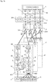
- the figure 1b presents a block diagram of a device according to the invention.
- this architecture ensures the simultaneous operation of the various secondary protocols without almost any influence of one on the other. This guarantees for each protocol, in simultaneous operation with the other protocols, its same performances attainable in the antenna structure of the sensor with the other inactive protocols.
- the architecture of the figure 1b is the evolution of the architecture of a usual secondary radar presented in figure 1a . Part of the description which follows describes the components already present in the usual radar of the figure 1a , the additional elements being highlighted by bolder lines.
- the secondary radar operates in synchronous mode, that is to say it sends an interrogation and waits for a response consistent with it, which allows it to locate by measurement (in azimuth and distance ) and identify (typically by the Mode S protocol address) the target.
- a duplexer 3 performs the RF coupling between the signals transmitted at 1030 MHz and received at 1090 MHz independently for the four diagrams.
- the duplexer 3 comprises a circulator associated with each channel.
- three circulators 311, 313, 314 decouple transmission at 1030 MHz and reception at 1090 MHz respectively from the SUM, CONT_Front and CONT_Back channels.
- listening takes place only in the main lobe of the radar, that is to say on the SUM and DIFF channels after the transmission phase on the SUM and CONT channels.
- the circulator 312 works only in one direction, directing only the reception signals coming from the antenna (the circulator is optional, its use on DIFF is only intended to balance the signals between SUM and DIFF for measurement deviation measurement). In synchronous mode, listening on the LAD channel is only intended to reject responses received with more energy in the LAD diagram than in the SUM diagram.
- Filters 311 ', 313', 314 ' are placed upstream of the circulators on the SUM, CONT_Front and CONT_Back tracks. These filters are mainly used downstream in transmission by filtering the harmonics of the transmitted signals. These same filters are also used in reception to protect frequencies outside the useful band of the secondary radar (that is to say of the order of 1020 to 1100 MHz).
- Spatio-temporal management 5 ensuring real-time management of the associated interrogation and listening periods for the different secondary protocols: IFF, SSR and Mode S.
- This transmission / reception part 4 includes adaptations specific to the invention.
- the SUM 401 transmission chain transmitting at 1030 MHz, incorporates additional filtering 4A, 4B dedicated to the reduction of transmission noise, more particularly to the rejection of parasitic signals at 1090 MHz so that the noise level residual, after coupling 311, or at the noise level of the receiver.
- the transmission chain includes a first amplifier 8 performing a first amplification, it is followed by a first filter 4A. This is followed by a second amplifier 8 ′, a power amplifier, delivering the transmission signal, the latter being followed by the second filter 4B.
- the transmission signal is modulated by a modulator 12 at the frequency of the local oscillator 10, at 1030 MHz.
- a filter 4E is interposed between the oscillator and the modulator, intended to filter the noise at 1090 MHz.
- the received signal is mixed with the signal from the local oscillator by a mixer 11, then filtered by a band-pass filter 13.
- a 4D filter is placed at the output of the CAN 9 ′ to filter the signal at 1030 MHz.
- the DIFF channel operating only in reception comprises a reception chain similar to the reception chain 402 of the SUM channel, in particular it comprises the filtering 4C, 4D filtering the signals transmitted at 1030 MHz. All the channels, send and / or receive SUM, DIFF and CONT work independently of each other.
- the four civil ATC antenna diagrams are treated separately, requiring a 4-channel receiver (or 3-channel if CONT_Front and CONT_Back are added to a CONT channel as usual and illustrated by the figure 1a ).
- Each processing of signal 6, before any decoding of the responses independently adapts its analysis band to the characteristics of the protocol for which it detects the responses.
- This filtering, adapted to each protocol used makes it possible to obtain better performance by reducing the noise level, therefore making it possible to reduce the detection threshold independently for each protocol in order to process the weaker signals.
- the figure 2a illustrates the steps for implementing the invention. At least two steps are necessary for this implementation.
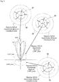
- the figure 3 illustrates an example of operational operation, in accordance with step 23 described above, optimizing ATC surveillance.
- This operating example is illustrated with regard to three aircraft 31, 32, 33 present in the environment of a radar according to the invention.
- Listening to ADS_B squitters is carried out simultaneously on the SUM diagram, on the DIFF diagram, on the CONT_Front diagram and on the CONT_Back diagram of the radar.
- This simultaneous listening makes it possible to avoid the overlapping of the asynchronous responses of targets situated at different deposits and thus to improve their detection and their decoding.
- the aircraft broadcast the ADS-B responses, asynchronous, omnidirectionally 30.
- the response of a first aircraft 31 is thus received on the SUM diagram, the response of a second aircraft 32 is thus received on the CONT_Front diagram and the response from a third aircraft 33 is thus received on the CONT_Back diagram.
- the independent ADS-B reception by antenna diagram makes it possible to ensure the detection, in this example, of these 3 squitters even if they are temporally simultaneous.
- the figure 4d shows the complement of radiation 43 in elevation of the CONT_Back diagram according to the invention.
- the objective is to ensure reception radiation at 1090 MHz even at very high elevations (> 85 °) allowing reception of ADS-B and IFF squitters by increasing the CONT_Back pattern towards high elevations.
- FIGS. 5 and 6 illustrate the advantages of the invention with regard to the sequencing of selective and non-selective transactions. More precisely, the figure 5 presents a usual sequencing with a radar according to the prior art and the figure 6 presents an optimized sequencing with a radar according to the invention, in relation to the second step 22 described with regard to the figure 2a .
- the periods of non-selective “All Call” (AC) transactions and selective “Roll Call” (RC) transactions follow one another according to a timing 51, 52.
- the figure 5 presents four successive periods of order m, m + 1, m + 2 and m + 3 during an illumination time of the antenna lobe of the radar and corresponding successively to the periods AC and RC.
- These AC and RC periods are separated as well as the transmission and reception phases that they contain.
- the figure 8b shows a possible positioning of these radiating elements 81, 82, 83 according to the invention on a conventional ATC secondary antenna 1.
- the “right” 82 and “left” 83 patches are each arranged at a rear end of the plane of the antenna. Patch 81 assigned to the cone of silence is placed in the center, behind the plane of the antenna.
Landscapes
- Engineering & Computer Science (AREA)
- Radar, Positioning & Navigation (AREA)
- Remote Sensing (AREA)
- Physics & Mathematics (AREA)
- Computer Networks & Wireless Communication (AREA)
- General Physics & Mathematics (AREA)
- Electromagnetism (AREA)
- Radar Systems Or Details Thereof (AREA)
- Variable-Direction Aerials And Aerial Arrays (AREA)
Applications Claiming Priority (1)
| Application Number | Priority Date | Filing Date | Title |
|---|---|---|---|
| FR2003806A FR3109451B1 (fr) | 2020-04-16 | 2020-04-16 | Méta Radar Secondaire |
Publications (2)
| Publication Number | Publication Date |
|---|---|
| EP3896484A1 true EP3896484A1 (de) | 2021-10-20 |
| EP3896484B1 EP3896484B1 (de) | 2022-12-28 |
Family
ID=72178664
Family Applications (1)
| Application Number | Title | Priority Date | Filing Date |
|---|---|---|---|
| EP21166308.3A Active EP3896484B1 (de) | 2020-04-16 | 2021-03-31 | Sekundärer meta-radar |
Country Status (9)
| Country | Link |
|---|---|
| US (1) | US11681035B2 (de) |
| EP (1) | EP3896484B1 (de) |
| JP (1) | JP7588023B2 (de) |
| KR (1) | KR20210128352A (de) |
| CN (1) | CN113534134B (de) |
| BR (1) | BR102021007002A2 (de) |
| CA (1) | CA3115159A1 (de) |
| ES (1) | ES2938853T3 (de) |
| FR (1) | FR3109451B1 (de) |
Families Citing this family (2)
| Publication number | Priority date | Publication date | Assignee | Title |
|---|---|---|---|---|
| CN115862386B (zh) * | 2022-11-11 | 2025-08-19 | 中国航空工业集团公司西安飞行自动控制研究所 | 一种探通一体化的机载空中交通监视系统及方法 |
| FR3144667B1 (fr) | 2022-12-29 | 2025-01-10 | Thales Sa | Chaîne de réception IFF/ADS-B |
Citations (3)
| Publication number | Priority date | Publication date | Assignee | Title |
|---|---|---|---|---|
| FR2658967A1 (fr) | 1990-02-28 | 1991-08-30 | Dassault Avions | Dispositif de couplage a une antenne commune d'au moins deux appareils emetteurs et/ou recepteurs. |
| FR3019905A1 (fr) | 2014-04-11 | 2015-10-16 | Thales Sa | Radar secondaire de surveillance a grande cadence de rafraichissement |
| EP3273262A1 (de) * | 2016-07-23 | 2018-01-24 | HENSOLDT Sensors GmbH | Sekundärer monopuls-überwachungsradar |
Family Cites Families (8)
| Publication number | Priority date | Publication date | Assignee | Title |
|---|---|---|---|---|
| JP2011158452A (ja) * | 2010-02-04 | 2011-08-18 | Toshiba Corp | 二次監視レーダ |
| CN103364780B (zh) * | 2013-07-29 | 2015-12-09 | 四川九洲空管科技有限责任公司 | 机载二次雷达询问应答一体化设备 |
| FR3018923B1 (fr) * | 2014-03-20 | 2016-03-04 | Thales Sa | Radar secondaire bi-fonction, et systeme radar comportant un tel radar |
| FR3049353B1 (fr) * | 2016-03-25 | 2018-06-22 | Thales | Radar secondaire apte a detecter des cibles en haute elevation |
| FR3075398B1 (fr) | 2017-12-19 | 2020-01-10 | Thales | Procede de mesure de diagrammes d antenne d un radar secondaire et radar secondaire mettant en oeuvre un tel procede |
| CN108761409B (zh) * | 2018-07-19 | 2022-03-25 | 电子科技大学 | 一种二次雷达信号的产生及测试方法 |
| FR3085487B1 (fr) | 2018-08-30 | 2020-07-31 | Thales Sa | Procede de caracterisation de la densite d'interrogations et de reponses mode s et radar secondaire mettant en oeuvre un tel procede |
| FR3103568B1 (fr) * | 2019-11-25 | 2021-12-03 | Thales Sa | Procede de detection de conflits de code ii/si d'identification de radar mode s avec des radars environnants, et radar secondaire mettant en oeuvre un tel procede |
-
2020
- 2020-04-16 FR FR2003806A patent/FR3109451B1/fr not_active Expired - Fee Related
-
2021
- 2021-03-31 ES ES21166308T patent/ES2938853T3/es active Active
- 2021-03-31 EP EP21166308.3A patent/EP3896484B1/de active Active
- 2021-04-05 US US17/222,766 patent/US11681035B2/en active Active
- 2021-04-06 JP JP2021064569A patent/JP7588023B2/ja active Active
- 2021-04-13 BR BR102021007002-1A patent/BR102021007002A2/pt unknown
- 2021-04-14 CA CA3115159A patent/CA3115159A1/en active Pending
- 2021-04-14 KR KR1020210048820A patent/KR20210128352A/ko active Pending
- 2021-04-15 CN CN202110404662.5A patent/CN113534134B/zh active Active
Patent Citations (3)
| Publication number | Priority date | Publication date | Assignee | Title |
|---|---|---|---|---|
| FR2658967A1 (fr) | 1990-02-28 | 1991-08-30 | Dassault Avions | Dispositif de couplage a une antenne commune d'au moins deux appareils emetteurs et/ou recepteurs. |
| FR3019905A1 (fr) | 2014-04-11 | 2015-10-16 | Thales Sa | Radar secondaire de surveillance a grande cadence de rafraichissement |
| EP3273262A1 (de) * | 2016-07-23 | 2018-01-24 | HENSOLDT Sensors GmbH | Sekundärer monopuls-überwachungsradar |
Non-Patent Citations (1)
| Title |
|---|
| MARIANO P ET AL: "Multi-functional compact radar for surveillance in terminal areas (RAMS): New solution for radar surveillance in terminal approach area", 2014 TYRRHENIAN INTERNATIONAL WORKSHOP ON DIGITAL COMMUNICATIONS - ENHANCED SURVEILLANCE OF AIRCRAFT AND VEHICLES (TIWDC/ESAV), IEEE, 15 September 2014 (2014-09-15), pages 56 - 61, XP032677366, DOI: 10.1109/TIWDC-ESAV.2014.6945448 * |
Also Published As
| Publication number | Publication date |
|---|---|
| US11681035B2 (en) | 2023-06-20 |
| FR3109451B1 (fr) | 2022-04-08 |
| CN113534134B (zh) | 2026-05-26 |
| ES2938853T3 (es) | 2023-04-17 |
| BR102021007002A2 (pt) | 2021-10-26 |
| US20210325527A1 (en) | 2021-10-21 |
| JP2021170000A (ja) | 2021-10-28 |
| CN113534134A (zh) | 2021-10-22 |
| EP3896484B1 (de) | 2022-12-28 |
| JP7588023B2 (ja) | 2024-11-21 |
| KR20210128352A (ko) | 2021-10-26 |
| CA3115159A1 (en) | 2021-10-16 |
| FR3109451A1 (fr) | 2021-10-22 |
Similar Documents
| Publication | Publication Date | Title |
|---|---|---|
| EP2431762B1 (de) | Verfahren zur Verlängerung der Beleuchtungszeit von Zielen durch einen Sekundärenradar | |
| US9658325B2 (en) | Secondary surveillance radar signals as primary surveillance radar | |
| CN102227647B (zh) | 用于利用以准动态或动态方式对要监控的空间进行分区化来接收二次雷达信号的设备及用于此的方法 | |
| EP3945344B1 (de) | Sekundärradar zur verbesserung der flugsicherheit durch erkennung von ads-b mit sehr grosser reichweite | |
| EP3844529B1 (de) | Verfahren zur charakterisierung der dichte von modus-s-abfragen und -antworten sowie sekundärradar zur durchführung eines solchen verfahrens | |
| FR3082949A1 (fr) | Procede de detection et de localisation de fausses cibles ads-b et systeme de radars secondaires mettant en oeuvre un tel procede | |
| FR2688316A1 (fr) | Appareil permettant d'etendre la portee d'utilisation d'un radar de surveillance secondaire passif a l'aide d'antennes directives commutees en synchronisme avec le faisceau tournant d'un radar de surveillance secondaire. | |
| EP3896484B1 (de) | Sekundärer meta-radar | |
| EP1354219B1 (de) | System zur überwachung von reifen eines fahrzeugs mit einer einrichtung zum automatischen finden von radsendern | |
| EP3223032B1 (de) | Sekundärradar für die erfassung von zielen in grosser höhe | |
| EP2922144B1 (de) | Doppelfunktions-Sekundärradar und Radarsystem, das einen solchen Radar umfasst | |
| EP2930531B1 (de) | Sekundärradar zur überwachung mit grosser refresh-rate | |
| FR3090122A1 (fr) | Procédé de mesure de précision azimut et de diagrammes du lobe principal d’antenne d’un radar secondaire, et radar mettant en œuvre un tel procédé | |
| EP3825726A1 (de) | Verfahren zur erkennung von ii/si-identifizierungscode konflikten des radar-modus s und umliegenden radargeräten, und sekundärradar zur umsetzung dieses verfahrens | |
| EP3771926A1 (de) | Sekundärradar mit adaptiver steuerung des mode-s-strahls durch ein flugzeug | |
| EP3321711B1 (de) | Aufnahmevorrichtung für antenne mit elektronischer strahlschwenkung, die im resm- und radarmodus arbeiten kann, und mit dieser vorrichtung ausgestatteter radar | |
| EP3111247B1 (de) | Zur ausrüstung eines küstenüberwachungssystems geeignete radarvorrichtung und küstenüberwachungssystem mit solch einer vorrichtung | |
| Navrátil et al. | Utilization of terrestrial navigation signals for passive radar | |
| FR2644898A1 (fr) | Procede de telesurveillance des elements rayonnants d'antenne d'un radar secondaire de surveillance et dispositif pour sa mise en oeuvre | |
| WO2009013314A1 (fr) | Procede d'interception de signaux radioelectriques et recepteur compact large bande instantanee | |
| HK40051823A (zh) | 辅助元雷达 | |
| WO2025141134A1 (fr) | Système de localisation relative des plateformes d'un essaim de plateformes en deplacement | |
| FR2903194A1 (fr) | Procede et dispositif de detection de cibles comportant des moyens d'auto-protection susceptibles d'emettre des ondes electromagnetiques |
Legal Events
| Date | Code | Title | Description |
|---|---|---|---|
| PUAI | Public reference made under article 153(3) epc to a published international application that has entered the european phase |
Free format text: ORIGINAL CODE: 0009012 |
|
| STAA | Information on the status of an ep patent application or granted ep patent |
Free format text: STATUS: THE APPLICATION HAS BEEN PUBLISHED |
|
| AK | Designated contracting states |
Kind code of ref document: A1 Designated state(s): AL AT BE BG CH CY CZ DE DK EE ES FI FR GB GR HR HU IE IS IT LI LT LU LV MC MK MT NL NO PL PT RO RS SE SI SK SM TR |
|
| B565 | Issuance of search results under rule 164(2) epc |
Effective date: 20210914 |
|
| REG | Reference to a national code |
Ref country code: HK Ref legal event code: DE Ref document number: 40051823 Country of ref document: HK |
|
| STAA | Information on the status of an ep patent application or granted ep patent |
Free format text: STATUS: REQUEST FOR EXAMINATION WAS MADE |
|
| 17P | Request for examination filed |
Effective date: 20220308 |
|
| RBV | Designated contracting states (corrected) |
Designated state(s): AL AT BE BG CH CY CZ DE DK EE ES FI FR GB GR HR HU IE IS IT LI LT LU LV MC MK MT NL NO PL PT RO RS SE SI SK SM TR |
|
| GRAP | Despatch of communication of intention to grant a patent |
Free format text: ORIGINAL CODE: EPIDOSNIGR1 |
|
| STAA | Information on the status of an ep patent application or granted ep patent |
Free format text: STATUS: GRANT OF PATENT IS INTENDED |
|
| RIC1 | Information provided on ipc code assigned before grant |
Ipc: G01S 7/28 20060101ALI20220818BHEP Ipc: G01S 7/03 20060101ALI20220818BHEP Ipc: G01S 13/91 20060101ALI20220818BHEP Ipc: G01S 13/76 20060101ALI20220818BHEP Ipc: G01S 13/78 20060101AFI20220818BHEP |
|
| INTG | Intention to grant announced |
Effective date: 20220919 |
|
| GRAS | Grant fee paid |
Free format text: ORIGINAL CODE: EPIDOSNIGR3 |
|
| GRAA | (expected) grant |
Free format text: ORIGINAL CODE: 0009210 |
|
| STAA | Information on the status of an ep patent application or granted ep patent |
Free format text: STATUS: THE PATENT HAS BEEN GRANTED |
|
| AK | Designated contracting states |
Kind code of ref document: B1 Designated state(s): AL AT BE BG CH CY CZ DE DK EE ES FI FR GB GR HR HU IE IS IT LI LT LU LV MC MK MT NL NO PL PT RO RS SE SI SK SM TR |
|
| REG | Reference to a national code |
Ref country code: GB Ref legal event code: FG4D Free format text: NOT ENGLISH |
|
| REG | Reference to a national code |
Ref country code: CH Ref legal event code: EP |
|
| REG | Reference to a national code |
Ref country code: DE Ref legal event code: R096 Ref document number: 602021001074 Country of ref document: DE |
|
| REG | Reference to a national code |
Ref country code: AT Ref legal event code: REF Ref document number: 1540827 Country of ref document: AT Kind code of ref document: T Effective date: 20230115 |
|
| REG | Reference to a national code |
Ref country code: IE Ref legal event code: FG4D Free format text: LANGUAGE OF EP DOCUMENT: FRENCH |
|
| REG | Reference to a national code |
Ref country code: LT Ref legal event code: MG9D |
|
| REG | Reference to a national code |
Ref country code: ES Ref legal event code: FG2A Ref document number: 2938853 Country of ref document: ES Kind code of ref document: T3 Effective date: 20230417 |
|
| PG25 | Lapsed in a contracting state [announced via postgrant information from national office to epo] |
Ref country code: SE Free format text: LAPSE BECAUSE OF FAILURE TO SUBMIT A TRANSLATION OF THE DESCRIPTION OR TO PAY THE FEE WITHIN THE PRESCRIBED TIME-LIMIT Effective date: 20221228 Ref country code: NO Free format text: LAPSE BECAUSE OF FAILURE TO SUBMIT A TRANSLATION OF THE DESCRIPTION OR TO PAY THE FEE WITHIN THE PRESCRIBED TIME-LIMIT Effective date: 20230328 Ref country code: LT Free format text: LAPSE BECAUSE OF FAILURE TO SUBMIT A TRANSLATION OF THE DESCRIPTION OR TO PAY THE FEE WITHIN THE PRESCRIBED TIME-LIMIT Effective date: 20221228 Ref country code: FI Free format text: LAPSE BECAUSE OF FAILURE TO SUBMIT A TRANSLATION OF THE DESCRIPTION OR TO PAY THE FEE WITHIN THE PRESCRIBED TIME-LIMIT Effective date: 20221228 |
|
| REG | Reference to a national code |
Ref country code: NL Ref legal event code: MP Effective date: 20221228 |
|
| REG | Reference to a national code |
Ref country code: AT Ref legal event code: MK05 Ref document number: 1540827 Country of ref document: AT Kind code of ref document: T Effective date: 20221228 |
|
| PG25 | Lapsed in a contracting state [announced via postgrant information from national office to epo] |
Ref country code: RS Free format text: LAPSE BECAUSE OF FAILURE TO SUBMIT A TRANSLATION OF THE DESCRIPTION OR TO PAY THE FEE WITHIN THE PRESCRIBED TIME-LIMIT Effective date: 20221228 Ref country code: LV Free format text: LAPSE BECAUSE OF FAILURE TO SUBMIT A TRANSLATION OF THE DESCRIPTION OR TO PAY THE FEE WITHIN THE PRESCRIBED TIME-LIMIT Effective date: 20221228 Ref country code: HR Free format text: LAPSE BECAUSE OF FAILURE TO SUBMIT A TRANSLATION OF THE DESCRIPTION OR TO PAY THE FEE WITHIN THE PRESCRIBED TIME-LIMIT Effective date: 20221228 Ref country code: GR Free format text: LAPSE BECAUSE OF FAILURE TO SUBMIT A TRANSLATION OF THE DESCRIPTION OR TO PAY THE FEE WITHIN THE PRESCRIBED TIME-LIMIT Effective date: 20230329 |
|
| PG25 | Lapsed in a contracting state [announced via postgrant information from national office to epo] |
Ref country code: NL Free format text: LAPSE BECAUSE OF FAILURE TO SUBMIT A TRANSLATION OF THE DESCRIPTION OR TO PAY THE FEE WITHIN THE PRESCRIBED TIME-LIMIT Effective date: 20221228 |
|
| PG25 | Lapsed in a contracting state [announced via postgrant information from national office to epo] |
Ref country code: SM Free format text: LAPSE BECAUSE OF FAILURE TO SUBMIT A TRANSLATION OF THE DESCRIPTION OR TO PAY THE FEE WITHIN THE PRESCRIBED TIME-LIMIT Effective date: 20221228 Ref country code: RO Free format text: LAPSE BECAUSE OF FAILURE TO SUBMIT A TRANSLATION OF THE DESCRIPTION OR TO PAY THE FEE WITHIN THE PRESCRIBED TIME-LIMIT Effective date: 20221228 Ref country code: PT Free format text: LAPSE BECAUSE OF FAILURE TO SUBMIT A TRANSLATION OF THE DESCRIPTION OR TO PAY THE FEE WITHIN THE PRESCRIBED TIME-LIMIT Effective date: 20230428 Ref country code: EE Free format text: LAPSE BECAUSE OF FAILURE TO SUBMIT A TRANSLATION OF THE DESCRIPTION OR TO PAY THE FEE WITHIN THE PRESCRIBED TIME-LIMIT Effective date: 20221228 Ref country code: AT Free format text: LAPSE BECAUSE OF FAILURE TO SUBMIT A TRANSLATION OF THE DESCRIPTION OR TO PAY THE FEE WITHIN THE PRESCRIBED TIME-LIMIT Effective date: 20221228 |
|
| PG25 | Lapsed in a contracting state [announced via postgrant information from national office to epo] |
Ref country code: SK Free format text: LAPSE BECAUSE OF FAILURE TO SUBMIT A TRANSLATION OF THE DESCRIPTION OR TO PAY THE FEE WITHIN THE PRESCRIBED TIME-LIMIT Effective date: 20221228 Ref country code: PL Free format text: LAPSE BECAUSE OF FAILURE TO SUBMIT A TRANSLATION OF THE DESCRIPTION OR TO PAY THE FEE WITHIN THE PRESCRIBED TIME-LIMIT Effective date: 20221228 Ref country code: IS Free format text: LAPSE BECAUSE OF FAILURE TO SUBMIT A TRANSLATION OF THE DESCRIPTION OR TO PAY THE FEE WITHIN THE PRESCRIBED TIME-LIMIT Effective date: 20230428 Ref country code: AL Free format text: LAPSE BECAUSE OF FAILURE TO SUBMIT A TRANSLATION OF THE DESCRIPTION OR TO PAY THE FEE WITHIN THE PRESCRIBED TIME-LIMIT Effective date: 20221228 |
|
| REG | Reference to a national code |
Ref country code: DE Ref legal event code: R097 Ref document number: 602021001074 Country of ref document: DE |
|
| PG25 | Lapsed in a contracting state [announced via postgrant information from national office to epo] |
Ref country code: MC Free format text: LAPSE BECAUSE OF FAILURE TO SUBMIT A TRANSLATION OF THE DESCRIPTION OR TO PAY THE FEE WITHIN THE PRESCRIBED TIME-LIMIT Effective date: 20221228 Ref country code: DK Free format text: LAPSE BECAUSE OF FAILURE TO SUBMIT A TRANSLATION OF THE DESCRIPTION OR TO PAY THE FEE WITHIN THE PRESCRIBED TIME-LIMIT Effective date: 20221228 |
|
| PLBE | No opposition filed within time limit |
Free format text: ORIGINAL CODE: 0009261 |
|
| STAA | Information on the status of an ep patent application or granted ep patent |
Free format text: STATUS: NO OPPOSITION FILED WITHIN TIME LIMIT |
|
| 26N | No opposition filed |
Effective date: 20230929 |
|
| PG25 | Lapsed in a contracting state [announced via postgrant information from national office to epo] |
Ref country code: LU Free format text: LAPSE BECAUSE OF NON-PAYMENT OF DUE FEES Effective date: 20230331 |
|
| REG | Reference to a national code |
Ref country code: IE Ref legal event code: MM4A |
|
| PG25 | Lapsed in a contracting state [announced via postgrant information from national office to epo] |
Ref country code: SI Free format text: LAPSE BECAUSE OF FAILURE TO SUBMIT A TRANSLATION OF THE DESCRIPTION OR TO PAY THE FEE WITHIN THE PRESCRIBED TIME-LIMIT Effective date: 20221228 Ref country code: IE Free format text: LAPSE BECAUSE OF NON-PAYMENT OF DUE FEES Effective date: 20230331 |
|
| REG | Reference to a national code |
Ref country code: CH Ref legal event code: PL |
|
| PG25 | Lapsed in a contracting state [announced via postgrant information from national office to epo] |
Ref country code: BG Free format text: LAPSE BECAUSE OF FAILURE TO SUBMIT A TRANSLATION OF THE DESCRIPTION OR TO PAY THE FEE WITHIN THE PRESCRIBED TIME-LIMIT Effective date: 20221228 |
|
| PG25 | Lapsed in a contracting state [announced via postgrant information from national office to epo] |
Ref country code: BG Free format text: LAPSE BECAUSE OF FAILURE TO SUBMIT A TRANSLATION OF THE DESCRIPTION OR TO PAY THE FEE WITHIN THE PRESCRIBED TIME-LIMIT Effective date: 20221228 |
|
| PG25 | Lapsed in a contracting state [announced via postgrant information from national office to epo] |
Ref country code: CH Free format text: LAPSE BECAUSE OF NON-PAYMENT OF DUE FEES Effective date: 20240331 |
|
| PG25 | Lapsed in a contracting state [announced via postgrant information from national office to epo] |
Ref country code: CY Free format text: LAPSE BECAUSE OF FAILURE TO SUBMIT A TRANSLATION OF THE DESCRIPTION OR TO PAY THE FEE WITHIN THE PRESCRIBED TIME-LIMIT; INVALID AB INITIO Effective date: 20210331 |
|
| PG25 | Lapsed in a contracting state [announced via postgrant information from national office to epo] |
Ref country code: HU Free format text: LAPSE BECAUSE OF FAILURE TO SUBMIT A TRANSLATION OF THE DESCRIPTION OR TO PAY THE FEE WITHIN THE PRESCRIBED TIME-LIMIT; INVALID AB INITIO Effective date: 20210331 |
|
| PG25 | Lapsed in a contracting state [announced via postgrant information from national office to epo] |
Ref country code: TR Free format text: LAPSE BECAUSE OF FAILURE TO SUBMIT A TRANSLATION OF THE DESCRIPTION OR TO PAY THE FEE WITHIN THE PRESCRIBED TIME-LIMIT Effective date: 20221228 |
|
| PGFP | Annual fee paid to national office [announced via postgrant information from national office to epo] |
Ref country code: GB Payment date: 20260223 Year of fee payment: 6 |
|
| PGFP | Annual fee paid to national office [announced via postgrant information from national office to epo] |
Ref country code: DE Payment date: 20260218 Year of fee payment: 6 |
|
| PGFP | Annual fee paid to national office [announced via postgrant information from national office to epo] |
Ref country code: BE Payment date: 20260216 Year of fee payment: 6 Ref country code: IT Payment date: 20260226 Year of fee payment: 6 |
|
| PGFP | Annual fee paid to national office [announced via postgrant information from national office to epo] |
Ref country code: FR Payment date: 20260223 Year of fee payment: 6 |
|
| PGFP | Annual fee paid to national office [announced via postgrant information from national office to epo] |
Ref country code: CZ Payment date: 20260323 Year of fee payment: 6 |
|
| PG25 | Lapsed in a contracting state [announced via postgrant information from national office to epo] |
Ref country code: CH Free format text: THE PATENT HAS BEEN ANNULLED BY A DECISION OF A NATIONAL AUTHORITY Effective date: 20240331 |
|
| PGFP | Annual fee paid to national office [announced via postgrant information from national office to epo] |
Ref country code: ES Payment date: 20260409 Year of fee payment: 6 |
|
| PG25 | Lapsed in a contracting state [announced via postgrant information from national office to epo] |
Ref country code: MT Free format text: LAPSE BECAUSE OF NON-PAYMENT OF DUE FEES Effective date: 20230331 |