EP3896540A1 - Machine de traitement des pièces métalliques - Google Patents
Machine de traitement des pièces métalliques Download PDFInfo
- Publication number
- EP3896540A1 EP3896540A1 EP20169804.0A EP20169804A EP3896540A1 EP 3896540 A1 EP3896540 A1 EP 3896540A1 EP 20169804 A EP20169804 A EP 20169804A EP 3896540 A1 EP3896540 A1 EP 3896540A1
- Authority
- EP
- European Patent Office
- Prior art keywords
- display
- machine
- elevations
- operator
- machine according
- Prior art date
- Legal status (The legal status is an assumption and is not a legal conclusion. Google has not performed a legal analysis and makes no representation as to the accuracy of the status listed.)
- Withdrawn
Links
Images


Classifications
-
- G—PHYSICS
- G05—CONTROLLING; REGULATING
- G05B—CONTROL OR REGULATING SYSTEMS IN GENERAL; FUNCTIONAL ELEMENTS OF SUCH SYSTEMS; MONITORING OR TESTING ARRANGEMENTS FOR SUCH SYSTEMS OR ELEMENTS
- G05B19/00—Program-control systems
- G05B19/02—Program-control systems electric
- G05B19/18—Numerical control [NC], i.e. automatically operating machines, in particular machine tools, e.g. in a manufacturing environment, so as to execute positioning, movement or co-ordinated operations by means of program data in numerical form
- G05B19/409—Numerical control [NC], i.e. automatically operating machines, in particular machine tools, e.g. in a manufacturing environment, so as to execute positioning, movement or co-ordinated operations by means of program data in numerical form characterised by using manual data input [MDI] or by using control panel, e.g. controlling functions with the panel; characterised by control panel details or by setting parameters
-
- G—PHYSICS
- G06—COMPUTING OR CALCULATING; COUNTING
- G06F—ELECTRIC DIGITAL DATA PROCESSING
- G06F3/00—Input arrangements for transferring data to be processed into a form capable of being handled by the computer; Output arrangements for transferring data from processing unit to output unit, e.g. interface arrangements
- G06F3/01—Input arrangements or combined input and output arrangements for interaction between user and computer
- G06F3/016—Input arrangements with force or tactile feedback as computer generated output to the user
-
- G—PHYSICS
- G06—COMPUTING OR CALCULATING; COUNTING
- G06F—ELECTRIC DIGITAL DATA PROCESSING
- G06F3/00—Input arrangements for transferring data to be processed into a form capable of being handled by the computer; Output arrangements for transferring data from processing unit to output unit, e.g. interface arrangements
- G06F3/01—Input arrangements or combined input and output arrangements for interaction between user and computer
- G06F3/048—Interaction techniques based on graphical user interfaces [GUI]
- G06F3/0487—Interaction techniques based on graphical user interfaces [GUI] using specific features provided by the input device, e.g. functions controlled by the rotation of a mouse with dual sensing arrangements, or of the nature of the input device, e.g. tap gestures based on pressure sensed by a digitiser
- G06F3/0488—Interaction techniques based on graphical user interfaces [GUI] using specific features provided by the input device, e.g. functions controlled by the rotation of a mouse with dual sensing arrangements, or of the nature of the input device, e.g. tap gestures based on pressure sensed by a digitiser using a touch-screen or digitiser, e.g. input of commands through traced gestures
- G06F3/04886—Interaction techniques based on graphical user interfaces [GUI] using specific features provided by the input device, e.g. functions controlled by the rotation of a mouse with dual sensing arrangements, or of the nature of the input device, e.g. tap gestures based on pressure sensed by a digitiser using a touch-screen or digitiser, e.g. input of commands through traced gestures by partitioning the display area of the touch-screen or the surface of the digitising tablet into independently controllable areas, e.g. virtual keyboards or menus
-
- G—PHYSICS
- G05—CONTROLLING; REGULATING
- G05B—CONTROL OR REGULATING SYSTEMS IN GENERAL; FUNCTIONAL ELEMENTS OF SUCH SYSTEMS; MONITORING OR TESTING ARRANGEMENTS FOR SUCH SYSTEMS OR ELEMENTS
- G05B2219/00—Program-control systems
- G05B2219/30—Nc systems
- G05B2219/36—Nc in input of data, input key till input tape
- G05B2219/36168—Touchscreen
-
- G—PHYSICS
- G06—COMPUTING OR CALCULATING; COUNTING
- G06F—ELECTRIC DIGITAL DATA PROCESSING
- G06F2203/00—Indexing scheme relating to G06F3/00 - G06F3/048
- G06F2203/048—Indexing scheme relating to G06F3/048
- G06F2203/04809—Textured surface identifying touch areas, e.g. overlay structure for a virtual keyboard
Definitions
- the invention relates to a machine for processing metallic workpieces, in particular a bending machine or a cutting machine, such as. B. a press brake, a plasma cutting machine or a laser cutting machine.
- touch-sensitive displays that are currently used in machines for processing metallic workpieces only give the operator visual feedback about the location of the graphic control elements, so that the operator always has to look at the display surface when operating the display.
- the document shows WO 2009/037379 A1 a device for generating an electrosensory perception on a finger of a user by a capacitive coupling via an insulator which is formed between a conductive electrode and the finger.
- the pamphlet US 2014/0354570 A1 discloses a touch-sensitive display in which haptic feedback is given to a part of the body that is in contact with the display via an electronic circuit.
- the object of the invention is to create a machine for processing metallic workpieces, the operation of which is improved via a display with a touch-sensitive display surface.
- the machine according to the invention is used for processing metallic workpieces and includes a display that includes a touch-sensitive display surface for the variable display of graphic operating elements, which can be actuated by an operator using his hand (ie his fingers) by touching them on the display surface in order to thereby issue commands to operate the machine.
- the display is set up for actuation of the graphic operating elements by touching the operator with and without gloves.
- technologies known per se can optionally be used, which enable operation with and without gloves.
- the pressure exerted by the operator on the display can be detected by approaching two opposing electrodes and the associated change in capacitance.
- the display can also be designed in this way, if necessary be that it is only set up for actuation of the graphic control elements by touching the operator without gloves.
- one or more means for the variable formation of elevations in areas of the display area on which there are graphic control elements are also provided, the elevations having a respective height of at least 1 mm on the display area.
- the height of an elevation is to be understood as the highest point of the corresponding elevation in comparison to an area of the display area without an elevation.
- the minimum height of the elevation and also the maximum height mentioned below refer to a static state of the elevation, i.e. a state in which the height of the elevation is currently not changed.
- the elevation can be designed as a bulge, for example.
- the display according to the invention has the advantage that a user is given haptic feedback about the position of corresponding graphic control elements on the touch-sensitive display surface through sufficiently high elevations of at least 1 mm. He does not have to constantly look at the display when operating the machine, but can also feel the corresponding operating elements. This simplifies the operation.
- the operator preferably has the option of operating the controls both with and without gloves.
- the elevations each have a height of at most 5 mm, which is a sufficient height to feel the elevations.
- the elevations in the display area each have an area of at least 200 mm 2 and preferably of at least 225 mm 2 .
- the respective elevations preferably have an area of at most 2500 mm 2 and in particular at most 2200 mm 2 . These area sizes ensure that the control elements can still be easily operated individually.
- the elevations each have the shape of a rectangle and in particular the shape of a square.
- the length of a respective edge of the rectangle is preferably at least 15 mm.
- the or each means for the variable formation of the elevations is provided with a device for haptic feedback which emits a tactile signal when a graphic control element is actuated.
- the tactile signal is generated by varying the height of the elevation in the area of the actuated graphic control element, in particular in the form of a short oscillation pulse. This has the advantage that the operator feels the acknowledgment or confirmation of his input.
- the elevation can temporarily fall below the minimum height of 1 mm.
- the height of the elevation can change periodically at a high frequency, whereby the operator is given confirmation in the form of a vibration. If necessary, it is also possible that different types of confirmations, for example via different vibration frequencies, are reported back to the operator. For example, positive feedback can be given if the action linked to the operating element is triggered by its actuation. In the same way, negative feedback can be given if, for certain reasons, the action linked to the control element cannot currently be carried out, for example because another control element must first be actuated.
- the or each means for the variable formation of elevations comprises an array, integrated in the display area, of a plurality of flexible chambers, which are preferably located on the entire display area are distributed.
- the respective chambers can be filled with a fluid and their filling state can be changed with an actuator in order to thereby variably form the elevations in the area of the operating elements.
- the chambers can be filled pneumatically with air or hydraulically with a liquid. With this variant, the elevations in the area of the graphic control elements can be generated very easily.
- the or each means for the variable formation of elevations comprises an array, integrated in the display area, of a multiplicity of piezo elements which, for example, consist of a ceramic and are preferably in turn distributed over the entire display area.
- the deformation of the respective piezo elements can be changed by applying an electrical voltage by means of a voltage source, as a result of which the elevations in the area of the graphic control elements can be formed in a variable manner.
- the or each means for the variable formation of elevations is also set up to detect the actuation of the graphic control elements by touching the operator.
- a pressure sensor system for measuring the fluid pressure in the respective chambers is provided for this array in order to activate a graphic control element by touching the operator via a To detect rise in the fluid pressure of one or more chambers at the location of the graphic control element.
- the display is designed in such a way that when the graphical operating element is actuated, the strength of the pressure exerted by the operator is also detected via the measured fluid pressure, the operating command entered by the operator depending on the strength of the pressure.
- the operator can use a single control element to give different control commands by varying the touch pressure specify. For example, he can specify a numerical value to be entered via the touch pressure, which he would otherwise enter via a numeric keypad.
- a device for voltage measurement is provided for this array in order to activate a graphic control element by touching the operator via the occurrence of an electrical voltage on one or more piezo elements at the location to detect the graphic control element.
- the display and preferably the or each means for the variable formation of elevations is set up to detect the pressure exerted by the operator on the display surface when a graphic control element is actuated in order to trigger different actions depending on the detected pressure. For example, when the pressure is below a certain threshold, the operating action provided for the operating element can be triggered, whereas when the pressure is higher, a context menu is shown on the display.
- the display of the machine according to the invention is attached to a part of the machine in which the machining of the metallic workpieces takes place when the machine is in operation.
- the display it is also possible for the display to be set up at a location where it is not attached to a part of the machine in which the processing of the metallic workpieces takes place when the machine is in operation.
- the display can be part of a console that can be moved separately from the rest of the machine. The display is only connected to the machine in terms of communication technology or electrically.
- the invention relates to a display for such a machine, the display being a touch-sensitive display surface includes variable display of graphical operating elements, which can be actuated by touching them on the display surface by an operator using his hand in order to thereby enter commands for operating the machine.
- the display has one or more means for the variable formation of elevations in areas of the display surface on which there are graphic operating elements, the elevations having a respective height of at least 1 mm on the display surface.
- the display is thus set up to work as a display for the machine according to the invention.
- this display is also set up to work as a display for a machine in accordance with one or more of the preferred embodiments described above.
- features of the preferred embodiments of the machine described above can be implemented in the display of the machine, provided the features relate to the display.
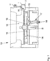
- FIG. 1 An embodiment of the invention is described below using a machine for processing metallic workpieces in the form of a press brake. Such a machine is in Fig. 1 and denoted there by reference numeral 10. Nevertheless, the invention can also be used for other machines for processing metallic workpieces. This includes in particular all types of bending machines and cutting machines, such as. B. laser cutting machines or plasma cutting machines.
- the machine 10 shown is designed as a press brake and comprises, in a manner known per se, an upper beam 12 and a lower beam 13, to which the respective bending tools 14 are attached.
- An operator B pushes a sheet metal to be bent between the tools 14 up to the corresponding stop fingers 16 and can then start and control the bending process.
- a control panel 17 with foot pedals 18 on the one hand.
- a display 1 with a touch-sensitive display surface 2 is available to him, which is attached to the right-hand side of the machine 10 via an articulation mechanism 11 made up of several mutually articulated arms.
- This display represents a component of the machine 10 that is essential to the invention.
- the operator B can give a large number of operating commands to the machine 10 or a corresponding control device of the machine 10.
- graphical operating elements are displayed on the display surface 2 of the display 1, with in Fig. 1 by way of example only a single graphic operating element BE is reproduced as a hatched rectangle.
- the display In a conventional machine, the display is designed in such a way that it can only be operated without gloves by direct contact with the operator's skin. Often, however, it is desirable that the operator can also operate the display with gloves, since he usually wears gloves when he is working on the machine and he does not want to take them off to perform an operator action on the display. Furthermore, the operator can only perceive the position of graphic control elements on a display of a conventional machine visually and not haptically.
- the display 1 can be part of a movable console that can be positioned separately from the rest of the machine.
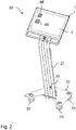
- Fig. 2 shows such a movable console.
- This console is denoted by the reference number 20 and comprises a vertical support 21, at the upper end of which the display 1 with the touch-sensitive display surface 2 is attached. To illustrate this, two graphic operating elements BE are shown on the display area.
- the lower end of the carrier 21 is connected to a movable base 22 on which there are four lockable rollers 23, via which the movable console 20 can be positioned at any point in the vicinity of the machine 10.
- the console 20 is connected to the machine electrically and in terms of communication technology only via cables (not shown).
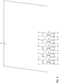
- FIG. 4 shows a perspective detailed view of the display 1 from FIG Fig. 1 and Fig. 2 .
- the lower edge of the display is designated with reference number 1a, the right edge with reference number 1b, the left edge with reference number 1c and the upper edge with reference number 1d.
- the display area 2 contains an uppermost layer 3, which is shown for clarity at a distance from the rest of the display area.
- This layer is formed from flexible synthetic material and comprises an array of a multiplicity of chambers which, in the embodiment described here, can be filled and emptied hydraulically with a liquid. These chambers are partly from the view of the Fig. 4 can be seen and denoted there by reference numeral 7.
- Fig. 4 shows only the layer 3 of the display area 2. Examples are shown in FIG Fig. 4 also only five chambers in a lower row of layer 3 are shown. However, the chambers are distributed as an array at regular intervals over the entire layer 3.
- FIG. 4 The chambers 7 shown are shown in the fully filled state, with the result that elevations 8 are formed by the chambers.
- the elevations 8 are only ever formed at positions at which graphic operating elements BE are also located on the display surface 2.
- the operating elements displayed and their positions are variable depending on the menu page called up on the user interface shown on the display. Depending on the currently displayed graphic operating elements, those chambers are always filled whose positions correspond to the positions of the graphic operating elements.
- the individual chambers 7 are designed in such a way that when they are fully filled they form an elevation of at least 1 mm in relation to a surface area of the display area on which there is no operating element and a corresponding chamber is not filled.
- each individual chamber is connected to a line 4, which leads to a respective actuator 5 and a respective pressure sensor 6, which are only shown schematically and are integrated in the display 1.
- the entirety of the actuators 6 represents an embodiment of an actuator system within the meaning of the claims.
- the entirety of the pressure sensors 6 represents an embodiment of a pressure sensor system within the meaning of the claims.
- the actuator 5 is designed as a pump with a valve connected to it and it is connected to a liquid reservoir, not shown, which is provided in the display.
- the actuator 5 causes the chamber 7 to be filled with liquid from the liquid reservoir via the line 4.
- the actuator effects a corresponding emptying of the chamber 7 by discharging liquid via the line 4.
- the in Fig. 4 chambers 7 shown are also again from the view of Fig. 5 evident. As can be seen, the chambers 7 rise in relation to the rest of the surface, as a result of which the elevations 8 arise.
- the size of the chambers 7 is selected in such a way that, when filled, they represent square buttons which can also be easily felt by means of a glove.
- the edge length of the square keys is preferably 15 mm or more.
- the array of chambers 7 also serves to detect the touch of the display surface 2 by means of the fingers of the operator B, the operator also being able to wear gloves for this purpose.
- the individual lines 4 are each connected to a corresponding pressure sensor 6, via which the liquid pressure in the respective chamber is measured. It is known which liquid pressure is present when the respective chamber is fully filled. If there is now a change in the fluid pressure due to the exertion of force by a finger on the corresponding fully filled chamber, this is recorded by the respective pressure sensor. If the change in pressure exceeds a predefined threshold, an actuation of that graphic control element is detected which is located at the position of the fully filled chamber. As a result, the control action that is linked to the actuation of the graphical operating element is then triggered.
- the array of chambers 7 also enables the detection of a corresponding touch with the finger of an operator. This detection is based on the detection of a change in pressure and is therefore independent of whether the operator is wearing a glove or not. In this way, operation of the display with and without gloves can be guaranteed.
- any other desired technologies can also be used to form the elevations 8 or to ensure that the display is touched accordingly with and without gloves.
- the technology for forming the elevations is independent of the technology with which the touch of the display is detected.
- Piezo elements for example, can be used as a further technology for forming the elevations, which are designed in such a way that they change their shape by applying an electrical voltage and in this way can form the elevations.
- Such piezo elements can optionally also be used to detect the touch of the display surface 2 by detecting a deformation of the piezo elements via the occurrence of a voltage on these elements when pressure is exerted by the operator's finger.
- Other technologies can also be used to detect the touch of the display surface, which also detect the touch when the operator is wearing a glove.
- an electrical grid can be provided in which a contact closure or a change in capacitance is detected at corresponding grid positions by exerting pressure with the operator's finger and the touch is detected based on this.
- a technology can also be used to detect the touch of the display surface, with which only touches without gloves can be detected.
- the display can also be designed in such a way that different follow-up actions are triggered depending on the size of the pressure of a finger on a corresponding operating element.
- the action originally linked to the control element can be carried out when the pressure is exerted slightly, whereas an options menu is shown on the display when the pressure is exerted to a greater extent.
- the individual chambers 7 can also give a feedback signal to the operator's finger used for actuation.
- the fluid pressure in the chamber at the location of the operating element can be varied via the corresponding actuator, possibly also at a high frequency, so that a vibration is conveyed.
- the operator receives feedback that the control element has actually been actuated.
- different types of feedback signals can be generated across the chamber in order, for example, to give the operator negative feedback if, for certain reasons, the action linked to the control element cannot be carried out because another control element has to be actuated beforehand.
- the negative feedback signal can differ from another feedback signal, for example, by the frequency of its vibrations.
- the feedback signals just explained can also be generated using other technologies, for example via vibrations of the piezo elements described above.
- a machine for processing metallic workpieces is created in which operating actions can be triggered by touching a touch-sensitive display surface of a display with and without gloves and the position of corresponding operating elements on the display surface is conveyed to the operator haptically via elevations.
- the operator therefore does not have to constantly look at the display area of the display when operating the control elements.
- the elevations are designed in such a way that they can be easily felt by the operator even when wearing a glove.
Landscapes
- Engineering & Computer Science (AREA)
- General Engineering & Computer Science (AREA)
- Theoretical Computer Science (AREA)
- Human Computer Interaction (AREA)
- Physics & Mathematics (AREA)
- General Physics & Mathematics (AREA)
- Manufacturing & Machinery (AREA)
- Automation & Control Theory (AREA)
- User Interface Of Digital Computer (AREA)
Priority Applications (1)
| Application Number | Priority Date | Filing Date | Title |
|---|---|---|---|
| EP20169804.0A EP3896540A1 (fr) | 2020-04-16 | 2020-04-16 | Machine de traitement des pièces métalliques |
Applications Claiming Priority (1)
| Application Number | Priority Date | Filing Date | Title |
|---|---|---|---|
| EP20169804.0A EP3896540A1 (fr) | 2020-04-16 | 2020-04-16 | Machine de traitement des pièces métalliques |
Publications (1)
| Publication Number | Publication Date |
|---|---|
| EP3896540A1 true EP3896540A1 (fr) | 2021-10-20 |
Family
ID=70292840
Family Applications (1)
| Application Number | Title | Priority Date | Filing Date |
|---|---|---|---|
| EP20169804.0A Withdrawn EP3896540A1 (fr) | 2020-04-16 | 2020-04-16 | Machine de traitement des pièces métalliques |
Country Status (1)
| Country | Link |
|---|---|
| EP (1) | EP3896540A1 (fr) |
Citations (10)
| Publication number | Priority date | Publication date | Assignee | Title |
|---|---|---|---|---|
| WO1998038552A1 (fr) * | 1997-02-26 | 1998-09-03 | Amada Company, Limited | Machine a commande numerique a plusieurs fenetres et procede associe de presentation |
| WO2003050754A1 (fr) * | 2001-12-12 | 2003-06-19 | Koninklijke Philips Electronics N.V. | Ecran a guidage tactile |
| WO2009037379A1 (fr) | 2007-09-18 | 2009-03-26 | Senseg Oy | Procédé et appareil de stimulation sensorielle |
| WO2009088985A1 (fr) * | 2008-01-04 | 2009-07-16 | Tactus Technology, Inc. | Système d'interface utilisateur |
| US20090250267A1 (en) * | 2008-04-02 | 2009-10-08 | Immersion Corp. | Method and apparatus for providing multi-point haptic feedback texture systems |
| US20140354570A1 (en) | 2013-06-01 | 2014-12-04 | Senseg Ltd. | Haptic companion device |
| DE102013015024A1 (de) * | 2013-09-10 | 2015-03-12 | Liebherr-Verzahntechnik Gmbh | Verzahnmaschine |
| US20170068318A1 (en) * | 2015-09-08 | 2017-03-09 | Apple Inc. | Electronic Devices With Deformable Displays |
| DE102017105390A1 (de) * | 2016-03-15 | 2017-09-21 | Fisher-Rosemount Systems, Inc. | Gesten und Gestenerkennung in der Bedieneroberfläche |
| DE102018123034A1 (de) * | 2018-09-19 | 2020-03-19 | Bystronic Laser Ag | Vorrichtungen und Verfahren für Werkstückbearbeitung |
-
2020
- 2020-04-16 EP EP20169804.0A patent/EP3896540A1/fr not_active Withdrawn
Patent Citations (10)
| Publication number | Priority date | Publication date | Assignee | Title |
|---|---|---|---|---|
| WO1998038552A1 (fr) * | 1997-02-26 | 1998-09-03 | Amada Company, Limited | Machine a commande numerique a plusieurs fenetres et procede associe de presentation |
| WO2003050754A1 (fr) * | 2001-12-12 | 2003-06-19 | Koninklijke Philips Electronics N.V. | Ecran a guidage tactile |
| WO2009037379A1 (fr) | 2007-09-18 | 2009-03-26 | Senseg Oy | Procédé et appareil de stimulation sensorielle |
| WO2009088985A1 (fr) * | 2008-01-04 | 2009-07-16 | Tactus Technology, Inc. | Système d'interface utilisateur |
| US20090250267A1 (en) * | 2008-04-02 | 2009-10-08 | Immersion Corp. | Method and apparatus for providing multi-point haptic feedback texture systems |
| US20140354570A1 (en) | 2013-06-01 | 2014-12-04 | Senseg Ltd. | Haptic companion device |
| DE102013015024A1 (de) * | 2013-09-10 | 2015-03-12 | Liebherr-Verzahntechnik Gmbh | Verzahnmaschine |
| US20170068318A1 (en) * | 2015-09-08 | 2017-03-09 | Apple Inc. | Electronic Devices With Deformable Displays |
| DE102017105390A1 (de) * | 2016-03-15 | 2017-09-21 | Fisher-Rosemount Systems, Inc. | Gesten und Gestenerkennung in der Bedieneroberfläche |
| DE102018123034A1 (de) * | 2018-09-19 | 2020-03-19 | Bystronic Laser Ag | Vorrichtungen und Verfahren für Werkstückbearbeitung |
Similar Documents
| Publication | Publication Date | Title |
|---|---|---|
| WO2018001605A1 (fr) | Dispositif de commande et d'affichage pour un véhicule à moteur, procédé pour faire fonctionner un dispositif de commande et d'affichage pour un véhicule à moteur et véhicule à moteur équipé d'un dispositif de commande et d'affichage | |
| DE10340188A1 (de) | Bildschirm mit einer berührungsempfindlichen Bedienoberfläche zur Befehlseingabe | |
| EP3574396A1 (fr) | Procédé pour faire fonctionner une interface homme-machine et interface homme-machine | |
| EP3234756A1 (fr) | Procédé permettant de faire fonctionner un dispositif de commande de véhicule automobile en cas d'une commande à plusieurs doigts | |
| DE102018100196A1 (de) | Verfahren zum Betreiben einer Mensch-Maschinen-Schnittstelle sowie Mensch-Maschinen-Schnittstelle | |
| DE102009034871A1 (de) | Bediensystem und Bedienverfahren zum Erfassen von Nutzereingaben in einem Kraftfahrzeug mit verbessertem haptischem Bedienfeedback | |
| EP1459895A2 (fr) | Dispositif de mise en marche d'une machine | |
| WO2013053529A1 (fr) | Système de commande et procédé permettant de représenter une surface de commande | |
| DE3843454C1 (fr) | ||
| WO2016050390A1 (fr) | Pupitre de commande | |
| EP3538393B1 (fr) | Interface pour la commande d'un véhicule avec dalle tactile, interrupteur fixé sur la dalle et risque de blessure réduit | |
| DE102004061420A1 (de) | Bediensystem für ein Fahrzeug | |
| EP3896540A1 (fr) | Machine de traitement des pièces métalliques | |
| DE102021209749A1 (de) | Bediensystem für ein Kraftfahrzeug | |
| DE102015003204B4 (de) | Bedienvorrichtung für ein Kraftfahrzeug, Kraftfahrzeug sowie Verfahren | |
| DE202020005970U1 (de) | Maschine zur Bearbeitung metallischer Werkstücke | |
| DE102019220095A1 (de) | Haptische Bedieneinrichtung in einem Kraftfahrzeug | |
| DE202024100451U1 (de) | Bedieneinheit für ein Fahrzeug | |
| DE102007004250A1 (de) | Haptisches Bedienelement und haptische Bedienvorrichtung | |
| DE3830933C1 (fr) | ||
| EP2941686B1 (fr) | Procédé pour faire fonctionner un dispositif de commande installé dans un véhicule | |
| EP3924209B1 (fr) | Dispositif de commande comprenant un élément tactile et procédé pour la détection d'un geste de commande | |
| EP3542235B1 (fr) | Commande interactive d'une machine dotée d'un retour d'information sur un paramètre de réglage | |
| DE102020201735A1 (de) | Vorrichtung und Verfahren zur Erkennung von Berührungsbefehlen | |
| DE102024125737B3 (de) | System mit einer Recheneinrichtung und einem Lenkrad für ein Kraftfahrzeug |
Legal Events
| Date | Code | Title | Description |
|---|---|---|---|
| PUAI | Public reference made under article 153(3) epc to a published international application that has entered the european phase |
Free format text: ORIGINAL CODE: 0009012 |
|
| STAA | Information on the status of an ep patent application or granted ep patent |
Free format text: STATUS: THE APPLICATION HAS BEEN PUBLISHED |
|
| AK | Designated contracting states |
Kind code of ref document: A1 Designated state(s): AL AT BE BG CH CY CZ DE DK EE ES FI FR GB GR HR HU IE IS IT LI LT LU LV MC MK MT NL NO PL PT RO RS SE SI SK SM TR |
|
| B565 | Issuance of search results under rule 164(2) epc |
Effective date: 20201007 |
|
| STAA | Information on the status of an ep patent application or granted ep patent |
Free format text: STATUS: REQUEST FOR EXAMINATION WAS MADE |
|
| 17P | Request for examination filed |
Effective date: 20220408 |
|
| RBV | Designated contracting states (corrected) |
Designated state(s): AL AT BE BG CH CY CZ DE DK EE ES FI FR GB GR HR HU IE IS IT LI LT LU LV MC MK MT NL NO PL PT RO RS SE SI SK SM TR |
|
| STAA | Information on the status of an ep patent application or granted ep patent |
Free format text: STATUS: EXAMINATION IS IN PROGRESS |
|
| 17Q | First examination report despatched |
Effective date: 20230612 |
|
| STAA | Information on the status of an ep patent application or granted ep patent |
Free format text: STATUS: THE APPLICATION IS DEEMED TO BE WITHDRAWN |
|
| 18D | Application deemed to be withdrawn |
Effective date: 20231024 |