EP3896802B1 - Mécanisme télescopique de la fiche européenne d'un convertisseur de puissance comprenant une broche de mise à la terre - Google Patents
Mécanisme télescopique de la fiche européenne d'un convertisseur de puissance comprenant une broche de mise à la terre Download PDFInfo
- Publication number
- EP3896802B1 EP3896802B1 EP21167937.8A EP21167937A EP3896802B1 EP 3896802 B1 EP3896802 B1 EP 3896802B1 EP 21167937 A EP21167937 A EP 21167937A EP 3896802 B1 EP3896802 B1 EP 3896802B1
- Authority
- EP
- European Patent Office
- Prior art keywords
- plug
- shell
- power converter
- telescopic mechanism
- plug bush
- Prior art date
- Legal status (The legal status is an assumption and is not a legal conclusion. Google has not performed a legal analysis and makes no representation as to the accuracy of the status listed.)
- Active
Links
Images






Classifications
-
- H—ELECTRICITY
- H01—ELECTRIC ELEMENTS
- H01R—ELECTRICALLY-CONDUCTIVE CONNECTIONS; STRUCTURAL ASSOCIATIONS OF A PLURALITY OF MUTUALLY-INSULATED ELECTRICAL CONNECTING ELEMENTS; COUPLING DEVICES; CURRENT COLLECTORS
- H01R31/00—Coupling parts supported only by co-operation with counterpart
- H01R31/06—Intermediate parts for linking two coupling parts, e.g. adapter
-
- H—ELECTRICITY
- H01—ELECTRIC ELEMENTS
- H01R—ELECTRICALLY-CONDUCTIVE CONNECTIONS; STRUCTURAL ASSOCIATIONS OF A PLURALITY OF MUTUALLY-INSULATED ELECTRICAL CONNECTING ELEMENTS; COUPLING DEVICES; CURRENT COLLECTORS
- H01R13/00—Details of coupling devices of the kinds covered by groups H01R12/70 or H01R24/00 - H01R33/00
- H01R13/60—Means for supporting coupling part when not engaged
-
- H—ELECTRICITY
- H01—ELECTRIC ELEMENTS
- H01R—ELECTRICALLY-CONDUCTIVE CONNECTIONS; STRUCTURAL ASSOCIATIONS OF A PLURALITY OF MUTUALLY-INSULATED ELECTRICAL CONNECTING ELEMENTS; COUPLING DEVICES; CURRENT COLLECTORS
- H01R13/00—Details of coupling devices of the kinds covered by groups H01R12/70 or H01R24/00 - H01R33/00
- H01R13/46—Bases; Cases
-
- H—ELECTRICITY
- H01—ELECTRIC ELEMENTS
- H01R—ELECTRICALLY-CONDUCTIVE CONNECTIONS; STRUCTURAL ASSOCIATIONS OF A PLURALITY OF MUTUALLY-INSULATED ELECTRICAL CONNECTING ELEMENTS; COUPLING DEVICES; CURRENT COLLECTORS
- H01R13/00—Details of coupling devices of the kinds covered by groups H01R12/70 or H01R24/00 - H01R33/00
- H01R13/40—Securing contact members in or to a base or case; Insulating of contact members
-
- H—ELECTRICITY
- H01—ELECTRIC ELEMENTS
- H01R—ELECTRICALLY-CONDUCTIVE CONNECTIONS; STRUCTURAL ASSOCIATIONS OF A PLURALITY OF MUTUALLY-INSULATED ELECTRICAL CONNECTING ELEMENTS; COUPLING DEVICES; CURRENT COLLECTORS
- H01R13/00—Details of coupling devices of the kinds covered by groups H01R12/70 or H01R24/00 - H01R33/00
- H01R13/66—Structural association with built-in electrical component
-
- H—ELECTRICITY
- H01—ELECTRIC ELEMENTS
- H01R—ELECTRICALLY-CONDUCTIVE CONNECTIONS; STRUCTURAL ASSOCIATIONS OF A PLURALITY OF MUTUALLY-INSULATED ELECTRICAL CONNECTING ELEMENTS; COUPLING DEVICES; CURRENT COLLECTORS
- H01R24/00—Two-part coupling devices, or either of their cooperating parts, characterised by their overall structure
-
- H—ELECTRICITY
- H01—ELECTRIC ELEMENTS
- H01R—ELECTRICALLY-CONDUCTIVE CONNECTIONS; STRUCTURAL ASSOCIATIONS OF A PLURALITY OF MUTUALLY-INSULATED ELECTRICAL CONNECTING ELEMENTS; COUPLING DEVICES; CURRENT COLLECTORS
- H01R27/00—Coupling parts adapted for co-operation with two or more dissimilar counterparts
-
- H—ELECTRICITY
- H01—ELECTRIC ELEMENTS
- H01R—ELECTRICALLY-CONDUCTIVE CONNECTIONS; STRUCTURAL ASSOCIATIONS OF A PLURALITY OF MUTUALLY-INSULATED ELECTRICAL CONNECTING ELEMENTS; COUPLING DEVICES; CURRENT COLLECTORS
- H01R4/00—Electrically-conductive connections between two or more conductive members in direct contact, i.e. touching one another; Means for effecting or maintaining such contact; Electrically-conductive connections having two or more spaced connecting locations for conductors and using contact members penetrating insulation
- H01R4/58—Electrically-conductive connections between two or more conductive members in direct contact, i.e. touching one another; Means for effecting or maintaining such contact; Electrically-conductive connections having two or more spaced connecting locations for conductors and using contact members penetrating insulation characterised by the form or material of the contacting members
- H01R4/66—Connections with the terrestrial mass, e.g. earth plate, earth pin
-
- H—ELECTRICITY
- H01—ELECTRIC ELEMENTS
- H01R—ELECTRICALLY-CONDUCTIVE CONNECTIONS; STRUCTURAL ASSOCIATIONS OF A PLURALITY OF MUTUALLY-INSULATED ELECTRICAL CONNECTING ELEMENTS; COUPLING DEVICES; CURRENT COLLECTORS
- H01R24/00—Two-part coupling devices, or either of their cooperating parts, characterised by their overall structure
- H01R24/66—Two-part coupling devices, or either of their cooperating parts, characterised by their overall structure with pins, blades or analogous contacts and secured to apparatus or structure, e.g. to a wall
- H01R24/68—Two-part coupling devices, or either of their cooperating parts, characterised by their overall structure with pins, blades or analogous contacts and secured to apparatus or structure, e.g. to a wall mounted on directly pluggable apparatus
-
- H—ELECTRICITY
- H01—ELECTRIC ELEMENTS
- H01R—ELECTRICALLY-CONDUCTIVE CONNECTIONS; STRUCTURAL ASSOCIATIONS OF A PLURALITY OF MUTUALLY-INSULATED ELECTRICAL CONNECTING ELEMENTS; COUPLING DEVICES; CURRENT COLLECTORS
- H01R24/00—Two-part coupling devices, or either of their cooperating parts, characterised by their overall structure
- H01R24/66—Two-part coupling devices, or either of their cooperating parts, characterised by their overall structure with pins, blades or analogous contacts and secured to apparatus or structure, e.g. to a wall
- H01R24/70—Two-part coupling devices, or either of their cooperating parts, characterised by their overall structure with pins, blades or analogous contacts and secured to apparatus or structure, e.g. to a wall with additional earth or shield contacts
Definitions
- the invention relates to the field of conversion plugs, in particular to a telescopic mechanism of a European plug of a power converter with a grounding pin.
- the German conversion plug has the following disadvantages: when pins are pushed out for use, a push handle needs to be pushed to move for a stroke to push an plug bush to pass out of the shell; then, the push handle is pushed to move for a next stroke, so that the pins can be pushed out of the shell and out of a lower end of the plug bush for use. Therefore, with the structure having a large position and space to be reserved on the German conversion plug, the push handle can complete two strokes. Therefore, the occupied space is larger, and the size of the product is bigger, which does not facilitate the miniaturization development of the product.
- WO2018064780 discloses a travel plug for establishing an electrical connection between plugs and sockets complying with the standards of different countries, comprising a housing having at least one socket for inserting an electrical plug and at least one plug complying with a country standard, which can be retracted and extended from the housing and electrically connected to the socket, said plug being linearly displaceable by means of an adjusting part, which projects from the housing and is mechanically connected to the plug.
- the travel plug also comprises a mechanical gear, which connects the adjusting part to the displaceable plug and transmits the path of the adjusting part to the linear displacement path of the plug.
- the invention is directed to provide telescopic mechanism of a European plug of a power converter with a grounding pin, wherein the stroke of the push handle can be set to be shorter when the plug bush and the pin assembly are pushed out similarly, so that the space occupied by the movement of the push handle is reduced, the inner space of a product is saved, and the size of the product is reduced conveniently, which facilitates the miniaturization of the whole product.
- a telescopic mechanism of a European plug of a power converter with a grounding pin comprises a shell, a push handle arranged on the shell, a plug bush arranged in the shell and connected with the push handle, and a pin assembly arranged in the shell, characterized by further comprising a fixed rack arranged on the shell and extending into the plug bush, a movable rack connected with the pin assembly and a gear fixed on the plug bush; wherein the movable rack and the fixed rack both have teeth; the gear meshes with the fixed rack and the movable rack through the teeth respectively.
- the push handle drives the plug bush and the gear fixed on the plug bush to move; the gear drives the movable rack to move; and the movable rack drives the pin assembly to move.
- the pin assembly comprises two pins, two ground conductors are arranged on the plug bush, the two pins and the two ground conductors are combined to form a hybrid grounding plug, and an additional contact sleeve is provided on the hybrid grounding plug for a grounding pin of a French plug.
- the movable rack is fixedly connected with the pin assembly.
- the pin assembly further comprises a transverse connection block, and the two pins are perpendicularly arranged at a lower end of the transverse connection block, wherein the movable rack is fixedly connected with the transverse connection block.
- the gear is fixed to the plug bush.
- the gear is fixed to the plug bush by a screw.
- the shell comprises a base and an upper cover matched with the base, wherein an opening through which the plug bush and the pin assembly pass is formed in the base.
- the fixed rack is integrally formed on the base, or longitudinally and fixedly mounted on the base by a connector.
- the fixed rack is longitudinally fixed to the upper cover.
- a locking structure is arranged between the push handle and the movable rack and comprises at least one locking protrusion arranged on the push handle and at least one locking slot formed on the movable rack and used for clamping the locking protrusion.
- the push handle is movably connected with the plug bush by a positioning seat, and a positioning slide hole and a spring mounting slot are respectively formed in the positioning seat; and a positioning strip which is slidably arranged in the positioning slide hole and a push block which is movable in the spring mounting slot are formed in the push handle, and a spring is arranged in the spring mounting slot.
- the push handle mainly consists of a linkage block arranged in the shell and a push part connected to an end of the linkage block and passing out of the shell, wherein the linkage block is movably connected with the plug bush by the positioning seat; the locking protrusion, the positioning strip and the push block are all arranged on the linkage block; meanwhile, a strip-shaped hole for the push part to move up and down is formed in the shell.
- At least one guide rod is arranged in the shell, and the linkage block and the positioning seat are sleeved on the guide rod.
- the invention has following beneficial effects.
- the first downward stroke can be provided for the plug bush and the pin assembly, namely the plug bush and the pin assembly are pushed out of the shell synchronously; meanwhile, the pin assembly can also acquire a second stroke which moves downwards relative to the plug bush, so that the lower end of the pin assembly passes out of the plug bush, i.e. the push handle moves for one stroke, and the pin assembly can acquire two strokes.
- the stroke of the push handle can be set to be shorter when the plug bush and the pin assembly are pushed out similarly, so that the space occupied by the movement of the push handle is reduced, the inner space of a product is saved, and the size of the product is reduced conveniently, which facilitates the miniaturization of the whole product.
- the present embodiment provides a telescopic mechanism of a European plug of a power converter with a grounding pin, comprising a shell 1, a push handle 2 arranged on the shell 1, a plug bush 3 arranged in the shell 1 and movably connected with the push handle 2, and a pin assembly 4 arranged in the shell 1.
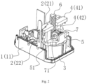
- the telescopic mechanism of the European plug of the power converter with the grounding pin in the embodiment further comprises a fixed rack 5 arranged on the shell 1 and extending into the plug bush 3, a movable rack 6 connected with the pin assembly 4, and a gear 7 arranged on the plug bush 3 and meshed with the fixed rack 5 and the movable rack 6 respectively. As shown in Figs.
- the plug bush 3 and the pin assembly 4 are in a non-push-out state.
- the push handle 2 drives the plug bush 3 to move downwards, and the gear 7 on the plug bush 3 moves downwards. Since the fixed rack 5 is fixed on the shell 1, the continuously moved gear 7 can roll along the fixed rack 5, for example, rotate in direction A (counterclockwise) in Fig. 2 .
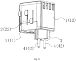
- the movable rack 6 is also driven to synchronously move downwards when the gear 7 continuously moves downwards along with the plug bush 3 and passes out of the shell 1, and then the movable rack 6 drives the pin assembly 4 to synchronously move downwards for a first stroke, so that the pin assembly 4 and the plug bush 3 synchronously pass out of the shell 1; meanwhile, when the gear 7 rotates due to the presence of the fixed rack 5, the gear 7 synchronously pushes the movable rack 6 meshed with the gear 7 downwards, the movable rack 6 drives the pin assembly 4 to synchronously move downwards for a second stroke, and the pin assembly 4 moves downwards for the second stroke relative to the plug bush 3, so that a lower end of the pin assembly 4 passes out of the plug bush 3, as shown in Figs. 6-8 .
- the pin assembly 4 can also acquire a second stroke which moves downwards relative to the plug bush 3, so that the lower end of the pin assembly 4 passes out of the plug bush 3, i.e. the pin assembly 4 can acquire two strokes.
- the stroke of the push handle 2 can be set to be shorter when the plug bush 3 and the pin assembly 4 are pushed out similarly, so that the space occupied by the movement of the push handle 2 is reduced, the inner space of a product is saved, and the size of the product is reduced conveniently, which facilitates the miniaturization of the whole product.
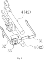
- the pin assembly 4 comprises two pins 42, two ground conductors 31, 32 are arranged on the plug bush 3, the two pins 42 and the two ground conductors 31, 32 are combined to form a hybrid grounding plug, and an additional contact sleeve 33 is provided on the hybrid grounding plug for a grounding pin of a French plug.
- the movable rack 6 is fixedly connected with the pin assembly 4.
- the pin assembly 4 further comprises a transverse connection block 41, and the two pins 42 are perpendicularly arranged at a lower end of the transverse connection block 41, wherein the movable rack 6 is fixedly connected with the transverse connection block 41. Therefore, the movable rack 6 is integrally connected with the transverse connection block 41, and when the movable rack 6 moves downwards, the pin assembly 4 is driven to move downwards synchronously.
- the gear 7 is fixed to the plug bush 3. Specifically, as shown in Fig. 2 , the gear 7 is fixed to the plug bush 3 by a screw 71. Of course, the gear 7 may be fixed to the plug bush 3 by other structures or other means. Therefore, the gear 7 is integrally connected with the plug bush 3, and when the plug bush 3 moves downwards, the gear 7 is driven to move downwards synchronously.
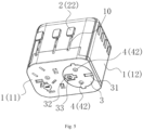
- the shell 1 comprises a base 11 and an upper cover 12 matched with the base 11, wherein an opening through which the plug bush 3 and the pin assembly 4 pass is formed in the base 11; and when the plug bush 3 and the pin assembly 4 are not pushed out, lower end surfaces of the plug bush 3 and the pin assembly 4 are flush with the opening, as shown in Fig. 5 . After the plug bush 3 and the pin assembly 4 are pushed out, lower parts of the plug bush 3 and the pin assembly 4 pass out of a lower end surface of the base 11 through the opening, as shown in Fig. 8 .
- the fixed rack 5 For the specific mounting of the fixed rack 5, it may be integrally formed on the base 11, or the fixed rack 5 may be longitudinally and fixedly mounted on the base 11 by a connector 51, so that the gear 7 can be meshed with the fixed rack 5, and the gear 7 can roll up and down along the fixed rack 5, as shown in Fig. 2 .
- the specific structure and configuration of the connector 51 can be set according to specific requirements, as shown in Figs. 2 and 6 .
- the telescopic mechanism provided by the embodiment of the invention is particularly suitable for a conversion plug, and the synchronous push-out function is realized for the plug bush 3 and the pin assembly 4 in the plug.
- the plug bush 3 and the pin assembly 4 can be pushed out only by pushing the push handle 2 downwards, and the plug bush 3 and the pin assembly 4 can be retracted by pushing the push handle 2 upwards.
- the plug bush 3 and the pin assembly 4 can be pushed out only by pushing the push handle 2 downwards, and the plug bush 3 and the pin assembly 4 can be retracted by pushing the push handle 2 upwards.
- the conventional conversion plug in the art.
- the telescopic mechanism provided by the embodiment is particularly suitable for use in European conversion plugs, such as German or French conversion plugs, particularly for use in high power appliances below 16 A.
- a locking structure 9 is arranged between the push handle 2 and the movable rack 6 and comprises at least one locking protrusion 91 arranged on the push handle 2 and at least one locking slot 92 formed on the movable rack 6 and used for clamping the locking protrusion 91.
- the locking protrusions 91 of the locking structure 9 are clamped into the locking slot 92, so that the movable rack 6 and the pin assembly 4 are integrally locked, and the movable rack 6 and the pin assembly 4 cannot be automatically retracted, which is convenient for the product use; and the two pins 42 of the pin assembly 4 and the plug bush 3 can be retracted into the shell 1 only if the locking protrusion 91 leaves the locking slot 92 to release the locking by pushing the push handle 2.
- the locking protrusion 91 of the locking structure 9 is clamped into the locking slot 92, so that the movable rack 6 and the pin assembly 4 are integrally locked, and the two pins 42 and the plug bush 3 cannot extend out automatically; and the two pins 42 and the plug bush 3 can be pushed out of the shell 1 only if the locking protrusion 91 leaves the locking slot 92 to release the locking by pushing the push handle 2.
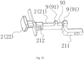
- the number of the locking protrusions 91 in the embodiment is two, and an avoiding slot 93 is formed between the two locking protrusions 91; accordingly, the number of the locking slot 92 is also two; and a longitudinal slide slot 94 extending longitudinally is formed in the movable rack 6, and the two locking slots 92 are located at both sides of the longitudinal slide slot, as shown in Figs. 11 and 12 .
- a locked state the two locking protrusions 91 are clamped into the two locking slots 92 one by one; and in a contact locked state, one locking protrusion 91 is located in the longitudinal slide slot 94, and the other locking protrusion 91 is also moved to the side of the movable rack 6.
- the push handle 2 is movably connected with the plug bush 3 by a positioning seat 30, and a positioning slide hole 301 and a spring mounting slot 302 are respectively formed in the positioning seat 30; a positioning strip 211 which is slidably arranged in the positioning slide hole 301 and a push block 212 which is movable in the spring mounting slot 302 are formed in the push handle 2; and a spring 303 is arranged in the spring mounting slot 302, and the spring 303 is directly pushed by the push block 212.
- the push handle 2 slides on the positioning seat 30 to the locking protrusion 91 of the locking structure 9 for being clamped into the locking slot 92, so that the movable rack 6 and the pin assembly 4 are integrally locked.
- the push handle 2 is pushed into the shell 1, so that the locking protrusion 91 leaves the locking slot 92 to release the locking.
- the two pins 42 of the pin assembly and the plug bush 3 can be pushed out and retracted by pushing the push handle 2 up and down 4 while the spring 303 is compressed.
- the push handle 2 mainly consists of a linkage block 21 arranged in the shell 1 and a push part 22 connected to an end of the linkage block 21 and passing out of the shell 1, wherein the linkage block 21 is movably connected with the plug bush 3 by the positioning seat 30; and the locking protrusion 91, the positioning strip 211 and the push block 212 are all arranged on the linkage block 21. Therefore, when the linkage block 21 of the push handle 2 moves downwards, the plug bush 3 is driven to move downwards synchronously. Meanwhile, as shown in Fig. 5 , a strip-shaped hole 10 for the push part 22 to move up and down is formed in the shell 1, and the strip-shaped hole 10 provides a vertical path for the push part 22 to move up and down.
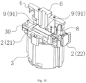
- At least one guide rod 8 is arranged in the shell 1, and the linkage block 21 and the positioning seat 30 are sleeved on the guide rod 8, as shown in Figs. 3 and 10 .
- the linkage block 21 can vertically move up and down along a plurality of guide rods 8, without the phenomena of displacement, bending and the like.
Landscapes
- Details Of Connecting Devices For Male And Female Coupling (AREA)
- Transmission Devices (AREA)
- Connector Housings Or Holding Contact Members (AREA)
- Input Circuits Of Receivers And Coupling Of Receivers And Audio Equipment (AREA)
Claims (12)
- Mécanisme télescopique pour une fiche européenne d'un convertisseur de puissance à broche de mise à la terre, comprenant un boîtier (1), une poignée poussoir (2) disposée sur le boîtier (1), une bague de fiche (3) disposée dans le boîtier (1) et reliée à la poignée poussoir (2), et un l'ensemble broche (4) disposé dans le boîtier (1), caractérisé en ce qu'il comprend en outreune crémaillère fixe (5) disposée sur le boîtier (1) et s'étend à l'intérieur de la bague de fiche (3),une crémaillère mobile (6) reliée à l'ensemble broche (4) etun engrenage (7) fixé sur la bague de fiche (3) ; dans lequella crémaillère mobile (6) et la crémaillère fixe (5) sont pourvues chacun des dents ; l'engrenage (7) s'engrène avec la crémaillère fixe (5) et avec la crémaillère mobile (6) à travers les dents respectivement ; la poignée poussoir (2) entraîne la bague de fiche (3) et l'engrenage (7) fixé sur la bague de fiche (3) à se déplacer ; l'engrenage (7) entraîne la crémaillère mobile (6) à se déplacer ; et la crémaillère mobile (6) entraîne l'ensemble broche (4) à se déplacer.
- Mécanisme télescopique pour une fiche européenne d'un convertisseur de puissance à broche de mise à la terre selon la revendication 1, caractérisé en ce que l'ensemble broche (4) comprend deux broches (42), deux conducteurs de terre (31, 32) sont disposés sur la bague de fiche (3), les deux broches (42) et les deux conducteurs de terre (31, 32) sont combinés pour former une fiche de mise à la terre hybride, et un manchon de contact supplémentaire (33) est prévu sur la fiche de mise à la terre hybride pour une broche de mise à la terre d'une fiche française.
- Mécanisme télescopique pour une fiche européenne d'un convertisseur de puissance à broche de mise à la terre selon la revendication 2, caractérisé en ce que la crémaillère mobile (6) est reliée de manière fixe à l'ensemble broche (4).
- Mécanisme télescopique pour une fiche européenne d'un convertisseur de puissance à broche de mise à la terre selon la revendication 3, caractérisé en ce que l'ensemble broche (4) comprend en outre un bloc de liaison transversale (41), et les deux broches (42) sont disposées perpendiculairement à une extrémité inférieure du bloc de liaison transversale (41), dans lequel la crémaillère mobile (6) est reliée de manière fixe au bloc de liaison transversale (41).
- Mécanisme télescopique pour une fiche européenne d'un convertisseur de puissance à broche de mise à la terre selon la revendication 1, caractérisé en ce que l'engrenage (7) est fixé à la bague de fiche (3) par une vis (71).
- Mécanisme télescopique pour une fiche européenne d'un convertisseur de puissance à broche de mise à la terre selon la revendication 1, caractérisé en ce que le boîtier (1) comprend une base (11) et un couvercle supérieur (12) correspondant à la base (11), dans lequel une ouverture à traverse laquelle passent la bague de fiche (3) et l'ensemble broche (4) est formée dans la base (H).
- Mécanisme télescopique pour une fiche européenne d'un convertisseur de puissance à broche de mise à la terre selon la revendication 6, caractérisé en ce que la crémaillère fixe (5) est formé de manière intégrale sur la base (11), ou fixée longitudinalement sur la base (11) par un connecteur (51).
- Mécanisme télescopique pour une fiche européenne d'un convertisseur de puissance à broche de mise à la terre selon la revendication 6, caractérisé en ce que la crémaillère fixe (5) est fixée longitudinalement au couvercle supérieur (12).
- Mécanisme télescopique pour une fiche européenne d'un convertisseur de puissance à broche de mise à la terre selon l'une quelconque des revendications 1 à 8, caractérisé en ce qu'une structure de verrouillage (9) est disposée entre la poignée poussoir (2) et la crémaillère mobile (6) et comprend au moins une saillie de verrouillage (91) disposée sur la poignée poussoir (2) et au moins une fente de verrouillage (92) formée sur la crémaillère mobile (6) et configurée pour serrer la saillie de verrouillage (91).
- Mécanisme télescopique pour une fiche européenne d'un convertisseur de puissance à broche de mise à la terre selon la revendication 9, caractérisé en ce que la poignée poussoir (2) est reliée de manière mobile à la bague de fiche (3) par ,un siège de positionnement (30), et un trou de glissière de positionnement (301) et une fente de montage de ressort (302) sont respectivement formés dans le siège de positionnement (30) ; et une bande de positionnement (211) qui est disposée de manière coulissante dans le trou glissant de positionnement (301) et un bloc poussoir (212) qui est mobile dans la fente de montage de ressort (302) sont formés dans la poignée poussoir (2), et un ressort (303) est disposé dans la fente de montage de ressort (302).
- Mécanisme télescopique pour une fiche européenne d'un convertisseur de puissance à broche de mise à la terre selon la revendication 10, caractérisé en ce que la poignée poussoir (2) est essentiellement constituée d'un bloc de liaison (21) disposé dans le boîtier (1) et d'une portion poussoir (22) reliée à une extrémité du bloc de liaison (21) et s'étendant hors du boîtier (1), dans lequel le bloc de liaison (21) est relié de manière mobile à la bague de fiche (3) par le siège de positionnement (30) ; la saillie de verrouillage (91), la bande de positionnement (211) et le bloc poussoir (212) sont tous disposés sur le bloc de liaison (21) ; de plus, un trou en forme de bande (10) permettant à la portion poussoir (22) de se déplace de haut en bas est formé dans le boîtier (1).
- Mécanisme télescopique pour une fiche européenne d'un convertisseur de puissance à broche de mise à la terre selon la revendication 11, caractérisé en ce qu'au moins une tige de guidage (8) est disposée dans le boîtier (1), et que le bloc de liaison (21) et le siège de positionnement (30) sont gainés sur la tige de guidage (8).
Applications Claiming Priority (2)
| Application Number | Priority Date | Filing Date | Title |
|---|---|---|---|
| CN202010285974.4A CN111478110A (zh) | 2020-04-13 | 2020-04-13 | 一种转换插头伸出机构 |
| CN202110372273.9A CN113161805B (zh) | 2020-04-13 | 2021-04-07 | 一种带有接地插脚的电源转换器欧式插头的伸缩机构 |
Publications (3)
| Publication Number | Publication Date |
|---|---|
| EP3896802A1 EP3896802A1 (fr) | 2021-10-20 |
| EP3896802B1 true EP3896802B1 (fr) | 2023-12-06 |
| EP3896802C0 EP3896802C0 (fr) | 2023-12-06 |
Family
ID=71752234
Family Applications (1)
| Application Number | Title | Priority Date | Filing Date |
|---|---|---|---|
| EP21167937.8A Active EP3896802B1 (fr) | 2020-04-13 | 2021-04-12 | Mécanisme télescopique de la fiche européenne d'un convertisseur de puissance comprenant une broche de mise à la terre |
Country Status (14)
| Country | Link |
|---|---|
| US (1) | US11489302B2 (fr) |
| EP (1) | EP3896802B1 (fr) |
| JP (1) | JP3241164U (fr) |
| KR (1) | KR200497471Y1 (fr) |
| CN (3) | CN111478110A (fr) |
| AU (1) | AU2021101880A4 (fr) |
| CA (1) | CA3114619C (fr) |
| ES (1) | ES2973139T3 (fr) |
| GB (1) | GB2592771B (fr) |
| HU (1) | HUE065653T2 (fr) |
| IL (1) | IL296871B2 (fr) |
| PL (1) | PL3896802T3 (fr) |
| SA (1) | SA522440902B1 (fr) |
| WO (1) | WO2021208311A1 (fr) |
Families Citing this family (15)
| Publication number | Priority date | Publication date | Assignee | Title |
|---|---|---|---|---|
| CN111478110A (zh) * | 2020-04-13 | 2020-07-31 | 东莞市佳旅电器有限公司 | 一种转换插头伸出机构 |
| CA200784S (en) * | 2020-07-24 | 2022-08-23 | Dongguan Best Travel Electronics Co Ltd | Power adapter |
| CN112864689B (zh) * | 2021-01-05 | 2023-06-23 | 深圳市绿联科技股份有限公司 | 一种可收纳的电力插头、插线板和电器 |
| CN114006235B (zh) * | 2021-11-15 | 2025-05-20 | 深圳市欧力科技有限公司 | 一种转换器 |
| CN115616304B (zh) * | 2022-09-22 | 2024-07-02 | 国网山东省电力公司淄博供电公司 | 一键式低压双电源智能核相装置 |
| USD1103920S1 (en) * | 2022-09-30 | 2025-12-02 | Feng Wang | Electrical plug |
| USD1082687S1 (en) * | 2022-09-30 | 2025-07-08 | Feng Wang | Electrical plug |
| USD1007432S1 (en) * | 2023-01-20 | 2023-12-12 | Feng Wang | Socket |
| CN116267278B (zh) * | 2023-04-25 | 2024-05-24 | 河北省农林科学院石家庄果树研究所 | 葡萄枝条等高修剪装置 |
| USD1052531S1 (en) * | 2023-06-08 | 2024-11-26 | Yanli Zhang | Electric socket |
| USD1018073S1 (en) * | 2023-11-21 | 2024-03-19 | Huashan Zhong | Voltage converter |
| TWM666194U (zh) * | 2023-12-13 | 2025-02-11 | 大陸商東莞市佳旅電器有限公司 | 一種插腳組件的防觸電檔板結構 |
| CN118156881B (zh) * | 2024-04-08 | 2025-02-14 | 深圳市欧力科技有限公司 | 一种旅行转换器 |
| CN118281625B (zh) * | 2024-04-08 | 2024-11-29 | 深圳市欧力科技有限公司 | 一种电源转换器欧式插头的伸缩结构 |
| CN118336422B (zh) * | 2024-05-17 | 2024-09-06 | 东莞市燊瑞电子科技有限公司 | 一种磁力式隐藏充电底座 |
Citations (10)
| Publication number | Priority date | Publication date | Assignee | Title |
|---|---|---|---|---|
| EP1387448A2 (fr) | 2002-08-01 | 2004-02-04 | Comarco Wireless Technologies, Inc. | Connecteur électrique pliable |
| CN2692880Y (zh) | 2004-01-18 | 2005-04-13 | 廖生兴 | 多功能插头变换器 |
| US7220139B1 (en) | 2006-07-04 | 2007-05-22 | Hsi-Fan Chang | Universal power adapter |
| WO2013038204A1 (fr) | 2011-09-16 | 2013-03-21 | Dg International Holdings Limited | Adaptateur |
| EP3252884A1 (fr) | 2016-06-01 | 2017-12-06 | Travel Blue Limited | Prise de voyage compacte |
| CN107611684A (zh) | 2017-09-19 | 2018-01-19 | 广州万浦电器有限公司 | 一种多用途可伸缩插头以及组合式转换插座 |
| WO2018064780A1 (fr) | 2016-10-07 | 2018-04-12 | Q2Power Ag | Fiche universelle |
| EP3316422A1 (fr) | 2016-11-01 | 2018-05-02 | Travel Blue Limited | Adaptateur électrique de voyage facile à utiliser |
| US20190288437A1 (en) | 2017-03-17 | 2019-09-19 | Cable Gear Holdings Llc | Electrical plug and adapter with retractable prongs |
| EP3671979A1 (fr) | 2018-12-21 | 2020-06-24 | WorldConnect AG | Adaptateur de voyage ainsi qu'ensemble comprenant un adaptateur de voyage |
Family Cites Families (14)
| Publication number | Priority date | Publication date | Assignee | Title |
|---|---|---|---|---|
| CN201160004Y (zh) * | 2008-01-22 | 2008-12-03 | 富士康(昆山)电脑接插件有限公司 | 移动存储装置 |
| JP2011524613A (ja) * | 2008-06-17 | 2011-09-01 | ラフナー,ウォルター | 多用途摺動プラグ |
| CN100568637C (zh) | 2008-11-21 | 2009-12-09 | 深圳市派高模业有限公司 | 一种插头插座适配器 |
| CN101872911B (zh) * | 2010-05-18 | 2012-11-07 | 智嘉通讯科技(东莞)有限公司 | 旋转选择推出式多国电源转接器 |
| CN104601744A (zh) * | 2013-10-31 | 2015-05-06 | 富泰华工业(深圳)有限公司 | 具有推出机构的移动终端 |
| SE537610C2 (sv) * | 2013-11-20 | 2015-07-28 | Eazyplug Ab | Elektrisk stickpropp |
| CN207474762U (zh) * | 2017-11-15 | 2018-06-08 | 广州万浦电器有限公司 | 多功能转换插头以及组合式转换插座 |
| CN207925793U (zh) * | 2018-03-20 | 2018-09-28 | 上海工程技术大学 | 一种改良型两脚插头 |
| CN109524817A (zh) * | 2018-11-20 | 2019-03-26 | 许汉平 | 一种可伸缩插头 |
| CN209608375U (zh) * | 2019-05-23 | 2019-11-08 | 深圳市盈辉电子有限公司 | 一种便于调节的手机适配器 |
| CN110098533A (zh) * | 2019-06-10 | 2019-08-06 | 贵州工程应用技术学院 | 一种防触电易单手拔出的插头 |
| CN110571600A (zh) * | 2019-09-28 | 2019-12-13 | 胡伟 | 智能型插头与插座组件 |
| CN110994309B (zh) * | 2020-01-02 | 2024-07-23 | 东莞永旅电器科技有限公司 | 一种多功能转接插头 |
| CN111478110A (zh) * | 2020-04-13 | 2020-07-31 | 东莞市佳旅电器有限公司 | 一种转换插头伸出机构 |
-
2020
- 2020-04-13 CN CN202010285974.4A patent/CN111478110A/zh active Pending
- 2020-08-19 WO PCT/CN2020/110062 patent/WO2021208311A1/fr not_active Ceased
- 2020-08-19 JP JP2022600031U patent/JP3241164U/ja active Active
- 2020-08-19 IL IL296871A patent/IL296871B2/en unknown
-
2021
- 2021-04-07 CN CN202120706153.3U patent/CN215008739U/zh active Active
- 2021-04-07 CN CN202110372273.9A patent/CN113161805B/zh active Active
- 2021-04-12 CA CA3114619A patent/CA3114619C/fr active Active
- 2021-04-12 EP EP21167937.8A patent/EP3896802B1/fr active Active
- 2021-04-12 PL PL21167937.8T patent/PL3896802T3/pl unknown
- 2021-04-12 HU HUE21167937A patent/HUE065653T2/hu unknown
- 2021-04-12 GB GB2105184.2A patent/GB2592771B/en active Active
- 2021-04-12 KR KR2020210001138U patent/KR200497471Y1/ko active Active
- 2021-04-12 US US17/228,610 patent/US11489302B2/en active Active
- 2021-04-12 ES ES21167937T patent/ES2973139T3/es active Active
- 2021-04-13 AU AU2021101880A patent/AU2021101880A4/en active Active
-
2022
- 2022-10-12 SA SA522440902A patent/SA522440902B1/ar unknown
Patent Citations (10)
| Publication number | Priority date | Publication date | Assignee | Title |
|---|---|---|---|---|
| EP1387448A2 (fr) | 2002-08-01 | 2004-02-04 | Comarco Wireless Technologies, Inc. | Connecteur électrique pliable |
| CN2692880Y (zh) | 2004-01-18 | 2005-04-13 | 廖生兴 | 多功能插头变换器 |
| US7220139B1 (en) | 2006-07-04 | 2007-05-22 | Hsi-Fan Chang | Universal power adapter |
| WO2013038204A1 (fr) | 2011-09-16 | 2013-03-21 | Dg International Holdings Limited | Adaptateur |
| EP3252884A1 (fr) | 2016-06-01 | 2017-12-06 | Travel Blue Limited | Prise de voyage compacte |
| WO2018064780A1 (fr) | 2016-10-07 | 2018-04-12 | Q2Power Ag | Fiche universelle |
| EP3316422A1 (fr) | 2016-11-01 | 2018-05-02 | Travel Blue Limited | Adaptateur électrique de voyage facile à utiliser |
| US20190288437A1 (en) | 2017-03-17 | 2019-09-19 | Cable Gear Holdings Llc | Electrical plug and adapter with retractable prongs |
| CN107611684A (zh) | 2017-09-19 | 2018-01-19 | 广州万浦电器有限公司 | 一种多用途可伸缩插头以及组合式转换插座 |
| EP3671979A1 (fr) | 2018-12-21 | 2020-06-24 | WorldConnect AG | Adaptateur de voyage ainsi qu'ensemble comprenant un adaptateur de voyage |
Non-Patent Citations (1)
| Title |
|---|
| ANONYMOUS: "Schuko ", WIKIPEDIA, 4 April 2020 (2020-04-04), pages 1 - 5, XP093208635, Retrieved from the Internet <URL:https://en.wikipedia.org/w/index.php?title=Schuko&oldid=949091240> [retrieved on 20240925] |
Also Published As
| Publication number | Publication date |
|---|---|
| HUE065653T2 (hu) | 2024-06-28 |
| PL3896802T3 (pl) | 2024-06-10 |
| CN215008739U (zh) | 2021-12-03 |
| EP3896802C0 (fr) | 2023-12-06 |
| JP3241164U (ja) | 2023-03-09 |
| GB202105184D0 (en) | 2021-05-26 |
| US11489302B2 (en) | 2022-11-01 |
| GB2592771B (en) | 2023-03-29 |
| ES2973139T3 (es) | 2024-06-18 |
| EP3896802A1 (fr) | 2021-10-20 |
| KR20210002348U (ko) | 2021-10-21 |
| CN113161805B (zh) | 2026-01-09 |
| IL296871A (en) | 2022-11-01 |
| GB2592771A (en) | 2021-09-08 |
| SA522440902B1 (ar) | 2024-01-24 |
| CA3114619A1 (fr) | 2021-10-13 |
| IL296871B1 (en) | 2025-01-01 |
| IL296871B2 (en) | 2025-05-01 |
| WO2021208311A1 (fr) | 2021-10-21 |
| KR200497471Y1 (ko) | 2023-11-17 |
| AU2021101880A4 (en) | 2021-06-03 |
| CA3114619C (fr) | 2023-06-06 |
| CN111478110A (zh) | 2020-07-31 |
| US20210320467A1 (en) | 2021-10-14 |
| CN113161805A (zh) | 2021-07-23 |
Similar Documents
| Publication | Publication Date | Title |
|---|---|---|
| EP3896802B1 (fr) | Mécanisme télescopique de la fiche européenne d'un convertisseur de puissance comprenant une broche de mise à la terre | |
| CN105206993B (zh) | 插头可伸缩收纳的转换器 | |
| CN105261908B (zh) | 带有伸缩式插头的插座转换器 | |
| CN105261907A (zh) | 一种可伸缩的地极插销转换器 | |
| CN204966838U (zh) | 插头可伸缩收纳的转换器 | |
| CN204966897U (zh) | 一种可伸缩的地极插销转换器 | |
| CN110011147A (zh) | 一种插脚可收纳的转换插头 | |
| HK40059882A (en) | Telescopic mechanism of european plug of power converter with grounding pin | |
| CN204966913U (zh) | 带有伸缩式插头的插座转换器 | |
| TWM632685U (zh) | 一種帶有接地插腳的電源轉換器歐式插頭的伸縮機構 | |
| AU2024205582B2 (en) | Conversion and conduction structure for power converter. | |
| CN212874982U (zh) | 一种用于多国电源转换器的防单插保护门组件 | |
| CN212392431U (zh) | 一种转换插头伸出机构 | |
| CN118156881B (zh) | 一种旅行转换器 | |
| CN223390917U (zh) | 一种多功能转换器的单插头伸出限位结构 | |
| CN223206596U (zh) | 一种插头布局紧凑的多功能转换器 | |
| CN223206504U (zh) | 一种多功能转换器的保护门结构 | |
| CN222735844U (zh) | 移动电源 | |
| US20250323466A1 (en) | Pin assembly structure with multiple pin specifications | |
| CN110854580A (zh) | 一种具有可靠持久复位功能的弹簧型插座 | |
| CN217607084U (zh) | 一种组合式保护门插座 | |
| CN224110630U (zh) | 一种电源转换器外壳 | |
| US20250309587A1 (en) | Socket Device | |
| US20250300390A1 (en) | Conversion Socket | |
| HK40118565A (en) | Conversion and conduction structure for power converter |
Legal Events
| Date | Code | Title | Description |
|---|---|---|---|
| PUAI | Public reference made under article 153(3) epc to a published international application that has entered the european phase |
Free format text: ORIGINAL CODE: 0009012 |
|
| STAA | Information on the status of an ep patent application or granted ep patent |
Free format text: STATUS: THE APPLICATION HAS BEEN PUBLISHED |
|
| AK | Designated contracting states |
Kind code of ref document: A1 Designated state(s): AL AT BE BG CH CY CZ DE DK EE ES FI FR GB GR HR HU IE IS IT LI LT LU LV MC MK MT NL NO PL PT RO RS SE SI SK SM TR |
|
| B565 | Issuance of search results under rule 164(2) epc |
Effective date: 20210909 |
|
| STAA | Information on the status of an ep patent application or granted ep patent |
Free format text: STATUS: REQUEST FOR EXAMINATION WAS MADE |
|
| 17P | Request for examination filed |
Effective date: 20220418 |
|
| RBV | Designated contracting states (corrected) |
Designated state(s): AL AT BE BG CH CY CZ DE DK EE ES FI FR GB GR HR HU IE IS IT LI LT LU LV MC MK MT NL NO PL PT RO RS SE SI SK SM TR |
|
| GRAP | Despatch of communication of intention to grant a patent |
Free format text: ORIGINAL CODE: EPIDOSNIGR1 |
|
| STAA | Information on the status of an ep patent application or granted ep patent |
Free format text: STATUS: GRANT OF PATENT IS INTENDED |
|
| INTG | Intention to grant announced |
Effective date: 20230719 |
|
| GRAS | Grant fee paid |
Free format text: ORIGINAL CODE: EPIDOSNIGR3 |
|
| GRAA | (expected) grant |
Free format text: ORIGINAL CODE: 0009210 |
|
| STAA | Information on the status of an ep patent application or granted ep patent |
Free format text: STATUS: THE PATENT HAS BEEN GRANTED |
|
| AK | Designated contracting states |
Kind code of ref document: B1 Designated state(s): AL AT BE BG CH CY CZ DE DK EE ES FI FR GB GR HR HU IE IS IT LI LT LU LV MC MK MT NL NO PL PT RO RS SE SI SK SM TR |
|
| REG | Reference to a national code |
Ref country code: GB Ref legal event code: FG4D |
|
| REG | Reference to a national code |
Ref country code: CH Ref legal event code: EP |
|
| REG | Reference to a national code |
Ref country code: DE Ref legal event code: R096 Ref document number: 602021007394 Country of ref document: DE |
|
| REG | Reference to a national code |
Ref country code: IE Ref legal event code: FG4D |
|
| U01 | Request for unitary effect filed |
Effective date: 20231227 |
|
| U07 | Unitary effect registered |
Designated state(s): AT BE BG DE DK EE FI FR IT LT LU LV MT NL PT SE SI Effective date: 20240110 |
|
| REG | Reference to a national code |
Ref country code: GR Ref legal event code: EP Ref document number: 20240400408 Country of ref document: GR Effective date: 20240312 |
|
| U20 | Renewal fee for the european patent with unitary effect paid |
Year of fee payment: 4 Effective date: 20240419 |
|
| PG25 | Lapsed in a contracting state [announced via postgrant information from national office to epo] |
Ref country code: RS Free format text: LAPSE BECAUSE OF FAILURE TO SUBMIT A TRANSLATION OF THE DESCRIPTION OR TO PAY THE FEE WITHIN THE PRESCRIBED TIME-LIMIT Effective date: 20231206 Ref country code: NO Free format text: LAPSE BECAUSE OF FAILURE TO SUBMIT A TRANSLATION OF THE DESCRIPTION OR TO PAY THE FEE WITHIN THE PRESCRIBED TIME-LIMIT Effective date: 20240306 Ref country code: HR Free format text: LAPSE BECAUSE OF FAILURE TO SUBMIT A TRANSLATION OF THE DESCRIPTION OR TO PAY THE FEE WITHIN THE PRESCRIBED TIME-LIMIT Effective date: 20231206 |
|
| REG | Reference to a national code |
Ref country code: ES Ref legal event code: FG2A Ref document number: 2973139 Country of ref document: ES Kind code of ref document: T3 Effective date: 20240618 |
|
| REG | Reference to a national code |
Ref country code: HU Ref legal event code: AG4A Ref document number: E065653 Country of ref document: HU |
|
| PG25 | Lapsed in a contracting state [announced via postgrant information from national office to epo] |
Ref country code: IS Free format text: LAPSE BECAUSE OF FAILURE TO SUBMIT A TRANSLATION OF THE DESCRIPTION OR TO PAY THE FEE WITHIN THE PRESCRIBED TIME-LIMIT Effective date: 20240406 |
|
| PG25 | Lapsed in a contracting state [announced via postgrant information from national office to epo] |
Ref country code: CZ Free format text: LAPSE BECAUSE OF FAILURE TO SUBMIT A TRANSLATION OF THE DESCRIPTION OR TO PAY THE FEE WITHIN THE PRESCRIBED TIME-LIMIT Effective date: 20231206 |
|
| PG25 | Lapsed in a contracting state [announced via postgrant information from national office to epo] |
Ref country code: SK Free format text: LAPSE BECAUSE OF FAILURE TO SUBMIT A TRANSLATION OF THE DESCRIPTION OR TO PAY THE FEE WITHIN THE PRESCRIBED TIME-LIMIT Effective date: 20231206 |
|
| PG25 | Lapsed in a contracting state [announced via postgrant information from national office to epo] |
Ref country code: SM Free format text: LAPSE BECAUSE OF FAILURE TO SUBMIT A TRANSLATION OF THE DESCRIPTION OR TO PAY THE FEE WITHIN THE PRESCRIBED TIME-LIMIT Effective date: 20231206 Ref country code: SK Free format text: LAPSE BECAUSE OF FAILURE TO SUBMIT A TRANSLATION OF THE DESCRIPTION OR TO PAY THE FEE WITHIN THE PRESCRIBED TIME-LIMIT Effective date: 20231206 Ref country code: RO Free format text: LAPSE BECAUSE OF FAILURE TO SUBMIT A TRANSLATION OF THE DESCRIPTION OR TO PAY THE FEE WITHIN THE PRESCRIBED TIME-LIMIT Effective date: 20231206 Ref country code: IS Free format text: LAPSE BECAUSE OF FAILURE TO SUBMIT A TRANSLATION OF THE DESCRIPTION OR TO PAY THE FEE WITHIN THE PRESCRIBED TIME-LIMIT Effective date: 20240406 Ref country code: CZ Free format text: LAPSE BECAUSE OF FAILURE TO SUBMIT A TRANSLATION OF THE DESCRIPTION OR TO PAY THE FEE WITHIN THE PRESCRIBED TIME-LIMIT Effective date: 20231206 |
|
| REG | Reference to a national code |
Ref country code: DE Ref legal event code: R026 Ref document number: 602021007394 Country of ref document: DE |
|
| PLBI | Opposition filed |
Free format text: ORIGINAL CODE: 0009260 |
|
| PLAB | Opposition data, opponent's data or that of the opponent's representative modified |
Free format text: ORIGINAL CODE: 0009299OPPO |
|
| 26 | Opposition filed |
Opponent name: TRAVEL BLUE LIMITED Effective date: 20240814 |
|
| PLAX | Notice of opposition and request to file observation + time limit sent |
Free format text: ORIGINAL CODE: EPIDOSNOBS2 |
|
| R26 | Opposition filed (corrected) |
Opponent name: TRAVEL BLUE LIMITED Effective date: 20240814 |
|
| PG25 | Lapsed in a contracting state [announced via postgrant information from national office to epo] |
Ref country code: MC Free format text: LAPSE BECAUSE OF FAILURE TO SUBMIT A TRANSLATION OF THE DESCRIPTION OR TO PAY THE FEE WITHIN THE PRESCRIBED TIME-LIMIT Effective date: 20231206 |
|
| PG25 | Lapsed in a contracting state [announced via postgrant information from national office to epo] |
Ref country code: MC Free format text: LAPSE BECAUSE OF FAILURE TO SUBMIT A TRANSLATION OF THE DESCRIPTION OR TO PAY THE FEE WITHIN THE PRESCRIBED TIME-LIMIT Effective date: 20231206 |
|
| PLBB | Reply of patent proprietor to notice(s) of opposition received |
Free format text: ORIGINAL CODE: EPIDOSNOBS3 |
|
| U20 | Renewal fee for the european patent with unitary effect paid |
Year of fee payment: 5 Effective date: 20250418 |
|
| PGFP | Annual fee paid to national office [announced via postgrant information from national office to epo] |
Ref country code: PL Payment date: 20250422 Year of fee payment: 5 |
|
| PGFP | Annual fee paid to national office [announced via postgrant information from national office to epo] |
Ref country code: GB Payment date: 20250423 Year of fee payment: 5 Ref country code: ES Payment date: 20250519 Year of fee payment: 5 |
|
| PGFP | Annual fee paid to national office [announced via postgrant information from national office to epo] |
Ref country code: HU Payment date: 20250512 Year of fee payment: 5 |
|
| PGFP | Annual fee paid to national office [announced via postgrant information from national office to epo] |
Ref country code: GR Payment date: 20250416 Year of fee payment: 5 |
|
| PGFP | Annual fee paid to national office [announced via postgrant information from national office to epo] |
Ref country code: CH Payment date: 20250501 Year of fee payment: 5 |
|
| PGFP | Annual fee paid to national office [announced via postgrant information from national office to epo] |
Ref country code: TR Payment date: 20250411 Year of fee payment: 5 |
|
| PGFP | Annual fee paid to national office [announced via postgrant information from national office to epo] |
Ref country code: IE Payment date: 20250428 Year of fee payment: 5 |
|
| PG25 | Lapsed in a contracting state [announced via postgrant information from national office to epo] |
Ref country code: CY Free format text: LAPSE BECAUSE OF FAILURE TO SUBMIT A TRANSLATION OF THE DESCRIPTION OR TO PAY THE FEE WITHIN THE PRESCRIBED TIME-LIMIT; INVALID AB INITIO Effective date: 20210412 |
|
| RDAF | Communication despatched that patent is revoked |
Free format text: ORIGINAL CODE: EPIDOSNREV1 |
|
| APAH | Appeal reference modified |
Free format text: ORIGINAL CODE: EPIDOSCREFNO |
|
| APBP | Date of receipt of notice of appeal recorded |
Free format text: ORIGINAL CODE: EPIDOSNNOA2O |
|
| APBQ | Date of receipt of statement of grounds of appeal recorded |
Free format text: ORIGINAL CODE: EPIDOSNNOA3O |