EP3896844B1 - Panneaux solaires empilés - Google Patents
Panneaux solaires empilés Download PDFInfo
- Publication number
- EP3896844B1 EP3896844B1 EP21164064.4A EP21164064A EP3896844B1 EP 3896844 B1 EP3896844 B1 EP 3896844B1 EP 21164064 A EP21164064 A EP 21164064A EP 3896844 B1 EP3896844 B1 EP 3896844B1
- Authority
- EP
- European Patent Office
- Prior art keywords
- solar
- frame
- substrate
- solar panels
- panels
- Prior art date
- Legal status (The legal status is an assumption and is not a legal conclusion. Google has not performed a legal analysis and makes no representation as to the accuracy of the status listed.)
- Active
Links
Images








Classifications
-
- H—ELECTRICITY
- H02—GENERATION; CONVERSION OR DISTRIBUTION OF ELECTRIC POWER
- H02S—GENERATION OF ELECTRIC POWER BY CONVERSION OF INFRARED RADIATION, VISIBLE LIGHT OR ULTRAVIOLET LIGHT, e.g. USING PHOTOVOLTAIC [PV] MODULES
- H02S30/00—Structural details of PV modules other than those related to light conversion
- H02S30/20—Collapsible or foldable PV modules
-
- B—PERFORMING OPERATIONS; TRANSPORTING
- B64—AIRCRAFT; AVIATION; COSMONAUTICS
- B64G—COSMONAUTICS; VEHICLES OR EQUIPMENT THEREFOR
- B64G1/00—Cosmonautic vehicles
- B64G1/22—Parts of, or equipment specially adapted for fitting in or to, cosmonautic vehicles
- B64G1/222—Parts of, or equipment specially adapted for fitting in or to, cosmonautic vehicles for deploying structures between a stowed and deployed state
- B64G1/2221—Parts of, or equipment specially adapted for fitting in or to, cosmonautic vehicles for deploying structures between a stowed and deployed state characterised by the manner of deployment
- B64G1/2222—Folding
-
- B—PERFORMING OPERATIONS; TRANSPORTING
- B64—AIRCRAFT; AVIATION; COSMONAUTICS
- B64G—COSMONAUTICS; VEHICLES OR EQUIPMENT THEREFOR
- B64G1/00—Cosmonautic vehicles
- B64G1/22—Parts of, or equipment specially adapted for fitting in or to, cosmonautic vehicles
- B64G1/42—Arrangements or adaptations of power supply systems
- B64G1/44—Arrangements or adaptations of power supply systems using radiation, e.g. deployable solar arrays
- B64G1/443—Photovoltaic cell arrays
-
- H—ELECTRICITY
- H02—GENERATION; CONVERSION OR DISTRIBUTION OF ELECTRIC POWER
- H02S—GENERATION OF ELECTRIC POWER BY CONVERSION OF INFRARED RADIATION, VISIBLE LIGHT OR ULTRAVIOLET LIGHT, e.g. USING PHOTOVOLTAIC [PV] MODULES
- H02S30/00—Structural details of PV modules other than those related to light conversion
- H02S30/10—Frame structures
-
- H—ELECTRICITY
- H02—GENERATION; CONVERSION OR DISTRIBUTION OF ELECTRIC POWER
- H02S—GENERATION OF ELECTRIC POWER BY CONVERSION OF INFRARED RADIATION, VISIBLE LIGHT OR ULTRAVIOLET LIGHT, e.g. USING PHOTOVOLTAIC [PV] MODULES
- H02S40/00—Components or accessories in combination with PV modules, not provided for in groups H02S10/00 - H02S30/00
- H02S40/40—Thermal components
- H02S40/42—Cooling means
-
- H—ELECTRICITY
- H10—SEMICONDUCTOR DEVICES; ELECTRIC SOLID-STATE DEVICES NOT OTHERWISE PROVIDED FOR
- H10F—INORGANIC SEMICONDUCTOR DEVICES SENSITIVE TO INFRARED RADIATION, LIGHT, ELECTROMAGNETIC RADIATION OF SHORTER WAVELENGTH OR CORPUSCULAR RADIATION
- H10F77/00—Constructional details of devices covered by this subclass
- H10F77/93—Interconnections
- H10F77/933—Interconnections for devices having potential barriers
- H10F77/935—Interconnections for devices having potential barriers for photovoltaic devices or modules
- H10F77/939—Output lead wires or elements
-
- Y—GENERAL TAGGING OF NEW TECHNOLOGICAL DEVELOPMENTS; GENERAL TAGGING OF CROSS-SECTIONAL TECHNOLOGIES SPANNING OVER SEVERAL SECTIONS OF THE IPC; TECHNICAL SUBJECTS COVERED BY FORMER USPC CROSS-REFERENCE ART COLLECTIONS [XRACs] AND DIGESTS
- Y02—TECHNOLOGIES OR APPLICATIONS FOR MITIGATION OR ADAPTATION AGAINST CLIMATE CHANGE
- Y02E—REDUCTION OF GREENHOUSE GAS [GHG] EMISSIONS, RELATED TO ENERGY GENERATION, TRANSMISSION OR DISTRIBUTION
- Y02E10/00—Energy generation through renewable energy sources
- Y02E10/50—Photovoltaic [PV] energy
Definitions
- the disclosure is related generally to solar cell panels and more specifically to a stacked solar array.
- a spacecraft often uses solar arrays for electric power generation.
- a solar array generally is comprised of solar panels connected together, wherein each solar panel is populated with solar cells to generate the electric power.
- Solar cells and their assemblies need to radiate heat away from the Sun to cool. As solar cells are built up into a solar array, the solar cells need to maintain high thermal conductivity to a radiating surface.
- This substrate could be a plastic sheet such as polyimide, a thin fiber composite, or thin metal sheet.
- This substrate has lateral strength, but is thin, lightweight, and likely flexible.
- a solar array based on rigid solar panels.
- This panel has more strength to deliver the rigidity and frequency response needed for the program.
- the panel is often an aluminum (Al) honeycomb with carbon composite face sheets.
- Al aluminum
- this attachment requires a large area adhesive bond to ensure thermal contact to the rigid panel radiating surface.
- the large area adhesive bond is a large mass of material, which is undesirable for space applications.
- Document US 2011/210209 A1 states a deployable structure that may include a slit-tube longeron and a flat panel coupled with the slit-tube longeron.
- the slit-tube longeron may include a tubular member having a slit that runs along the longitudinal length of the slit-tube longeron.
- the deployable structure may be configured to couple with a satellite.
- the deployable structure may be configured to transform between a stowed state and a deployed state where the tubular member is substantially straight when the deployable structure is in the deployed state, and the tubular member is wrapped around the satellite when the deployable structure is in the stowed state.
- Document JP 2003 318433 A discloses solar cell panels mounted on hatch covers that are used for covering an outdoor treatment tank.
- the hatch covers can be moved into each other in a sliding direction.
- an apparatus comprising at least first and second solar panels, wherein each of the first and second solar panels is comprised of a substrate having one or more solar cells bonded thereto, and a frame for supporting the substrate and the solar cells; the frame has a cutout or opening in a center of the frame and, when deployed, the cutout or opening enables cooling of the solar cells through the substrate by exposing a back side of the substrate and the solar cells for transferring or radiating heat directly through the cutout or opening of the frame; and the frame of the first solar panel is configured to be nested inside the cutout or opening of the frame of the second solar panel when the first and second solar panels are stowed in a stacked configuration; wherein the substrate and the solar cells for the first and second solar panels are positioned on opposite sides of the frames for the first and second solar panels, wherein the substrate and the solar cells for the first and second solar panels positioned on opposite sides of the frames for the first and second solar panels face a same direction when deployed, and/or the substrate and the solar cells for the first
- a method comprising stowing at least first and second solar panels, wherein each of the first and second solar panels is comprised of a substrate having one or more solar cells bonded thereto, and a frame for supporting the substrate and the solar cells; the frame has a cutout or opening in a center of the frame and, when deployed, the cutout or opening enables cooling of the solar cells through the substrate by exposing a back side of the substrate and the solar cells for transferring or radiating heat directly through the cutout or opening of the frame; and the frame of the first solar panel is configured to be nested inside the cutout or opening of the frame of the second solar panel when the first and second solar panels are stowed in a stacked configuration; wherein the substrate and the solar cells for the first and second solar panels are positioned on opposite sides of the frames for the first and second solar panels, wherein the substrate and the solar cells for the first and second solar panels positioned on the opposite sides of the frames for the first and second solar panels face a same direction when deployed, and/or the
- a solar array includes at least one solar panel comprised of one or more solar cells bonded onto a substrate, which may be a flexible substrate, and the substrate and the solar cells are then attached to a support frame having a cutout or opening in a center of the frame under the solar cells.
- the substrate is thin to facilitate heat flow and thus it has a low stiffness that may bend and warp making it unsuitable for flight alone.
- the substrate is attached to the frame that provides the stiffness for the structure to be used as a solar panel.
- the "flex on frame” concept for solar arrays has a number of advantages.
- the "flex on frame” concept has both cost and cycle time advantages, as compared to solar arrays with solid solar panels.
- thermal connection to the frame is not required, but is permissible, simplifying attachment of the circuit to the panel (e.g., simple mechanical fasteners or clamps).
- the frame can, but need not, take part in thermal transport from the solar cells like a solid solar panel.
- the frame provides mechanical support for the substrate with the solar cells bonded thereon. This enables separation of thermal and mechanical roles as compared to solid solar panels, if desired.
- the "flex on frame” concept for solar arrays may result in a less rigid structure than solid solar panels, for equivalent thickness structures.
- stiffness There is a correlation between stiffness and the fundamental mode or frequency of a solar panel, which is modified when a solar panel is solid as opposed to when it is a only a frame having a cutout or opening.
- Solid solar panels have high stiffness to have a higher fundamental mode or frequency, while the "flex on frame” concept has a lower fundamental mode or frequency than a solid solar panel of the same thickness.
- the vibrational frequency of the solar panels is an important metric. A more rigid structure having a higher fundamental mode or frequency results in a more stable spacecraft.
- This disclosure provides the "flex on frame” concept in a stacked configuration comprising at least two frames, each having a thickness, wherein a first frame is configured to nest with a second frame.
- a cutout or opening in a center of the frame allows multiple frames to be stacked inside of each other. This allows the frames to be thicker than a solid solar panel and therefore increases the rigidity in the stacked configuration during launch and transport, while reducing weight and enabling efficient thermal dissipation when deployed and operating.
- FIG. 1 is a schematic of a spacecraft 10 with one or more solar arrays 11 comprised of one or more solar panels 12.
- the spacecraft 10 comprises a satellite, and there are two (2) solar arrays 11, and four (4) solar panels 12, wherein each of the solar arrays 11 is comprised of two of the solar panels 12, and the solar arrays 11 and solar panels 12 extend on both sides of the spacecraft 10.
- the solar arrays 11 are attached to the spacecraft 10 by means of triangular trusses 13 or other mechanisms, and each of the solar panels 12 is attached to an adjacent solar panel 12 by means of hinges 14 or other mechanisms, wherein the triangular trusses 13 and hinges 14 allow the solar arrays 11 and solar panels 12 to be folded and stacked for storage during launch, and then extended and deployed during operation.
- FIGS. 2A, 2B and 2C are top-view, top-view and cross-sectional side-view schematics, respectively, illustrating the components and assembly of one of the solar panels 12, including a solar power module (SPM) 15 and a frame 16.
- SPM solar power module
- FIG. 2A shows the SPM 15, which is comprised of an array of solar cells 17 bonded to a substrate 18.
- the substrate 18 is a flexible substrate, namely a flex circuit comprised of a laminate of one or more Kapton TM insulating layers and one or more metal layers providing electrical interconnects.
- FIG. 2B shows the frame 16 for supporting the solar cells 17 and substrate 18, wherein the frame 16 is a rectangular structure formed, for example, of joined pieces defining a perimeter around a cut-out or opening in a center of the frame 16 under the solar cells 17.
- FIG. 2C shows the SPM 15 mounted on and attached to the frame 16, wherein the substrate 18 is attached to the frame 16 at a perimeter of the frame 16 along one or more edges of the substrate 18. Once mounted and attached, the SPM 15 and frame 16 comprise a solar panel 12.
- a conventional rigid solar panel is a solid shape, often rectangular, but can be any shape.
- the solar panel 12 is largely hollow due to the configuration of the frame 16.
- the substrate 18 is a thermal structure for radiating heat from the solar cells 17 into outer space
- the frame 16 is a mechanical structure for supporting the solar cells 17 and the substrate 18.
- the cutout or opening at the center of the frame 16 enables cooling of the solar cells 17 through the substrate 18 by exposing a back side of the substrate 18 for radiating heat directly through the cutout or opening of the frame 16. The goal is for the radiated heat flow of the solar cells 17 and the substrate 18 to outer space to be minimally shadowed by the mechanical structure of the frame 16.
- reinforcing materials and/or supporting members (not shown) inside the frame 16 to increase stiffness, wherein the reinforcing materials could be mesh, honeycomb material, or the like, and the supporting members could be various bars, channels, or the like. This is described in more detail below in conjunction with FIGS. 6A and 6B .
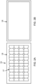
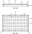
- FIGS. 3A and 3B are a cross-sectional side-view schematic and a top-view schematic, respectively, of the SPM 15, frame 16, solar cells 17 and substrate 18, wherein the substrate 18 is attached to the frame 16 using one or more fasteners 19 and reinforced areas 20.
- fasteners 19 can be used, including pins, posts, rivets or other structures, and the fasteners 19 may be comprised of metal, polymer, or other types of materials. Adhesives of various types could be used with the fasteners 19, or as an alternative to the fasteners 19, with continuous or spot application.
- the fasteners 19 may attach to a single surface of the frame 16 or extend through the frame 16. It may be desirable that the fasteners 19 are reversible to allow disassembly for repairs, and reversing the fasteners 19 could involve destroying them, such as in cutting or drilling the fasteners 19, which should not be a major concern due to their low cost.
- the fasteners 19 may be placed in reinforced areas 20 of the substrate 18 near the edges of the substrate 18, or in other areas of the substrate 18, to prevent tearing of the substrate 18.
- the reinforced areas 20 may be comprised of additional Kapton TM insulating layers, carbon fiber, Kevlar TM , and/or metal layers, or some other combination of layers, or some other material. It would be rather straightforward to pattern a copper (Cu) trace layer as a reinforcement.
- the frame 16 material may also be reinforced in proximity to the fasteners 19.
- the fasteners 19 are positioned on each of the four (4) sides of the frame 16, around the perimeter of the frame 16, and near the edges of the substrate 18. In other examples, it may only be necessary to attach the SPM 15 to two (2) opposing sides of the frame 16. On the other hand, attaching the SPM 15 to all four (4) sides of the frame 16 does offer assurances regarding the security of the attachment of the SPM 15 to the frame 16.
- FIGS. 4A and 4B are a cross-sectional side-view schematic and a top-view schematic, respectively, of the SPM 15, frame 16, solar cells 17, substrate 18, fasteners 19 and reinforced areas 20, wherein the substrate 18 is attached to the frame 16 using one or more bars 21 located along one or more sides of the frame 16, for example, in the reinforced areas 20 near the edges of the substrate 18 and between at least some of the fasteners 19 and the substrate 18.
- These bars 21 serve to spread the force applied by the fasteners 19 and thus minimize the risk of tearing the substrate 18.
- These bars 21 could be rectangular or another shape, preferably matching the geometry of the frame 16.
- the bars 21 could also be comprised of a series of one or more shorter segments.
- FIG. 3B illustrates reinforcement at a single attachment position, while FIG. 4B illustrates reinforcement that spans multiple attachment positions.
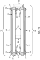
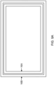
- FIGS. 5A , 5B , 5C and 5D are top-view schematics and FIG. 5E is a cross-sectional side-view schematic providing greater detail on electrical connections to the solar cells 17. It is preferred that wiring for the electrical connections to the solar cells 17 be on a back side of the substrate 18, so that as much area as possible on the front side of the solar cells 17 is used to collect the Sun's energy.
- FIG. 5A is a top-view schematic of the SPM 15, solar cells 17 and substrate 18, before being mounted on and attached to the frame 16, wherein the substrate 18 has one or more tabs 22 extending from one or more sides of the substrate 18.
- Each of the tabs 22 may be comprised of the same materials as the substrate 18, and may be contiguous portions of the substrate 18.
- Each of the tabs 22 may include one or more electrical conductors 23, patterned from one or more metal layers deposited on a surface of the tabs 22 and/or buried within the layers of the tabs 22, for making electrical connections to at least one of the solar cells 17.
- FIG. 5B is a top-view schematic of the SPM 15, frame 16, solar cells 17, substrate 18, fasteners 19, reinforced areas 20, and bars 21, wherein the substrate 18 is attached to the frame 16 with fasteners 19 at the reinforced areas 20 and bars 21, and the tabs 22 and electrical conductors 23 extend beyond the frame 16.
- FIG. 5C is a top-view schematic of the SPM 15, frame 16, solar cells 17, substrate 18, fasteners 19, reinforced areas 20, and bars 21, wherein the tabs 22 and electrical conductors 23 are folded around and under the frame 16.
- FIG. 5D is a bottom-view schematic of the frame 16, substrate 18, fasteners 19, and bars 21, wherein the tabs 22 and electrical conductors 23 are folded around and under the frame 16, and the tabs 22 are attached to the back side of the substrate 18, for example, with adhesive, fasteners, bars, or the like.
- the tabs 22 could also be attached to one or more sides of the frame 16, including the bottom side, front side and perimeter sides of the frame 16.
- the tabs 22 extend around the outside of the frame 16, and then pass under and are secured by the bars 21. Another option could be to pass the tabs 22 through a slot or channel in the frame 16.
- the substrate 18 could be structured to end at the opening of the frame 16, which would allow the tabs 22 to fold down inside the frame 16, instead of outside the edge of the frame 16.
- the tabs 22 could also be attached to one or more sides of the frame 16 and simply extend back away from the Sun.
- the electrical conductors 23 may be electrically connected to conductors or traces (not shown) deposited on the back side of the substrate 18 and/or buried within the substrate 18, through the use of exposed conductors or traces, vias and the like.
- FIG. 5E is a cross-sectional side-view schematic of the SPM 15, frame 16, solar cells 17, substrate 18, fasteners 19, bars 21 and tabs 22, wherein the tabs 22 are wrapped around the frame 16 to the back side of the substrate 18.
- the substrate 18 is visible on the top side of the frame 16 and bends around the outside of the frame 16.
- the tabs 22 are positioned to have minimal shadowing of the radiation from the back side of the substrate 18.
- the tabs 22 could be positioned behind the structure of the frame 16 to minimize shadowing.
- the ends of the tabs 22 are available to make connections to other electrical conductors, such as a wiring harness (not shown), to carry power to adjacent frames 16, panels 12, arrays 11, other structures, and the spacecraft 10 itself.
- a wiring harness (not shown)
- the wiring harness may be positioned along the back of the substrate 18, the back of the frame 16, or the side of the frame 16.
- the wiring harness may extend partially or completely inside the frame 16 when the frame 16 is comprised of hollow members.
- the electrical conductors in the wiring harness may form part of the frame 16 when the frame 16 is constructed as a composite or through additive manufacturing.
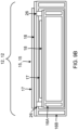
- FIG. 6A is a top-view schematic and FIG. 6B is a cross-sectional side-view schematic illustrating reinforcing materials 24 that may be used to fill the center of the frame 16, wherein FIG. 6A shows only the frame 16 and the reinforcing materials 24, and FIG. 6B shows the SPM 15 mounted on and attached to the frame 16, with the substrate 18 attached to both the frame 16 and the reinforcing materials 24, the solar cells 17 bonded to the substrate 18 above the reinforcing materials 24.
- these reinforcing materials 24 may be designed to allow radiation at normal incidence to reach the solar cells 17, and to block radiation at non-normal incidence from reaching the solar cells 17.
- space radiation e.g., electrons, protons, gamma rays
- the use of a honeycomb structure as the reinforcing materials 24 in the frame 16 can be used to block the space radiation at non-normal incidence, and thus shield the solar cells 17 from damage, while allowing radiative cooling 25 to occur at normal incidence.
- the solar panel 12 It is important for the solar panel 12 to pass acoustic and vibration testing. Attachment of the substrate 18 to the reinforcing materials 24 below the substrate 18 can limit vibrations and improve survivability. Acoustic and vibration environment occurs during the launch phase while the solar panels 12 are folded and stowed against the side of the spacecraft 10. In this condition, the solar cells 17 from one panel 12 may be facing the reinforcing materials 24 from a second panel 12. Their mechanical engagement should be designed to withstand the acoustic and vibration requirements. Employing shock absorbing or soft materials such as foam between the solar cells 17 or substrate 18 and the reinforcing materials 24 of the next panel 12 would be advantageous.
- FIGS. 7A and 7B are cross-sectional side-view schematics of the solar panels 12, wherein FIG. 7A shows a pair of solar panels 12 that are connected by a hinge 14 and stacked together, and FIG. 7B shows the pair of solar panels 12 extended into position while connected to the hinge 14. Also shown are the SPM 15, solar cells 17, substrate 18, frame 16, fasteners 19, bars 21, and tabs 22.
- the thickness of the stack formed by the pair of solar panels 12 comprises the thickness of each of the solar panels 12 panels and the spacing between them.
- One or more snubbers 24 may be positioned between the stacked solar panels 12, wherein the snubbers 26 are soft, shock absorbing materials such as foam that maintain pressure and contact between the solar panels 12 to minimize bow and vibration of the solar panels 12.
- FIGS. 8A , 8B and 8C are top-view, cross-sectional side-view, and side-view schematics, respectively, illustrating another configuration for the solar panels 12. While the frames 16 in FIGS. 7A and 7B are the same size, in this example there are different sizes for the frames 16 that provide for a different stowed configuration. Specifically, a smaller one or more of the frames 16A can be stacked inside a larger one or more of the frames 16B, as shown in FIG. 8A , wherein each of the frames 16A, 16B have slightly different widths.
- FIG. 8B shows a cross-sectional side-view with the solar panels 12 stowed together in a stacked configuration, and FIG.
- FIG. 8C shows a side-view with the solar panels 12 deployed.
- the SPM 15, solar cells 17 and substrate 18 are positioned on the same side of the smaller frame 16A as compared to the SPM 15, solar cells 17 and substrate 18 on the larger frame 16B.
- the hinge 14 connecting the solar panels 12 although the mechanism of the hinge 14 to accomplish the stacking and deployment of the solar panels 12 is not detailed here.
- the retracted solar array 11 is given a specific volume to occupy in the spacecraft 10 design.
- the conventional folding in FIG. 7A apportions less than half the height of the space to each solar panel 12.
- the new design shown in FIG. 8B shows how both panels 12 can be more than half the height of the space.
- the new design allows the panels 12 to have a greater height within the allowed space. This increased height increases its stiffness resulting in a more stable spacecraft 10.
- FIGS. 9A , 9B and 9C are top-view, cross-sectional side-view, and side-view schematics, respectively, illustrating yet another configuration for the solar panels 12.
- the SPM 15, solar cells 17 and substrate 18 are positioned on an opposite side of the smaller frame 16A as compared to the SPM 15, solar cells 17 and substrate 18 on the larger frame 16B.
- FIG. 9A is a top-view showing a smaller one or more of the frames 16A stacked inside a larger one or more of the frames 16B, wherein each of the frames 16A, 13B have slightly different widths.
- FIG. 9B is a cross-sectional side-view with the solar panels 12 stowed together in a stacked configuration
- FIG. 9C is a side-view with the solar panels 12 deployed.
- the substrate 18 is on the opposite side of the smaller frame 16A, which is the side opposite the Sun.
- the solar cells 17 are inside the frame 16A facing the Sun when deployed.
- the SPMs 15, solar cells 17 and substrates 18 of the respective solar panels 12 are positioned close together.
- the spacing and vibration can be controlled by one or more snubbers 26 or other mechanisms. This assembly is more rigid when stowed, and more robust against vibration and acoustic loads present during launch.
- the smallest panel 12 may incorporate reinforcing materials 24 and/or supporting members (not shown) inside the frame 16A to increase stiffness, wherein the reinforcing materials 24 could be mesh, honeycomb material, or the like, and the supporting members could be various bars, channels, or the like.
- FIGS. 10A and 10B are cross-sectional side-view schematics illustrating yet another configuration involving solar panels 12 mounted on a spacecraft 10, wherein FIG. 10A is a cross-sectional side-view with the solar panels 12 stowed together in a stacked configuration, and FIG. 10B is a cross-sectional side-view with the solar panels 12 deployed.
- a thin panel 27 is attached to a body of the spacecraft 10, as shown in FIG. 10B , and a solar panel 12 is attached to the thin panel 27.
- the other solar panels 12, which fold out when deployed, are stacked against the solar panel 12 attached to the thin panel 27 when stowed together.
- All of the solar panels 12 are stacked over the thin panel 27 and the body of the spacecraft 10 when stowed together.
- One or more snubbers 26 can be installed to protect the spacecraft 10 and solar panels 12 during launch. This stacked configuration provides a thicker structure, which increases the fundamental mode, thereby providing for a more stable spacecraft 10.
- Examples of the disclosure may be described in the context of a method 28 of fabricating an apparatus comprising the solar array 11 for the spacecraft 10, the method 28 comprising steps 29-35, as shown in FIG. 11 , wherein the resulting spacecraft 10 having the solar array 11 is shown in FIG. 12 .
- exemplary method 28 may include specification and design 29 of the spacecraft 10 and/or solar array 11, and material procurement 30 for same.
- component and subassembly manufacturing 31 and system integration 32 of the spacecraft 10 and/or solar array 11 takes place, which include fabricating the spacecraft 10 and/or solar array 11, including bonding one or more solar cells 17 to the substrate 18, and then attaching the substrate 18 and the solar cells 17 to a frame 16 for support.
- the spacecraft 10 and/or solar array 11 may go through certification and delivery 33 in order to be placed in service 34.
- the spacecraft 10 and/or solar array 11 may also be scheduled for maintenance and service 35 (which includes modification, reconfiguration, refurbishment, and so on), before being launched.
- a system integrator can include without limitation any number of solar cell 17, solar panel 12, solar array 11 or spacecraft 10 manufacturers and major-system subcontractors;
- a third party may include without limitation any number of venders, subcontractors, and suppliers; and an operator may be a satellite company, military entity, service organization, and so on.
- a spacecraft 10 fabricated by exemplary method 28 can include systems 36, a body 37, one or more solar arrays 11, and one or more antennae 38.
- the systems 36 included with the spacecraft 10 include, but are not limited to, one or more of a propulsion system 39, an electrical system 40, a communications system 41, and a power system 42. Any number of other systems 36 also may be included.
- FIG. 13 is an illustration of a method of stowing, deploying and operating the solar array 11, in the form of a functional block diagram, according to one example.
- the solar array 11 is comprised of at least first and second solar panels 12, wherein each of the first and second solar panels 12 includes one or more of the SPMs 15 and each of the SPMs 15 is comprised of a substrate 18, which may be a flexible substrate 18, having one or more solar cells 17 bonded thereto; and a frame 16 for supporting the substrate 18 and the solar cells 17.
- the frame 16 has a cutout or opening under the solar cells 17 and, when deployed, the cutout or opening enables cooling of the solar cells 17 through the substrate 18 by exposing a back side of the substrate 18 for transferring or radiating heat directly through the cutout or opening of the frame 16.
- the frame 16 of the first solar panel 12 is configured to be nested inside the cutout or opening of the frame 16 of the second solar panel 12 when the first and second solar panels 12 are stowed in a stacked configuration.
- each of the solar cells 17 When operating, each of the solar cells 17 absorbs light 43 from a light source 44 and generates an electrical output 45 in response thereto, which results in excess heat being generated by the solar cells 17.
- the frame 16 of the first solar panel 12 may have a thickness different from the frame 16 of the second solar panel 12, to increase rigidity of the first solar panel 12 and the second solar panel 12 in the stacked configuration, while reducing weight and enabling efficient thermal dissipation when deployed for operation.
- the first and second solar panels 12 may be connected by a hinge for stacking the first and second solar panels 12 together when stowed, and for extending the first and second solar panels 12 into position when deployed.
- One or more snubbers 26 may be positioned between the spacecraft 10, first and second solar panels 12 when stowed in a stacked configuration.
- the frames 16 for the first and second solar panels 12 may be different sizes, such that a smaller one of the frames 16 can be stacked inside a larger one of the frames 16 when stowed in a stacked configuration.
- the substrate 18 and solar cells 17 for the first and second solar panels 12 are positioned on opposite sides of the frames 16 for first and second solar panels 12.
- the substrate 18 and solar cells 17 for the first and second solar panels 12 positioned on opposite sides of the frames 16 for first and second solar panels 12 face a same direction when deployed and/or the substrate 18 and solar cells 17 for the first and second solar panels 12 positioned on opposite sides of the frames 16 for first and second solar panels 12 are positioned adjacent each other when stowed.
- the solar array 11 may include a third solar panel 12, wherein the third solar panel 12 is comprised of a substrate 18 having one or more solar cells 17 bonded thereto, and a frame 16 for supporting the substrate 18 and the solar cells 17; the third solar panel 12 is attached to a panel 25 on a body of a spacecraft 10; and the first and second solar panels 12 are stacked against the third solar panel 12 when stowed together.
- the third solar panel 12 is comprised of a substrate 18 having one or more solar cells 17 bonded thereto, and a frame 16 for supporting the substrate 18 and the solar cells 17; the third solar panel 12 is attached to a panel 25 on a body of a spacecraft 10; and the first and second solar panels 12 are stacked against the third solar panel 12 when stowed together.
Landscapes
- Engineering & Computer Science (AREA)
- Remote Sensing (AREA)
- Aviation & Aerospace Engineering (AREA)
- Life Sciences & Earth Sciences (AREA)
- Sustainable Development (AREA)
- Photovoltaic Devices (AREA)
Claims (11)
- Appareil comprenant :
au moins un premier et un deuxième panneaux solaires (12), dans lequel :chacun des premier et deuxième panneaux solaires (12) est constitué d'un substrat (18) sur lequel sont collées une ou plusieurs cellules solaires (17), et d'un cadre (16) destiné à supporter le substrat (18) et les cellules solaires (17) ;le cadre (16) comporte une découpe ou une ouverture en son centre et, lorsqu'il est déployé, la découpe ou l'ouverture permet le refroidissement des cellules solaires (17) à travers le substrat (18) en exposant un côté arrière du substrat (18) et les cellules solaires (17) pour transférer ou rayonner la chaleur directement à travers la découpe ou l'ouverture du cadre (16) ; etle cadre (16) du premier panneau solaire (12) est conçu pour s'emboîter dans la découpe ou l'ouverture du cadre (16) du deuxième panneau solaire (12) lorsque les premier et deuxième panneaux solaires (12) sont rangés dans une configuration empilée ;dans lequel le substrat (18) et les cellules solaires (17) des premier et deuxième panneaux solaires (12) sont placés sur les côtés opposés des cadres (16) des premier et deuxième panneaux solaires (12),dans lequel le substrat (18) et les cellules solaires (17) des premier et deuxième panneaux solaires (12) positionnés sur les côtés opposés des cadres (16) des premier et deuxième panneaux solaires (12) sont orientés dans la même direction lorsqu'ils sont déployés, et/ou le substrat (18) et les cellules solaires (17) des premier et deuxième panneaux solaires (12) positionnés sur les côtés opposés des cadres (16) des premier et deuxième panneaux solaires (12) sont positionnés adjacents l'un à l'autre lorsqu'ils sont rangés. - Appareil selon la revendication 1, dans lequel le substrat (18) est un substrat flexible (18).
- Appareil selon la revendication 1 ou 2, dans lequel le cadre (16) du premier panneau solaire (12) a une épaisseur différente du cadre (16) du deuxième panneau solaire (12), pour augmenter la rigidité du premier panneau solaire (12) et du deuxième panneau solaire (12) dans la configuration empilée, tout en réduisant le poids et en permettant une dissipation thermique efficace lorsqu'il est déployé pour le fonctionnement,
en particulier dans lequel les premier et deuxième panneaux solaires (12) sont reliés par une charnière (14) permettant d'empiler les premier et deuxième panneaux solaires (12) ensemble lorsqu'ils sont rangés, et d'étendre les premier et deuxième panneaux solaires (12) en position lorsqu'ils sont déployés. - Appareil selon l'une quelconque des revendications 1 à 3, comprenant en outre un ou plusieurs amortisseurs (24, 26) positionnés entre les premier et deuxième panneaux solaires (12) lorsqu'ils sont rangés dans une configuration empilée.
- Appareil selon l'une quelconque des revendications 1 à 4, dans lequel les cadres pour les premier et deuxième panneaux solaires (12) sont de tailles différentes, de telle sorte qu'un plus petit des cadres (16A) peut être empilé à l'intérieur d'un plus grand des cadres (16B) lorsqu'il est rangé dans une configuration empilée.
- Appareil selon l'une quelconque des revendications 1 à 5, comprenant en outre :
un troisième panneau solaire (12), dans lequel :le troisième panneau solaire (12) est constitué d'un substrat (18) sur lequel sont collées une ou plusieurs cellules solaires (17), et d'un cadre (16) destiné à supporter le substrat (18) et les cellules solaires (17) ;le troisième panneau solaire (12) est fixé à un panneau (12) sur un corps (37) d'un engin spatial (10) ; etles premier et deuxième panneaux solaires (12) sont empilés contre le troisième panneau solaire (12) lorsqu'ils sont rangés ensemble. - Procédé, comprenant :
l'arrimage au moins des premier et deuxième panneaux solaires (12), dans lequel :chacun des premier et deuxième panneaux solaires (12) est constitué d'un substrat (18) sur lequel sont collées une ou plusieurs cellules solaires (17), et d'un cadre (16) destiné à supporter le substrat (18) et les cellules solaires (17) ;le cadre (16) comporte une découpe ou une ouverture en son centre et, lorsqu'il est déployé, la découpe ou l'ouverture permet le refroidissement des cellules solaires (17) à travers le substrat (18) en exposant un côté arrière du substrat (18) et les cellules solaires (17) pour transférer ou rayonner la chaleur directement à travers la découpe ou l'ouverture du cadre (16) ; etle cadre (16) du premier panneau solaire (12) est conçu pour s'emboîter dans la découpe ou l'ouverture du cadre (16) du deuxième panneau solaire (12) lorsque les premier et deuxième panneaux solaires (12) sont rangés dans une configuration empilée ;dans lequel le substrat (18) et les cellules solaires (17) des premier et deuxième panneaux solaires (12) sont placés sur les côtés opposés des cadres (16) des premier et deuxième panneaux solaires (12),dans lequel le substrat (18) et les cellules solaires (17) des premier et deuxième panneaux solaires (12) positionnés sur les côtés opposés des cadres (16) des premier et deuxième panneaux solaires (12) sont orientés dans la même direction lorsqu'ils sont déployés,et/ou le substrat (18) et les cellules solaires (17) des premier et deuxième panneaux solaires (12) positionnés sur des côtés opposés des cadres (16) des premier et deuxième panneaux solaires (12) sont positionnés adjacents l'un à l'autre lorsqu'ils sont rangés. - Procédé selon la revendication 7, dans lequel le cadre (16) du premier panneau solaire (12) a une épaisseur différente de celle du cadre (16) du deuxième panneau solaire (12), pour augmenter la rigidité des premier panneaux solaires (12) et deuxième panneaux solaires (12) dans la configuration empilée, tout en réduisant le poids et en permettant une dissipation thermique efficace lorsqu'il est déployé pour le fonctionnement ;
en particulier dans lequel les premier et deuxième panneaux solaires (12) sont reliés par une charnière (14) permettant d'empiler les premier et deuxième panneaux solaires (12) ensemble lorsqu'ils sont rangés, et d'étendre les premier et deuxième panneaux solaires (12) en position lorsqu'ils sont déployés. - Procédé selon la revendication 7 ou 8, comprenant en outre le positionnement d'un ou plusieurs amortisseurs (24, 26) entre les premier et deuxième panneaux solaires (12) lorsqu'ils sont rangés dans une configuration empilée.
- Procédé selon l'une quelconque des revendications 7 à 9, dans lequel les cadres des premier et deuxième panneaux solaires (12) sont de tailles différentes, de telle sorte qu'un plus petit des cadres (16A) peut être empilé à l'intérieur d'un plus grand des cadres (16B) lorsqu'il est rangé dans une configuration empilée.
- Procédé selon l'une quelconque des revendications 7 à 10, comprenant en outre :
un troisième panneau solaire (12), dans lequel :le troisième panneau solaire (12) est constitué d'un substrat (18) sur lequel sont collées une ou plusieurs cellules solaires (17), et d'un cadre (16) destiné à supporter le substrat (18) et les cellules solaires (17) ;le troisième panneau solaire (12) est fixé à un panneau (12) sur un corps (37) d'un engin spatial (10) ; etles premier et deuxième panneaux solaires (12) sont empilés contre le troisième panneau solaire (12) lorsqu'ils sont rangés ensemble.
Applications Claiming Priority (1)
| Application Number | Priority Date | Filing Date | Title |
|---|---|---|---|
| US16/847,359 US11496089B2 (en) | 2020-04-13 | 2020-04-13 | Stacked solar array |
Publications (2)
| Publication Number | Publication Date |
|---|---|
| EP3896844A1 EP3896844A1 (fr) | 2021-10-20 |
| EP3896844B1 true EP3896844B1 (fr) | 2025-01-22 |
Family
ID=75143574
Family Applications (1)
| Application Number | Title | Priority Date | Filing Date |
|---|---|---|---|
| EP21164064.4A Active EP3896844B1 (fr) | 2020-04-13 | 2021-03-22 | Panneaux solaires empilés |
Country Status (3)
| Country | Link |
|---|---|
| US (1) | US11496089B2 (fr) |
| EP (1) | EP3896844B1 (fr) |
| JP (1) | JP7811443B2 (fr) |
Families Citing this family (4)
| Publication number | Priority date | Publication date | Assignee | Title |
|---|---|---|---|---|
| US12003210B2 (en) * | 2020-04-13 | 2024-06-04 | The Boeing Company | Solar array attachment |
| US11444571B2 (en) * | 2020-12-14 | 2022-09-13 | Nortnrop Grumman Systems Corporation | Solar arrays and related assemblies and methods |
| US11845571B2 (en) * | 2021-10-07 | 2023-12-19 | Maxar Space Llc | Modular solar array |
| EP4496215A4 (fr) * | 2022-03-17 | 2025-04-16 | Mitsubishi Electric Corporation | Panneau de cellules solaires extensible |
Citations (1)
| Publication number | Priority date | Publication date | Assignee | Title |
|---|---|---|---|---|
| JP2003318433A (ja) * | 2002-04-25 | 2003-11-07 | Taiyo Kogyo Corp | 太陽電池取付構造 |
Family Cites Families (68)
| Publication number | Priority date | Publication date | Assignee | Title |
|---|---|---|---|---|
| FR2350695A1 (fr) | 1976-05-03 | 1977-12-02 | Aerospatiale | Generateur solaire d'energie electrique |
| US4257821A (en) | 1978-11-13 | 1981-03-24 | Trw Inc. | Universal solar cell/conductor junction element and solar panel embodying same |
| US4481378A (en) | 1982-07-30 | 1984-11-06 | Motorola, Inc. | Protected photovoltaic module |
| JPS6182483A (ja) * | 1984-09-29 | 1986-04-26 | Toshiba Corp | 太陽電池パネル装置 |
| US4755231A (en) | 1986-06-13 | 1988-07-05 | Trw Inc. | Flexible solar array cell and substrate therefor |
| JPH03126800U (fr) * | 1990-04-05 | 1991-12-20 | ||
| JP2912496B2 (ja) | 1991-09-30 | 1999-06-28 | シャープ株式会社 | 太陽電池モジュール |
| US5567248A (en) | 1995-09-05 | 1996-10-22 | Chung; Darius | Modular solar cell contact arrangement |
| US6441297B1 (en) | 1998-03-13 | 2002-08-27 | Steffen Keller | Solar cell arrangement |
| US6008448A (en) * | 1998-10-15 | 1999-12-28 | Space Systems/Loral, Inc. | Solar panel array with stepped taper |
| US6313396B1 (en) | 2000-05-22 | 2001-11-06 | The Boeing Company | Lightweight solar module and method of fabrication |
| JP2002190612A (ja) | 2000-12-22 | 2002-07-05 | Mitsubishi Electric Corp | ソーラーアレイパネルおよびその製造方法 |
| DE10136442A1 (de) | 2001-07-26 | 2003-02-13 | Ralf Adelhelm | Kontakte und Verbinder von Solarzellen |
| US6555739B2 (en) | 2001-09-10 | 2003-04-29 | Ekla-Tek, Llc | Photovoltaic array and method of manufacturing same |
| US6637702B1 (en) * | 2002-04-24 | 2003-10-28 | Lockheed Martin Corporation | Nested beam deployable solar array |
| JP2004241753A (ja) | 2002-12-13 | 2004-08-26 | Canon Inc | 太陽電池モジュール |
| US8387921B2 (en) | 2006-03-31 | 2013-03-05 | Composite Technology Development, Inc. | Self deploying solar array |
| US20140166067A1 (en) | 2006-08-07 | 2014-06-19 | Emcore Solar Power, Inc. | Solar power system for aircraft, watercraft, or land vehicles using inverted metamorphic multijunction solar cells |
| DE102007011403A1 (de) | 2007-03-08 | 2008-09-11 | Fraunhofer-Gesellschaft zur Förderung der angewandten Forschung e.V. | Frontseitig serienverschaltetes Solarmodul |
| DE102007021843A1 (de) | 2007-05-07 | 2008-11-13 | Leonhard Kurz Gmbh & Co. Kg | Photovoltaisches Modul |
| US20110041890A1 (en) | 2007-11-19 | 2011-02-24 | Sheats James R | High-efficiency, high current solar cell and solar module |
| US8933320B2 (en) | 2008-01-18 | 2015-01-13 | Tenksolar, Inc. | Redundant electrical architecture for photovoltaic modules |
| US20090255571A1 (en) | 2008-04-14 | 2009-10-15 | Bp Corporation North America Inc. | Thermal Conducting Materials for Solar Panel Components |
| KR20110008284A (ko) | 2008-04-29 | 2011-01-26 | 어플라이드 머티어리얼스, 인코포레이티드 | 모놀리식 모듈 어셈블리 기술들을 이용하여 제조된 광전지 모듈들 |
| US20090272436A1 (en) | 2008-05-05 | 2009-11-05 | Osbert Hay Cheung | Non-glass photovoltaic module and methods for manufacture |
| TWI354759B (en) * | 2008-07-02 | 2011-12-21 | Univ Nat Pingtung Sci & Tech | Movable device with solar tracking devie and multi |
| US20110168238A1 (en) | 2010-01-11 | 2011-07-14 | Solopower, Inc. | Flexible solar modules and manufacturing the same |
| US20100186795A1 (en) | 2009-01-28 | 2010-07-29 | Stephen Joseph Gaul | Connection systems and methods for solar cells |
| JP2011071214A (ja) | 2009-09-24 | 2011-04-07 | Kaneka Corp | 太陽電池モジュール |
| US20110073163A1 (en) | 2009-09-25 | 2011-03-31 | Osbert Hay Cheung | Photovoltaic lamination and roof mounting systems |
| US9324885B2 (en) | 2009-10-02 | 2016-04-26 | Tigo Energy, Inc. | Systems and methods to provide enhanced diode bypass paths |
| US8469313B2 (en) | 2010-02-16 | 2013-06-25 | The Boeing Company | Aerodynamic structure having a ridged solar panel and an associated method |
| CN201773843U (zh) * | 2010-08-02 | 2011-03-23 | 无锡尚德太阳能电力有限公司 | 太阳电池组件边框以及带有该边框的太阳电池组件 |
| US8814099B1 (en) * | 2010-08-31 | 2014-08-26 | MMA Design, LLC | Deployable morphing modular solar array |
| WO2012058053A2 (fr) | 2010-10-29 | 2012-05-03 | Applied Materials, Inc. | Ensemble module monolithique utilisant des cellules solaires à contact arrière et du ruban métallique |
| JP2012138518A (ja) | 2010-12-27 | 2012-07-19 | Sony Corp | 太陽光発電モジュールおよび検査方法 |
| KR20120091670A (ko) * | 2011-02-09 | 2012-08-20 | 엘지전자 주식회사 | 태양전지 모듈 및 그 제조방법 |
| AT12996U1 (de) | 2011-06-07 | 2013-03-15 | Austria Tech & System Tech | Photovoltaisches modul und verwendung desselben |
| US9252294B2 (en) | 2011-06-08 | 2016-02-02 | Andrew V. Latham | Instantaneous solar array recombining technology |
| EP2546889B1 (fr) | 2011-07-12 | 2020-06-17 | Airbus Defence and Space GmbH | Ensemble de cellules solaires et procédé de fabrication d'ensemble de cellules solaires |
| US20130056047A1 (en) | 2011-09-02 | 2013-03-07 | Markus E. Beck | Photovoltaic module with sealed perimeter and method of formation |
| US9768338B2 (en) | 2012-01-23 | 2017-09-19 | Stc.Unm | Multi-source optimal reconfigurable energy harvester |
| JP2013153008A (ja) | 2012-01-24 | 2013-08-08 | Tsukasa Denki Sangyo Kk | 可搬型太陽光発電装置 |
| US9120583B1 (en) * | 2012-03-01 | 2015-09-01 | Deployable Space Systems, Inc. | Space solar array architecture for ultra-high power applications |
| US9156568B1 (en) | 2012-04-16 | 2015-10-13 | Deployable Space Systems, Inc. | Elastically deployable panel structure solar arrays |
| GB2501899A (en) | 2012-05-09 | 2013-11-13 | Itouchenergy Ltd | Solar cell module and systems |
| US8898970B2 (en) | 2012-06-12 | 2014-12-02 | Certainteed Corporation | Photovoltaic roofing systems with inner corner flashings |
| US20140000682A1 (en) | 2012-06-27 | 2014-01-02 | E I Du Pont De Nemours And Company | Integrated back-sheet for back contact photovoltaic module |
| US9780253B2 (en) | 2014-05-27 | 2017-10-03 | Sunpower Corporation | Shingled solar cell module |
| CN105190953A (zh) | 2013-03-05 | 2015-12-23 | 赛昂能源有限公司 | 包含原纤维材料如原纤维纤维素材料的电化学电池 |
| JP2014207298A (ja) | 2013-04-11 | 2014-10-30 | 株式会社ナベル | 可搬式太陽光発電装置 |
| CN203277428U (zh) | 2013-04-12 | 2013-11-06 | 北京桑纳斯太阳能电池有限公司 | Pcb背板的太阳能电池组件 |
| US11302987B2 (en) * | 2014-10-16 | 2022-04-12 | Lat Enterprises | Material for dissipating heat from and/or reducing heat signature of electronic devices and clothing |
| CN104443439A (zh) | 2014-11-18 | 2015-03-25 | 上海空间电源研究所 | 一种折叠展开式电池内置的柔性太阳电池阵 |
| JP6422426B2 (ja) | 2014-12-09 | 2018-11-14 | 三菱電機株式会社 | 太陽電池 |
| US9758261B1 (en) | 2015-01-15 | 2017-09-12 | Solaero Technologies Corp. | Inverted metamorphic multijunction solar cell with lightweight laminate substrate |
| US20160218665A1 (en) | 2015-01-22 | 2016-07-28 | Solaero Technologies Corp. | Space solar cell panel with blocking diodes |
| KR20170012123A (ko) | 2015-07-24 | 2017-02-02 | 주식회사 엘지화학 | 가요성 기판의 제조방법 |
| US20170040933A1 (en) | 2015-08-03 | 2017-02-09 | Grid+ Advisors, LLC | Photovoltiac nanogrid systems |
| US10097005B2 (en) | 2015-08-17 | 2018-10-09 | Solarcity Corporation | Self-configuring photo-voltaic panels |
| KR102391513B1 (ko) | 2015-10-05 | 2022-04-27 | 삼성전자주식회사 | 물질막 적층체, 발광 소자, 발광 패키지, 및 발광 소자의 제조 방법 |
| WO2017195289A1 (fr) | 2016-05-11 | 2017-11-16 | 三菱電機株式会社 | Dispositif de production d'énergie photovoltaïque, panneau de batterie solaire orientable, et structure spatiale |
| US10978991B2 (en) | 2016-05-17 | 2021-04-13 | Zeon Corporation | Panel connected body, power generation module connected body, photoelectric conversion module connected body, and power generation device |
| US11967923B2 (en) | 2018-03-28 | 2024-04-23 | The Boeing Company | Single sheet foldout solar array |
| US12244265B2 (en) | 2018-03-28 | 2025-03-04 | The Boeing Company | Wiring for a rigid panel solar array |
| EP3562032A1 (fr) | 2018-04-25 | 2019-10-30 | Total SA | Module photovoltaïque et procédé de fabrication d'un module photovoltaïque |
| CN208924151U (zh) | 2018-09-04 | 2019-05-31 | 南京南瑞继保工程技术有限公司 | 一种抽拉式光伏板组件发电舱 |
| CN110120780A (zh) | 2019-05-30 | 2019-08-13 | 中国人民解放军32181部队 | 一种多级抽拉式光伏框架组件 |
-
2020
- 2020-04-13 US US16/847,359 patent/US11496089B2/en active Active
-
2021
- 2021-03-22 EP EP21164064.4A patent/EP3896844B1/fr active Active
- 2021-04-13 JP JP2021067456A patent/JP7811443B2/ja active Active
Patent Citations (1)
| Publication number | Priority date | Publication date | Assignee | Title |
|---|---|---|---|---|
| JP2003318433A (ja) * | 2002-04-25 | 2003-11-07 | Taiyo Kogyo Corp | 太陽電池取付構造 |
Also Published As
| Publication number | Publication date |
|---|---|
| EP3896844A1 (fr) | 2021-10-20 |
| JP7811443B2 (ja) | 2026-02-05 |
| US11496089B2 (en) | 2022-11-08 |
| JP2021182851A (ja) | 2021-11-25 |
| US20210320619A1 (en) | 2021-10-14 |
Similar Documents
| Publication | Publication Date | Title |
|---|---|---|
| EP3896844B1 (fr) | Panneaux solaires empilés | |
| US4394529A (en) | Solar cell array with lightweight support structure | |
| US6547190B1 (en) | Application of carbon fiber mesh for space and airborne platform applications | |
| US10189582B1 (en) | Elastically deployable panel structure solar array | |
| US6437232B1 (en) | D-wing deployable solar array | |
| EP3547532B1 (fr) | Réseau solaire repliable à une seule feuille | |
| US5520747A (en) | Foldable low concentration solar array | |
| US9676501B1 (en) | Space solar array architecture for ultra-high power applications | |
| US9620658B1 (en) | Integrated modular photovoltaic blanket assembly for space solar array | |
| CA2749535C (fr) | Reflecteur de vehicule spatial a memoire de forme roulable avec source decalee et son procede de conditionnement et de gestion du deploiement | |
| US11459128B2 (en) | Foldable tube with unitary hinge devices, systems, and methods | |
| JPWO2019230019A1 (ja) | 太陽光発電パドル、その製造方法及び宇宙構造物 | |
| EP3896845B1 (fr) | Système de fixation pour panneau solaire | |
| Rakow et al. | Development of high specific power solar arrays with shape memory polymer hinge lines | |
| US12249751B2 (en) | Self-deployable antenna | |
| Takeda et al. | Thermo-mechanical evaluation of multilayer graphite sheet structures for space deployable antennas | |
| EP4589665A1 (fr) | Ensemble photovoltaïque souple, panneau solaire, engin spatial et procédé de fabrication d'un ensemble photovoltaïque souple | |
| JP7710602B2 (ja) | 展開型太陽電池パドル | |
| JP2026016311A (ja) | モジュール式ソーラーアレイ用の航空宇宙パネルアセンブリ及び方法 | |
| Kurland et al. | Advanced photovoltaic solar array-Design and performance |
Legal Events
| Date | Code | Title | Description |
|---|---|---|---|
| PUAI | Public reference made under article 153(3) epc to a published international application that has entered the european phase |
Free format text: ORIGINAL CODE: 0009012 |
|
| STAA | Information on the status of an ep patent application or granted ep patent |
Free format text: STATUS: THE APPLICATION HAS BEEN PUBLISHED |
|
| AK | Designated contracting states |
Kind code of ref document: A1 Designated state(s): AL AT BE BG CH CY CZ DE DK EE ES FI FR GB GR HR HU IE IS IT LI LT LU LV MC MK MT NL NO PL PT RO RS SE SI SK SM TR |
|
| B565 | Issuance of search results under rule 164(2) epc |
Effective date: 20210503 |
|
| STAA | Information on the status of an ep patent application or granted ep patent |
Free format text: STATUS: REQUEST FOR EXAMINATION WAS MADE |
|
| 17P | Request for examination filed |
Effective date: 20220322 |
|
| RBV | Designated contracting states (corrected) |
Designated state(s): AL AT BE BG CH CY CZ DE DK EE ES FI FR GB GR HR HU IE IS IT LI LT LU LV MC MK MT NL NO PL PT RO RS SE SI SK SM TR |
|
| RAP3 | Party data changed (applicant data changed or rights of an application transferred) |
Owner name: THE BOEING COMPANY |
|
| STAA | Information on the status of an ep patent application or granted ep patent |
Free format text: STATUS: EXAMINATION IS IN PROGRESS |
|
| 17Q | First examination report despatched |
Effective date: 20231018 |
|
| GRAP | Despatch of communication of intention to grant a patent |
Free format text: ORIGINAL CODE: EPIDOSNIGR1 |
|
| STAA | Information on the status of an ep patent application or granted ep patent |
Free format text: STATUS: GRANT OF PATENT IS INTENDED |
|
| GRAJ | Information related to disapproval of communication of intention to grant by the applicant or resumption of examination proceedings by the epo deleted |
Free format text: ORIGINAL CODE: EPIDOSDIGR1 |
|
| STAA | Information on the status of an ep patent application or granted ep patent |
Free format text: STATUS: EXAMINATION IS IN PROGRESS |
|
| GRAP | Despatch of communication of intention to grant a patent |
Free format text: ORIGINAL CODE: EPIDOSNIGR1 |
|
| STAA | Information on the status of an ep patent application or granted ep patent |
Free format text: STATUS: GRANT OF PATENT IS INTENDED |
|
| INTG | Intention to grant announced |
Effective date: 20240617 |
|
| INTC | Intention to grant announced (deleted) | ||
| INTG | Intention to grant announced |
Effective date: 20240710 |
|
| GRAJ | Information related to disapproval of communication of intention to grant by the applicant or resumption of examination proceedings by the epo deleted |
Free format text: ORIGINAL CODE: EPIDOSDIGR1 |
|
| STAA | Information on the status of an ep patent application or granted ep patent |
Free format text: STATUS: EXAMINATION IS IN PROGRESS |
|
| P01 | Opt-out of the competence of the unified patent court (upc) registered |
Free format text: CASE NUMBER: APP_42256/2024 Effective date: 20240717 |
|
| INTC | Intention to grant announced (deleted) | ||
| GRAP | Despatch of communication of intention to grant a patent |
Free format text: ORIGINAL CODE: EPIDOSNIGR1 |
|
| STAA | Information on the status of an ep patent application or granted ep patent |
Free format text: STATUS: GRANT OF PATENT IS INTENDED |
|
| INTG | Intention to grant announced |
Effective date: 20240930 |
|
| GRAS | Grant fee paid |
Free format text: ORIGINAL CODE: EPIDOSNIGR3 |
|
| GRAA | (expected) grant |
Free format text: ORIGINAL CODE: 0009210 |
|
| STAA | Information on the status of an ep patent application or granted ep patent |
Free format text: STATUS: THE PATENT HAS BEEN GRANTED |
|
| AK | Designated contracting states |
Kind code of ref document: B1 Designated state(s): AL AT BE BG CH CY CZ DE DK EE ES FI FR GB GR HR HU IE IS IT LI LT LU LV MC MK MT NL NO PL PT RO RS SE SI SK SM TR |
|
| REG | Reference to a national code |
Ref country code: GB Ref legal event code: FG4D |
|
| REG | Reference to a national code |
Ref country code: CH Ref legal event code: EP |
|
| REG | Reference to a national code |
Ref country code: IE Ref legal event code: FG4D |
|
| REG | Reference to a national code |
Ref country code: DE Ref legal event code: R096 Ref document number: 602021025040 Country of ref document: DE |
|
| PGFP | Annual fee paid to national office [announced via postgrant information from national office to epo] |
Ref country code: AT Payment date: 20250417 Year of fee payment: 5 |
|
| REG | Reference to a national code |
Ref country code: NL Ref legal event code: MP Effective date: 20250122 |
|
| PG25 | Lapsed in a contracting state [announced via postgrant information from national office to epo] |
Ref country code: NL Free format text: LAPSE BECAUSE OF FAILURE TO SUBMIT A TRANSLATION OF THE DESCRIPTION OR TO PAY THE FEE WITHIN THE PRESCRIBED TIME-LIMIT Effective date: 20250122 |
|
| PG25 | Lapsed in a contracting state [announced via postgrant information from national office to epo] |
Ref country code: RS Free format text: LAPSE BECAUSE OF FAILURE TO SUBMIT A TRANSLATION OF THE DESCRIPTION OR TO PAY THE FEE WITHIN THE PRESCRIBED TIME-LIMIT Effective date: 20250422 |
|
| PG25 | Lapsed in a contracting state [announced via postgrant information from national office to epo] |
Ref country code: FI Free format text: LAPSE BECAUSE OF FAILURE TO SUBMIT A TRANSLATION OF THE DESCRIPTION OR TO PAY THE FEE WITHIN THE PRESCRIBED TIME-LIMIT Effective date: 20250122 |
|
| PG25 | Lapsed in a contracting state [announced via postgrant information from national office to epo] |
Ref country code: PL Free format text: LAPSE BECAUSE OF FAILURE TO SUBMIT A TRANSLATION OF THE DESCRIPTION OR TO PAY THE FEE WITHIN THE PRESCRIBED TIME-LIMIT Effective date: 20250122 |
|
| PG25 | Lapsed in a contracting state [announced via postgrant information from national office to epo] |
Ref country code: ES Free format text: LAPSE BECAUSE OF FAILURE TO SUBMIT A TRANSLATION OF THE DESCRIPTION OR TO PAY THE FEE WITHIN THE PRESCRIBED TIME-LIMIT Effective date: 20250122 |
|
| REG | Reference to a national code |
Ref country code: LT Ref legal event code: MG9D |
|
| PG25 | Lapsed in a contracting state [announced via postgrant information from national office to epo] |
Ref country code: NO Free format text: LAPSE BECAUSE OF FAILURE TO SUBMIT A TRANSLATION OF THE DESCRIPTION OR TO PAY THE FEE WITHIN THE PRESCRIBED TIME-LIMIT Effective date: 20250422 Ref country code: IS Free format text: LAPSE BECAUSE OF FAILURE TO SUBMIT A TRANSLATION OF THE DESCRIPTION OR TO PAY THE FEE WITHIN THE PRESCRIBED TIME-LIMIT Effective date: 20250522 |
|
| REG | Reference to a national code |
Ref country code: AT Ref legal event code: MK05 Ref document number: 1762221 Country of ref document: AT Kind code of ref document: T Effective date: 20250122 |
|
| PG25 | Lapsed in a contracting state [announced via postgrant information from national office to epo] |
Ref country code: HR Free format text: LAPSE BECAUSE OF FAILURE TO SUBMIT A TRANSLATION OF THE DESCRIPTION OR TO PAY THE FEE WITHIN THE PRESCRIBED TIME-LIMIT Effective date: 20250122 |
|
| PG25 | Lapsed in a contracting state [announced via postgrant information from national office to epo] |
Ref country code: LV Free format text: LAPSE BECAUSE OF FAILURE TO SUBMIT A TRANSLATION OF THE DESCRIPTION OR TO PAY THE FEE WITHIN THE PRESCRIBED TIME-LIMIT Effective date: 20250122 Ref country code: PT Free format text: LAPSE BECAUSE OF FAILURE TO SUBMIT A TRANSLATION OF THE DESCRIPTION OR TO PAY THE FEE WITHIN THE PRESCRIBED TIME-LIMIT Effective date: 20250522 |
|
| PG25 | Lapsed in a contracting state [announced via postgrant information from national office to epo] |
Ref country code: BG Free format text: LAPSE BECAUSE OF FAILURE TO SUBMIT A TRANSLATION OF THE DESCRIPTION OR TO PAY THE FEE WITHIN THE PRESCRIBED TIME-LIMIT Effective date: 20250122 Ref country code: GR Free format text: LAPSE BECAUSE OF FAILURE TO SUBMIT A TRANSLATION OF THE DESCRIPTION OR TO PAY THE FEE WITHIN THE PRESCRIBED TIME-LIMIT Effective date: 20250423 |
|
| PG25 | Lapsed in a contracting state [announced via postgrant information from national office to epo] |
Ref country code: AT Free format text: LAPSE BECAUSE OF FAILURE TO SUBMIT A TRANSLATION OF THE DESCRIPTION OR TO PAY THE FEE WITHIN THE PRESCRIBED TIME-LIMIT Effective date: 20250122 |
|
| PG25 | Lapsed in a contracting state [announced via postgrant information from national office to epo] |
Ref country code: SE Free format text: LAPSE BECAUSE OF FAILURE TO SUBMIT A TRANSLATION OF THE DESCRIPTION OR TO PAY THE FEE WITHIN THE PRESCRIBED TIME-LIMIT Effective date: 20250122 |
|
| PG25 | Lapsed in a contracting state [announced via postgrant information from national office to epo] |
Ref country code: SM Free format text: LAPSE BECAUSE OF FAILURE TO SUBMIT A TRANSLATION OF THE DESCRIPTION OR TO PAY THE FEE WITHIN THE PRESCRIBED TIME-LIMIT Effective date: 20250122 |
|
| PG25 | Lapsed in a contracting state [announced via postgrant information from national office to epo] |
Ref country code: DK Free format text: LAPSE BECAUSE OF FAILURE TO SUBMIT A TRANSLATION OF THE DESCRIPTION OR TO PAY THE FEE WITHIN THE PRESCRIBED TIME-LIMIT Effective date: 20250122 |
|
| PG25 | Lapsed in a contracting state [announced via postgrant information from national office to epo] |
Ref country code: MC Free format text: LAPSE BECAUSE OF FAILURE TO SUBMIT A TRANSLATION OF THE DESCRIPTION OR TO PAY THE FEE WITHIN THE PRESCRIBED TIME-LIMIT Effective date: 20250122 |
|
| PG25 | Lapsed in a contracting state [announced via postgrant information from national office to epo] |
Ref country code: IT Free format text: LAPSE BECAUSE OF FAILURE TO SUBMIT A TRANSLATION OF THE DESCRIPTION OR TO PAY THE FEE WITHIN THE PRESCRIBED TIME-LIMIT Effective date: 20250122 |
|
| PG25 | Lapsed in a contracting state [announced via postgrant information from national office to epo] |
Ref country code: CZ Free format text: LAPSE BECAUSE OF FAILURE TO SUBMIT A TRANSLATION OF THE DESCRIPTION OR TO PAY THE FEE WITHIN THE PRESCRIBED TIME-LIMIT Effective date: 20250122 Ref country code: EE Free format text: LAPSE BECAUSE OF FAILURE TO SUBMIT A TRANSLATION OF THE DESCRIPTION OR TO PAY THE FEE WITHIN THE PRESCRIBED TIME-LIMIT Effective date: 20250122 |
|
| REG | Reference to a national code |
Ref country code: CH Ref legal event code: H13 Free format text: ST27 STATUS EVENT CODE: U-0-0-H10-H13 (AS PROVIDED BY THE NATIONAL OFFICE) Effective date: 20251023 Ref country code: DE Ref legal event code: R097 Ref document number: 602021025040 Country of ref document: DE |
|
| PG25 | Lapsed in a contracting state [announced via postgrant information from national office to epo] |
Ref country code: RO Free format text: LAPSE BECAUSE OF FAILURE TO SUBMIT A TRANSLATION OF THE DESCRIPTION OR TO PAY THE FEE WITHIN THE PRESCRIBED TIME-LIMIT Effective date: 20250122 |
|
| PG25 | Lapsed in a contracting state [announced via postgrant information from national office to epo] |
Ref country code: SK Free format text: LAPSE BECAUSE OF FAILURE TO SUBMIT A TRANSLATION OF THE DESCRIPTION OR TO PAY THE FEE WITHIN THE PRESCRIBED TIME-LIMIT Effective date: 20250122 |
|
| PG25 | Lapsed in a contracting state [announced via postgrant information from national office to epo] |
Ref country code: LU Free format text: LAPSE BECAUSE OF NON-PAYMENT OF DUE FEES Effective date: 20250322 |
|
| PLBE | No opposition filed within time limit |
Free format text: ORIGINAL CODE: 0009261 |
|
| STAA | Information on the status of an ep patent application or granted ep patent |
Free format text: STATUS: NO OPPOSITION FILED WITHIN TIME LIMIT |
|
| REG | Reference to a national code |
Ref country code: BE Ref legal event code: MM Effective date: 20250331 |
|
| 26N | No opposition filed |
Effective date: 20251023 |
|
| PG25 | Lapsed in a contracting state [announced via postgrant information from national office to epo] |
Ref country code: BE Free format text: LAPSE BECAUSE OF NON-PAYMENT OF DUE FEES Effective date: 20250331 |
|
| PG25 | Lapsed in a contracting state [announced via postgrant information from national office to epo] |
Ref country code: CH Free format text: LAPSE BECAUSE OF NON-PAYMENT OF DUE FEES Effective date: 20250331 |
|
| PG25 | Lapsed in a contracting state [announced via postgrant information from national office to epo] |
Ref country code: IE Free format text: LAPSE BECAUSE OF NON-PAYMENT OF DUE FEES Effective date: 20250322 |
|
| PGFP | Annual fee paid to national office [announced via postgrant information from national office to epo] |
Ref country code: GB Payment date: 20260327 Year of fee payment: 6 |
|
| PGFP | Annual fee paid to national office [announced via postgrant information from national office to epo] |
Ref country code: DE Payment date: 20260327 Year of fee payment: 6 |
|
| PGFP | Annual fee paid to national office [announced via postgrant information from national office to epo] |
Ref country code: FR Payment date: 20260325 Year of fee payment: 6 |