EP3896867A1 - Procédé et dispositif de détermination d'un indice de vecteur de base orthogonale - Google Patents
Procédé et dispositif de détermination d'un indice de vecteur de base orthogonale Download PDFInfo
- Publication number
- EP3896867A1 EP3896867A1 EP19896912.3A EP19896912A EP3896867A1 EP 3896867 A1 EP3896867 A1 EP 3896867A1 EP 19896912 A EP19896912 A EP 19896912A EP 3896867 A1 EP3896867 A1 EP 3896867A1
- Authority
- EP
- European Patent Office
- Prior art keywords
- index
- transform domain
- orthogonal basis
- layer
- matrix
- Prior art date
- Legal status (The legal status is an assumption and is not a legal conclusion. Google has not performed a legal analysis and makes no representation as to the accuracy of the status listed.)
- Pending
Links
Images
Classifications
-
- H—ELECTRICITY
- H04—ELECTRIC COMMUNICATION TECHNIQUE
- H04B—TRANSMISSION
- H04B7/00—Radio transmission systems, i.e. using radiation field
- H04B7/02—Diversity systems; Multi-antenna system, i.e. transmission or reception using multiple antennas
- H04B7/04—Diversity systems; Multi-antenna system, i.e. transmission or reception using multiple antennas using two or more spaced independent antennas
- H04B7/06—Diversity systems; Multi-antenna system, i.e. transmission or reception using multiple antennas using two or more spaced independent antennas at the transmitting station
- H04B7/0613—Diversity systems; Multi-antenna system, i.e. transmission or reception using multiple antennas using two or more spaced independent antennas at the transmitting station using simultaneous transmission
- H04B7/0615—Diversity systems; Multi-antenna system, i.e. transmission or reception using multiple antennas using two or more spaced independent antennas at the transmitting station using simultaneous transmission of weighted versions of same signal
- H04B7/0619—Diversity systems; Multi-antenna system, i.e. transmission or reception using multiple antennas using two or more spaced independent antennas at the transmitting station using simultaneous transmission of weighted versions of same signal using feedback from receiving side
- H04B7/0658—Feedback reduction
-
- H—ELECTRICITY
- H04—ELECTRIC COMMUNICATION TECHNIQUE
- H04B—TRANSMISSION
- H04B7/00—Radio transmission systems, i.e. using radiation field
- H04B7/02—Diversity systems; Multi-antenna system, i.e. transmission or reception using multiple antennas
- H04B7/04—Diversity systems; Multi-antenna system, i.e. transmission or reception using multiple antennas using two or more spaced independent antennas
- H04B7/06—Diversity systems; Multi-antenna system, i.e. transmission or reception using multiple antennas using two or more spaced independent antennas at the transmitting station
- H04B7/0613—Diversity systems; Multi-antenna system, i.e. transmission or reception using multiple antennas using two or more spaced independent antennas at the transmitting station using simultaneous transmission
- H04B7/0615—Diversity systems; Multi-antenna system, i.e. transmission or reception using multiple antennas using two or more spaced independent antennas at the transmitting station using simultaneous transmission of weighted versions of same signal
- H04B7/0619—Diversity systems; Multi-antenna system, i.e. transmission or reception using multiple antennas using two or more spaced independent antennas at the transmitting station using simultaneous transmission of weighted versions of same signal using feedback from receiving side
- H04B7/0636—Feedback format
- H04B7/0639—Using selective indices, e.g. of a codebook, e.g. pre-distortion matrix index [PMI] or for beam selection
-
- H—ELECTRICITY
- H04—ELECTRIC COMMUNICATION TECHNIQUE
- H04B—TRANSMISSION
- H04B7/00—Radio transmission systems, i.e. using radiation field
- H04B7/02—Diversity systems; Multi-antenna system, i.e. transmission or reception using multiple antennas
- H04B7/04—Diversity systems; Multi-antenna system, i.e. transmission or reception using multiple antennas using two or more spaced independent antennas
- H04B7/0413—MIMO systems
- H04B7/0417—Feedback systems
-
- H—ELECTRICITY
- H04—ELECTRIC COMMUNICATION TECHNIQUE
- H04B—TRANSMISSION
- H04B7/00—Radio transmission systems, i.e. using radiation field
- H04B7/02—Diversity systems; Multi-antenna system, i.e. transmission or reception using multiple antennas
- H04B7/04—Diversity systems; Multi-antenna system, i.e. transmission or reception using multiple antennas using two or more spaced independent antennas
- H04B7/0413—MIMO systems
- H04B7/0456—Selection of precoding matrices or codebooks, e.g. using matrices antenna weighting
-
- H—ELECTRICITY
- H04—ELECTRIC COMMUNICATION TECHNIQUE
- H04B—TRANSMISSION
- H04B7/00—Radio transmission systems, i.e. using radiation field
- H04B7/02—Diversity systems; Multi-antenna system, i.e. transmission or reception using multiple antennas
- H04B7/04—Diversity systems; Multi-antenna system, i.e. transmission or reception using multiple antennas using two or more spaced independent antennas
- H04B7/0413—MIMO systems
- H04B7/0456—Selection of precoding matrices or codebooks, e.g. using matrices antenna weighting
- H04B7/0478—Special codebook structures directed to feedback optimisation
-
- H—ELECTRICITY
- H04—ELECTRIC COMMUNICATION TECHNIQUE
- H04B—TRANSMISSION
- H04B7/00—Radio transmission systems, i.e. using radiation field
- H04B7/02—Diversity systems; Multi-antenna system, i.e. transmission or reception using multiple antennas
- H04B7/04—Diversity systems; Multi-antenna system, i.e. transmission or reception using multiple antennas using two or more spaced independent antennas
- H04B7/0413—MIMO systems
- H04B7/0456—Selection of precoding matrices or codebooks, e.g. using matrices antenna weighting
- H04B7/0486—Selection of precoding matrices or codebooks, e.g. using matrices antenna weighting taking channel rank into account
-
- H—ELECTRICITY
- H04—ELECTRIC COMMUNICATION TECHNIQUE
- H04B—TRANSMISSION
- H04B7/00—Radio transmission systems, i.e. using radiation field
- H04B7/02—Diversity systems; Multi-antenna system, i.e. transmission or reception using multiple antennas
- H04B7/04—Diversity systems; Multi-antenna system, i.e. transmission or reception using multiple antennas using two or more spaced independent antennas
- H04B7/06—Diversity systems; Multi-antenna system, i.e. transmission or reception using multiple antennas using two or more spaced independent antennas at the transmitting station
- H04B7/0613—Diversity systems; Multi-antenna system, i.e. transmission or reception using multiple antennas using two or more spaced independent antennas at the transmitting station using simultaneous transmission
- H04B7/0615—Diversity systems; Multi-antenna system, i.e. transmission or reception using multiple antennas using two or more spaced independent antennas at the transmitting station using simultaneous transmission of weighted versions of same signal
- H04B7/0619—Diversity systems; Multi-antenna system, i.e. transmission or reception using multiple antennas using two or more spaced independent antennas at the transmitting station using simultaneous transmission of weighted versions of same signal using feedback from receiving side
- H04B7/0621—Feedback content
- H04B7/0626—Channel coefficients, e.g. channel state information [CSI]
-
- H—ELECTRICITY
- H04—ELECTRIC COMMUNICATION TECHNIQUE
- H04B—TRANSMISSION
- H04B7/00—Radio transmission systems, i.e. using radiation field
- H04B7/02—Diversity systems; Multi-antenna system, i.e. transmission or reception using multiple antennas
- H04B7/04—Diversity systems; Multi-antenna system, i.e. transmission or reception using multiple antennas using two or more spaced independent antennas
- H04B7/06—Diversity systems; Multi-antenna system, i.e. transmission or reception using multiple antennas using two or more spaced independent antennas at the transmitting station
- H04B7/0613—Diversity systems; Multi-antenna system, i.e. transmission or reception using multiple antennas using two or more spaced independent antennas at the transmitting station using simultaneous transmission
- H04B7/0615—Diversity systems; Multi-antenna system, i.e. transmission or reception using multiple antennas using two or more spaced independent antennas at the transmitting station using simultaneous transmission of weighted versions of same signal
- H04B7/0619—Diversity systems; Multi-antenna system, i.e. transmission or reception using multiple antennas using two or more spaced independent antennas at the transmitting station using simultaneous transmission of weighted versions of same signal using feedback from receiving side
- H04B7/0621—Feedback content
- H04B7/0632—Channel quality parameters, e.g. channel quality indicator [CQI]
-
- H—ELECTRICITY
- H04—ELECTRIC COMMUNICATION TECHNIQUE
- H04B—TRANSMISSION
- H04B7/00—Radio transmission systems, i.e. using radiation field
- H04B7/02—Diversity systems; Multi-antenna system, i.e. transmission or reception using multiple antennas
- H04B7/04—Diversity systems; Multi-antenna system, i.e. transmission or reception using multiple antennas using two or more spaced independent antennas
- H04B7/06—Diversity systems; Multi-antenna system, i.e. transmission or reception using multiple antennas using two or more spaced independent antennas at the transmitting station
- H04B7/0613—Diversity systems; Multi-antenna system, i.e. transmission or reception using multiple antennas using two or more spaced independent antennas at the transmitting station using simultaneous transmission
- H04B7/0615—Diversity systems; Multi-antenna system, i.e. transmission or reception using multiple antennas using two or more spaced independent antennas at the transmitting station using simultaneous transmission of weighted versions of same signal
- H04B7/0619—Diversity systems; Multi-antenna system, i.e. transmission or reception using multiple antennas using two or more spaced independent antennas at the transmitting station using simultaneous transmission of weighted versions of same signal using feedback from receiving side
- H04B7/0621—Feedback content
- H04B7/0634—Antenna weights or vector/matrix coefficients
-
- H—ELECTRICITY
- H04—ELECTRIC COMMUNICATION TECHNIQUE
- H04B—TRANSMISSION
- H04B7/00—Radio transmission systems, i.e. using radiation field
- H04B7/02—Diversity systems; Multi-antenna system, i.e. transmission or reception using multiple antennas
- H04B7/04—Diversity systems; Multi-antenna system, i.e. transmission or reception using multiple antennas using two or more spaced independent antennas
- H04B7/06—Diversity systems; Multi-antenna system, i.e. transmission or reception using multiple antennas using two or more spaced independent antennas at the transmitting station
- H04B7/0613—Diversity systems; Multi-antenna system, i.e. transmission or reception using multiple antennas using two or more spaced independent antennas at the transmitting station using simultaneous transmission
- H04B7/0615—Diversity systems; Multi-antenna system, i.e. transmission or reception using multiple antennas using two or more spaced independent antennas at the transmitting station using simultaneous transmission of weighted versions of same signal
- H04B7/0619—Diversity systems; Multi-antenna system, i.e. transmission or reception using multiple antennas using two or more spaced independent antennas at the transmitting station using simultaneous transmission of weighted versions of same signal using feedback from receiving side
- H04B7/0658—Feedback reduction
- H04B7/0663—Feedback reduction using vector or matrix manipulations
Definitions
- Some embodiments of this disclosure relate to the field of communications technologies, and specifically, to a method for determining an index of an orthogonal basis vector and a device.
- a terminal needs to feed back an orthogonal basis vector in type-II (Type II) channel state information (Channel State Information, CSI) feedback to a network device.
- type II channel state information
- CSI Channel State Information
- One objective of some embodiments of this disclosure is to provide a method for determining an index of an orthogonal basis vector and a device, to resolve a problem of relatively large feedback overheads of the orthogonal basis vector.
- a method for determining an index of an orthogonal basis vector is provided, applied to a network device, where the method includes:
- a method for determining an index of an orthogonal basis vector is further provided, applied to a terminal, where the method includes:
- a network device including:
- a terminal including:
- a network device including: a processor, a memory, and a program stored in the memory and capable of running on the processor, where when the program is executed by the processor, the steps of the method for determining an index of an orthogonal basis vector according to the first aspect are implemented.
- a terminal including: a processor, a memory, and a program stored in the memory and capable of running on the processor, where when the program is executed by the processor, the steps of the method for determining an index of an orthogonal basis vector according to the second aspect are implemented.
- a computer-readable storage medium stores a computer program, and when the computer program is executed by a processor, the steps of the method for determining an index of an orthogonal basis vector according to the first or second aspect are implemented.
- the set of column indices of the plurality of orthogonal basis vectors in the orthogonal basis matrix may be determined based on the received position information, which can reduce feedback overheads of the orthogonal basis vectors.
- the word such as “exemplary” or “for example” is used to represent giving an example, an instance, or an illustration. Any embodiment or design scheme described as “an example” or “for example” in some embodiments of this disclosure should not be construed as being more preferred or advantageous than other embodiments or design schemes. Specifically, the terms such as “an example” or “for example” are used to present related concepts in a specific manner.
- Type II channel state information (Channel State Information, CSI) feedback:
- CSI feedback has been enhanced.
- type I Type I
- Type II Type-II CSI is a further enhancement of the advanced CSI feedback (Advanced CSI feedback) introduced in release 14 (Release 14, Rel-14).
- An idea of using a linear combination (Linear Combination, LC) of spatial orthogonal basis to approach CSI is that:
- a type II CSI report may still be written in a W1 ⁇ W2 two-level codebook structure.
- W 1 is wideband information.
- W 1 may include: (1) an index of an orthogonal beam group to which a selected orthogonal beam belongs, (2) an index of the selected orthogonal beam in the orthogonal beam group, (3) an index of an orthogonal beam corresponding to the strongest combining coefficient on each layer, and (4) quantized values of wideband combining coefficient amplitudes on each layer.
- W 2 is subband information. If the amplitude quantization is configured for wideband reporting, W 2 may include: (1) phase angle quantization values of non-zero combining coefficients of each subband on each layer; and if the amplitude quantization is configured for subband reporting, W 2 may also include: (2) a quantized value of a ratio of non-zero combining coefficients of each subband on each layer to quantized values of wideband amplitudes.
- Type II CSI feedback includes: Part 1 (Part 1) and Part 2 (Part 2).
- Part 1 has a fixed payload size.
- Part 1 may include: a rank indicator (Rank Indicator, RI), a channel quality indicator (Channel Quality Indicator, CQI), and an indicator of the number of non-zero amplitude coefficients of wideband on each layer; and
- Part 2 may include a precoding matrix indicator (Precoding Matrix Indicator, PMI).
- Part 1 and Part 2 are coded separately.
- a payload size of Part 2 may be determined based on the information of Part 1.
- PUSCH Physical Uplink Shared Channel
- UE User Equipment
- a CSI discard priority for Part 2 is as follows: Priority 0 is the highest priority, that is, content of the CSI report to be transmitted first; and priority 2N is the lowest priority, that is, content of the CSI report to be discarded first. CSI report content with the low priority is discarded as a whole. Table 1 shows CSI report content corresponding to each priority.
- the CSI part of Part 2 is discarded level by level.
- Type II CSI is essentially compressed in spatial domain, but feedback overheads are still relatively large.
- the feedback overhead of Type II CSI depends on the RI, the number of subbands, and the like. Therefore, release 16 (Release 16, Rel-16) considers to reduce feedback overheads based on Type II CSI feedback.
- frequency domain compression based on frequency domain correlation time domain compression based on sparse time domain impulse responses, and a frequency domain difference method may be used.
- W (m) represents the codebook on subband m
- W 2 m represents a second-level codebook on subband m
- B represents L 2D-DFT beam vectors
- b L represents a selected 2D DFT beam vector
- N 1 and N 2 are respectively the number of CSI-RS ports in two dimensions, R is the number of ranks;
- b' l is an ortho
- the above-mentioned coefficients may be further compressed in frequency domain; on the other hand, the sparsity of time domain channel impulse responses allows time domain compression.
- Existing mainstream methods are frequency domain compression and time domain compression, and the two methods are equivalent in a sense. Spatial compression of Type II CSI is used to perform W 3 transformation for W 2,r , that is, , and obtain from orthogonality of W 3 .
- W 3 is determined to be an M ⁇ M inverse discrete Fourier transform (Inverse Discrete Fourier Transform, IDFT) matrix, which is equivalent to transforming coefficients from frequency domain to time domain, that is, perform transformation for W 2 ,r .
- IDFT Inverse Discrete Fourier Transform
- the spatially compressed frequency domain coefficients are sparse in time domain, only a small number of time domain coefficients with a large amplitude may be fed back, and the other time domain coefficients are zero. Because each column of W 2,r is normalized, and one element in each column is 1, no feedback is necessary. Assuming that only the K time domain coefficients with the largest amplitude after IDFT transformation are fed back, the number of feedbacks required for each layer is reduced from (2L ⁇ 1)M to (2L ⁇ 1)K, and the indices of selected K non-zero time-domain coefficients are fed back to realize the time domain compression.
- W 3 includes selected K orthogonal DFT vectors, K decomposed right principal singular vectors after singular value decomposition (Singular Value Decomposition, SVD), or the like. transformation is performed for W 2,r .
- singular Value Decomposition SVD
- content to be fed back is changed from 2L ⁇ M W 2 ,r to 2L ⁇ K , and includes the indices of selected K orthogonal vectors. Because each column of W 2 ,r is normalized, and each column has an element of 1, no feedback is required.
- Time domain transformation is performed for each row of the above coefficient matrix or each row of the above coefficient matrix is multiplied by an orthogonal basis matrix, to transform the original to-be-compressed coefficient matrix into a matrix in time domain or a matrix in another transform domain.
- the transformed matrix is in the following form:
- vectors with a length of M are finally obtained by adding up values per column or by using another method, from which the first K largest values are found.
- the transformed matrix is a 2L ⁇ K matrix.
- the number of indices of the orthogonal basis vectors selected in each row may be the same or different.
- the terminal needs to feed back the selected coefficient matrix and index(es) of one or more orthogonal basis vectors.
- the feedback coefficients and orthogonal basis vectors selected by using the methods in the related art result in the minimum feed overhead of being at least log 2 C M K .
- the feedback overhead is at least log 2 2 L ⁇ 1 ⁇ C M K . If M is long enough, the overhead produced in a case that a to-be-fed-back orthogonal basis vector matrix is selected may be dozens of bits.
- LTE-Advanced LTE-Advanced
- LTE-A LTE-Advanced
- technologies described in this specification are not limited to an LTE/LTE-Advanced (LTE-Advanced, LTE-A) system, and may also be applied to various wireless communications systems, for example, code division multiple access (Code Division Multiple Access, CDMA), time division multiple access (Time Division Multiple Access, TDMA), frequency division multiple access (Frequency Division Multiple Access, FDMA), orthogonal frequency division multiple access (Orthogonal Frequency Division Multiple Access, OFDMA), single-carrier frequency-division multiple access (Single-carrier Frequency-Division Multiple Access, SC-FDMA), and other systems, for example, a 5 th -generation (5th-generation, 5G) mobile communications system and a later evolved communications system.
- code division multiple access Code Division Multiple Access, CDMA
- time division multiple access Time Division Multiple Access, TDMA
- frequency division multiple access Frequency Division Multiple Access, FDMA
- the terms “system” and “network” are usually used interchangeably.
- the CDMA system may implement radio technologies such as CDMA2000 and universal terrestrial radio access (Universal Terrestrial Radio Access, UTRA).
- UTRA includes wideband CDMA (Wideband Code Division Multiple Access, WCDMA) and other CDMA variants.
- the TDMA system may implement radio technologies such as global system for mobile communications (Global System for Mobile Communication, GSM).
- GSM Global System for Mobile Communication
- the OFDMA system may implement radio technologies such as ultra mobile broadband (Ultra Mobile Broadband, UMB), evolved UTRA (Evolution-UTRA, E-UTRA), IEEE 802.11 (Wi-Fi), IEEE 802.16 (WiMAX), IEEE 802.20, and Flash-OFDM.
- UTRA and E-UTRA are both part of the universal mobile telecommunications system (Universal Mobile Telecommunications System, UMTS).
- LTE and more advanced LTE (such as LTE-A) are new UMTS versions that use E-UTRA.
- UTRA, E-UTRA, UMTS, LTE, LTE-A, and GSM are described in documents from an organization named "3rd Generation Partnership Project” (3rd Generation Partnership Project, 3GPP).
- CDMA2000 and UMB are described in documents from an organization named "3rd Generation Partnership Project 2" (3GPP2).
- the technologies described in this specification may be used for the foregoing systems and radio technologies, and may also be used for other systems and radio technologies.
- a method for determining an index of an orthogonal basis vector provided in some embodiments of this disclosure can be applied to a wireless communications system.
- the wireless communications system may be a 5G system, or an evolved long term evolution (Evolved Long Term Evolution, eLTE) system, or a later evolved communications system.
- eLTE evolved Long Term Evolution
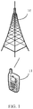
- FIG. 1 is a schematic architectural diagram of a wireless communications system according to some embodiments of this disclosure.
- the wireless communications system may include a network device 10 and a terminal.
- the terminal is marked as UE 11.
- UE 21 may perform communication (signaling transmission or data transmission) with the network device 10.
- connection between the above devices may be a wireless connection.
- a solid line is used to indicate that in FIG. 1 .
- the foregoing communications system may include a plurality of UEs 11, and that the network device 10 may communicate with the plurality of UEs 11.
- the network device 10 may be a base station.
- the base station may be a commonly used base station or an evolved node base station (evolved node base station, eNB), or may be a network device in a 5G system (for example, a next generation node base station (next generation node base station, gNB) or a transmission and reception point (transmission and reception point, TRP)), or the like.
- eNB evolved node base station
- gNB next generation node base station
- TRP transmission and reception point
- the terminal may be a mobile phone, a tablet computer, a notebook computer, an ultra-mobile personal computer (Ultra-Mobile Personal Computer, UMPC), a netbook, a personal digital assistant (Personal Digital Assistant, PDA), or the like.
- Ultra-Mobile Personal Computer Ultra-Mobile Personal Computer
- PDA Personal Digital Assistant
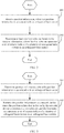
- an embodiment of this disclosure provides a method for determining an index of an orthogonal basis vector.
- the method may be performed by a network device, with specific steps as follows:
- the position information may include: at least one start index, where the start index is a start position index of a column of an orthogonal basis vector in the orthogonal basis matrix, X orthogonal basis vectors may be determined based on the start index, and X is an integer greater than zero; or the position information may include: at least one start index and at least one second index set, where the start index is a start position index of a column of an orthogonal basis vector in the orthogonal basis matrix, the second index set is a set of offset position indices of columns of a plurality of orthogonal basis vectors in the orthogonal basis matrix, X orthogonal basis vectors may be determined from d consecutive orthogonal basis vectors based on the start position index and the second index set, d and X are integers greater than zero, and d is greater than X.
- start index and the second index set are not limited in some embodiments of this disclosure.
- the first index set is associated with one or more of the start index, the second index set, an oversampling factor, an index of a layer, a row number index of a transform domain matrix, and an oversampling offset coefficient of the orthogonal basis vector.
- the oversampling offset coefficient of the orthogonal basis vector is greater than or equal to zero and less than the oversampling factor.
- one or more of the oversampling factor, the number of indices in the first index set, and the oversampling offset coefficient of the orthogonal basis vector are configured by a network side or defined by a protocol.
- the foregoing method may further include: performing modulo M with respect to the first index set (the first index set mod M) based on the position information to obtain modulo results, where M is the number of columns of the transform domain matrix.
- the foregoing method may further include: sorting the modulo results in ascending or descending order to match an order of selected transform domain matrices.
- the start index is represented as I n ,i r
- the first index set is represented as I n ,i + v r I n ,i+O ⁇ 1 + v r ... I n ,i+O ⁇ X-1 + v r
- I n ,i r represents that an index of the n th row of the transform domain matrix at the r th layer is i
- I n ,i + v r represents that an index of the n th row of the transform domain matrix at the r th layer is i + v
- I n ,i+O ⁇ 1 + v r represents that an index of the n th row of the transform domain matrix at the r th layer is i + O ⁇ 1 + ⁇
- I n ,i+o ⁇ X-1 + v r represents that an index of the n th row of the transform domain matrix at the r th
- the performing modulo M with respect to the first index set based on the position information to obtain modulo results includes at least one of the following:
- the start index is represented as I n ,i r
- the second index set is represented as I n ,i 0 + v r I n , i 1 + O ⁇ 1 + v r ... I n , i X - 1 + O ⁇ X-1 + v r
- the first index set is represented as I n , i 0 + v + i r I n , i 1 + O ⁇ 1 + v + i r ... I n , i X ⁇ 1 + O ⁇ X - 1 + v + i r
- I n ,i r represents that an index of the n th row of the transform domain matrix at the r th layer is i
- I n , i 0 + v r represents that an index of the n th row of the transform domain matrix at the r th layer is i 0 + v r
- I n ,i r represents
- values of i 0 , i 1 ... i X ⁇ 1 may be equal.
- X indices are selected from d consecutive indices starting from index i, where d is an integer greater than zero, and d is greater than X.
- the performing modulo M with respect to the first index set based on the position information to obtain modulo results includes at least one of the following:
- the determining a first index set based on the position information includes: if the number of start indices is at least one and there is only one value for the row number index n of the transform domain matrix, selecting the first index set with respect to n rows together for each layer.
- the determining a first index set based on the position information includes at least one of the following:
- the determining a first index set based on the position information includes at least one of the following:
- the set of column indices of the plurality of orthogonal basis vectors in the orthogonal basis matrix may be determined based on the received position information, which can reduce feedback overheads of the orthogonal basis vectors.
- some embodiments of this disclosure further provide a method for determining an index of an orthogonal basis vector.
- the method may be performed by a terminal, with specific steps as follows: Step 301: Determine position information, where the position information is associated with an orthogonal basis vector.
- the determining position information includes: determining a plurality of transform domain matrices; obtaining a plurality of N ⁇ M transform domain value matrices based on the plurality of transform domain matrices, where N is the number of rows of the transform domain matrix, and M is the number of columns of the transform domain matrix; obtaining a sum matrix with a length of M based on the plurality of N ⁇ M transform domain value matrices; and determining the position information based on a position index of the greatest element in the sum matrix with a length of M.
- R N ⁇ M transform domain value matrices may be obtained based on R transform domain matrices, where N is the number of rows of a transform domain matrix, M is the number of columns of the transform domain matrix; and R is the total number of layers.
- the position information is determined based on a maximum value of an index position element in the n th row of the sum matrix at the r th layer, or a maximum sum of X consecutive elements starting from the start position, or a maximum sum of d consecutive elements starting from the start position.
- Step 302 Transmit the position information to a network device, where the position information is for use by the network device to determine a first index set, and the first index set represents a set of column indices of a plurality of orthogonal basis vectors in an orthogonal basis matrix.
- the position information may include: at least one start index, where the start index is a start position index of a column of an orthogonal basis vector in the orthogonal basis matrix, X orthogonal basis vectors may be determined based on the start index, and X is an integer greater than zero; or the position information may include: at least one start index and at least one second index set, where the start index is a start position index of a column of an orthogonal basis vector in the orthogonal basis matrix, the second index set is a set of offset position indices of columns of a plurality of orthogonal basis vectors in the orthogonal basis matrix, X orthogonal basis vectors may be determined from d consecutive orthogonal basis vectors based on the start position index and the second index set, d and X are integers greater than zero, and d is greater than X.
- the first index set is associated with one or more of the start index, the second index set, an oversampling factor, an index of a layer, a row number index of a transform domain matrix, and an oversampling offset coefficient of the orthogonal basis vector.
- the oversampling offset coefficient of the orthogonal basis vector is greater than or equal to zero and less than the oversampling factor.
- the method may further include: transmitting one or more of the oversampling factor, the number of indices in the first index set, and the oversampling offset coefficient of the orthogonal basis vector to the network device.
- the start index is represented as I n ,i r
- the first index set is represented as I n , i + v r I n , i + O ⁇ 1 + v r ⁇ I n , i + O ⁇ X ⁇ 1 + v r ; and I n ,i r
- the start index is represented as I n ,i r
- the second index set is represented as I n , i 0 + v r I n , i 1 + O ⁇ 1 + v r ⁇ I n , i X ⁇ 1 + O ⁇ X ⁇ 1 + v r
- the first index set is represented as I n , i 0 + v + i r I n , i 1 + O ⁇ 1 + v + i r ⁇ I n , i X ⁇ 1 + O ⁇ X ⁇ 1 + v + i r ;
- values of i 0 , i 1 ... i X ⁇ 1 may be equal.
- X indices are selected from d consecutive indices starting from index i, where d is an integer greater than zero, and d is greater than X.
- the foregoing method further includes: determining the first index set based on the position information, and sorting indices in the first index set in ascending or descending order; determining a corresponding feedback matrix based on the transform domain matrix and the sorted first index set; and transmitting the feedback matrix to the network device.
- an element in the n th row and the c th column in the feedback matrix is an element in the n th row and the x th column of the transform domain matrix at the r th layer, where x is the c th element of the n th first index set at the r th layer.
- elements in all rows and the c th column in the feedback matrix are elements in the x th column of the transform domain matrix at the r th layer, where x is the c th element of the first index set at the r th layer.
- the terminal may report the position information to the network device, so that the network device can determine the set of column indices of the plurality of orthogonal basis vectors in the orthogonal basis matrix based on the received position information, which can reduce feedback overheads of the orthogonal basis vectors.
- scenario 1 selecting a plurality of consecutive orthogonal basis vectors
- scenario 2 selecting a plurality of orthogonal basis vectors from a plurality of consecutive orthogonal basis vectors.
- Scenario 1 Selecting X consecutive orthogonal basis vectors:
- the terminal reports at least one start position I n , i r .
- Indices of the X orthogonal basis vectors selected by a network side for restoring a coefficient matrix are I n , i + v r I n , i + O ⁇ 1 + v r ⁇ I n , i + O ⁇ X ⁇ 1 + v r , where
- a value of O may be configured by the network side or defined by a protocol. It should be understood that in some embodiments of this disclosure, a value range of O and a determining manner of the specific value are not specifically limited.
- a value of v may be determined in the following manner:
- a value range of v and a determining manner of the specific value are not specifically limited.
- a value of X may be determined in the following manner:
- modulo M is performed with respect to indices satisfying I n , i + v r I n , i + O ⁇ 1 + v r ⁇ I n , i + O ⁇ X ⁇ 1 + v r > M ⁇ 1 , or modulo M is directly performed with respect to I n , i + v r I n , i + O ⁇ 1 + v r ⁇ I n , i + O ⁇ X ⁇ 1 + v r , to obtain I ⁇ n , i + v r I ⁇ n , i + O ⁇ 1 + v r ⁇ I ⁇ n , i + O ⁇ X ⁇ 1 + v r .
- modulo (M+1) is performed with respect to indices satisfying I n , i + v r I n , i + O ⁇ 1 + v r ⁇ I n , i + O ⁇ X ⁇ 1 + v r > M , or modulo (M+1) is directly performed with respect to I n , i + v r I n , i + O ⁇ 1 + v r ⁇ I n , i + O ⁇ X ⁇ 1 + v r , to obtain I ⁇ n , i + v r I ⁇ n , i + O ⁇ 1 + v r ⁇ I ⁇ n , i + O ⁇ X ⁇ 1 + v r .
- M is the number of columns of the transform domain matrix.
- the network side may sort I ⁇ n , i + v r I ⁇ n , i + O ⁇ 1 + v r ⁇ I ⁇ n , i + O ⁇ X ⁇ 1 + v r in ascending or descending order after the modulo operation is completed, to match an order of the selected transform domain matrices.
- the network side may repeat the foregoing modulo steps or the modulo and sorting steps.
- the orthogonal basis index may be selected in the following ways:
- Scenario 2 Selecting X orthogonal basis vectors from d consecutive orthogonal basis vectors:
- the terminal reports at least one start position I n , i r and at least one group of index positions I n , i 0 + v r I n , i 1 + O ⁇ 1 + v r ⁇ I n , i X ⁇ 1 + O ⁇ X ⁇ 1 + v r .
- Indices of the orthogonal basis vectors selected by a network side for restoring a coefficient matrix are I n , i 0 + v + i r I n , i 1 + O ⁇ 1 + v + i r ⁇ I n , i X ⁇ 1 + O ⁇ X ⁇ 1 + v + i r , where
- a value of O may be configured by the network side or defined by a protocol. It should be understood that in some embodiments of this disclosure, a value range of O and a determining manner of the specific value are not specifically limited.
- a value of v may be determined in the following manner:
- a value range of v and a determining manner of the specific value are not specifically limited.
- a value of X may be determined in the following manner:
- a value range of X and a determining manner of the specific value are not specifically limited.
- values of i 0 , i 1 ...i X ⁇ 1 may be equal.
- X indices are selected from d consecutive indices starting from index i, where d is an integer greater than zero, and d is greater than X.
- a value of d may be determined in the following manner:
- modulo M is performed with respect to indices satisfying I n , i 0 + v + i r I n , i 1 + O ⁇ 1 + v + i r ⁇ I n , i X ⁇ 1 + O ⁇ X ⁇ 1 + v + i r > M ⁇ 1 , or modulo M is directly performed with respect to I n , i 0 + v + i r I n , i 1 + O ⁇ 1 + v + i r ⁇ I n , i X ⁇ 1 + O ⁇ X ⁇ 1 + v + i r , to obtain [ I ⁇ n , i 0 + v + i r I ⁇ n , i 1 + O ⁇ 1 + v + i r ⁇ I ⁇ n , i X ⁇ 1 , i X ⁇ 1 , to obtain [ I ⁇ n , i
- modulo (M+1) is performed with respect to indices satisfying I n , i 0 + v + i r I n , i 1 + O ⁇ 1 + v + i r ⁇ I n , i X ⁇ 1 + O ⁇ X ⁇ 1 + v + i r > M , or modulo (M+1) is directly performed with respect to I n , i 0 + v + i r I n , i 1 + O ⁇ 1 + v + i r ⁇ I n , i X ⁇ 1 + O ⁇ X ⁇ 1 + v + i r , to obtain I ⁇ n , i 0 + v + i r I ⁇ n , i 1 + O ⁇ 1 + v + i r ⁇ I ⁇ n , i X ⁇ 1 + O ⁇ X ⁇ 1 + v + i r , to obtain I
- M is the number of columns of the transform domain matrix.
- the network side may sort I ⁇ n , i 0 + v + i r I ⁇ n , i 1 + O ⁇ 1 + v + i r ⁇ I ⁇ n , i X ⁇ 1 + O ⁇ X ⁇ 1 + v + i r in ascending or descending order after the modulo operation is completed, to match an order of the selected transform domain matrices.
- the orthogonal basis index may be selected in the following ways:
- a value of X may be determined in the following manner:
- a value range of X and a determining manner of the specific value are not specifically limited.
- a value of X may be determined in the following manner:
- a value range of X and a determining manner of the specific value are not specifically limited.
- a network device is further provided. Because a problem resolving principle of the network device is similar to the method for determining an index of an orthogonal basis vector in some embodiments of this disclosure, for the implementation of the network device, reference may be made to the implementation of the method, and details are not repeated.
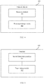
- some embodiments of this disclosure further provide a network device, where the network device 400 includes:
- the position information may include: at least one start index, where the start index is a start position index of a column of an orthogonal basis vector in the orthogonal basis matrix; or the position information includes at least one start index and at least one second index set, where the start index is a start position index of a column of an orthogonal basis vector in the orthogonal basis matrix, and the second index set is a set of offset position indices of a plurality of orthogonal basis vectors in columns of the orthogonal basis matrix relative to the start index.
- the first index set is associated with one or more of the start index, the second index set, an oversampling factor, an index of a layer, a row number index of a transform domain matrix, and an oversampling offset coefficient of the orthogonal basis vector, where the oversampling offset coefficient of the orthogonal basis vector is greater than or equal to zero and less than the oversampling factor.
- one or more of the oversampling factor, the number of indices in the first index set, and the oversampling offset coefficient of the orthogonal basis vector may be configured by the network side or defined by a protocol.
- the network device 400 may further include a modulo module, configured to perform modulo M with respect to the first index set based on the position information to obtain modulo results, where M is the number of columns of the transform domain matrix.
- the network device 400 may further include a sorting module, configured to sort the modulo results in ascending or descending order to match an order of selected transform domain matrices.
- the start index is represented as I n ,i r
- the first index set is represented as I n ,i + v r I n ,i + O ⁇ 1 + v r ... I n ,i + O ⁇ X ⁇ 1 + v r ;
- the modulo module further executes at least one of the following:
- the start index is represented as I n ,i r
- the second index set is represented as I n , i 0 + v r I n , i 1 + O ⁇ 1 + v r ... I n , i X ⁇ 1 + O ⁇ X ⁇ 1 + v r
- the first index set is represented as I n , i 0 + v + i r I n , i 1 + O ⁇ 1 + v + i r ... I n , i X ⁇ 1 + O ⁇ X ⁇ 1 + v + i r ;
- values of i 0 , i 1 ... i X ⁇ 1 may be equal.
- X indices are selected from d consecutive indices starting from index i, where d is an integer greater than zero, and d is greater than X.
- the modulo module further executes at least one of the following:
- mod (a, b) is a mod b, or a mod b.
- the first determining module 402 is further configured to: if the number of start indices is at least one and there is only one value for the row number index n of the transform domain matrix, select the first index set with respect to n rows together for each layer.
- the first determining module 402 is further configured to execute at least one of the following:
- the first determining module 402 is further configured to:
- the network device provided according to some embodiments of this disclosure may execute the above method embodiment, with a similar implementation principle and similar technical effects. Details are not repeated herein in this embodiment.
- Some embodiments of this disclosure further provide a terminal. Because a problem resolving principle of the terminal is similar to the method for determining an index of an orthogonal basis vector in some embodiments of this disclosure, for implementation of the terminal, reference may be made to implementation of the method, and details are not described herein again.
- some embodiments of this disclosure further provide a terminal, and the terminal 400 includes:
- the second determining module 501 is further configured to: determine a plurality of transform domain matrices; obtain a plurality of N ⁇ M transform domain value matrices based on the plurality of transform domain matrices, where N is the number of rows of the transform domain matrix, and M is the number of columns of the transform domain matrix; obtain a sum matrix with a length of M based on the plurality of N ⁇ M transform domain value matrices; and determine the position information based on a position index of the greatest element in the sum matrix with a length of M.
- the position information may include: at least one start index, where the start index is a start position index of a column of an orthogonal basis vector in the orthogonal basis matrix, X orthogonal basis vectors may be determined based on the start index, and X is an integer greater than zero; or the position information may include: at least one start index and at least one second index set, where the start index is a start position index of a column of an orthogonal basis vector in the orthogonal basis matrix, the second index set is a set of offset position indices of columns of a plurality of orthogonal basis vectors in the orthogonal basis matrix, X orthogonal basis vectors may be determined from d consecutive orthogonal basis vectors based on the start position index and the second index set, d and X are integers greater than zero, and d is greater than X.
- the first index set is associated with one or more of the start index, the second index set, an oversampling factor, an index of a layer, a row number index of a transform domain matrix, and an oversampling offset coefficient of the orthogonal basis vector.
- the oversampling offset coefficient of the orthogonal basis vector is greater than or equal to zero and less than the oversampling factor.
- the transmitting module 502 is further configured to: transmit one or more of the oversampling factor, the number of indices in the first index set, and the oversampling offset coefficient of the orthogonal basis vector to the network device.
- the start index is represented as I n ,i r
- the first index set is represented as I n , i + v r I n , i + O ⁇ 1 + v r ... I n , i + O ⁇ X ⁇ 1 + v r ;
- the start index is represented as I n ,i r
- the second index set is represented as I n , i 0 + v r I n , i 1 + O ⁇ 1 + v r ... I n , i X ⁇ 1 + O ⁇ X ⁇ 1 + v r
- the first index set is represented as I n , i 0 + v + i r I n , i 1 + O ⁇ 1 + v + i r ⁇ I n , i X ⁇ 1 + O ⁇ X ⁇ 1 + v + i r ;
- values of i 0 , i 1 ... i X ⁇ 1 may be equal.
- X indices are selected from d consecutive indices starting from index i, where d is an integer greater than zero, and d is greater than X.
- the terminal further includes a third determining module, configured to: determine the first index set based on the position information, and sort indices in the first index set in ascending or descending order; determine a corresponding feedback matrix based on the transform domain matrix and the sorted first index set; and transmit the feedback matrix to the network device.
- a third determining module configured to: determine the first index set based on the position information, and sort indices in the first index set in ascending or descending order; determine a corresponding feedback matrix based on the transform domain matrix and the sorted first index set; and transmit the feedback matrix to the network device.
- the terminal provided in some embodiments of this disclosure may execute the foregoing method embodiments, implementation principles and technical effects thereof are similar, and details are not described herein again in this embodiment.
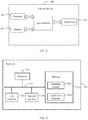
- FIG. 6 is a structural diagram of a network device applied to some embodiments of this disclosure.
- the network device 600 includes a processor 601, a transceiver 602, a memory 603, and a bus interface.
- the network device 600 further includes a program stored in the memory 603 and capable of running on the processor 601, where when the program is executed by the processor 601, the following step is implemented: receiving position information, where the position information is associated with an orthogonal basis vector; and determining at least one first index set based on the position information, where the first index set represents a set of column indices of a plurality of orthogonal basis vectors in an orthogonal basis matrix.
- a bus architecture may include any quantity of interconnected buses and bridges, and specifically connect together various circuits of one or more processors represented by the processor 601 and a memory represented by the memory 603.
- the bus architecture may further interconnect various other circuits such as a peripheral device, a voltage regulator, and a power management circuit. These are all well known in the art, and therefore are not further described in this specification.
- the bus interface provides interfaces.
- the transceiver 602 may be a plurality of components, including a transmitter and a receiver, and provides units for communicating with a variety of other apparatuses on a transmission medium.
- the processor 601 is responsible for management of the bus architecture and general processing, and the memory 603 may store data for use by the processor 601 when the processor 601 performs an operation.
- the network device provided according to some embodiments of this disclosure may execute the above method embodiment, with a similar implementation principle and similar technical effects. Details are not repeated herein in this embodiment.
- a terminal 700 shown in FIG. 7 includes at least one processor 701, a memory 702, at least one network interface 704, and a user interface 703. Components of the terminal 700 are coupled together by using a bus system 705. It can be understood that the bus system 705 is configured to implement connection and communication between these components. In addition to a data bus, the bus system 705 further includes a power bus, a control bus, and a status signal bus. However, for clarity of description, various buses are marked as the bus system 705 in FIG. 7 .
- the user interface 703 may include a display, a keyboard, or a pointing device (for example, a mouse, a trackball (trackball), a touch panel, or a touchscreen).
- a pointing device for example, a mouse, a trackball (trackball), a touch panel, or a touchscreen.
- the memory 702 in some embodiments of this disclosure may be a volatile memory or a non-volatile memory, or may include both a volatile memory and a non-volatile memory.
- the non-volatile memory may be a read-only memory (Read-Only Memory, ROM), a programmable read-only memory (Programmable ROM, PROM), an erasable programmable read-only memory (Erasable PROM, EPROM), an electrically erasable programmable read-only memory (Electrically EPROM, EEPROM), or a flash memory.
- the volatile memory may be a random access memory (Random Access Memory, RAM), which is used as an external cache.
- RAM any forms of RAM may be used, for example, a static random access memory (Static RAM, SRAM), a dynamic random access memory (Dynamic RAM, DRAM), a synchronous dynamic random access memory (Synchronous DRAM, SDRAM), a double data rate synchronous dynamic random access memory (Double Data Rate SDRAM, DDRSDRAM), an enhanced synchronous dynamic random access memory (Enhanced SDRAM, ESDRAM), a synchronous link dynamic random access memory (Synchlink DRAM, SLDRAM), and a direct rambus random access memory (Direct Rambus RAM, DRRAM).
- Static RAM, SRAM static random access memory
- DRAM dynamic random access memory
- DRAM synchronous dynamic random access memory
- SDRAM double data rate synchronous dynamic random access memory
- Double Data Rate SDRAM Double Data Rate SDRAM
- ESDRAM enhanced synchronous dynamic random access memory
- Synchlink DRAM synchronous link dynamic random access memory
- Direct Rambus RAM Direct Rambus RAM
- the memory 702 stores the following elements: executable modules or data structures, or a subset thereof, or an extended set thereof: an operating system 7021 and an application program 7022.
- the operating system 7021 includes various system programs, such as a framework layer, a core library layer, and a driver layer, for implementing various basic services and processing hardware-based tasks.
- the application program 7022 includes various application programs, such as a media player (Media Player) and a browser (Browser), which are used to implement various application services.
- a program for implementing the method in some embodiments of this disclosure may be included in the application program 5022.
- the program or instruction stored in the memory 702 is invoked to perform the steps of determining position information related to an orthogonal basis vector; transmitting the position information to a network device, where the position information is for use by the network device to determine at least one first index set, and the first index set represents a set of column indices of a plurality of orthogonal basis vectors in an orthogonal basis matrix.
- the terminal provided in some embodiments of this disclosure may execute the foregoing method embodiments, implementation principles and technical effects thereof are similar, and details are not described herein again in this embodiment.
- the software instruction may include a corresponding software module.
- the software module may be stored in a RAM, a flash memory, a ROM, an EPROM, an EEPROM, a register, a hard disk, a removable hard disk, a CD-ROM, or a storage medium of any other form known in the art.
- a storage medium is coupled to the processor, enabling the processor to read information from the storage medium or write information into the storage medium.
- the storage medium may be a component of the processor.
- the processor and the storage medium may be located in an ASIC.
- the ASIC may be located in a core network interface device.
- the processor and the storage medium may exist in the core network interface device as discrete components.
- the computer-readable medium includes a computer storage medium and a communication medium, where the communication medium includes any medium that enables a computer program to be transmitted from one place to another place.
- the storage medium may be any available medium accessible by a general-purpose or dedicated computer.
- some embodiments of this disclosure may be provided as a method, a system, or a computer program product. Therefore, some embodiments of this disclosure may be hardware-only embodiments, software-only embodiments, or embodiments with a combination of software and hardware. Moreover, some embodiments of this disclosure may be implemented in the form of one or more computer program products implemented on a computer-usable storage medium (including but not limited to a disk memory, a CD-ROM, an optical memory, and the like) that includes computer-usable program code.
- a computer-usable storage medium including but not limited to a disk memory, a CD-ROM, an optical memory, and the like
- These computer program instructions may be provided to a general-purpose computer, a special-purpose computer, an embedded processor, or a processor of any other programmable data processing device to generate a machine, so that the instructions executed by a computer or a processor of any other programmable data processing device generate an apparatus for implementing a specific function in one or more processes in the flowcharts and/or in one or more blocks in the block diagrams.
- These computer program instructions may be stored in a computer-readable memory that can instruct the computer or any other programmable data processing device to work in a specific manner, so that the instructions stored in the computer-readable memory generate an artifact that includes an instruction apparatus.
- the instruction apparatus implements a specific function in one or more processes in the flowcharts and/or in one or more blocks in the block diagrams.
- These computer program instructions may be loaded onto a computer or another programmable data processing device, so that a series of operations and steps are performed on the computer or the another programmable device, thereby generating computer-implemented processing. Therefore, the instructions executed on the computer or the another programmable device provide steps for implementing a specific function in one or more processes in the flowcharts and/or in one or more blocks in the block diagrams.
Landscapes
- Engineering & Computer Science (AREA)
- Computer Networks & Wireless Communication (AREA)
- Signal Processing (AREA)
- Physics & Mathematics (AREA)
- Mathematical Physics (AREA)
- Mobile Radio Communication Systems (AREA)
- Compression, Expansion, Code Conversion, And Decoders (AREA)
- Compression Or Coding Systems Of Tv Signals (AREA)
Applications Claiming Priority (2)
| Application Number | Priority Date | Filing Date | Title |
|---|---|---|---|
| CN201811527399.3A CN111262611B (zh) | 2018-12-13 | 2018-12-13 | 确定正交基向量的索引的方法和设备 |
| PCT/CN2019/106940 WO2020119211A1 (fr) | 2018-12-13 | 2019-09-20 | Procédé et dispositif de détermination d'un indice de vecteur de base orthogonale |
Publications (2)
| Publication Number | Publication Date |
|---|---|
| EP3896867A1 true EP3896867A1 (fr) | 2021-10-20 |
| EP3896867A4 EP3896867A4 (fr) | 2022-02-09 |
Family
ID=70950697
Family Applications (1)
| Application Number | Title | Priority Date | Filing Date |
|---|---|---|---|
| EP19896912.3A Pending EP3896867A4 (fr) | 2018-12-13 | 2019-09-20 | Procédé et dispositif de détermination d'un indice de vecteur de base orthogonale |
Country Status (8)
| Country | Link |
|---|---|
| US (1) | US11509374B2 (fr) |
| EP (1) | EP3896867A4 (fr) |
| JP (1) | JP7216825B2 (fr) |
| KR (1) | KR102528941B1 (fr) |
| CN (1) | CN111262611B (fr) |
| MY (1) | MY209405A (fr) |
| SG (1) | SG11202106208TA (fr) |
| WO (1) | WO2020119211A1 (fr) |
Families Citing this family (8)
| Publication number | Priority date | Publication date | Assignee | Title |
|---|---|---|---|---|
| WO2020144542A1 (fr) | 2019-01-11 | 2020-07-16 | Lenovo (Singapore) Pte. Ltd. | Compression par livre de codes de type 2 avec quantification à plusieurs étapes |
| US12177707B2 (en) * | 2019-07-19 | 2024-12-24 | Ntt Docomo, Inc. | Terminal and radio communication method |
| CN114598365B (zh) | 2020-12-01 | 2023-10-17 | 维沃移动通信有限公司 | 传输方法、装置、设备及可读存储介质 |
| CN115441914A (zh) * | 2021-06-01 | 2022-12-06 | 华为技术有限公司 | 一种通信方法及装置 |
| CN116684916A (zh) * | 2022-02-22 | 2023-09-01 | 维沃移动通信有限公司 | Csi上报方法、信道预测方法、终端和网络侧设备 |
| CN116939650B (zh) * | 2022-04-01 | 2025-09-19 | 维沃移动通信有限公司 | 信道特征信息传输方法、装置、终端及网络侧设备 |
| CN118784016A (zh) * | 2023-04-03 | 2024-10-15 | 维沃移动通信有限公司 | 预编码矩阵指示pmi参数的反馈方法、pmi参数的反馈方法 |
| WO2025039102A1 (fr) * | 2023-08-18 | 2025-02-27 | Qualcomm Incorporated | Décalage de suréchantillonnage de domaine fréquentiel (fd) pour des informations d'état de canal dans des communications sans fil |
Family Cites Families (12)
| Publication number | Priority date | Publication date | Assignee | Title |
|---|---|---|---|---|
| CN102006108B (zh) * | 2009-08-28 | 2012-10-03 | 华为技术有限公司 | 信道状态信息的传输方法、装置和系统 |
| CA2826243C (fr) * | 2011-02-01 | 2016-06-21 | Research In Motion Limited | Programme d'alignement d'interferences multi-utilisateurs d'element de liaison descendante de rang mixte |
| JP5432208B2 (ja) * | 2011-04-25 | 2014-03-05 | 株式会社Nttドコモ | 移動通信端末 |
| CN103516494B (zh) * | 2012-06-21 | 2016-12-21 | 华为技术有限公司 | 信道信息反馈方法和用户设备 |
| CN103560983B (zh) * | 2013-10-15 | 2017-04-12 | 北京航空航天大学 | 一种以用户为中心多基站协作系统中的训练序列设计方法 |
| US9825742B2 (en) * | 2014-10-03 | 2017-11-21 | Samsung Electronics Co., Ltd. | Codebook design and structure for advanced wireless communication systems |
| US9800305B2 (en) * | 2014-11-07 | 2017-10-24 | Electronics And Telecommunications Research Institute | Terminal and operation method thereof in multi-user multi-input multi-output system |
| EP4068662A1 (fr) * | 2015-07-12 | 2022-10-05 | Cohere Technologies, Inc. | Système de communication sur l'espace temps-fréquence orthogonal compatible avec ofdm |
| CN106209193B (zh) * | 2016-08-19 | 2019-05-24 | 西华大学 | 基于压缩感知大规模mimo系统的csi反馈方法 |
| WO2018143667A1 (fr) * | 2017-01-31 | 2018-08-09 | 엘지전자 주식회사 | Procédé permettant de transmettre périodiquement des informations de commande de liaison montante dans un système de communication sans fil et appareil associé |
| CN107453797B (zh) * | 2017-08-18 | 2020-04-07 | 清华大学 | 不依赖导频的多天线基站发射方法和设备 |
| KR101995882B1 (ko) * | 2017-10-11 | 2019-07-04 | 서울대학교산학협력단 | 시분할 이중통신 시스템에서 상향링크 전송 방법 및 장치 |
-
2018
- 2018-12-13 CN CN201811527399.3A patent/CN111262611B/zh active Active
-
2019
- 2019-09-20 SG SG11202106208TA patent/SG11202106208TA/en unknown
- 2019-09-20 KR KR1020217021294A patent/KR102528941B1/ko active Active
- 2019-09-20 MY MYPI2021003164A patent/MY209405A/en unknown
- 2019-09-20 JP JP2021533653A patent/JP7216825B2/ja active Active
- 2019-09-20 EP EP19896912.3A patent/EP3896867A4/fr active Pending
- 2019-09-20 WO PCT/CN2019/106940 patent/WO2020119211A1/fr not_active Ceased
-
2021
- 2021-06-11 US US17/346,072 patent/US11509374B2/en active Active
Also Published As
| Publication number | Publication date |
|---|---|
| CN111262611A (zh) | 2020-06-09 |
| WO2020119211A1 (fr) | 2020-06-18 |
| MY209405A (en) | 2025-07-07 |
| JP2022514516A (ja) | 2022-02-14 |
| US11509374B2 (en) | 2022-11-22 |
| EP3896867A4 (fr) | 2022-02-09 |
| US20210306048A1 (en) | 2021-09-30 |
| CN111262611B (zh) | 2021-07-06 |
| KR102528941B1 (ko) | 2023-05-03 |
| SG11202106208TA (en) | 2021-07-29 |
| JP7216825B2 (ja) | 2023-02-01 |
| KR20210100683A (ko) | 2021-08-17 |
Similar Documents
| Publication | Publication Date | Title |
|---|---|---|
| US11509374B2 (en) | Method for determining index of orthogonal basis vector and device | |
| JP7457698B2 (ja) | Csiフィードバックおよび受信方法、装置、デバイス、および記憶媒体 | |
| JP7450625B2 (ja) | 無線通信ネットワークにおけるフィードバック報告のための方法および装置 | |
| CN105450273B (zh) | 一种传输编码指示信息和确定预编码矩阵的方法和装置 | |
| EP3787200B1 (fr) | Procédé de réception d'informations d'état de canal et dispositif | |
| CN107196749B (zh) | 一种信道状态信息测量、参考信号的发送方法和装置 | |
| EP4106221A1 (fr) | Procédé de rétroaction d'informations d'état de canal, dispositif, terminal, côté réseau, et support de stockage | |
| EP3522677A1 (fr) | Procédé et dispositif pour transmettre des informations d'état de canal | |
| US10879971B2 (en) | Methods and apparatuses for transmitting pre-coding indication information and determining pre-coding matrix | |
| CN111800172B (zh) | 一种通信方法及装置 | |
| EP2996272A1 (fr) | Procédé de retour d'information, équipement d'utilisateur et station de base | |
| CN111436075B (zh) | 信道状态信息的上报方法、解码方法、终端及网络侧设备 | |
| CN110474665A (zh) | 信道估计方法和装置 | |
| US12040855B2 (en) | Frequency time domain channel hardening and overhead reduction | |
| WO2018027813A1 (fr) | Procédé et appareil de rapport de paramètres de rétroaction | |
| CN111277379B (zh) | 无线通信方法和终端设备 | |
| RU2766559C1 (ru) | Способ и устройство для передачи и приема информации о состоянии канала, узел связи и носитель данных | |
| WO2023104205A1 (fr) | Procédé de rétroaction, procédé d'acquisition, procédé d'apprentissage, terminal, station de base, dispositif électronique et support | |
| EP3389193A1 (fr) | Procédé et appareil pour déterminer une matrice de précodage |
Legal Events
| Date | Code | Title | Description |
|---|---|---|---|
| STAA | Information on the status of an ep patent application or granted ep patent |
Free format text: STATUS: THE INTERNATIONAL PUBLICATION HAS BEEN MADE |
|
| PUAI | Public reference made under article 153(3) epc to a published international application that has entered the european phase |
Free format text: ORIGINAL CODE: 0009012 |
|
| STAA | Information on the status of an ep patent application or granted ep patent |
Free format text: STATUS: REQUEST FOR EXAMINATION WAS MADE |
|
| 17P | Request for examination filed |
Effective date: 20210617 |
|
| AK | Designated contracting states |
Kind code of ref document: A1 Designated state(s): AL AT BE BG CH CY CZ DE DK EE ES FI FR GB GR HR HU IE IS IT LI LT LU LV MC MK MT NL NO PL PT RO RS SE SI SK SM TR |
|
| A4 | Supplementary search report drawn up and despatched |
Effective date: 20220111 |
|
| RIC1 | Information provided on ipc code assigned before grant |
Ipc: H04B 7/0456 20170101ALI20220104BHEP Ipc: H04B 7/06 20060101AFI20220104BHEP |
|
| DAV | Request for validation of the european patent (deleted) | ||
| DAX | Request for extension of the european patent (deleted) | ||
| STAA | Information on the status of an ep patent application or granted ep patent |
Free format text: STATUS: EXAMINATION IS IN PROGRESS |
|
| RIC1 | Information provided on ipc code assigned before grant |
Ipc: H04B 7/0456 20170101ALI20230921BHEP Ipc: H04B 7/06 20060101AFI20230921BHEP |
|
| 17Q | First examination report despatched |
Effective date: 20231016 |