EP3897009B1 - Procédé et dispositif de surveillance - Google Patents
Procédé et dispositif de surveillance Download PDFInfo
- Publication number
- EP3897009B1 EP3897009B1 EP21178665.2A EP21178665A EP3897009B1 EP 3897009 B1 EP3897009 B1 EP 3897009B1 EP 21178665 A EP21178665 A EP 21178665A EP 3897009 B1 EP3897009 B1 EP 3897009B1
- Authority
- EP
- European Patent Office
- Prior art keywords
- communication
- communication circuit
- monitoring
- monitoring data
- data
- Prior art date
- Legal status (The legal status is an assumption and is not a legal conclusion. Google has not performed a legal analysis and makes no representation as to the accuracy of the status listed.)
- Active
Links
Images

Classifications
-
- G—PHYSICS
- G05—CONTROLLING; REGULATING
- G05D—SYSTEMS FOR CONTROLLING OR REGULATING NON-ELECTRIC VARIABLES
- G05D1/00—Control of position, course, altitude or attitude of land, water, air or space vehicles, e.g. using automatic pilots
- G05D1/0011—Control of position, course, altitude or attitude of land, water, air or space vehicles, e.g. using automatic pilots associated with a remote control arrangement
- G05D1/0022—Control of position, course, altitude or attitude of land, water, air or space vehicles, e.g. using automatic pilots associated with a remote control arrangement characterised by the communication link
-
- G—PHYSICS
- G05—CONTROLLING; REGULATING
- G05D—SYSTEMS FOR CONTROLLING OR REGULATING NON-ELECTRIC VARIABLES
- G05D1/00—Control of position, course, altitude or attitude of land, water, air or space vehicles, e.g. using automatic pilots
- G05D1/10—Simultaneous control of position or course in three dimensions
-
- G—PHYSICS
- G05—CONTROLLING; REGULATING
- G05D—SYSTEMS FOR CONTROLLING OR REGULATING NON-ELECTRIC VARIABLES
- G05D1/00—Control of position, course, altitude or attitude of land, water, air or space vehicles, e.g. using automatic pilots
- G05D1/10—Simultaneous control of position or course in three dimensions
- G05D1/101—Simultaneous control of position or course in three dimensions specially adapted for aircraft
-
- G—PHYSICS
- G05—CONTROLLING; REGULATING
- G05D—SYSTEMS FOR CONTROLLING OR REGULATING NON-ELECTRIC VARIABLES
- G05D1/00—Control of position, course, altitude or attitude of land, water, air or space vehicles, e.g. using automatic pilots
- G05D1/40—Control within particular dimensions
- G05D1/46—Control of position or course in three dimensions [3D]
-
- G—PHYSICS
- G08—SIGNALLING
- G08C—TRANSMISSION SYSTEMS FOR MEASURED VALUES, CONTROL OR SIMILAR SIGNALS
- G08C17/00—Arrangements for transmitting signals characterised by the use of a wireless electrical link
- G08C17/02—Arrangements for transmitting signals characterised by the use of a wireless electrical link using a radio link
-
- H—ELECTRICITY
- H04—ELECTRIC COMMUNICATION TECHNIQUE
- H04B—TRANSMISSION
- H04B7/00—Radio transmission systems, i.e. using radiation field
- H04B7/14—Relay systems
- H04B7/15—Active relay systems
- H04B7/185—Space-based or airborne stations; Stations for satellite systems
- H04B7/18502—Airborne stations
- H04B7/18506—Communications with or from aircraft, i.e. aeronautical mobile service
-
- H—ELECTRICITY
- H04—ELECTRIC COMMUNICATION TECHNIQUE
- H04W—WIRELESS COMMUNICATION NETWORKS
- H04W24/00—Supervisory, monitoring or testing arrangements
- H04W24/10—Scheduling measurement reports ; Arrangements for measurement reports
-
- H—ELECTRICITY
- H04—ELECTRIC COMMUNICATION TECHNIQUE
- H04W—WIRELESS COMMUNICATION NETWORKS
- H04W4/00—Services specially adapted for wireless communication networks; Facilities therefor
- H04W4/30—Services specially adapted for particular environments, situations or purposes
- H04W4/40—Services specially adapted for particular environments, situations or purposes for vehicles, e.g. vehicle-to-pedestrians [V2P]
- H04W4/44—Services specially adapted for particular environments, situations or purposes for vehicles, e.g. vehicle-to-pedestrians [V2P] for communication between vehicles and infrastructures, e.g. vehicle-to-cloud [V2C] or vehicle-to-home [V2H]
-
- H—ELECTRICITY
- H04—ELECTRIC COMMUNICATION TECHNIQUE
- H04W—WIRELESS COMMUNICATION NETWORKS
- H04W72/00—Local resource management
- H04W72/04—Wireless resource allocation
- H04W72/044—Wireless resource allocation based on the type of the allocated resource
-
- H—ELECTRICITY
- H04—ELECTRIC COMMUNICATION TECHNIQUE
- H04W—WIRELESS COMMUNICATION NETWORKS
- H04W72/00—Local resource management
- H04W72/50—Allocation or scheduling criteria for wireless resources
- H04W72/54—Allocation or scheduling criteria for wireless resources based on quality criteria
- H04W72/542—Allocation or scheduling criteria for wireless resources based on quality criteria using measured or perceived quality
-
- H—ELECTRICITY
- H04—ELECTRIC COMMUNICATION TECHNIQUE
- H04W—WIRELESS COMMUNICATION NETWORKS
- H04W4/00—Services specially adapted for wireless communication networks; Facilities therefor
- H04W4/02—Services making use of location information
- H04W4/029—Location-based management or tracking services
Definitions
- the present disclosure relates to communication technologies and, more particularly, to a monitoring method and device using multiple communication circuits.
- UAVs unmanned aerial vehicles
- safety issues and challenges arise.
- UAVs systems may potentially be used for invading privacy, or carrying out terrorist and/or criminal activities.
- Conventional methods of detecting or monitoring a UAV include, for example, using a radar for detecting an object, which is limited by the UAV size or material of the UAV; recognizing a sound generated by a UAV, which requires a large amount of data processing; and performing visual detection techniques, which does not work well in distinguishing a UAV from other movable objects.
- CN 107223223 A discloses a control method and a system of a unmanned aerial vehicle flying at first visual angle, and intelligent glasses.
- the control system of the unmanned aerial vehicle includes a remote controller and intelligent glasses, wherein the intelligent glasses can directly establish a first channel with the unmanned aerial vehicle in case no remote controller performs relay so as to enable the intelligent glasses to receive first visual angle image data from the unmanned aerial vehicle through the first channel and display the first angle image data.
- the remote controller can directly establish a second channel with the unmanned aerial vehicle in case no intelligent glasses perform relay so as to enable the remote controller to directly transmit a first flying control command to the unmanned aerial vehicle through the second channel.
- the control system herein can directly control the unmanned aerial vehicle in case of no requirement for relays, avoids delay of image transmission and operation signals, and increases control accuracy.
- a method for video broadcasting may comprise: receiving broadcast data from a broadcasting end, wherein the broadcast data comprises video data collected by a plurality of unmanned aerial vehicles (UAVs), and wherein said UAVs are configured to be (1) operated in a coordinated manner and (2) in communication with one or more ground stations; receiving a user input from a viewing end, wherein the user input comprises one or more instructions configured for interacting with the broadcasting end; processing the user input from the viewing end; and transmitting the processed user input to the broadcasting end to adjust video broadcasting at the broadcasting end.
- UAVs unmanned aerial vehicles
- a monitoring method includes effecting communication of working data associated with normal operations of a communication device at a first frequency channel and transmitting monitoring data associated with monitoring the communication device at a second frequency channel.
- a device including a first communication circuit configured to effect communication of working data associated with normal operations of the device at a first frequency channel and a second communication circuit configured to transmit monitoring data associated with monitoring the device at a second frequency channel.
- the present disclosure provides devices, methods, and systems related to detecting and monitoring a mobile object.
- the present disclosure is applicable to methods and devices that employ multiple communication standards. Specifically, a monitoring method based on a device operating in multiple frequency channels in one or more frequency bands is provided.
- a frequency band may refer to a range of the spectrum in radio communication frequencies.
- the frequency band may be referred to by its frequency range or its characteristic frequency, such as the central frequency, representative frequency, typical frequency, or most-frequently used frequency in the frequency band.
- Wi-Fi networks primarily operate in the 2.4-GHz band and 5-GHz band.
- a frequency band can include multiple frequency channels.
- a frequency channel refers to a wireless communication channel that operates at a center frequency with a designated bandwidth.
- a frequency channel may be referred by a channel number/code in the frequency band that it belongs, or by its center frequency.
- a communication device in a mobile object wirelessly broadcasts monitoring data
- the monitoring data can be received by a monitoring/supervision center, such that activities related to the mobile object can be monitored.
- a desired communication circuit is selected adaptively for data communication.
- the selected communication circuit while the selected communication circuit is operating, the other communication circuit does not operate at all at the same time.
- the operating communication circuit needs to transmit and/or receive both working data related to normal operations of the mobile object and the monitoring data.
- the working data includes data associated with normal operations of the mobile object and, for example, may include operational data initiated or generated by the mobile object or a load carried by the mobile object (such as images captured by an onboard camera or attitude data generated by, e.g., onboard sensors), which can be transmitted to a remote control of the mobile object, or may include movement adjustment signal received from the remote control.
- the monitoring data includes data directed to, e.g., reporting current status of the mobile object to a monitoring/regulatory entity that oversees activities of mobile object, such as UAVs, in a specific region, i.e., data useful for monitoring the mobile object.
- the monitoring data may include, for example, identification information or location information of the mobile object, which can be transmitted to the regulatory entity.
- Transmission of the monitoring data may occupy time and resources of regular communication operations of the mobile object (e.g., communications with the remote control), increase load on the network, and reduce throughput of regular operation data for the remote control, which can impact the performance of the mobile object.
- different wireless communication systems employed by the communication device may have different transmit power and different configurations for the monitoring data, thus having different effective ranges for broadcasting the monitoring data. That is, using a wireless communication system with a lower transmit power and/or a lower effective range may undermine monitor effects.
- two communication circuits may operate at the same time.
- one of the communication circuits can perform working data communication and can be referred to as “working communication circuit.”
- the other one of the communication circuits can transmit monitoring data and can be referred to as “monitoring communication circuit.”
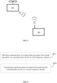
- FIG. 1 is a schematic block diagram showing an operating environment 100 according to exemplary embodiments of the present disclosure.
- the exemplary operating environment 100 includes a first communication device 102, a second communication device 104, and one or more monitoring detectors 105.
- the first communication device 102 can be a communication device arranged on or carried by a mobile object, or can be the mobile object itself.
- the first communication device 102 includes a first communication circuit 1022 and a second communication circuit 1024.
- the first communication circuit 1022 and the second communication circuit 1024 may support same or different wireless communication standards/protocols.
- one of the first communication circuit 1022 and the second communication circuit 1024 may implement a standard public communication protocol (e.g., Wi-Fi IEEE 802.11 standard or WiMAX IEEE 802.16 standard), and the other one may implement a proprietary communication technology such as software defined radio (SDR) protocol.
- SDR software defined radio
- Any proper communication protocols may be supported by the communication circuits 1022 and 1024, such as SDR, Wi-Fi, Bluetooth, Zigbee, LTE, GPRS, GSM, CDMA, etc.
- Each of the first communication circuit 1022 and the second communication circuit 1024 can, for example, be a chip or part of the chip including an integrated circuit.
- the first communication circuit 1022 and the second communication circuit 1024 may be located in a same housing in the first communication device 102, or separately at different parts of the first communication device 102.
- the first communication device 102 further includes an internal data exchange mechanism/interface between the first communication circuit 1022 and the second communication circuit 1024. That is, the first communication circuit 1022 and the second communication circuit 1024 are connected to each other directly or indirectly such that a monitoring data transmission scheme and/or commands received from the one or more monitoring detector 105 can be communicated between the first communication circuit 1022 and the second communication circuit 1024.
- connection interface between the first communication circuit 1022 and the second communication circuit 1024 can be any interface that is suitable for coupling two circuits.
- the connection interface can be a Universal Serial Bus (USB) interface, a High-Definition Multimedia Interface (HDMI), or a wireless link, such as a Wi-Fi link, a Bluetooth link, or a near-field communication link.
- USB Universal Serial Bus
- HDMI High-Definition Multimedia Interface
- wireless link such as a Wi-Fi link, a Bluetooth link, or a near-field communication link.
- the first communication device 102 is configured to, when one of the first communication circuit 1022 and the second communication circuit 1024 is performing working data communication, instruct the other one of the first communication circuit 1022 and the second communication circuit 1024 to transmit monitoring data in a channel not used by the working data communication.
- the first communication circuit 1022 is considered as the one performing the working data communication through a working frequency channel 106
- the second communication circuit 1024 is considered as the one transmitting the monitoring data through a stand-by frequency channel 108.
- the first communication device 102 can achieve transmitting the monitoring data in the stand-by frequency channel 108 (e.g., by the second communication circuit 1024) substantially concurrently with effecting working data communication with the second communication device 104 at the working frequency channel 106 (e.g., by the first communication circuit 1022).
- the first communication device 102 may transmit monitoring data at the stand-by frequency channel 108 during, shortly before (e.g., within about 1 millisecond before), or shortly after (e.g., within about 1 millisecond after) the working data communication with the second communication device 104 at the working frequency channel 106.
- the first communication circuit 1022 is configured to effect communication of the working data with the second communication device 104 at the working frequency channel 106, i.e., transmitting and/or receiving working data to and/or from the second communication device 104 through the working frequency channel 106.
- the working data can include, for example, status information, sensor information, and/or controlling information related to the first communication device 102 and/or the second communication device 104.
- the first communication device 102 can, through the first communication circuit 1022, transmit image data captured by an onboard camera and/or power level detected by an onboard sensor to the second communication device 104 at the working frequency channel 106.
- the first communication device 102 can, through the first communication circuit 1022, receive movement adjustment signal from the second communication device 104 at the working frequency channel 106, such that the first communication device 102 can change movement direction/speed/altitude based on the received adjustment signal.
- the second communication device 104 (e.g., a remote control of the mobile object) is exclusively paired with the first communication device 102 (e.g., the mobile object or carried by the mobile object) before the first communication device 102 starts normal operation (e.g., the mobile object operates/functions in accordance with control instructions from the remote control), such that the working data is communicated between the two devices for regular operations.
- the monitoring data is communicated with one or more monitoring detectors 105, after the first communication device 102 starts the normal operation with the second communication device 104.
- a monitoring detector 105 may receive monitoring data reported by multiple first communication devices 102 or other similar mobile objects having communication capabilities within a signal reception coverage range of the monitoring detector 105.
- the second communication circuit 1024 may transmit monitoring data at the stand-by frequency channel 108 (i.e., a frequency channel that is different from the working frequency channel 106), such that the monitoring data can be received by one of the one or more monitoring detectors 105 within a range of the second communication circuit 1024.
- the monitoring data can include, for example, data about a location of the first communication device 102 and/or a location of the second communication device 104.
- the first communication circuit 1022 may further transmit the monitoring data along with the working data at the working frequency channel 106 such that the monitoring data can be received by one of the one or more monitoring detectors 105 within the range of the first communication circuit 1022.
- the monitoring data is transmitted cyclically with fixed time intervals or variable time intervals. In some embodiments, the monitoring data is transmitted in response to a probe request generated by the one or more detectors 105.
- the monitoring data is not encrypted. In some other embodiments, the monitoring is encrypted using a key known to the one or more monitoring detectors 105.
- the monitoring data may be transmitted by hopping over any number of frequency channels. Such frequency-hopping mechanism can provide resistance against interference.
- all frequency channels 106 utilized by the first communication circuit 1022 are different from all frequency channels 108 utilized by the second communication circuit 1024.
- the first communication circuit 1022 can utilize first frequency channel(s) in a first frequency band
- the second communication circuit 1024 can operate at second frequency channel(s) in a second frequency band which is different from the first frequency band.
- the first communication device 102 can employ a monitoring data transmission scheme that assigns one or both of the first communication circuit 1022 and the second communication circuit 1024 to transmit the monitoring data at their respective operation frequency channels.
- the monitoring data transmission scheme may further include any applicable configuration for transmitting the monitoring data using the corresponding communication circuit, such as type(s) of contents to be included in the monitoring data, modulation method of the monitoring data, encoding scheme of the monitoring data, time or frequency for transmitting the monitoring data, and/or frequency channel for transmitting the monitoring data.
- first communication circuit 1022 and the second communication 1024 are both assigned to transmit the monitoring data, some or all of the configurations for transmitting the monitoring data by the first communication circuit 1022 may be different from the configurations for transmitting the monitoring data by the second communication circuit 1024.
- the monitoring data transmission scheme may assign the first communication circuit 1022 to transmit the monitoring data.
- the monitoring data is inserted into one or more data transmission units that include at least a portion of the working data.
- a data transmission unit may refer to a data unit having a specific data structure (e.g., defined sequence of bits, content fields, length, etc.) for being transmitted in compliance with a corresponding communication protocol.
- a data transmission unit may include one or more data transmission frames, one or more subframes, or any other types of data structures.
- the monitoring data is transmitted differently than the portion of the working data in the one or more transmission units in at least one of the working frequency band, modulation schemes, data formats and communication protocols.
- the portion of the working data may be deciphered by the second communication device 104 but not by the one or more monitoring detectors 105.
- the monitoring data is transmitted using a downlink and/or an uplink between the first communication device 1022 and the second communication device 1024.
- the first communication circuit 1022 may allocate a frame or a subframe in a data transmission unit for placing the monitoring data, and schedule specific time slots for transmitting the monitoring data.
- the monitoring data can be transmitted at time intervals T.
- the time interval T can be divided into two time slots: T1 and T2.
- Time slot T1 is designated for transmitting the monitoring data and time slot T2 is designated for transmitting the working data.
- Time slot T1 corresponds to a length of the monitoring data. That is, if the monitoring data has shorter length, less time is required to be assigned for transmitting the monitoring data.
- reducing the time interval T and/or shortening the time slot T1 by the first communication circuit 1022 can lower the impact of transmission of the monitoring data posed on transmission of the working data between the first communication device 102 and the second communication device 104.
- the monitoring data may be generated in the form of a datagram.
- the datagram can be transmitted using a data transmission unit.
- the data transmission unit may include a data transmission frame such as a management frame, a subframe, or a plurality of subframes or frames.
- the datagram may include a plurality of sub-datagrams such that the data transmission unit includes one or more of the sub-datagrams.
- each sub-datagram includes at least an index for the one or more monitoring detectors 105 to reconstruct the datagram.
- the data transmission unit may have a fixed length or a variable length.
- the management frame is transmitted using a Wi-Fi communication channel (e.g., by the second communication circuit 1024 or the first communication circuit 1022) under 802.11 standards.
- the management frame is a broadcasting frame.
- the broadcasting frame includes a beacon frame or a probe request frame.
- the management frame is a probe response frame and is transmitted in response to a probe request generated by the monitoring detector 105.
- the datagram is transmitted using software-defined radio (SDR) techniques.
- SDR software-defined radio
- information about the time slot or the one or more frequency channels are specified by the SDR techniques and may be known to one or more monitoring detectors 105.
- the datagram may be transmitted in the time division duplex (TDD) mode or frequency division duplex (FDD) mode.
- TDD time division duplex
- FDD frequency division duplex
- a sequence of the monitoring subframes are transmitted using frequency hopping on multiple frequencies and a frequency hopping pattern is known to the one or more monitoring detectors 105.
- the frequency hopping pattern is uniquely associated with an identity of the mobile object. Frequency hopping may occur at slot level or subframe level. For example, two monitoring subframes may be transmitted at different frequency channels.
- a monitoring detector 105 can pick up the monitoring data transmitted from the first communication device 102 when the first communication device 102 is within a range of the monitoring detector 105.
- the monitoring detector 105 can receive monitoring data sent in different communication modes and/or different communication standards/protocols.
- the one or more monitoring detectors 105 can operate at the stand-by frequency channel 108 to receive the monitoring data. In some embodiments, the one or more monitoring detectors 105 can further operate at the working frequency channel 106 to receive the monitoring data.
- the monitoring detector 105 may be configured to scan one or more frequency channels to detect the monitoring data. In some embodiments, the monitoring detector 105 may be configured to obtain subsequent monitoring data when first monitoring data is detected at a specific frequency channel.
- the first monitoring data may include information related to the transmission of the monitoring data such as allocation or scheduling of the monitoring data.
- the monitoring detector 105 may be configured to determine which frequency channel(s) to continue to listen or determine the scheduling of obtaining subsequent monitoring data according to such information.
- the monitoring detector 105 may continue to listen on the same frequency channel (e.g., when the monitoring data is transmitted based on Wi-Fi communication protocol) for receiving subsequent monitoring data.
- the monitoring detector 105 may continue to scan multiple predetermined frequency channels to obtain a sequence of monitoring data transmitted using frequency hopping scheme (e.g., based on a software defined radio protocol).
- the monitoring detector 105 may not be in direct communication with the second communication device 104. In some embodiments, the monitoring detector 105 can further transmit command data to the first communication device 102. In some embodiments, a plurality of the monitoring detectors 105 can be organized into zones to individually or collectively detect and monitor the first communication device 102 in certain areas/spaces. The monitoring detector 105 may be deployed in any designated monitored region or space, such as an airport, a government property, a factory, a private residence, etc. In some embodiments, the monitoring detector 105 may be a communication device integrated in another mobile object. In some embodiments, the monitoring detector 105 may be a mobile device such as a smartphone, a tablet, a laptop computer, etc.
- the one or more monitoring detectors 105 can be connected to a monitoring server 112.
- the monitoring server 112 can, in accordance with the monitoring data received from the one or more monitoring detectors 105 and/or the command data sent by the one or more monitoring detectors 105, monitor and regulate activities related to the first communication device 102 and/or the second communication device 104, such as: obtaining a location of the first communication device 102 and/or the second communication device 104, assessing a risk level related to the first communication device 102 and/or the second communication device 104, and sending controlling commands to the first communication device 102 and/or the second communication device 104 (e.g., according to regulation rules).
- certain functionalities of the monitoring server 112 described herein may also be implemented by the monitoring detector 105.
- the monitoring server 112 can receive the monitoring data collected by the one or more monitoring detectors 105, decrypt the monitoring data if necessary, and analyze the monitoring data (e.g., parsing based on certain demodulation/decoding scheme) to obtain information related to the mobile object.
- the monitoring server 112 may further access a database that stores regulatory rules and identification of registered mobile objects, and according to information from the database, verify an identity corresponding to the first communication device 102, determine whether a status of the first communication device 102 indicated by the monitoring data conforms with the regulatory rules, and generate a warning message if irregular activities are spotted.
- the monitoring server 112 may further generate commands for controlling the first communication device 102 or an entity related to the first communication device 102.
- the monitoring server 112 may send the commands to the monitoring detector 105 such that the commands are transmitted by the monitoring detector 105 and received by the first communication device 102.
- the command may adjust movement of a mobile object related to the first communication device 102, present a warning message on the second communication device 104, or switch a communication frequency channel of the first communication device 102.
- FIG. 2 is a schematic block diagram of a communication device 200 according to exemplary embodiments of the present disclosure.
- the communication device 200 includes at least one processor 204, at least one memory 202, and at least one transceiver 206.
- the at least one processor 204, the at least one memory 202, and the at least one transceiver 206 can be separate devices, or any two or more of them can be integrated in one device.
- the at least one memory 202 can include a non-transitory computer-readable storage medium, such as a random-access memory (RAM), a read only memory, a flash memory, a volatile memory, a hard disk storage, or an optical medium.
- the at least one memory 202 coupled to the at least one processor 204 may be configured to store instructions and/or data.
- the at least one memory 202 may be configured to store information related to communication standards supported by the communication device 200, computer executable instructions for implementing data communication process, or the like.
- the at least one processor 204 can include any suitable hardware processor, such as a microprocessor, a micro-controller, a central processing unit (CPU), a network processor (NP), a digital signal processor (DSP), an application specific integrated circuit (ASIC), a field-programmable gate array (FPGA), or another programmable logic device, discrete gate or transistor logic device, discrete hardware component.
- the at least one memory 202 stores computer program codes that, when executed by the at least one processor 204, control the at least one processor 204 and/or the at least one transceiver 206 to perform a communication method consistent with the disclosure, such as one of the exemplary communication methods described below.
- the computer program codes also control the at least one processor 204 to perform some or all of the functions that can be performed by the first communication device 102, the second communication device 104, the monitoring detector 105, or the monitoring server 112 as described above, each of which can be an example of the communication device 200.
- the at least one transceiver 206 is controlled by the at least one processor 204 for transmitting data to and/or receiving data from another device.
- the at least one transceiver 206 may include any number of transmitters and/or receivers suitable for wired and/or wireless communication.
- the transceiver 206 may include one or more antennas for wireless communication at any supported frequency channel.
- the at least one transceiver 106 is configured to operate at the working frequency channel 106 for transmitting and receiving working data and/or monitoring data, and/or operate at the stand-by frequency channel 108 for transmitting and receiving monitoring data.
- the processor can be any type of processor
- the memory can be any type of memory
- the transceiver can be any type of transceiver. The disclosure is not limited thereto.
- the communication device 200 can implement the first communication circuit 1022 and/or the second communication circuit 1024 of the first communication device 102.
- the first communication circuit 1022 and the second communication circuit 1024 may each include a set of processor, memory, and wireless transceiver.
- the first communication circuit 1022 and the second communication circuit 1024 may share a same processor, memory, and/or wireless transceiver.
- the first communication device 102 may include additional processor, memory, connection interface, and/or other hardware components for coordinating collaborations between the first communication circuit 1022 and the second communication circuit 1024.
- the at least one processor 204 coupled to the at least one memory 202 and the at least one transceiver 206, may be configured to obtain channel information through channel estimation.
- the channel information may include, but is not limited to, e.g., the SNR, SNIR, BER, CQI, transmission latency, channel bandwidth, and/or the like.
- the channel information can be estimated using pilot data and/or received data based on different channel estimation schemes.
- the channel estimation scheme can be chosen according to the required performance, computational complexity, time-variation of the channel, and/or the like.
- FIG. 3 a schematic diagram showing a mobile object 302 and a remote control 304 according to an exemplary embodiment of the present disclosure.
- the mobile object 302 can be, for example, an unmanned aerial vehicle (UAV), a driverless car, a mobile robot, a driverless boat, a submarine, a spacecraft, a satellite, a mobile phone, a tablet, a laptop, a wearable device, a digital camera, or the like.
- the first communication device 102 may be the mobile object 302 or may be integrated in or carried by the mobile object 302.
- the remote control 304 may be a remote controller or a terminal device with an application (app) that can control the first communication device 102 and/or the mobile object 302.
- the terminal device can be, for example, a smartphone, a tablet, a game device, or the like.
- the second communication device 104 may be the remote control 304 or may be integrated in the remote control 304.
- the second communication device 104 may be a hosted payload carried by the mobile object 302 that operates independently but may share the power supply of the mobile object 302.
- the second communication device 104 may be provided in another mobile object, such as a UAV, a driverless car, a mobile robot, a driverless boat, a submarine, a spacecraft, a satellite, a mobile phone, a tablet, a laptop, a wearable device, a digital camera, or the like.
- the second communication device 104 may be integrated in the mobile object 302, and the first communication device 102 may be integrated in the remote control 304, the payload, or the other mobile object.
- the working data transmitted between the first communication device 102 and the second communication device 104 may include data collected by sensors onboard the mobile object 304 (such as image data, GPS data, movement data, power level), information related to a communication channel between the mobile object 302 and the remote control 304, and/or operation commands from the remote control 304 (such as adjusting moving path, adjusting posture/position, operation to payload, zooming in/out an onboard camera, powering on/off an onboard sensor).
- data collected by sensors onboard the mobile object 304 such as image data, GPS data, movement data, power level
- information related to a communication channel between the mobile object 302 and the remote control 304 such as adjusting moving path, adjusting posture/position, operation to payload, zooming in/out an onboard camera, powering on/off an onboard sensor.
- the monitoring data transmitted from the first communication device 102 can include dynamic data (e.g., real-time data) related to the mobile object 302 and/or information indicating a physical state of the mobile object 302, such as a location of the mobile object 302 (e.g., detected by onboard GPS sensor), a location of the remote control 304, a speed of the mobile object 302, an orientation of the mobile object 302, etc.
- the monitoring data may include a latitude, longitude, and/or altitude of the UAV, flight distance of the UAV (e.g., distance from the remote control 304), and flight time of the UAV.
- the monitoring data can include identification information related to the mobile object 302, such as an identifier of the mobile object 302, an identity of an owner of the mobile object 302, a type of the mobile object 302, an identifier of the remote control 304, etc.
- the monitoring data can include control data (e.g., a control signal from a monitoring detector to change moving course of the mobile object), sensor data (e.g., data collected by on board sensors of the mobile object), telemetry data (e.g., altitude and/or speed of the mobile object), or payload data (e.g., data related to a payload carried by the mobile object) of the mobile object 302.
- FIGs. 4-6 are flow charts depicting various embodiments of the disclosed monitoring method.
- the disclosed method may be implemented by the first communication device 102 in accordance with FIG. 1 and/or the communication device 200 in accordance with FIG. 2 described above.
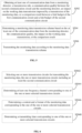
- FIG. 4 is a flow chart of a monitoring method according to an exemplary embodiment of the present disclosure.
- the method includes: effecting, by a first communication circuit of a communication device, communication of working data associated with normal operations of the communication device at a first frequency channel (S402); and transmitting monitoring data associated with monitoring the communication device at a second frequency channel (S404).
- the monitoring data can be transmitted substantially concurrently with effecting the communication of the working data
- the communication of the working data is implemented by a first communication circuit of the communication device; and the monitoring data is transmitted by a second communication circuit of the communication device.
- the first frequency channel e.g., the working frequency channel 106
- the second frequency channel e.g., the stand-by frequency channel 108
- the second communication circuit may transmit the monitoring data at multiple second frequency channels that are different from the first frequency channel.
- the first frequency band and/or the second frequency band are within the unlicensed spectrum, such as 2.4GHz-band and/or 5.8GHz-band.
- the working data associated with normal operations of the communication device is transmitted between the communication device and a linked device.
- the linked device refers to a device that is wirelessly connected to the first communication circuit at the first frequency channel.
- the communication device can be the first communication device 102 shown in FIG. 1 and the linked device can be the second communication device 104 shown in FIG. 1 .
- the working data associated with normal operations of the communication device may include sensor data and/or control data of at least one of the communication device, an object that integrates the communication device, an object that is connected to the communication device, the linked device, an object that integrates the linked device, or an object that is connected to the linked device.
- the monitoring data associated with monitoring the communication device is broadcasted at the second frequency channel such that one or more detectors within a range of the second communication circuit can receive the monitoring data.
- the monitoring data associated with monitoring the communication device may include at least a location of the communication device and/or a location of the linked device.
- the communication device can be the first communication device 102 shown in FIG. 1 and the one or more detectors can be the one or more monitoring detectors 105 shown in FIG. 1 .
- the one or more detectors may communicate with the monitoring server 112 to implement any proper monitoring and/or regulations on the communication device.
- FIG. 5 is a flow chart of a monitoring method according to another exemplary embodiment of the present disclosure.
- the communication device can obtain at least one of communication data from a monitoring detector, a transmission rule, a communication quality between the second communication circuit and the monitoring detector, an impact on working data transmission imposed by a transmission of the monitoring data, or a comparison result between a link budget of the first communication circuit and a link budget of the second communication circuit (S502).
- a monitoring data transmission scheme can be determined based on the at least one of the communication data from the monitoring detector, the transmission rule, the communication quality, the impact on the working data transmission, or the comparison result (S504).
- the communication device can transmit the monitoring data according to the monitoring data transmission scheme (S506).
- the communication device may receive communication data from a monitoring detector.
- the communication data may include at least one of a request for information related to the mobile object, a request for changing operation channel of the communication device, a control command related to the mobile object, or data related to the monitoring detector.
- the communication data may indicate a frequency channel or a frequency band that can be used by the communication device for transmitting the monitoring data.
- the communication data may further indicate a content to be included in the monitoring data, a format of the monitoring data, and/or a transmitting time of the monitoring data.
- the communication device can adjust the monitoring data transmission scheme based on requirements specified in the communication data from the monitoring detector (e.g., after verifying the source of the communication data).
- the communication device may gather the requested information and transmit the information to the monitoring detector by the second communication circuit.
- the second communication circuit may transmit the requested information as updated monitoring data to the monitoring detector.
- the data related to the monitoring detector may facilitate the communication device to determine whether an interference exists near the monitoring detector and adjust the monitoring data transmission scheme based on such data.
- the control command related to the mobile object may be processed by the communication device and implemented on the mobile object, such as reducing a speed of the mobile object, making the mobile object to fly/hover at a specific altitude, landing the mobile object at certain spot, etc.
- the transmission rule may be preconfigured and stored in the first communication device 102.
- the transmission rule may indicate at least part of the monitoring data transmission scheme based on a type and/or a priority level of the monitoring data being transmitted.
- the transmission rule may specify different transmission schemes for identification type monitoring data (e.g., model number, registration ID) and sensing type monitoring data (e.g., data collected by one or more sensors). Their respective transmission schemes may differ in transmission channel, transmission format, and/or transmission frequency. For example, monitoring data with a higher priority level is transmitted more frequently than monitoring data with a lower priority.
- the transmission rule may indicate at least part of the monitoring data transmission scheme based on laws and regulations. For example, laws and regulations in certain geographical location or jurisdiction area may require more frequent update of monitoring data than others.
- the communication device can obtain geographical coordinates of current location and determine at least part of the monitoring data transmission scheme based on prestored regulatory requirements of an area covering the current location.
- the transmission rule may also specify the monitoring data transmission scheme based on different surrounding environments (e.g., detected weather condition, channel condition, etc.).
- the communication device and/or the monitoring detector may evaluate a communication quality between the second communication circuit and the monitoring detector.
- One or more indicators of the communication quality can be obtained, such as noise, interference, signal-to-noise ratio, error rate, fading rate, throughput, latency, bandwidth, etc.
- the communication device may determine that the monitoring data transmission scheme includes assigning the second communication circuit to continue transmitting the monitoring data at the second frequency channel.
- the communication device may adjust the monitoring data transmission scheme by, for example, assigning the second communication circuit to transmit the monitoring data at the third frequency channel different from the second frequency channel, and/or, assigning both the first communication circuit and the second communication circuit to transmit the monitoring data.
- the communication device may determine an impact on working data transmission imposed by a transmission of the monitoring data. That is, when determining whether to transmit the monitoring data by the first communication circuit, the impact on the working data transmission is considered.
- the first communication circuit transmits the monitoring data along with the working data, and the impact on the working data transmission may include increasing the load on the first frequency channel and reducing the throughput of the working data transmission.
- the impact is below certain impact threshold, normal working data transmission is not affected, and the communication device may determine that the first communication circuit has the capacity to transmit the monitoring data.
- the communication device may determine that the first communication circuit has the capacity to transmit the monitoring data.
- the communication device may obtain a comparison result between a link budget of the first communication circuit and a link budget of the second communication circuit.
- comparison result may be predetermined based on the communication protocols implemented by the two communication circuits and/or hardware components (e.g., antenna type) of the communication circuits.
- a link budget may reflect all gains and losses from a transmitter to a receiver, and may reflect, e.g., an effective signal transmission distance between the transmitter and the receiver. That is, the first or second communication circuit needs to transmit signals at certain transmission power in order for the monitoring detector to effectively receive the transmitted signals.
- the monitoring data can be received by monitoring detectors in a wider range, and a monitoring/transmission distance of the communication circuit is greater.
- the first communication circuit may implement 802.11 standard Wi-Fi communication at 2.4GHz-band, which may have an outdoor monitoring distance of about 1 kilometers; and the second communication circuit may implement SDR techniques at 5.8GHz-band, which may have an outdoor monitoring distance of about 5 kilometers.
- a communication circuit having a higher link budget e.g., a longer monitoring distance is selected for transmitting the monitoring data.
- the monitoring data can be transmitted to monitoring detectors located in a wider distance range. Further, by transmitting the monitoring data from both communication circuits at two or more channels, the monitoring data can be received by more monitoring detectors.
- the working data communication can be implemented by the first communication circuit based on the 802.11 standard Wi-Fi communication at a first frequency channel, and the monitoring data can be transmitted by the second communication circuit based on SDR techniques at a second frequency channel. If the first communication circuit further transmits the monitoring data at the first frequency channel, practicality and effectiveness of monitoring the communication device can be improved because the monitoring data is transmitted by one more circuit at more channels.
- the first communication circuit does not transmit the monitoring data
- the second communication circuit has a higher link budget
- effectiveness of monitoring the communication device can still be improved, and the monitoring data communication will not cause interference with the working data communication and will not occupy resources for the working data communication.
- regular operations of the mobile object can be enhanced.
- the first communication circuit transmits the monitoring data at a rate lower than a designated rate
- the second communication circuit has a higher link budget
- effectiveness of monitoring the communication device can be improved, and the interference by the monitoring data communication with the working data communication can be reduced and more resources can be allocated to the communication of the working data.
- the regular operations of the mobile object can be enhanced
- a combination of two or more of the factors described above are evaluated to determine the monitoring data transmission scheme. For example, weights may be assigned to these factors and an overall evaluation may be obtained accordingly.
- FIG. 6 is a flow chart of a process for determining a monitoring data transmission scheme according to an exemplary embodiment of the present disclosure.
- the monitoring data transmission scheme may include any proper information related to transmitting the monitoring data.
- determining the monitoring data transmission scheme e.g., S504 in FIG. 5
- the first communication circuit may be selected to transmit the monitoring data in one or more of the following situations: an interference exists at the second frequency channel, an impact on the working data transmission imposed by a transmission of the monitoring data is below an impact threshold, the first communication circuit has a higher link budget than the second communication circuit (e.g., a wider effective range for signal transmission), and a controlling command from the monitoring detector is received that requires the monitoring data to be sent at a frequency channel or a format supported by the first communication circuit.
- the first communication circuit when a communication quality between the second communication circuit and the monitoring detector is above a quality threshold (e.g., no interference exists at the second frequency channel or the interference is low), and/or an impact on the working data transmission imposed by the transmission of the monitoring data is above the impact threshold (e.g., transmitting the monitoring data would occupy valuable resources for transmitting working data), the first communication circuit is not selected for transmitting the monitoring data.
- a quality threshold e.g., no interference exists at the second frequency channel or the interference is low
- an impact threshold e.g., transmitting the monitoring data would occupy valuable resources for transmitting working data
- determining the monitoring data transmission scheme may include determining at least one frequency channel corresponding to one of the one or more selected transmission circuits (S5044). For example, given that the working data is transmitted at the first frequency channel by the first communication circuit, the second frequency channel corresponding to the second communication circuit may be determined by avoiding channels that overlap the first frequency channel or by selecting a channel that is in a different frequency band than the first frequency channel. If the first communication circuit is also selected for transmitting the monitoring data, a frequency channel corresponding to the first communication circuit may be determined as the first frequency channel, which can be used to transmit both the working data and the monitoring data.
- determining the monitoring data transmission scheme may include determining a content and a format of the monitoring data corresponding to the one of the one or more selected transmission circuits (S5046).
- the format of the monitoring data such as encoding scheme and modulation method of the monitoring data, may be preconfigured based on the communication protocols supported by corresponding communication circuit.
- the content of the monitoring data may be determined based on a preconfigured default format, a data length allowed to be transmitted in current channel condition and communication capacity, and/or requirements sent by the monitoring detector.
- the contents and/or formats of the monitoring data transmitted by the two communication circuits may or may not be the same.
- determining the monitoring data transmission scheme may include determining a transmitting time corresponding one of the one or more selected transmission circuits (S5048). Being a communication circuit that does not transmit the working data, the second communication circuit may transmit the monitoring data at any proper fixed or variable time intervals, or in response to a probe request from the monitoring detector. The first communication circuit, on the other hand, if being selected, may require a coordinated schedule for transmitting the monitoring data and the working data.
- the communication device may determine a rate/frequency for the first communication circuit to transmit the monitoring data.
- the rate may be less than or equal to a designated rate.
- the designated rate is configured for the first communication circuit based on time slots assigned for transmitting the monitoring data and time slots assigned for transmitting the working data at each communication cycle of the first communication circuit when the second communication circuit is not available (e.g., a rate required by regulations).
- each communication cycle may include 40 time slots, among which 6 time slots may be assigned to transmit the monitoring data, and the remaining time slots may be assigned to transmit the working data.
- the designated rate may be 6/40.
- the communication device may determine to transmit the monitoring data by the first communication circuit at a target rate lower than the designated rate.
- the communication device may determine to transmit the monitoring data by the first communication circuit at the designated rate.
- the impact on the working data transmission imposed by transmission of the monitoring data may be determined based on the bandwidth at the first frequency channel and/or data volume of to-be-transmitted working data. For example, when the bandwidth is enough for transmitting the working data and the monitoring data, the impact may be determined as low or zero; and when the bandwidth is not enough or just enough for transmitting the working data, the impact may be determined as high.
- the communication device may further consider other factors to evaluate the impact, such as volume of the monitoring data and channel condition at the first frequency channel.
- the communication device may determine the target rate according to current load at the first frequency channel. For example, the target rate for transmitting the monitoring data may be inversely correlated to the current load such that transmitting the monitoring data is affordable without affecting the working data transmission.
- the present disclosure provides a monitoring method and device applicable for a communication device containing two communication circuits. Comparing to using a single communication circuit for transmitting both the working data and monitoring data, when only the second communication circuit is transmitting the monitoring data or when the first communication circuit is transmitting the monitoring data at a rate lower than the designated rate, the load on the first frequency channel is reduced, the impact of monitoring data transmission imposed on working data transmission is reduced or even removed, and communication quality and performance of the mobile object can be improved. When both communication circuits are selected for transmitting the monitoring data, the monitoring data are transmitted at two different channels, such that improved accessibility and efficiency for monitoring the mobile object can be achieved. Further, the monitoring distance can be extended when the link budget of the second communication circuit is greater than that of the first communication circuit.
- the components in the figures associated with the device embodiments can be coupled in a manner different from that shown in the figures as needed. Some components may be omitted and additional components may be added.
Landscapes
- Engineering & Computer Science (AREA)
- Computer Networks & Wireless Communication (AREA)
- Signal Processing (AREA)
- Physics & Mathematics (AREA)
- General Physics & Mathematics (AREA)
- Aviation & Aerospace Engineering (AREA)
- Quality & Reliability (AREA)
- Radar, Positioning & Navigation (AREA)
- Remote Sensing (AREA)
- Automation & Control Theory (AREA)
- Astronomy & Astrophysics (AREA)
- Mobile Radio Communication Systems (AREA)
Claims (12)
- Dispositif (102) agencé au niveau d'un objet mobile ou d'une commande à distance de l'objet mobile, le dispositif comprenant :un premier circuit de communication (1022) configuré de manière à mettre en oeuvre une communication de données de travail associées à des opérations du dispositif sur un premier canal de fréquence (106) ;dans lequel l'étape de mise en oeuvre de la communication des données de travail comprend l'étape consistant à transmettre et à recevoir les données de travail, à destination et en provenance de la commande à distance (104) ;un second circuit de communication (1024) configuré de manière à transmettre des données de surveillance de l'objet mobile, sur un second canal de fréquence (108), à un détecteur de surveillance (105), dans lequel les données de surveillance de l'objet mobile comprennent au moins l'un des éléments parmi un emplacement de l'objet mobile, une vitesse de l'objet mobile, une orientation de l'objet mobile ou un emplacement de la commande à distance de l'objet mobile ;un processeur configuré de manière à déterminer s'il convient de transmettre les données de surveillance par le biais du premier circuit de communication, sur la base d'au moins l'un des éléments parmi :une qualité de communication entre le second circuit de communication et le détecteur de surveillance ;un impact sur une transmission de données de travail imposée par une transmission des données de surveillance ; etun résultat de comparaison entre un budget de liaison du premier circuit de communication etun budget de liaison du second circuit de communication ; etdans lequel le premier canal de fréquence et le second canal de fréquence appartiennent à des bandes de fréquence différentes ; oudans lequel le premier canal de fréquence et le second canal de fréquence appartiennent à la même bande de fréquence, et le premier canal de fréquence ne chevauche pas le second canal de fréquence.
- Dispositif selon la revendication 1, dans lequel le processeur est en outre configuré de manière à :lorsque la qualité de communication est supérieure à un seuil de qualité, déterminer qu'il convient de ne pas transmettre les données de surveillance par le biais du premier circuit de communication ; etlorsque la qualité de communication est inférieure au seuil de qualité, déterminer qu'il convient de transmettre les données de surveillance par le biais du premier circuit de communication.
- Dispositif selon la revendication 1, dans lequel : la qualité de communication est déterminée sur la base d'au moins l'un des éléments parmi une largeur de bande, un rendement, une latence ou un taux d'erreur sur le second canal de fréquence.
- Dispositif selon la revendication 1, dans lequel le processeur est en outre configuré de manière à :lorsque l'impact est inférieur à un premier seuil d'impact, déterminer qu'il convient de transmettre les données de surveillance par le biais du premier circuit de communication ; etlorsque l'impact est supérieur au premier seuil d'impact, déterminer qu'il convient de ne pas transmettre les données de surveillance par le biais du premier circuit de communication.
- Dispositif selon la revendication 4, dans lequel le processeur est en outre configuré de manière à :lorsque l'impact est inférieur à un second seuil d'impact, déterminer qu'il convient de transmettre les données de surveillance, par le biais du premier circuit de communication, à un débit désigné ; etlorsque l'impact est supérieur au second seuil d'impact et est inférieur au premier seuil d'impact, déterminer qu'il convient de transmettre les données de surveillance, par le biais du premier circuit de communication, à un débit cible inférieur au débit désigné ;dans lequel le débit désigné est prédéfini sur la base de tranches de temps affectées pour transmettre les données de surveillance et de tranches de temps affectées pour transmettre les données de travail, à chaque cycle de communication du premier circuit de communication, lorsque le second circuit de communication n'est pas disponible.
- Dispositif selon la revendication 1, dans lequel :
l'impact sur la transmission de données de travail imposée par la transmission des données de surveillance est déterminé selon une performance réseau sur le premier canal de fréquence, la performance réseau comprenant au moins l'un des éléments parmi une largeur de bande, un rendement, une latence ou un taux d'erreur. - Dispositif selon la revendication 1, dans lequel le processeur est en outre configuré de manière à :déterminer qu'il convient de transmettre les données de surveillance, par le biais du premier circuit de communication, lorsque le budget de liaison du premier circuit de communication est supérieur à celui du second circuit de communication ; etdéterminer qu'il convient de ne pas transmettre les données de surveillance, par le biais du premier circuit de communication, lorsque le budget de liaison du premier circuit de communication est inférieur ou égal à celui du second circuit de communication.
- Dispositif selon la revendication 1, dans lequel le processeur est en outre configuré de manière à :
déterminer un schéma de transmission de données de surveillance sur la base d'au moins l'un des éléments parmi des données de communication provenant du détecteur de surveillance, la qualité de communication, l'impact sur la transmission de données de travail ou le résultat de comparaison, en mettant en oeuvre au moins l'une des étapes ci-dessous consistant à :sélectionner un ou plusieurs circuits de transmission pour transmettre les données de surveillance, ledit un ou lesdits plusieurs circuits de transmission incluant au moins le second circuit de communication ;déterminer au moins un canal de fréquence correspondant à l'un dudit un ou desdits plusieurs circuits de transmission sélectionnés ;déterminer un contenu et un format des données de surveillance correspondant audit un circuit dudit un ou desdits plusieurs circuits de transmission sélectionnés ; oudéterminer un instant de transmission correspondant à l'un dudit un ou desdits plusieurs circuits de transmission sélectionnés ; ettransmettre les données de surveillance selon le schéma de transmission de données de surveillance. - Dispositif selon la revendication 1, dans lequel :
les données de surveillance sont transmises sensiblement simultanément à l'étape de mise en oeuvre de la communication des données de travail. - Dispositif selon l'une quelconque des revendications 1 à 9, dans lequel le premier circuit de communication est configuré de manière à fonctionner selon un premier protocole de communication, et le second circuit de communication est configuré de manière à fonctionner selon un second protocole de communication.
- Dispositif selon l'une quelconque des revendications 1 à 9, dans lequel le premier protocole de communication est un protocole normalisé et le second protocole de communication est un protocole propriétaire.
- Procédé de surveillance mis en oeuvre par un dispositif agencé au niveau d'un objet mobile ou d'une commande à distance de l'objet mobile, le dispositif comprenant un premier circuit de communication et un second circuit de communication, le procédé de surveillance comprenant les étapes ci-dessous consistant à :mettre en oeuvre (S402), par le biais du premier circuit de communication, une communication de données de travail associées à des opérations d'un dispositif de communication sur un premier canal de fréquence ;dans lequel l'étape de mise en oeuvre de la communication des données de travail comprend l'étape consistant à transmettre et à recevoir les données de travail, à destination et en provenance de la commande à distance ;transmettre (S404), par le biais du second circuit de communication, des données de surveillance de l'objet mobile, sur un second canal de fréquence, à un détecteur de surveillance, dans lequel les données de surveillance de l'objet mobile comprennent au moins l'un des éléments parmi un emplacement de l'objet mobile, une vitesse de l'objet mobile, une orientation de l'objet mobile ou un emplacement de la commande à distance de l'objet mobile ;déterminer s'il convient de transmettre les données de surveillance, par le biais du premier circuit de communication, sur la base d'au moins l'un des éléments parmi :une qualité de communication entre le second circuit de communication et le détecteur de surveillance ;un impact sur une transmission de données de travail imposée par une transmission des données de surveillance ; etun résultat de comparaison entre un budget de liaison du premier circuit de communication etun budget de liaison du second circuit de communication ; etdans lequel le premier canal de fréquence et le second canal de fréquence appartiennent à des bandes de fréquence différentes ; oudans lequel le premier canal de fréquence et le second canal de fréquence appartiennent à une même bande de fréquence, et le premier canal de fréquence ne chevauche pas le second canal de fréquence.
Priority Applications (1)
| Application Number | Priority Date | Filing Date | Title |
|---|---|---|---|
| EP21178665.2A EP3897009B1 (fr) | 2018-02-22 | 2018-02-22 | Procédé et dispositif de surveillance |
Applications Claiming Priority (3)
| Application Number | Priority Date | Filing Date | Title |
|---|---|---|---|
| EP21178665.2A EP3897009B1 (fr) | 2018-02-22 | 2018-02-22 | Procédé et dispositif de surveillance |
| PCT/CN2018/076971 WO2019161531A1 (fr) | 2018-02-22 | 2018-02-22 | Procédé et dispositif de surveillance |
| EP18907038.6A EP3616022B1 (fr) | 2018-02-22 | 2018-02-22 | Procédé et dispositif de surveillance |
Related Parent Applications (2)
| Application Number | Title | Priority Date | Filing Date |
|---|---|---|---|
| EP18907038.6A Division EP3616022B1 (fr) | 2018-02-22 | 2018-02-22 | Procédé et dispositif de surveillance |
| EP18907038.6A Division-Into EP3616022B1 (fr) | 2018-02-22 | 2018-02-22 | Procédé et dispositif de surveillance |
Publications (2)
| Publication Number | Publication Date |
|---|---|
| EP3897009A1 EP3897009A1 (fr) | 2021-10-20 |
| EP3897009B1 true EP3897009B1 (fr) | 2023-05-31 |
Family
ID=67686609
Family Applications (2)
| Application Number | Title | Priority Date | Filing Date |
|---|---|---|---|
| EP21178665.2A Active EP3897009B1 (fr) | 2018-02-22 | 2018-02-22 | Procédé et dispositif de surveillance |
| EP18907038.6A Active EP3616022B1 (fr) | 2018-02-22 | 2018-02-22 | Procédé et dispositif de surveillance |
Family Applications After (1)
| Application Number | Title | Priority Date | Filing Date |
|---|---|---|---|
| EP18907038.6A Active EP3616022B1 (fr) | 2018-02-22 | 2018-02-22 | Procédé et dispositif de surveillance |
Country Status (4)
| Country | Link |
|---|---|
| US (2) | US12389253B2 (fr) |
| EP (2) | EP3897009B1 (fr) |
| CN (2) | CN111183403B (fr) |
| WO (1) | WO2019161531A1 (fr) |
Families Citing this family (6)
| Publication number | Priority date | Publication date | Assignee | Title |
|---|---|---|---|---|
| JP7271380B2 (ja) * | 2019-09-19 | 2023-05-11 | 株式会社東芝 | 無線通信装置および方法 |
| CN112136164B (zh) * | 2019-09-30 | 2022-07-29 | 深圳市大疆创新科技有限公司 | 支架结构及可移动平台 |
| CN112533160B (zh) * | 2020-11-30 | 2023-10-20 | 天宸星通(深圳)科技有限公司 | 一种监控卫星物联网终端运行状态的方法 |
| CN113810938B (zh) * | 2021-06-29 | 2022-09-27 | 荣耀终端有限公司 | 通道切换方法、电子设备及存储介质 |
| CN114025362B (zh) * | 2022-01-05 | 2022-04-01 | 华东交通大学 | 基于无线通信和分布式计算的铁路施工安全监测方法 |
| CN120932434A (zh) * | 2024-05-11 | 2025-11-11 | 北京字跳网络技术有限公司 | 用于设备通信的方法、装置、设备、存储介质和程序产品 |
Family Cites Families (28)
| Publication number | Priority date | Publication date | Assignee | Title |
|---|---|---|---|---|
| US9167272B2 (en) * | 2012-04-25 | 2015-10-20 | Omnivision Technologies, Inc. | Method, apparatus and system for exchanging video data in parallel |
| CN103490842B (zh) * | 2013-09-26 | 2016-09-28 | 深圳市大疆创新科技有限公司 | 数据传输系统及方法 |
| CN103543752B (zh) * | 2013-10-09 | 2017-03-15 | 深圳市大疆创新科技有限公司 | 一种遥控方法和遥控系统 |
| CN104661228B (zh) * | 2013-11-22 | 2018-11-06 | 韩国电子通信研究院 | 用于设置排他传送信道以避免干扰信号的设备和方法 |
| US9813914B2 (en) * | 2013-12-06 | 2017-11-07 | Qualcomm Incorporated | System and method for management of spectrum interference rights and secondary use permissions |
| US9646502B1 (en) * | 2015-02-27 | 2017-05-09 | Amazon Technologies, Inc. | Universal unmanned aerial vehicle identification system |
| EP3266009B1 (fr) * | 2015-03-02 | 2025-12-31 | Copeland Cold Chain LP | Systèmes et procédés pour surveiller des articles transportés |
| US9836047B2 (en) * | 2015-06-10 | 2017-12-05 | Kespry, Inc. | Aerial vehicle data communication system |
| KR20170028811A (ko) * | 2015-09-04 | 2017-03-14 | 유성훈 | 무인 비행체의 비행을 모니터링하는 방법, 사용자 단말, 서버 및 디텍팅 장치 |
| AU2016331221B2 (en) * | 2015-09-30 | 2020-02-27 | Alarm.Com Incorporated | Drone-augmented emergency response services |
| CN205103662U (zh) * | 2015-11-13 | 2016-03-23 | 南京衡创天伟无人机技术有限公司 | 一种无人机航拍系统 |
| CN105242686B (zh) * | 2015-11-13 | 2017-09-29 | 南京衡创天伟无人机技术有限公司 | 一种无人机航拍系统和航拍方法 |
| CN106873404A (zh) * | 2015-12-14 | 2017-06-20 | 天津益华微电子有限公司 | 一种无人机安全控制器 |
| CN106873618A (zh) * | 2015-12-14 | 2017-06-20 | 天津益华微电子有限公司 | 一种无人机监控系统 |
| CN105739520B (zh) * | 2016-01-29 | 2019-10-08 | 余江 | 一种无人飞行器识别系统及其识别方法 |
| EP3446186A4 (fr) | 2016-04-18 | 2019-12-11 | Rhombus Systems Group, Inc. | Système permettant de communiquer avec des véhicules aériens sans pilote utilisant deux bandes de fréquence |
| WO2017185316A1 (fr) * | 2016-04-29 | 2017-11-02 | 深圳市大疆创新科技有限公司 | Procédé et système de commande de vol de vue subjective pour véhicule aérien sans pilote et lunettes intelligentes |
| US9980267B2 (en) * | 2016-05-06 | 2018-05-22 | Bridgewest Finance Llc | Unmanned aerial vehicle (UAV) beam pointing and data rate optimization for high throughput broadband access |
| WO2017196213A1 (fr) * | 2016-05-11 | 2017-11-16 | Telefonaktiebolaget Lm Ericsson (Publ) | Commande à distance d'un véhicule aérien sans pilote |
| CN109479119B (zh) * | 2016-07-22 | 2021-03-05 | 深圳市大疆创新科技有限公司 | Uav交互视频广播的系统与方法 |
| JP7088016B2 (ja) * | 2016-09-02 | 2022-06-21 | ソニーグループ株式会社 | 回路、端末装置、基地局装置及び方法 |
| DE102016010690A1 (de) * | 2016-09-06 | 2018-03-08 | Daimler Ag | Fahrzeug mit Drohnenlandefunktionalität |
| WO2018048854A1 (fr) | 2016-09-09 | 2018-03-15 | Wal-Mart Stores, Inc. | Appareil et procédé d'optimisation de tâche de vol sans pilote |
| US20180176841A1 (en) * | 2016-12-20 | 2018-06-21 | Microsoft Technology Licensing, Llc | Switching between network media based on connection quality |
| FR3061028B1 (fr) * | 2016-12-27 | 2019-05-31 | Parrot Drones | Drone a diversite dynamique d'antennes |
| US10270717B2 (en) * | 2017-03-10 | 2019-04-23 | Avago Technologies International Sales Pte. Limited | Unified media access control (MAC) for multiple physical layer devices |
| US20190045454A1 (en) * | 2017-08-03 | 2019-02-07 | Autotalks Ltd. | Method and apparatus for coexistence of a v2x safety channel with other channels |
| GB2569789A (en) | 2017-12-21 | 2019-07-03 | Av8Or Ip Ltd | Autonomous unmanned aerial vehicle and method of control thereof |
-
2018
- 2018-02-22 EP EP21178665.2A patent/EP3897009B1/fr active Active
- 2018-02-22 WO PCT/CN2018/076971 patent/WO2019161531A1/fr not_active Ceased
- 2018-02-22 CN CN201880065005.9A patent/CN111183403B/zh active Active
- 2018-02-22 CN CN202410404804.1A patent/CN118316508A/zh active Pending
- 2018-02-22 EP EP18907038.6A patent/EP3616022B1/fr active Active
-
2020
- 2020-08-17 US US16/995,294 patent/US12389253B2/en active Active
-
2025
- 2025-07-17 US US19/272,805 patent/US20250350989A1/en active Pending
Also Published As
| Publication number | Publication date |
|---|---|
| EP3616022A1 (fr) | 2020-03-04 |
| EP3616022A4 (fr) | 2020-03-18 |
| CN111183403B (zh) | 2024-04-26 |
| US20250350989A1 (en) | 2025-11-13 |
| US20200382983A1 (en) | 2020-12-03 |
| EP3616022B1 (fr) | 2021-07-21 |
| US12389253B2 (en) | 2025-08-12 |
| EP3897009A1 (fr) | 2021-10-20 |
| WO2019161531A1 (fr) | 2019-08-29 |
| CN118316508A (zh) | 2024-07-09 |
| CN111183403A (zh) | 2020-05-19 |
Similar Documents
| Publication | Publication Date | Title |
|---|---|---|
| US20250350989A1 (en) | Monitoring method and device | |
| US11706593B2 (en) | Terminal device, method, and recording medium | |
| EP4013171B1 (fr) | Procédé destiné à un équipement utilisateur dans un système de communications sans fil | |
| US11171708B2 (en) | Device/UE-oriented beam recovery and maintenance mechanisms | |
| US9806794B2 (en) | Antenna system for a broadband access to airborne platforms | |
| US20220217497A1 (en) | Position signaling within a wireless communication system | |
| JP2021506192A (ja) | 無人航空機によるダウンリンク信号のアップリンク干渉に基づく監視 | |
| KR20220065806A (ko) | 사이드링크를 이용한 측위 방법 및 이를 위한 장치 | |
| KR20220050920A (ko) | 무선통신시스템에서 사이드링크 신호를 송수신하는 방법 | |
| KR20230008744A (ko) | 무선 통신 시스템에서 신호 전송 방법 및 장치 | |
| US20200404590A1 (en) | Interfering device identification | |
| CN120957242B (zh) | 一种通信方法及相关装置 | |
| CN113556189A (zh) | 无人机的天线调整方法和装置 | |
| WO2019032939A1 (fr) | Atténuation des interférences pour communications de véhicule aérien par partage d'informations de planification avec des stations de base voisines | |
| US20250253939A1 (en) | System and methods for regulatory-aware access to network resources over satellites | |
| JP7562693B2 (ja) | 同期されたモバイルデバイス間で通信する方法、記憶媒体及びモバイルデバイス | |
| US20230379983A1 (en) | Frequency Hopping Scheme For Improved Operation In Congested Environments | |
| WO2025081780A1 (fr) | Procédés, dispositifs et support de stockage lisible par ordinateur pour obtenir des services de détection | |
| WO2025065640A1 (fr) | Systèmes et procédés de gestion d'un équipement d'utilisateur en connexion avec une zone sans émission | |
| KR20250132449A (ko) | 무선 통신 시스템에서 신호를 송수신 하는 방법 및 이를 위한 장치 | |
| CN119767318A (zh) | 感知方法、装置和系统 | |
| CN120642354A (zh) | 在无线通信系统中网络发送消息的方法及其设备 |
Legal Events
| Date | Code | Title | Description |
|---|---|---|---|
| PUAI | Public reference made under article 153(3) epc to a published international application that has entered the european phase |
Free format text: ORIGINAL CODE: 0009012 |
|
| STAA | Information on the status of an ep patent application or granted ep patent |
Free format text: STATUS: THE APPLICATION HAS BEEN PUBLISHED |
|
| AC | Divisional application: reference to earlier application |
Ref document number: 3616022 Country of ref document: EP Kind code of ref document: P |
|
| AK | Designated contracting states |
Kind code of ref document: A1 Designated state(s): AL AT BE BG CH CY CZ DE DK EE ES FI FR GB GR HR HU IE IS IT LI LT LU LV MC MK MT NL NO PL PT RO RS SE SI SK SM TR |
|
| B565 | Issuance of search results under rule 164(2) epc |
Effective date: 20210906 |
|
| STAA | Information on the status of an ep patent application or granted ep patent |
Free format text: STATUS: REQUEST FOR EXAMINATION WAS MADE |
|
| 17P | Request for examination filed |
Effective date: 20220406 |
|
| RBV | Designated contracting states (corrected) |
Designated state(s): AL AT BE BG CH CY CZ DE DK EE ES FI FR GB GR HR HU IE IS IT LI LT LU LV MC MK MT NL NO PL PT RO RS SE SI SK SM TR |
|
| GRAP | Despatch of communication of intention to grant a patent |
Free format text: ORIGINAL CODE: EPIDOSNIGR1 |
|
| STAA | Information on the status of an ep patent application or granted ep patent |
Free format text: STATUS: GRANT OF PATENT IS INTENDED |
|
| RIC1 | Information provided on ipc code assigned before grant |
Ipc: H04W 72/04 20090101ALI20230119BHEP Ipc: H04B 7/185 20060101ALI20230119BHEP Ipc: G08C 17/02 20060101ALI20230119BHEP Ipc: G05D 1/10 20060101ALI20230119BHEP Ipc: H04W 4/44 20180101AFI20230119BHEP |
|
| INTG | Intention to grant announced |
Effective date: 20230214 |
|
| GRAS | Grant fee paid |
Free format text: ORIGINAL CODE: EPIDOSNIGR3 |
|
| GRAA | (expected) grant |
Free format text: ORIGINAL CODE: 0009210 |
|
| STAA | Information on the status of an ep patent application or granted ep patent |
Free format text: STATUS: THE PATENT HAS BEEN GRANTED |
|
| AC | Divisional application: reference to earlier application |
Ref document number: 3616022 Country of ref document: EP Kind code of ref document: P |
|
| AK | Designated contracting states |
Kind code of ref document: B1 Designated state(s): AL AT BE BG CH CY CZ DE DK EE ES FI FR GB GR HR HU IE IS IT LI LT LU LV MC MK MT NL NO PL PT RO RS SE SI SK SM TR |
|
| REG | Reference to a national code |
Ref country code: GB Ref legal event code: FG4D Ref country code: CH Ref legal event code: EP |
|
| REG | Reference to a national code |
Ref country code: DE Ref legal event code: R096 Ref document number: 602018050629 Country of ref document: DE |
|
| REG | Reference to a national code |
Ref country code: AT Ref legal event code: REF Ref document number: 1571740 Country of ref document: AT Kind code of ref document: T Effective date: 20230615 |
|
| REG | Reference to a national code |
Ref country code: IE Ref legal event code: FG4D |
|
| P01 | Opt-out of the competence of the unified patent court (upc) registered |
Effective date: 20230523 |
|
| REG | Reference to a national code |
Ref country code: LT Ref legal event code: MG9D |
|
| REG | Reference to a national code |
Ref country code: NL Ref legal event code: MP Effective date: 20230531 |
|
| REG | Reference to a national code |
Ref country code: AT Ref legal event code: MK05 Ref document number: 1571740 Country of ref document: AT Kind code of ref document: T Effective date: 20230531 |
|
| PG25 | Lapsed in a contracting state [announced via postgrant information from national office to epo] |
Ref country code: SE Free format text: LAPSE BECAUSE OF FAILURE TO SUBMIT A TRANSLATION OF THE DESCRIPTION OR TO PAY THE FEE WITHIN THE PRESCRIBED TIME-LIMIT Effective date: 20230531 Ref country code: NO Free format text: LAPSE BECAUSE OF FAILURE TO SUBMIT A TRANSLATION OF THE DESCRIPTION OR TO PAY THE FEE WITHIN THE PRESCRIBED TIME-LIMIT Effective date: 20230831 Ref country code: ES Free format text: LAPSE BECAUSE OF FAILURE TO SUBMIT A TRANSLATION OF THE DESCRIPTION OR TO PAY THE FEE WITHIN THE PRESCRIBED TIME-LIMIT Effective date: 20230531 Ref country code: AT Free format text: LAPSE BECAUSE OF FAILURE TO SUBMIT A TRANSLATION OF THE DESCRIPTION OR TO PAY THE FEE WITHIN THE PRESCRIBED TIME-LIMIT Effective date: 20230531 |
|
| PG25 | Lapsed in a contracting state [announced via postgrant information from national office to epo] |
Ref country code: RS Free format text: LAPSE BECAUSE OF FAILURE TO SUBMIT A TRANSLATION OF THE DESCRIPTION OR TO PAY THE FEE WITHIN THE PRESCRIBED TIME-LIMIT Effective date: 20230531 Ref country code: PL Free format text: LAPSE BECAUSE OF FAILURE TO SUBMIT A TRANSLATION OF THE DESCRIPTION OR TO PAY THE FEE WITHIN THE PRESCRIBED TIME-LIMIT Effective date: 20230531 Ref country code: NL Free format text: LAPSE BECAUSE OF FAILURE TO SUBMIT A TRANSLATION OF THE DESCRIPTION OR TO PAY THE FEE WITHIN THE PRESCRIBED TIME-LIMIT Effective date: 20230531 Ref country code: LV Free format text: LAPSE BECAUSE OF FAILURE TO SUBMIT A TRANSLATION OF THE DESCRIPTION OR TO PAY THE FEE WITHIN THE PRESCRIBED TIME-LIMIT Effective date: 20230531 Ref country code: LT Free format text: LAPSE BECAUSE OF FAILURE TO SUBMIT A TRANSLATION OF THE DESCRIPTION OR TO PAY THE FEE WITHIN THE PRESCRIBED TIME-LIMIT Effective date: 20230531 Ref country code: IS Free format text: LAPSE BECAUSE OF FAILURE TO SUBMIT A TRANSLATION OF THE DESCRIPTION OR TO PAY THE FEE WITHIN THE PRESCRIBED TIME-LIMIT Effective date: 20230930 Ref country code: HR Free format text: LAPSE BECAUSE OF FAILURE TO SUBMIT A TRANSLATION OF THE DESCRIPTION OR TO PAY THE FEE WITHIN THE PRESCRIBED TIME-LIMIT Effective date: 20230531 Ref country code: GR Free format text: LAPSE BECAUSE OF FAILURE TO SUBMIT A TRANSLATION OF THE DESCRIPTION OR TO PAY THE FEE WITHIN THE PRESCRIBED TIME-LIMIT Effective date: 20230901 |
|
| PG25 | Lapsed in a contracting state [announced via postgrant information from national office to epo] |
Ref country code: FI Free format text: LAPSE BECAUSE OF FAILURE TO SUBMIT A TRANSLATION OF THE DESCRIPTION OR TO PAY THE FEE WITHIN THE PRESCRIBED TIME-LIMIT Effective date: 20230531 |
|
| PG25 | Lapsed in a contracting state [announced via postgrant information from national office to epo] |
Ref country code: SK Free format text: LAPSE BECAUSE OF FAILURE TO SUBMIT A TRANSLATION OF THE DESCRIPTION OR TO PAY THE FEE WITHIN THE PRESCRIBED TIME-LIMIT Effective date: 20230531 |
|
| PG25 | Lapsed in a contracting state [announced via postgrant information from national office to epo] |
Ref country code: SM Free format text: LAPSE BECAUSE OF FAILURE TO SUBMIT A TRANSLATION OF THE DESCRIPTION OR TO PAY THE FEE WITHIN THE PRESCRIBED TIME-LIMIT Effective date: 20230531 Ref country code: SK Free format text: LAPSE BECAUSE OF FAILURE TO SUBMIT A TRANSLATION OF THE DESCRIPTION OR TO PAY THE FEE WITHIN THE PRESCRIBED TIME-LIMIT Effective date: 20230531 Ref country code: RO Free format text: LAPSE BECAUSE OF FAILURE TO SUBMIT A TRANSLATION OF THE DESCRIPTION OR TO PAY THE FEE WITHIN THE PRESCRIBED TIME-LIMIT Effective date: 20230531 Ref country code: PT Free format text: LAPSE BECAUSE OF FAILURE TO SUBMIT A TRANSLATION OF THE DESCRIPTION OR TO PAY THE FEE WITHIN THE PRESCRIBED TIME-LIMIT Effective date: 20231002 Ref country code: EE Free format text: LAPSE BECAUSE OF FAILURE TO SUBMIT A TRANSLATION OF THE DESCRIPTION OR TO PAY THE FEE WITHIN THE PRESCRIBED TIME-LIMIT Effective date: 20230531 Ref country code: DK Free format text: LAPSE BECAUSE OF FAILURE TO SUBMIT A TRANSLATION OF THE DESCRIPTION OR TO PAY THE FEE WITHIN THE PRESCRIBED TIME-LIMIT Effective date: 20230531 Ref country code: CZ Free format text: LAPSE BECAUSE OF FAILURE TO SUBMIT A TRANSLATION OF THE DESCRIPTION OR TO PAY THE FEE WITHIN THE PRESCRIBED TIME-LIMIT Effective date: 20230531 |
|
| REG | Reference to a national code |
Ref country code: DE Ref legal event code: R097 Ref document number: 602018050629 Country of ref document: DE |
|
| PLBE | No opposition filed within time limit |
Free format text: ORIGINAL CODE: 0009261 |
|
| STAA | Information on the status of an ep patent application or granted ep patent |
Free format text: STATUS: NO OPPOSITION FILED WITHIN TIME LIMIT |
|
| PG25 | Lapsed in a contracting state [announced via postgrant information from national office to epo] |
Ref country code: SI Free format text: LAPSE BECAUSE OF FAILURE TO SUBMIT A TRANSLATION OF THE DESCRIPTION OR TO PAY THE FEE WITHIN THE PRESCRIBED TIME-LIMIT Effective date: 20230531 |
|
| 26N | No opposition filed |
Effective date: 20240301 |
|
| PG25 | Lapsed in a contracting state [announced via postgrant information from national office to epo] |
Ref country code: SI Free format text: LAPSE BECAUSE OF FAILURE TO SUBMIT A TRANSLATION OF THE DESCRIPTION OR TO PAY THE FEE WITHIN THE PRESCRIBED TIME-LIMIT Effective date: 20230531 Ref country code: IT Free format text: LAPSE BECAUSE OF FAILURE TO SUBMIT A TRANSLATION OF THE DESCRIPTION OR TO PAY THE FEE WITHIN THE PRESCRIBED TIME-LIMIT Effective date: 20230531 |
|
| REG | Reference to a national code |
Ref country code: DE Ref legal event code: R119 Ref document number: 602018050629 Country of ref document: DE |
|
| PG25 | Lapsed in a contracting state [announced via postgrant information from national office to epo] |
Ref country code: MC Free format text: LAPSE BECAUSE OF FAILURE TO SUBMIT A TRANSLATION OF THE DESCRIPTION OR TO PAY THE FEE WITHIN THE PRESCRIBED TIME-LIMIT Effective date: 20230531 |
|
| REG | Reference to a national code |
Ref country code: CH Ref legal event code: PL |
|
| PG25 | Lapsed in a contracting state [announced via postgrant information from national office to epo] |
Ref country code: LU Free format text: LAPSE BECAUSE OF NON-PAYMENT OF DUE FEES Effective date: 20240222 |
|
| PG25 | Lapsed in a contracting state [announced via postgrant information from national office to epo] |
Ref country code: CH Free format text: LAPSE BECAUSE OF NON-PAYMENT OF DUE FEES Effective date: 20240229 |
|
| GBPC | Gb: european patent ceased through non-payment of renewal fee |
Effective date: 20240222 |
|
| PG25 | Lapsed in a contracting state [announced via postgrant information from national office to epo] |
Ref country code: LU Free format text: LAPSE BECAUSE OF NON-PAYMENT OF DUE FEES Effective date: 20240222 Ref country code: CH Free format text: LAPSE BECAUSE OF NON-PAYMENT OF DUE FEES Effective date: 20240229 |
|
| PG25 | Lapsed in a contracting state [announced via postgrant information from national office to epo] |
Ref country code: BG Free format text: LAPSE BECAUSE OF FAILURE TO SUBMIT A TRANSLATION OF THE DESCRIPTION OR TO PAY THE FEE WITHIN THE PRESCRIBED TIME-LIMIT Effective date: 20230531 |
|
| PG25 | Lapsed in a contracting state [announced via postgrant information from national office to epo] |
Ref country code: BG Free format text: LAPSE BECAUSE OF FAILURE TO SUBMIT A TRANSLATION OF THE DESCRIPTION OR TO PAY THE FEE WITHIN THE PRESCRIBED TIME-LIMIT Effective date: 20230531 |
|
| REG | Reference to a national code |
Ref country code: BE Ref legal event code: MM Effective date: 20240229 |
|
| PG25 | Lapsed in a contracting state [announced via postgrant information from national office to epo] |
Ref country code: DE Free format text: LAPSE BECAUSE OF NON-PAYMENT OF DUE FEES Effective date: 20240903 |
|
| PG25 | Lapsed in a contracting state [announced via postgrant information from national office to epo] |
Ref country code: BE Free format text: LAPSE BECAUSE OF NON-PAYMENT OF DUE FEES Effective date: 20240229 |
|
| PG25 | Lapsed in a contracting state [announced via postgrant information from national office to epo] |
Ref country code: GB Free format text: LAPSE BECAUSE OF NON-PAYMENT OF DUE FEES Effective date: 20240222 |
|
| PG25 | Lapsed in a contracting state [announced via postgrant information from national office to epo] |
Ref country code: FR Free format text: LAPSE BECAUSE OF NON-PAYMENT OF DUE FEES Effective date: 20240229 |
|
| PG25 | Lapsed in a contracting state [announced via postgrant information from national office to epo] |
Ref country code: IE Free format text: LAPSE BECAUSE OF NON-PAYMENT OF DUE FEES Effective date: 20240222 |
|
| PG25 | Lapsed in a contracting state [announced via postgrant information from national office to epo] |
Ref country code: IE Free format text: LAPSE BECAUSE OF NON-PAYMENT OF DUE FEES Effective date: 20240222 Ref country code: GB Free format text: LAPSE BECAUSE OF NON-PAYMENT OF DUE FEES Effective date: 20240222 Ref country code: FR Free format text: LAPSE BECAUSE OF NON-PAYMENT OF DUE FEES Effective date: 20240229 Ref country code: DE Free format text: LAPSE BECAUSE OF NON-PAYMENT OF DUE FEES Effective date: 20240903 Ref country code: BE Free format text: LAPSE BECAUSE OF NON-PAYMENT OF DUE FEES Effective date: 20240229 |
|
| PG25 | Lapsed in a contracting state [announced via postgrant information from national office to epo] |
Ref country code: CY Free format text: LAPSE BECAUSE OF FAILURE TO SUBMIT A TRANSLATION OF THE DESCRIPTION OR TO PAY THE FEE WITHIN THE PRESCRIBED TIME-LIMIT; INVALID AB INITIO Effective date: 20180222 |
|
| PG25 | Lapsed in a contracting state [announced via postgrant information from national office to epo] |
Ref country code: HU Free format text: LAPSE BECAUSE OF FAILURE TO SUBMIT A TRANSLATION OF THE DESCRIPTION OR TO PAY THE FEE WITHIN THE PRESCRIBED TIME-LIMIT; INVALID AB INITIO Effective date: 20180222 |
|
| PG25 | Lapsed in a contracting state [announced via postgrant information from national office to epo] |
Ref country code: TR Free format text: LAPSE BECAUSE OF FAILURE TO SUBMIT A TRANSLATION OF THE DESCRIPTION OR TO PAY THE FEE WITHIN THE PRESCRIBED TIME-LIMIT Effective date: 20230531 |