EP3897424B1 - Tournevis chirurgical - Google Patents
Tournevis chirurgical Download PDFInfo
- Publication number
- EP3897424B1 EP3897424B1 EP19816489.9A EP19816489A EP3897424B1 EP 3897424 B1 EP3897424 B1 EP 3897424B1 EP 19816489 A EP19816489 A EP 19816489A EP 3897424 B1 EP3897424 B1 EP 3897424B1
- Authority
- EP
- European Patent Office
- Prior art keywords
- shaft
- sleeve
- head
- screwdriver according
- spherical
- Prior art date
- Legal status (The legal status is an assumption and is not a legal conclusion. Google has not performed a legal analysis and makes no representation as to the accuracy of the status listed.)
- Active
Links
Images



Classifications
-
- A—HUMAN NECESSITIES
- A61—MEDICAL OR VETERINARY SCIENCE; HYGIENE
- A61B—DIAGNOSIS; SURGERY; IDENTIFICATION
- A61B17/00—Surgical instruments, devices or methods
- A61B17/56—Surgical instruments or methods for treatment of bones or joints; Devices specially adapted therefor
- A61B17/58—Surgical instruments or methods for treatment of bones or joints; Devices specially adapted therefor for osteosynthesis, e.g. bone plates, screws or setting implements
- A61B17/88—Osteosynthesis instruments; Methods or means for implanting or extracting internal or external fixation devices
- A61B17/8875—Screwdrivers, spanners or wrenches
-
- A—HUMAN NECESSITIES
- A61—MEDICAL OR VETERINARY SCIENCE; HYGIENE
- A61B—DIAGNOSIS; SURGERY; IDENTIFICATION
- A61B17/00—Surgical instruments, devices or methods
- A61B17/56—Surgical instruments or methods for treatment of bones or joints; Devices specially adapted therefor
- A61B17/58—Surgical instruments or methods for treatment of bones or joints; Devices specially adapted therefor for osteosynthesis, e.g. bone plates, screws or setting implements
- A61B17/88—Osteosynthesis instruments; Methods or means for implanting or extracting internal or external fixation devices
- A61B17/8875—Screwdrivers, spanners or wrenches
- A61B17/8886—Screwdrivers, spanners or wrenches holding the screw head
-
- B—PERFORMING OPERATIONS; TRANSPORTING
- B25—HAND TOOLS; PORTABLE POWER-DRIVEN TOOLS; MANIPULATORS
- B25B—TOOLS OR BENCH DEVICES NOT OTHERWISE PROVIDED FOR, FOR FASTENING, CONNECTING, DISENGAGING, OR HOLDING
- B25B13/00—Spanners; Wrenches
- B25B13/48—Spanners; Wrenches for special purposes
- B25B13/481—Spanners; Wrenches for special purposes for operating in areas having limited access
-
- B—PERFORMING OPERATIONS; TRANSPORTING
- B25—HAND TOOLS; PORTABLE POWER-DRIVEN TOOLS; MANIPULATORS
- B25B—TOOLS OR BENCH DEVICES NOT OTHERWISE PROVIDED FOR, FOR FASTENING, CONNECTING, DISENGAGING, OR HOLDING
- B25B23/00—Details of, or accessories for, spanners, wrenches, screwdrivers
- B25B23/0007—Connections or joints between tool parts
- B25B23/0014—Screwdriver- or wrench-heads provided with cardan joints or the like
-
- A—HUMAN NECESSITIES
- A61—MEDICAL OR VETERINARY SCIENCE; HYGIENE
- A61B—DIAGNOSIS; SURGERY; IDENTIFICATION
- A61B17/00—Surgical instruments, devices or methods
- A61B2017/00477—Coupling
Definitions
- the present invention relates to a surgical screwdriver, in particular one with a tilted axis, used to operate on screws or other threaded elements that attach to bone tissue.
- US5797918 A discloses a surgical screwdriver according to the preamble of claim 1.
- Surgical screwdrivers are used to screw/unscrew clamping screws ir various applications such as anterior interbody arthrodesis, where it is necessary to bind appropriate inserts to the vertebrae using the above-mentioned clamping screws.
- the operator pierces the patient's skin by making an incision of just a few centimetres in order to insert the surgical tools, including the screwdriver.
- the screwdrivers and other tools are kept coincident with the axis of the hole defined by the incision, i.e. with their development axis perpendicular to the surface on which the incision is made.
- clamping screws may have their own rotation axis, at the respective application site, that does not coincide with the axis of the hole defined by the incision.
- tilted-axis surgical screwdrivers are used and equipped with a longitudinal rod from which a shaped tip extends that is designed be inserted into the head of the screw and extending transversely to the rod.
- the rod has a first end that is intended to remain outside the patient's body and on which the operator transmits the rotational motion.
- a second end of the rod extends and is rotatably engaged with the shaped tip.
- a joint typically a cardan joint, extends, which is capable of transferring the rotational motion of the rod to the shaped tip.
- the joint consists of a first fork extending from the second end of the rod and a second fork from which the shaped tip extends.
- the forks are mutually pivoted using a cross-shaped element that enables the connection of the forks and the possibility of staggering the tip with respect to the rod.
- the joint allows the rod to be kept aligned with the incision hole and, at the same time, to operate by screwing/unscrewing the screw positioned along an axis that is tilted with respect to the longitudinal extension of the rod itself.
- a first, significant drawback is the transmission ratio between the rod and the shaped tip. It is well known that in this type of transmission the instantaneous angular velocity of the shaped tip (driven shaft) is not constant during a complete rotation but is a function of the misalignment angle of the shaped tip (driven shaft) axis with respect to the shaft axis (drive shaft). As the angle of incidence increases, the amplitude of oscillation of the angular velocity also increases.
- the two forks of the cardan joint cause transverse projections that, during rotation, may engage the soft tissues close to the operating site and damage them.
- the purpose of the present invention is, therefore, to make a surgical screwdriver available that overcomes the drawbacks of the prior art described above.
- a first purpose of the present invention in fact, is to propose a surgical screwdriver with a tilted axis capable of transmitting, in an almost constant way, the angular velocity transmitted by the surgeon, therefore ensuring a stable and precise operation on the clamping screw.
- An additional purpose of the present invention is to propose a surgical screwdriver of limited dimensions in cross-section, in order to make the surgical operation as non-invasive as possible.
- one purpose of the present invention is to propose a surgical screwdriver with tilted axes and equipped with a compact transmission joint without any roughness or projections that could interfere with the soft tissues surrounding the operating site.
- the present invention concerns a surgical screwdriver as defined in claim 1.
- Preferred embodiments of the invention are defined in the dependent claims.
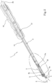
- the reference number 1 designates, in its entirety, a surgical screwdriver.
- the surgical screwdriver 1 is of the fixed tilted-axis type.
- the angle of incidence between the screwing operating axis and the motion actuation axis is predetermined and preferably 25°.
- the surgical screwdriver 1 comprises a first rotating shaft 2 configured to be rotated about a respective longitudinal extension axis "X".
- the first shaft 2 can be rotated manually by the surgical operator, or using appropriate electromechanically controlled motorized systems.
- the first shaft 2 made in the form of a stem, defines the "input" axis of the rotational motion and, in use, is kept coincident with the incision made in the patient.
- the screwdriver 1 also comprises a second rotating shaft 3 extending along a respective development axis "Y" that is transverse to the longitudinal axis "X" of the first shaft 2.
- the second shaft 3 has a shaped end tip 4 to insert into the screw head (not shown in the attached figures as it is not part of the present invention).
- the end tip 4 can have any shape (slotted, cross-shaped, or Allen-shaped, for instance) depending on the seat located on the screw head or other threaded member to be screwed/unscrewed.
- a Torx-type shaped tip 4 configured, therefore, in the shape of a six-pointed star, is shown for purely illustrative, non-limiting, purposes.
- the development axis "Y" of the second shaft 3 therefore defines an "output" axis of the rotational motion and, in use, is arranged coaxially to the longitudinal extension of the screw in order to operate on the screw itself.
- first and second shaft 2 there is also a transmission member 5, which is designed to transfer the rotation from the first shaft 2 to the second shaft 3.
- the transmission member 5 is interposed between respective first ends 2a, 3a, of the shafts 2, 3, opposite, respectively, the second end 2b of the first shaft 2 and the shaped tip 4 of the second shaft 3.
- the transmission member 5 comprises a homokinetic spherical joint 6, which is therefore able to keep the transmission ratio between the first shaft (input axis) and the second shaft (output axis) constant.
- the spherical joint 6 comprises a spherical head 7 having at least one lateral facet 8.
- a plurality of lateral facets 8 adjacent to each other, each of which defines a respective segment of the spherical head 7, is preferably provided.
- the spherical head 7 has a series of arched edges 9 on the outside; these alternate with the facets 8 and extend from two opposite poles of the spherical profile.
- the spherical head 7 is joined to the first end 2a, 3a of one of the shafts 2, 3.
- the head 7 is advantageously made of one piece with the first end 2a of the first shaft 2.
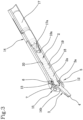
- the spherical head 7 has a circular profile along a section plane coinciding with the longitudinal axis "X" (section plane in Figures 2 and 3 ) and a polygonal, preferably hexagonal, profile along a section plane perpendicular to the longitudinal axis "Y".
- the homokinetic spherical joint 6 also comprises a cavity 10 counter-shaped to the spherical head 7 and partially surrounding the head 7 itself.
- the cavity 10 is in the shape of a cap and is arranged about a substantially hemispherical portion of the head 7.
- the cavity 10 is advantageously located on the first end 3a of the second shaft 3 and preferably made of one piece with the second shaft 3. Furthermore, the cavity 10 has, inside, a lateral wall 11 defining a polygonal, preferably hexagonal, profile and a hemispherical back wall 12. In this way, the head 7 and the cavity 10 are bound in rotation (about the axes "X", “Y” of the respective shafts 2, 3) but free to relatively slide to keep the transverse angle of incidence (at 25° in this embodiment) between the two axes "X", "Y".
- the second shaft has a hemispherical enlargement 13 at the first end 3a, which is designed to internally define the above-mentioned cavity 10. From the hemispherical enlargement 13 the second shaft 3, which terminates in the above-mentioned shaped tip 4, extends in the form of a stem.
- the screwdriver 1 also comprises an internally hollow cylindrical sleeve 14, which has a tubular shape and extends along the longitudinal axis "X" of the first shaft 2.
- the sleeve 14 internally accommodates the homokinetic spherical joint 6 and, at least partially, the shafts 2, 3.
- the second end 2b of the first shaft 2 projects outside a first opening 14a of the sleeve 14.
- This second end 2b is handled by the operator to actuate the rotation of the first shaft 2 or is engaged in torque limiters or other appropriate transmission and/or motorization systems (not shown as they are not part of the present invention).
- the shaped tip 4 of the second shaft 3 also projects outside a second opening 14b of the sleeve 14 opposite to the first opening 14a and opposite to the second end 2b of the first shaft 2.
- the openings 14a, 14b of the sleeve are not mutually coaxial, but staggered to define the angle of incidence between the "X, Y" axes.
- the second opening 14b defines the orientation of the development axis "Y" of the second shaft 3, binding this position with respect to the longitudinal axis "X" of the first shaft.
- the sleeve 14 comprises a projection 15 defining a spherical outer surface for accommodating the homokinetic spherical joint 6.
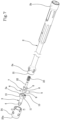
- the projection 15 preferably consists of two hemispheres that can be coupled to each other as highlighted in the exploded view in Figure 4 .
- the second opening 14b of the sleeve 14 is located on the outer surface of the projection 15.
- the projection accommodates the enlargement 13 of the second shaft 3 so that the entire joint 6, during rotation, does not come into contact with the patient's soft tissue surrounding the clamping screw.
- only the shaped tip 4 projecting from the sleeve 14 is the only rotating member inside the patient's body. All the rotating members (the shafts and the joint) are advantageously protected inside the sleeve 14. In this situation, it should be noted that the second end 2b of the first shaft 2 remains outside the patient's body.
- an ergonomic portion 16 which is located on the outer surface of the sleeve 14 near the second end 2b of the first shaft 2, is provided to hold the screwdriver 1 in place.
- the ergonomic portion 16 enables you to manually hold the sleeve with respect to the incision and with respect to the patient, and, at the same time, to unscrew/screw the screw by operating on the first shaft 2.
- the first shaft 2 is made of two portions 17, 18 coaxially joined to each other inside the sleeve 14 and made in the form of respective rods.
- the second end 2b of the first shaft 2 is located in a first portion 17 distal from the second shaft 3.
- the first portion 17 also has a shaped pin 17a, which can be reversibly joined to a respective shaped seat 18a of the second portion 18.
- the second portion 18 has, on the opposite side of the shaped seat 18a, the above-mentioned spherical head 7.
- the second portion 18 is advantageously held inside the sleeve 14 by means of a connector 19 ( Figure 4 ) that can be inserted into transverse holes located in the sleeve 14 and through an annular guide 20 located on the second portion 18.
- the first portion 17, instead, is held manually inside the sleeve 14 and pushed against the second portion 18 to define the coupling between the pin 17a and the seat 18, which guarantees the transmission of the rotation between the first and second portion 17, 18.
- the first portion 17 can be removed from the sleeve 14 and possibly replaced with other functionally equivalent rods.
- a variably tilted-axis screwdriver is provided.
- the orientation of the shaped tip 4, and the entire second shaft 3, can be changed according to the various needs of their use and within a predetermined range of angles between the two axes "X, Y".
- the sleeve 14 can also be used for this embodiment. However, for the sake of clarity, the second embodiment, without the sleeve 14, is shown in the attached figures.
- the first shaft 2 is made of one piece and the respective first end 2a is equipped with a circular seat 21 coaxial to the longitudinal axis "X".
- the spherical head 7 is equipped with a coupling pin 22 projecting from the opposite side of the cavity 10 and accommodated inside the circular seat 21.
- an elastic thrust member 23 is provided, interposed between the circular seat 21 and the coupling pin 22, to enable the movement of the spherical head 7 towards the first shaft 2 as better explained later on.
- the first end 2a of the first shaft 2 is coaxially engaged to a hollow cylindrical body 24 to internally gather the homokinetic spherical joint 6 (as better shown in Figure 6 ).
- the cylindrical body 24 has a through opening 25 through which the second shaft 3 and the respective shaped tip 4 partially project. It should be noted that the through opening 25 is much wider than the thickness of the second shaft 3 to allow the second shaft 3 to move inside the opening 25 and to orient the shaped tip 4 by changing the angle of incidence between the axes "X, Y".
- the second shaft 3 is oriented in a plurality of operating configurations, each of which is representative of a respective angle of incidence between the longitudinal axis "X" of the first shaft 2 and the development axis "Y" of the second shaft 3.
- the tilt of the second shaft 3 can, advantageously, be adjusted according to the position of the screw to be screwed/unscrewed, regardless of the position of the first shaft 2.
- the through opening 25 of the cylindrical body 24 is defined by a perimeter rim 25a that has a width smaller than the diameter of the hemispherical enlargement 13.
- the second shaft 3 is bound in rotation to the first shaft 2 and the head 7 is pushed against the cavity 10 by the elastic member 23. In this way, it is possible to keep the screwdriver 1 compressed against the respective screw, defining a pre-load action of the member 23, in which the shaped tip 4 remains inserted so it is pushed against the seat of the screw head.
- the elastic member 23 keeps the shaped tip 4 pressed against the screw, defining a rotational binding between the second shaft 3 and the screw itself.
- the screwdriver 1 described above overcomes the drawbacks of the prior art and entails important advantages.
- the homokinetic spherical joint enables the transmission ratio between the angular velocity of the first shaft 2 and the second shaft 3 to be kept constant.
- the rotational movement is, advantageously, more homogeneous, smooth, and, therefore, more precise during the tightening of the screws.
- the angle of incidence can be adjusted according to the position of the screw.
- the screwdriver 1 is, therefore, very versatile and can be adjusted to the various types of screws and their insertion positions.
- a further significant advantage is the very small overall size, especially in the positioning area of the transmission member 5.
- the surgical operator can, advantageously, make an incision of a very limited size, thus facilitating the minimum invasiveness of the operation.
- another important advantage of the present invention is due to the absence of projecting portions that, when rotating, can interfere with the tissues surrounding the clamping screws.
- the spherical joint 6 is always contained inside the sleeve 14 or inside the cylindrical body 24. There is, therefore, no risk of direct contact with this moving part and the soft tissue.
- the presence of spherical surfaces and, therefore, the absence of outer edges eliminates any possible damage to the soft tissues resulting from unintentional contact between the screwdriver 1 and the tissues themselves.
Landscapes
- Health & Medical Sciences (AREA)
- Engineering & Computer Science (AREA)
- Life Sciences & Earth Sciences (AREA)
- Mechanical Engineering (AREA)
- Orthopedic Medicine & Surgery (AREA)
- Surgery (AREA)
- Heart & Thoracic Surgery (AREA)
- Biomedical Technology (AREA)
- Nuclear Medicine, Radiotherapy & Molecular Imaging (AREA)
- Medical Informatics (AREA)
- Molecular Biology (AREA)
- Animal Behavior & Ethology (AREA)
- General Health & Medical Sciences (AREA)
- Public Health (AREA)
- Veterinary Medicine (AREA)
- Surgical Instruments (AREA)
- Details Of Spanners, Wrenches, And Screw Drivers And Accessories (AREA)
- Materials For Medical Uses (AREA)
Claims (12)
- Tournevis chirurgical comprenant :- un premier arbre rotatif (2) configuré pour tourner autour d'un axe longitudinal respectif (X) ;- un deuxième arbre rotatif (3) s'étendant le long d'un axe de développement respectif (Y) et ayant un embout d'extrémité profilé (4) qui peut être inséré dans la tête d'une vis ;- un élément de transmission (5) ayant un joint sphérique homocinétique (6) interposé entre les premières extrémités respectives (2a, 3a) des arbres (2, 3) pour transférer la rotation du premier arbre (2) au deuxième arbre (3) ;- un manchon cylindrique (14) qui est creux intérieurement pour loger au moins partiellement lesdits arbres (2, 3) et ledit joint sphérique homocinétique (6) ;ledit premier arbre (2) ayant une deuxième extrémité (2b) opposée à la première (2a) et faisant saillie hors d'une première ouverture (14a) du manchon (14) ; ledit embout profilé (4) du deuxième arbre (3) faisant saillie hors d'une deuxième ouverture (14b) du manchon (14) opposée à la première ouverture (14a) ;caractérisé en ce que ledit premier arbre (2) comprend une première partie (17) et une deuxième partie (18) configurées pour être unies coaxialement l'une à l'autre à l'intérieur du manchon (14) ; ladite deuxième extrémité (2b) du premier arbre (2) étant située dans la première partie (17) qui est distale par rapport au deuxième arbre (3) ;la première partie (17) ayant une broche profilée (17a) configurée pour être unie de manière réversible à un siège profilé respectif (18a) de la deuxième partie (18), de sorte que la première partie puisse être retirée du manchon (14).
- Tournevis selon la revendication précédente, caractérisé en ce que ledit joint sphérique (6) comprend une tête sphérique (7) ayant au moins une facette latérale (8) et une cavité (10) contreprofilée par rapport à ladite tête (7) et entourant partiellement la tête (7).
- Tournevis selon la revendication précédente, caractérisé en ce que ladite tête (7) comprend une pluralité de facettes latérales (8) adjacentes les unes aux autres et chacune desquelles définissant un segment respectif de la tête sphérique (7) ; ladite tête (7) comprenant en outre une pluralité de bordures (9) dont chacune est interposée entre deux facettes adjacentes (8).
- Tournevis selon la revendication 2 ou 3, caractérisé en ce que ladite tête sphérique (7) est unie à la première extrémité (2a, 3a) de l'un desdits arbres (2, 3) et en ce qu'elle comprend un profil circulaire le long d'un plan de section coïncidant avec l'axe (X, Y) de l'arbre respectif (2, 3), et un profil polygonal le long d'un plan de section perpendiculaire à l'axe (X, Y).
- Tournevis selon l'une quelconque des revendications 2 à 4, caractérisé en ce que ladite tête sphérique (7) est unie à la première extrémité (2a) du premier arbre (2) et ladite cavité (10) est située sur la première extrémité (3a) du deuxième arbre (3) ; ladite première extrémité (3a) du deuxième arbre (3) étant agencée du côté opposé par rapport audit embout profilé (4).
- Tournevis selon la revendication 1, caractérisé en ce que lesdites ouvertures (14a, 14b) du manchon (14) ne sont pas coaxiales l'une à l'autre ;
ladite deuxième ouverture (14b) définissant l'axe de développement (Y) du deuxième arbre (3) transversalement à l'axe longitudinal (X) du premier arbre (2). - Tournevis selon la revendication 1, caractérisé en ce que ledit manchon (14) comprend une saillie (15) définissant une surface extérieure sphérique pour loger ledit joint sphérique (6) ; ladite deuxième ouverture (14b) du manchon (14) étant située sur la surface extérieure de la saillie (15).
- Tournevis selon la revendication 1, caractérisé en ce que ledit manchon (14) comprend une partie ergonomique (16) agencée sur une surface extérieure du manchon (14) qui est proche de la deuxième extrémité (2b) du premier arbre (2) ;
lesdits arbres (2, 3) pouvant être tournés à l'intérieur du manchon (14) autour des axes respectifs (X, Y) et par rapport au manchon (14). - Tournevis selon la revendication 1, caractérisé en ce que ladite première extrémité (2a) du premier arbre (2) comprend un siège circulaire (21) qui est coaxial audit axe longitudinal (X) du premier arbre (2) ; ladite tête sphérique (7) ayant une broche d'accouplement (22) faisant saillie de la tête (7) et logée dans ledit siège circulaire (21).
- Tournevis selon la revendication précédente, caractérisé en ce qu'il comprend en outre un corps cylindrique (24) qui est creux intérieurement et en prise coaxiale avec la première extrémité (2a) du premier arbre (2) ; ledit joint sphérique homocinétique (6) étant logé à l'intérieur dudit corps cylindrique (24).
- Tournevis selon la revendication précédente, caractérisé en ce que ledit corps cylindrique (24) comprend une ouverture traversante (25) à travers laquelle l'embout profilé (4) fait saillie ; ledit deuxième arbre (3) étant mobile à l'intérieur de ladite ouverture (25) pour être orienté dans une pluralité de configurations opérationnelles, dont chacune est représentative d'un angle d'incidence respectif entre l'axe longitudinal (X) du premier arbre (2) et l'axe de développement (Y) du deuxième arbre (3).
- Tournevis selon la revendication précédente, caractérisé en ce qu'il comprend en outre un élément de poussée élastique (23) interposé entre le siège circulaire (21) du premier arbre (2) et la broche d'accouplement (22) pour permettre le mouvement du deuxième arbre (3) et du joint sphérique homocinétique (6) vers le premier arbre (2).
Applications Claiming Priority (2)
| Application Number | Priority Date | Filing Date | Title |
|---|---|---|---|
| IT102018000020290A IT201800020290A1 (it) | 2018-12-20 | 2018-12-20 | Cacciavite chirurgico |
| PCT/IB2019/060892 WO2020128812A1 (fr) | 2018-12-20 | 2019-12-17 | Tournevis chirurgical |
Publications (2)
| Publication Number | Publication Date |
|---|---|
| EP3897424A1 EP3897424A1 (fr) | 2021-10-27 |
| EP3897424B1 true EP3897424B1 (fr) | 2025-03-12 |
Family
ID=65951952
Family Applications (1)
| Application Number | Title | Priority Date | Filing Date |
|---|---|---|---|
| EP19816489.9A Active EP3897424B1 (fr) | 2018-12-20 | 2019-12-17 | Tournevis chirurgical |
Country Status (7)
| Country | Link |
|---|---|
| US (1) | US12082862B2 (fr) |
| EP (1) | EP3897424B1 (fr) |
| JP (1) | JP7470692B2 (fr) |
| AU (1) | AU2019407130B2 (fr) |
| ES (1) | ES3028607T3 (fr) |
| IT (1) | IT201800020290A1 (fr) |
| WO (1) | WO2020128812A1 (fr) |
Families Citing this family (1)
| Publication number | Priority date | Publication date | Assignee | Title |
|---|---|---|---|---|
| IT201800020350A1 (it) | 2018-12-20 | 2020-06-20 | Medacta Int Sa | Cacciavite chirurgico |
Family Cites Families (14)
| Publication number | Priority date | Publication date | Assignee | Title |
|---|---|---|---|---|
| US1392220A (en) | 1920-12-17 | 1921-09-27 | Quint Michael | Socket-wrench |
| JPS58143165U (ja) * | 1982-03-24 | 1983-09-27 | 中山 栄太郎 | レンチ |
| US5797918A (en) * | 1991-12-13 | 1998-08-25 | David A. McGuire | Flexible surgical screwdriver and methods of arthroscopic ligament reconstruction |
| US6347564B1 (en) * | 1998-09-28 | 2002-02-19 | Quintino Matthew Ciocca | Fastener-driving hand tool having an angularly displaceable bit retainer |
| DE10011678B4 (de) * | 2000-03-10 | 2007-07-26 | Richard Wolf Gmbh | Chirurgisches Instrument zum Applizieren von Implantaten |
| DE20009358U1 (de) * | 2000-05-24 | 2000-08-10 | Wiha Werkzeuge Willi Hahn GmbH & Co. KG, 78136 Schonach | Aufnahmekopf für ein Werkzeug mit einer Schlitz- oder Mehrkantbetätigungsspitze |
| US7082864B1 (en) | 2005-04-21 | 2006-08-01 | International Paper Company | Tool with protective sheath |
| EP2453820B1 (fr) | 2009-07-15 | 2016-06-29 | Orthohelix Surgical Designs, Inc. | Système d'implants orthopédiques comprenant un mécanisme de blocage à axe variable |
| EP2536538B1 (fr) | 2010-02-16 | 2018-09-05 | Milwaukee Electric Tool Corporation | Accessoire d'entraînement |
| US20120109142A1 (en) | 2010-10-27 | 2012-05-03 | Alan Dayan | Surgical Screwdriver |
| US8986307B2 (en) | 2012-07-10 | 2015-03-24 | X-Spine Systems, Inc. | Surgical instrument with pivotable implant holder |
| US20140018816A1 (en) * | 2012-07-12 | 2014-01-16 | Synthes Usa, Llc | Torque transmitting ball joint driver having a rigid fixation mechanism |
| US20180325574A1 (en) | 2017-03-31 | 2018-11-15 | Spineology Inc. | Swivel drive system for screw insertion |
| IT201800020350A1 (it) | 2018-12-20 | 2020-06-20 | Medacta Int Sa | Cacciavite chirurgico |
-
2018
- 2018-12-20 IT IT102018000020290A patent/IT201800020290A1/it unknown
-
2019
- 2019-12-17 AU AU2019407130A patent/AU2019407130B2/en active Active
- 2019-12-17 US US17/415,613 patent/US12082862B2/en active Active
- 2019-12-17 ES ES19816489T patent/ES3028607T3/es active Active
- 2019-12-17 WO PCT/IB2019/060892 patent/WO2020128812A1/fr not_active Ceased
- 2019-12-17 EP EP19816489.9A patent/EP3897424B1/fr active Active
- 2019-12-17 JP JP2021535599A patent/JP7470692B2/ja active Active
Also Published As
| Publication number | Publication date |
|---|---|
| AU2019407130A1 (en) | 2021-07-08 |
| IT201800020290A1 (it) | 2020-06-20 |
| WO2020128812A1 (fr) | 2020-06-25 |
| US12082862B2 (en) | 2024-09-10 |
| AU2019407130B2 (en) | 2022-12-15 |
| US20220054178A1 (en) | 2022-02-24 |
| JP7470692B2 (ja) | 2024-04-18 |
| ES3028607T3 (en) | 2025-06-19 |
| EP3897424A1 (fr) | 2021-10-27 |
| JP2022515138A (ja) | 2022-02-17 |
Similar Documents
| Publication | Publication Date | Title |
|---|---|---|
| US12446898B2 (en) | Torque transmitting ball joint driver having a rigid fixation mechanism | |
| US12383323B2 (en) | Inserter guide and driver system | |
| US10682745B2 (en) | Surgical devices and methods for driving an implant and applying counter torque | |
| US20090306719A1 (en) | Structure and method for driving a pedicle screw with an attached support rod for spinal osteosynthesis | |
| US20080015601A1 (en) | Reduction device and method of use | |
| US20160287409A1 (en) | Insertion instrument with articulating wrist | |
| US20150320428A1 (en) | Acetabular Reamer | |
| CN110214068A (zh) | 轴精确的螺丝刀 | |
| US12575870B2 (en) | Surgical tool for positioning a surgical device, surgical device and kit | |
| EP3897424B1 (fr) | Tournevis chirurgical | |
| US12042197B2 (en) | Surgical screwdriver |
Legal Events
| Date | Code | Title | Description |
|---|---|---|---|
| STAA | Information on the status of an ep patent application or granted ep patent |
Free format text: STATUS: UNKNOWN |
|
| STAA | Information on the status of an ep patent application or granted ep patent |
Free format text: STATUS: THE INTERNATIONAL PUBLICATION HAS BEEN MADE |
|
| PUAI | Public reference made under article 153(3) epc to a published international application that has entered the european phase |
Free format text: ORIGINAL CODE: 0009012 |
|
| STAA | Information on the status of an ep patent application or granted ep patent |
Free format text: STATUS: REQUEST FOR EXAMINATION WAS MADE |
|
| 17P | Request for examination filed |
Effective date: 20210524 |
|
| AK | Designated contracting states |
Kind code of ref document: A1 Designated state(s): AL AT BE BG CH CY CZ DE DK EE ES FI FR GB GR HR HU IE IS IT LI LT LU LV MC MK MT NL NO PL PT RO RS SE SI SK SM TR |
|
| DAV | Request for validation of the european patent (deleted) | ||
| DAX | Request for extension of the european patent (deleted) | ||
| P01 | Opt-out of the competence of the unified patent court (upc) registered |
Effective date: 20230630 |
|
| GRAP | Despatch of communication of intention to grant a patent |
Free format text: ORIGINAL CODE: EPIDOSNIGR1 |
|
| STAA | Information on the status of an ep patent application or granted ep patent |
Free format text: STATUS: GRANT OF PATENT IS INTENDED |
|
| RIC1 | Information provided on ipc code assigned before grant |
Ipc: B25B 23/00 20060101ALI20241002BHEP Ipc: B25B 13/48 20060101ALI20241002BHEP Ipc: A61B 17/88 20060101AFI20241002BHEP |
|
| INTG | Intention to grant announced |
Effective date: 20241014 |
|
| GRAS | Grant fee paid |
Free format text: ORIGINAL CODE: EPIDOSNIGR3 |
|
| GRAA | (expected) grant |
Free format text: ORIGINAL CODE: 0009210 |
|
| STAA | Information on the status of an ep patent application or granted ep patent |
Free format text: STATUS: THE PATENT HAS BEEN GRANTED |
|
| AK | Designated contracting states |
Kind code of ref document: B1 Designated state(s): AL AT BE BG CH CY CZ DE DK EE ES FI FR GB GR HR HU IE IS IT LI LT LU LV MC MK MT NL NO PL PT RO RS SE SI SK SM TR |
|
| REG | Reference to a national code |
Ref country code: GB Ref legal event code: FG4D |
|
| REG | Reference to a national code |
Ref country code: CH Ref legal event code: EP |
|
| REG | Reference to a national code |
Ref country code: DE Ref legal event code: R096 Ref document number: 602019067236 Country of ref document: DE |
|
| REG | Reference to a national code |
Ref country code: IE Ref legal event code: FG4D |
|
| REG | Reference to a national code |
Ref country code: ES Ref legal event code: FG2A Ref document number: 3028607 Country of ref document: ES Kind code of ref document: T3 Effective date: 20250619 |
|
| PG25 | Lapsed in a contracting state [announced via postgrant information from national office to epo] |
Ref country code: RS Free format text: LAPSE BECAUSE OF FAILURE TO SUBMIT A TRANSLATION OF THE DESCRIPTION OR TO PAY THE FEE WITHIN THE PRESCRIBED TIME-LIMIT Effective date: 20250612 |
|
| PG25 | Lapsed in a contracting state [announced via postgrant information from national office to epo] |
Ref country code: FI Free format text: LAPSE BECAUSE OF FAILURE TO SUBMIT A TRANSLATION OF THE DESCRIPTION OR TO PAY THE FEE WITHIN THE PRESCRIBED TIME-LIMIT Effective date: 20250312 |
|
| REG | Reference to a national code |
Ref country code: LT Ref legal event code: MG9D |
|
| PG25 | Lapsed in a contracting state [announced via postgrant information from national office to epo] |
Ref country code: NO Free format text: LAPSE BECAUSE OF FAILURE TO SUBMIT A TRANSLATION OF THE DESCRIPTION OR TO PAY THE FEE WITHIN THE PRESCRIBED TIME-LIMIT Effective date: 20250612 |
|
| PG25 | Lapsed in a contracting state [announced via postgrant information from national office to epo] |
Ref country code: HR Free format text: LAPSE BECAUSE OF FAILURE TO SUBMIT A TRANSLATION OF THE DESCRIPTION OR TO PAY THE FEE WITHIN THE PRESCRIBED TIME-LIMIT Effective date: 20250312 |
|
| REG | Reference to a national code |
Ref country code: NL Ref legal event code: MP Effective date: 20250312 |
|
| PG25 | Lapsed in a contracting state [announced via postgrant information from national office to epo] |
Ref country code: LV Free format text: LAPSE BECAUSE OF FAILURE TO SUBMIT A TRANSLATION OF THE DESCRIPTION OR TO PAY THE FEE WITHIN THE PRESCRIBED TIME-LIMIT Effective date: 20250312 |
|
| PG25 | Lapsed in a contracting state [announced via postgrant information from national office to epo] |
Ref country code: BG Free format text: LAPSE BECAUSE OF FAILURE TO SUBMIT A TRANSLATION OF THE DESCRIPTION OR TO PAY THE FEE WITHIN THE PRESCRIBED TIME-LIMIT Effective date: 20250312 Ref country code: GR Free format text: LAPSE BECAUSE OF FAILURE TO SUBMIT A TRANSLATION OF THE DESCRIPTION OR TO PAY THE FEE WITHIN THE PRESCRIBED TIME-LIMIT Effective date: 20250613 |
|
| REG | Reference to a national code |
Ref country code: AT Ref legal event code: MK05 Ref document number: 1774367 Country of ref document: AT Kind code of ref document: T Effective date: 20250312 |
|
| PG25 | Lapsed in a contracting state [announced via postgrant information from national office to epo] |
Ref country code: NL Free format text: LAPSE BECAUSE OF FAILURE TO SUBMIT A TRANSLATION OF THE DESCRIPTION OR TO PAY THE FEE WITHIN THE PRESCRIBED TIME-LIMIT Effective date: 20250312 |
|
| PG25 | Lapsed in a contracting state [announced via postgrant information from national office to epo] |
Ref country code: SE Free format text: LAPSE BECAUSE OF FAILURE TO SUBMIT A TRANSLATION OF THE DESCRIPTION OR TO PAY THE FEE WITHIN THE PRESCRIBED TIME-LIMIT Effective date: 20250312 |
|
| PG25 | Lapsed in a contracting state [announced via postgrant information from national office to epo] |
Ref country code: SM Free format text: LAPSE BECAUSE OF FAILURE TO SUBMIT A TRANSLATION OF THE DESCRIPTION OR TO PAY THE FEE WITHIN THE PRESCRIBED TIME-LIMIT Effective date: 20250312 |
|
| PG25 | Lapsed in a contracting state [announced via postgrant information from national office to epo] |
Ref country code: PT Free format text: LAPSE BECAUSE OF FAILURE TO SUBMIT A TRANSLATION OF THE DESCRIPTION OR TO PAY THE FEE WITHIN THE PRESCRIBED TIME-LIMIT Effective date: 20250714 |
|
| PG25 | Lapsed in a contracting state [announced via postgrant information from national office to epo] |
Ref country code: PL Free format text: LAPSE BECAUSE OF FAILURE TO SUBMIT A TRANSLATION OF THE DESCRIPTION OR TO PAY THE FEE WITHIN THE PRESCRIBED TIME-LIMIT Effective date: 20250312 |
|
| PG25 | Lapsed in a contracting state [announced via postgrant information from national office to epo] |
Ref country code: AT Free format text: LAPSE BECAUSE OF FAILURE TO SUBMIT A TRANSLATION OF THE DESCRIPTION OR TO PAY THE FEE WITHIN THE PRESCRIBED TIME-LIMIT Effective date: 20250312 |
|
| PG25 | Lapsed in a contracting state [announced via postgrant information from national office to epo] |
Ref country code: CZ Free format text: LAPSE BECAUSE OF FAILURE TO SUBMIT A TRANSLATION OF THE DESCRIPTION OR TO PAY THE FEE WITHIN THE PRESCRIBED TIME-LIMIT Effective date: 20250312 Ref country code: EE Free format text: LAPSE BECAUSE OF FAILURE TO SUBMIT A TRANSLATION OF THE DESCRIPTION OR TO PAY THE FEE WITHIN THE PRESCRIBED TIME-LIMIT Effective date: 20250312 |
|
| PG25 | Lapsed in a contracting state [announced via postgrant information from national office to epo] |
Ref country code: RO Free format text: LAPSE BECAUSE OF FAILURE TO SUBMIT A TRANSLATION OF THE DESCRIPTION OR TO PAY THE FEE WITHIN THE PRESCRIBED TIME-LIMIT Effective date: 20250312 |
|
| PG25 | Lapsed in a contracting state [announced via postgrant information from national office to epo] |
Ref country code: SK Free format text: LAPSE BECAUSE OF FAILURE TO SUBMIT A TRANSLATION OF THE DESCRIPTION OR TO PAY THE FEE WITHIN THE PRESCRIBED TIME-LIMIT Effective date: 20250312 |
|
| PG25 | Lapsed in a contracting state [announced via postgrant information from national office to epo] |
Ref country code: IS Free format text: LAPSE BECAUSE OF FAILURE TO SUBMIT A TRANSLATION OF THE DESCRIPTION OR TO PAY THE FEE WITHIN THE PRESCRIBED TIME-LIMIT Effective date: 20250712 |
|
| REG | Reference to a national code |
Ref country code: DE Ref legal event code: R097 Ref document number: 602019067236 Country of ref document: DE |
|
| REG | Reference to a national code |
Ref country code: CH Ref legal event code: U11 Free format text: ST27 STATUS EVENT CODE: U-0-0-U10-U11 (AS PROVIDED BY THE NATIONAL OFFICE) Effective date: 20260101 |
|
| PGFP | Annual fee paid to national office [announced via postgrant information from national office to epo] |
Ref country code: GB Payment date: 20251223 Year of fee payment: 7 |
|
| PG25 | Lapsed in a contracting state [announced via postgrant information from national office to epo] |
Ref country code: DK Free format text: LAPSE BECAUSE OF FAILURE TO SUBMIT A TRANSLATION OF THE DESCRIPTION OR TO PAY THE FEE WITHIN THE PRESCRIBED TIME-LIMIT Effective date: 20250312 |
|
| PGFP | Annual fee paid to national office [announced via postgrant information from national office to epo] |
Ref country code: IT Payment date: 20251222 Year of fee payment: 7 |
|
| PGFP | Annual fee paid to national office [announced via postgrant information from national office to epo] |
Ref country code: FR Payment date: 20251223 Year of fee payment: 7 |
|
| PLBE | No opposition filed within time limit |
Free format text: ORIGINAL CODE: 0009261 |
|
| STAA | Information on the status of an ep patent application or granted ep patent |
Free format text: STATUS: NO OPPOSITION FILED WITHIN TIME LIMIT |
|
| REG | Reference to a national code |
Ref country code: CH Ref legal event code: L10 Free format text: ST27 STATUS EVENT CODE: U-0-0-L10-L00 (AS PROVIDED BY THE NATIONAL OFFICE) Effective date: 20260121 |
|
| 26N | No opposition filed |
Effective date: 20251215 |
|
| PGFP | Annual fee paid to national office [announced via postgrant information from national office to epo] |
Ref country code: ES Payment date: 20260122 Year of fee payment: 7 |
|
| PGFP | Annual fee paid to national office [announced via postgrant information from national office to epo] |
Ref country code: DE Payment date: 20251229 Year of fee payment: 7 |
|
| PGFP | Annual fee paid to national office [announced via postgrant information from national office to epo] |
Ref country code: CH Payment date: 20260101 Year of fee payment: 7 |