EP3897470B1 - Elastisches flächenmaterial, bandage daraus und verfahren zu dessen herstellung - Google Patents
Elastisches flächenmaterial, bandage daraus und verfahren zu dessen herstellung Download PDFInfo
- Publication number
- EP3897470B1 EP3897470B1 EP19817220.7A EP19817220A EP3897470B1 EP 3897470 B1 EP3897470 B1 EP 3897470B1 EP 19817220 A EP19817220 A EP 19817220A EP 3897470 B1 EP3897470 B1 EP 3897470B1
- Authority
- EP
- European Patent Office
- Prior art keywords
- sheet material
- functional element
- limiting
- limiting element
- surface material
- Prior art date
- Legal status (The legal status is an assumption and is not a legal conclusion. Google has not performed a legal analysis and makes no representation as to the accuracy of the status listed.)
- Active
Links
Images


Classifications
-
- A—HUMAN NECESSITIES
- A61—MEDICAL OR VETERINARY SCIENCE; HYGIENE
- A61F—FILTERS IMPLANTABLE INTO BLOOD VESSELS; PROSTHESES; DEVICES PROVIDING PATENCY TO, OR PREVENTING COLLAPSING OF, TUBULAR STRUCTURES OF THE BODY, e.g. STENTS; ORTHOPAEDIC, NURSING OR CONTRACEPTIVE DEVICES; FOMENTATION; TREATMENT OR PROTECTION OF EYES OR EARS; BANDAGES, DRESSINGS OR ABSORBENT PADS; FIRST-AID KITS
- A61F5/00—Orthopaedic methods or devices for non-surgical treatment of bones or joints; Nursing devices ; Anti-rape devices
- A61F5/01—Orthopaedic devices, e.g. long-term immobilising or pressure directing devices for treating broken or deformed bones such as splints, casts or braces
- A61F5/0102—Orthopaedic devices, e.g. long-term immobilising or pressure directing devices for treating broken or deformed bones such as splints, casts or braces specially adapted for correcting deformities of the limbs or for supporting them; Ortheses, e.g. with articulations
- A61F5/0104—Orthopaedic devices, e.g. long-term immobilising or pressure directing devices for treating broken or deformed bones such as splints, casts or braces specially adapted for correcting deformities of the limbs or for supporting them; Ortheses, e.g. with articulations without articulation
- A61F5/0106—Orthopaedic devices, e.g. long-term immobilising or pressure directing devices for treating broken or deformed bones such as splints, casts or braces specially adapted for correcting deformities of the limbs or for supporting them; Ortheses, e.g. with articulations without articulation for the knees
- A61F5/0109—Sleeve-like structures
-
- A—HUMAN NECESSITIES
- A61—MEDICAL OR VETERINARY SCIENCE; HYGIENE
- A61F—FILTERS IMPLANTABLE INTO BLOOD VESSELS; PROSTHESES; DEVICES PROVIDING PATENCY TO, OR PREVENTING COLLAPSING OF, TUBULAR STRUCTURES OF THE BODY, e.g. STENTS; ORTHOPAEDIC, NURSING OR CONTRACEPTIVE DEVICES; FOMENTATION; TREATMENT OR PROTECTION OF EYES OR EARS; BANDAGES, DRESSINGS OR ABSORBENT PADS; FIRST-AID KITS
- A61F13/00—Bandages or dressings; Absorbent pads
- A61F13/01—Non-adhesive bandages or dressings
- A61F13/01008—Non-adhesive bandages or dressings characterised by the material
- A61F13/01017—Non-adhesive bandages or dressings characterised by the material synthetic, e.g. polymer based
-
- A—HUMAN NECESSITIES
- A61—MEDICAL OR VETERINARY SCIENCE; HYGIENE
- A61F—FILTERS IMPLANTABLE INTO BLOOD VESSELS; PROSTHESES; DEVICES PROVIDING PATENCY TO, OR PREVENTING COLLAPSING OF, TUBULAR STRUCTURES OF THE BODY, e.g. STENTS; ORTHOPAEDIC, NURSING OR CONTRACEPTIVE DEVICES; FOMENTATION; TREATMENT OR PROTECTION OF EYES OR EARS; BANDAGES, DRESSINGS OR ABSORBENT PADS; FIRST-AID KITS
- A61F13/00—Bandages or dressings; Absorbent pads
- A61F13/01—Non-adhesive bandages or dressings
- A61F13/01021—Non-adhesive bandages or dressings characterised by the structure of the dressing
- A61F13/01029—Non-adhesive bandages or dressings characterised by the structure of the dressing made of multiple layers
-
- A—HUMAN NECESSITIES
- A61—MEDICAL OR VETERINARY SCIENCE; HYGIENE
- A61F—FILTERS IMPLANTABLE INTO BLOOD VESSELS; PROSTHESES; DEVICES PROVIDING PATENCY TO, OR PREVENTING COLLAPSING OF, TUBULAR STRUCTURES OF THE BODY, e.g. STENTS; ORTHOPAEDIC, NURSING OR CONTRACEPTIVE DEVICES; FOMENTATION; TREATMENT OR PROTECTION OF EYES OR EARS; BANDAGES, DRESSINGS OR ABSORBENT PADS; FIRST-AID KITS
- A61F13/00—Bandages or dressings; Absorbent pads
- A61F13/01—Non-adhesive bandages or dressings
- A61F13/01034—Non-adhesive bandages or dressings characterised by a property
- A61F13/01038—Flexibility, stretchability or elasticity
-
- A—HUMAN NECESSITIES
- A61—MEDICAL OR VETERINARY SCIENCE; HYGIENE
- A61F—FILTERS IMPLANTABLE INTO BLOOD VESSELS; PROSTHESES; DEVICES PROVIDING PATENCY TO, OR PREVENTING COLLAPSING OF, TUBULAR STRUCTURES OF THE BODY, e.g. STENTS; ORTHOPAEDIC, NURSING OR CONTRACEPTIVE DEVICES; FOMENTATION; TREATMENT OR PROTECTION OF EYES OR EARS; BANDAGES, DRESSINGS OR ABSORBENT PADS; FIRST-AID KITS
- A61F13/00—Bandages or dressings; Absorbent pads
- A61F13/06—Bandages or dressings; Absorbent pads specially adapted for feet or legs; Corn-pads; Corn-rings
- A61F13/061—Bandages or dressings; Absorbent pads specially adapted for feet or legs; Corn-pads; Corn-rings for knees
-
- A—HUMAN NECESSITIES
- A61—MEDICAL OR VETERINARY SCIENCE; HYGIENE
- A61F—FILTERS IMPLANTABLE INTO BLOOD VESSELS; PROSTHESES; DEVICES PROVIDING PATENCY TO, OR PREVENTING COLLAPSING OF, TUBULAR STRUCTURES OF THE BODY, e.g. STENTS; ORTHOPAEDIC, NURSING OR CONTRACEPTIVE DEVICES; FOMENTATION; TREATMENT OR PROTECTION OF EYES OR EARS; BANDAGES, DRESSINGS OR ABSORBENT PADS; FIRST-AID KITS
- A61F13/00—Bandages or dressings; Absorbent pads
- A61F13/06—Bandages or dressings; Absorbent pads specially adapted for feet or legs; Corn-pads; Corn-rings
- A61F13/08—Elastic stockings; for contracting aneurisms
-
- A—HUMAN NECESSITIES
- A61—MEDICAL OR VETERINARY SCIENCE; HYGIENE
- A61F—FILTERS IMPLANTABLE INTO BLOOD VESSELS; PROSTHESES; DEVICES PROVIDING PATENCY TO, OR PREVENTING COLLAPSING OF, TUBULAR STRUCTURES OF THE BODY, e.g. STENTS; ORTHOPAEDIC, NURSING OR CONTRACEPTIVE DEVICES; FOMENTATION; TREATMENT OR PROTECTION OF EYES OR EARS; BANDAGES, DRESSINGS OR ABSORBENT PADS; FIRST-AID KITS
- A61F2/00—Filters implantable into blood vessels; Prostheses, i.e. artificial substitutes or replacements for parts of the body; Appliances for connecting them with the body; Devices providing patency to, or preventing collapsing of, tubular structures of the body, e.g. stents
- A61F2/50—Prostheses not implantable in the body
- A61F2/68—Operating or control means
- A61F2/70—Operating or control means electrical
- A61F2/72—Bioelectric control, e.g. myoelectric
-
- A—HUMAN NECESSITIES
- A61—MEDICAL OR VETERINARY SCIENCE; HYGIENE
- A61F—FILTERS IMPLANTABLE INTO BLOOD VESSELS; PROSTHESES; DEVICES PROVIDING PATENCY TO, OR PREVENTING COLLAPSING OF, TUBULAR STRUCTURES OF THE BODY, e.g. STENTS; ORTHOPAEDIC, NURSING OR CONTRACEPTIVE DEVICES; FOMENTATION; TREATMENT OR PROTECTION OF EYES OR EARS; BANDAGES, DRESSINGS OR ABSORBENT PADS; FIRST-AID KITS
- A61F2/00—Filters implantable into blood vessels; Prostheses, i.e. artificial substitutes or replacements for parts of the body; Appliances for connecting them with the body; Devices providing patency to, or preventing collapsing of, tubular structures of the body, e.g. stents
- A61F2/50—Prostheses not implantable in the body
- A61F2/78—Means for protecting prostheses or for attaching them to the body, e.g. bandages, harnesses, straps, or stockings for the limb stump
-
- A—HUMAN NECESSITIES
- A61—MEDICAL OR VETERINARY SCIENCE; HYGIENE
- A61F—FILTERS IMPLANTABLE INTO BLOOD VESSELS; PROSTHESES; DEVICES PROVIDING PATENCY TO, OR PREVENTING COLLAPSING OF, TUBULAR STRUCTURES OF THE BODY, e.g. STENTS; ORTHOPAEDIC, NURSING OR CONTRACEPTIVE DEVICES; FOMENTATION; TREATMENT OR PROTECTION OF EYES OR EARS; BANDAGES, DRESSINGS OR ABSORBENT PADS; FIRST-AID KITS
- A61F2/00—Filters implantable into blood vessels; Prostheses, i.e. artificial substitutes or replacements for parts of the body; Appliances for connecting them with the body; Devices providing patency to, or preventing collapsing of, tubular structures of the body, e.g. stents
- A61F2/50—Prostheses not implantable in the body
- A61F2/78—Means for protecting prostheses or for attaching them to the body, e.g. bandages, harnesses, straps, or stockings for the limb stump
- A61F2/7812—Interface cushioning members placed between the limb stump and the socket, e.g. bandages or stockings for the limb stump
- A61F2002/7837—Sleeves for attaching or protecting, i.e. open ended hoses
Definitions
- the invention relates to an elastic sheet material with a front side and a back side opposite the front side and at least one functional element arranged on the front side, which is connected to the sheet material.
- the invention also relates to a bandage on such a sheet material and a method for producing such a sheet material.
- a sheet material is used in particular as a starting material for producing orthopedic devices or orthoses, in particular for producing cuffs or bandages.
- Cuffs, bandages or orthoses usually have an elastic base body that can be placed around the limb or a joint area.
- a stabilizing element such as a metal splint or a plastic splint, can be arranged on the base body.
- Bandages or cuffs are applied to support or stabilize the joint function or the muscles and ligaments. To do this, the bandage is pulled over the joint or muscles to be protected or wrapped around it and fixed in place.
- bandages allow the limbs connected by the joint to move relative to one another.
- the bandages also have a base body made of a flexible material, such as foam or textile.
- stabilizing elements are arranged on the base body that have increased strength and rigidity compared to the base body, so that in addition to protection against mechanical impact, increased restriction of movement is achieved.
- a flexible bandage with a frame with a surface for application to a body area is known, wherein the frame has a has a large number of openings.
- a fabric or foam can be attached to the frame itself, for example by welding, gluing or sewing.
- the EP 876 130 B1 describes an orthopedic brace having a bracket made from a one-piece injection molded part with regions of varying thickness to conform to the contour of a selected portion of a body limb. A layer of elastic material is mounted within the bracket to cushion the bracket.
- the US 6,024,712 A describes an ankle orthosis with an inner textile part that extends at least partially around an ankle joint.
- An external support is connected to the textile via an injection molding process and provides additional support for the joint against unintentional movements.
- the CA2,398,059 A1 describes an orthopedic support with a flexible inner part and an outer support that is molded directly onto the flexible inner part.
- the WO 2013/072064 A1 describes an orthopedic cuff for use on a body with a flexible base body with at least one stabilizing element made of plastic arranged thereon.
- the stabilizing element has areas with a cross-section that is smaller than the rest of the cross-section, in which the stabilizing element is glued to the base body and/or is integrally connected to the base body.
- the stabilizing element can be applied to a flexible carrier material, in particular sprayed on or back-injected. The carrier material then forms the areas that are integrally connected to the base body.
- the EP 2 090 273 A2 describes a bandage made of a knitted fabric that can have a stabilizing element for a joint. This can be arranged on the outside of the bandage, for example, and then fixed using a quick-release device. It is also possible for the stabilizing element to be arranged in a pocket formed in the bandage.
- the US 2013/0046394 A1 describes a gel liner for a prosthesis.
- a plurality of electrodes for recording myoelectric signals are arranged on the inside of the liner.
- a prosthesis shaft is arranged on the outside of the liner, which surrounds the liner
- the object of the present invention is therefore to provide a surface material, a bandage and a method for producing a surface material which enable a permanent and inexpensive connection of a functional element to the surface material with a high individualization rate.
- this object is achieved by a sheet material having the features of the main claim, a bandage produced therefrom and a method having the features of the independent claim.
- the elastic sheet material according to the invention with a front side and a back side opposite the front side and at least one functional element arranged on the front side, which is connected to the sheet material, provides that on the back of the sheet material opposite the functional element and/or on the front side below the functional element and/or within the sheet material, a limiting element for limiting the elasticity of the sheet material, in particular locally in the area of the functional element, is arranged.
- the back of an elastic sheet material is used in particular for resting on or contacting a skin surface, while a functional element usually has a rigid or protruding structure that better arranged on the outside, i.e. on the side of the surface material facing away from the body.
- the arrangement of a limiting element that limits or eliminates the elasticity of the surface material, at least in the plane of the front and back, has the advantage that even if the material of the functional element does not penetrate as deeply into the structure of the elastic surface material, no tension and no relative movement arise when the textile is stretched and contracted again when the surface material expands radially or longitudinally. Reducing the thickness of the surface material, i.e. moving the back towards the front, is harmless and does not have to be prevented by the limiting element. Limiting the elasticity predominantly in one direction can be achieved by special designs of the limiting element, for example by using a flexible fabric that is tensile in one direction and elastic in the direction oriented perpendicular to it.
- the limiting element prevents or reduces expansion and contraction of the surface material as a carrier for the functional element and thus prevents or reduces relative movement between the functional element and the surface material, since no or reduced stresses are transferred to the bonding surfaces or the connection area of the functional element with the surface material when the surface material is expanded. This prevents the physical connection between the functional element and the surface material from loosening or breaking down, so that the fatigue strength of the connection of the functional element to the surface material is maintained. Surprisingly, it has been shown that even with stiffening only on one side of the surface material, i.e.
- the partial rigidity of the surface material also has the advantage that the elasticity of the end product as a whole is only slightly restricted and only in the areas in which the functional element is arranged. Since the functional elements are usually also rigid in the area of the connection to the elastic surface material, there is no noticeable restriction in the wearing comfort of the surface material when it is processed into an orthopaedic device, for example a bandage or a cuff.
- the limiting element can be arranged on the side opposite the functional element or form an intermediate layer between the functional element and the surface material.
- the surface material is preferably designed as a textile, for example a knitted fabric, scrim or warp-knitted fabric. It can also be designed as a spacer fabric. Alternatively, the surface material can be designed as foam or contain foam components.
- a surface material is considered to be a material that has a predominantly two-dimensional extension, i.e. a large surface area with a low material thickness.
- the limiting element has an outer contour that corresponds to the outer contour of the functional element or at least partially, preferably completely, encloses the outer contour of the functional element. If the outer contour of the limiting element corresponds to the outer contour of the functional element, only a minimal area of the surface material is stiffened, which does not affect the remaining elastic behavior of the surface material. If the surface area of the limiting element is larger than the outer contour of the functional element, a larger area of the surface material is stiffened, which on the one hand makes positioning the functional element easier and on the other hand prevents tension in the edge area of the surface material at the transition to the functional element, thereby providing increased durability.
- the outer contour of the limiting element can also only cover the areas of the functional element that are designed to be rigid.
- Other areas of the functional element, such as springs, which themselves develop sufficient elasticity, can follow the movement of the elastic surface material and do not detach as quickly, so that a limitation of the elasticity of the surface material is not absolutely necessary here.
- the limiting element is preferably integrally connected to the surface material, for example welded or glued.
- the limiting element can be glued or welded onto the surface material as a film, preferably glued or welded over the entire surface. It is also possible for the limiting element to be formed by an adhesive layer or by a large number of adhesive strips or adhesive dots or an adhesive grid that is applied to the surface material so that it adheres to the surface and/or penetrates into the surface material.
- the limiting element can be designed as an inelastic but flexible textile, a penetrating element that penetrates the surface material and forms a projection on the opposite side, in particular the front side, as a conductive textile or band or cable, for example having a metallic thread component, in order to enable sufficient flexibility but at least to reduce or eliminate the elasticity in the partial area in which the limiting element is applied.
- the limiting element can also be designed as a sensor, for example a capacitive sensor, in order to make a functional contribution to the design of an orthopedic component beyond the limiting function with regard to elasticity.
- a further development of the invention provides that several limiting elements are arranged separately from one another on the surface material in order not to restrict the elasticity and flexibility of the entire surface material or to restrict them as little as possible.
- the limiting elements can, for example, be applied one behind the other in a longitudinal extension, separately from one another, to the surface material and secured thereto. It is also possible, in a sleeve-like design of the finished product, to provide limiting elements distributed over the circumference and oriented in the longitudinal direction, which enable radial expansion in the intermediate areas between the limiting elements, but prevent elongation in the longitudinal extension at least in some areas.
- the limiting elements or the limiting element are preferably designed to be flexible in order to adapt the surface material to different surfaces, in particular body surfaces. This means that the limiting element is flexible, but allows no or only a reduced change in length in the plane.
- a further development of the invention provides that the functional element is printed on the surface textile or applied to the surface material by means of an additive manufacturing process, i.e. applied to the surface textile in a layer-by-layer application process or additive manufacturing process and connected there in a form-fitting and/or material-fitting manner.
- the functional element can, for example, be formed as an elastomer or from an elastomer and in particular applied to the textile in an additive manufacturing process.
- additive manufacturing processes e.g. so-called 3D printing, for example with an SLA printer or FDM printer, it is possible to produce individual products by applying the functional elements to the surface material in a way that is adapted to the respective user, e.g. by printing them, and then processing this into a final product.
- the surface material into a basic shape, for example as a knee cuff, elbow cuff or calf cuff, and then to apply or print the desired functional element onto the already pre-formed basic shape.
- the application or printing can be done, for example, after the bandage has been adjusted to the respective body, so that the positioning of the functional elements on the surface textile can be carried out with high precision and individually.
- the functional element can be designed as a spring, rail, stiffening element, component holder, channel, hook, sensor holder, cable guide, cable, ladder, clip element, buckle, zipper, protector, padding, air cushion, elastomer element and/or sensor.
- the invention also relates to a bandage made of a sheet material as described above.
- a further development of the bandage provides that it is designed as a sleeve with a closed cross-section or from a flat base body with connecting devices that are arranged at opposite end areas. If the bandage has a closed cross-section, this can be interrupted, for example to form recesses for projections.
- a recess can be formed in the area of the patella and/or the back of the knee; in an elbow bandage, a recess can be arranged, for example, in the area of the crook of the elbow. With a closed cross-section, the bandage can be pulled over a limb.
- connecting devices such as Velcro fasteners, loops or buckles are arranged on opposite edges or end regions of the sheet material in order to close the initially open cross-section of the cut.
- the method for producing a surface material described above provides that the functional element is connected to the surface material and at least one limiting element is arranged and connected between the functional element and the surface material and/or within the surface element, in particular in the area of the functional element and/or on the side of the surface material opposite the functional element, and the elasticity of the surface material is at least reduced by the limiting element.
- the limiting element is preferably connected to the surface material before the functional element is connected to the surface material.
- the functional element can be applied or printed onto the surface material or the boundary element using an additive manufacturing process, e.g. 3D printing.
- the boundary element is preferably connected to the surface material over its entire surface, for example welded or glued over its entire surface, in order to prevent loosening and relative movement of the surface material in the connection area of the functional element.
- the functional element is arranged within the outer contour of the limiting element in order to avoid any relative movements between the surface material and the surface element at the transition points of the functional element to the surface element. the functional element and thereby increase the durability of the attached functional element.
- the limiting element is preferably bonded to the surface material in order to achieve a permanent limitation of elasticity.
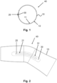
- a cross section through a sleeve-shaped bandage 40 is shown, which has a base body made of a sheet material 10.
- the sheet material 10 is made of an elastic material, in particular an elastic textile or a foam, and in the embodiment shown has a closed cross section, so that the bandage 40 has a sleeve-shaped shape overall.
- the elastic sheet material 10 has an inner side facing the user or patient, which is referred to as the back side 11, and a outer side or front side 12 facing away from the patient, which is opposite the rear side 11.
- a limiting element 30 which serves to limit the elasticity of the surface material 10.
- the limiting element 30 locally reduces the extensibility of the surface material 10 in the area of the functional element 20, possibly reducing it to zero, so that when the elastic surface material 10 is stressed by a movement or by the bandage 40 being applied to the patient, no or almost no stretching occurs in the area of the functional element 20, but the extensibility in the other areas of the bandage 40 is not impaired.
- the application of shear stresses in the region of the connection between the functional element 20 and the surface material 10 is prevented or at least significantly reduced, so that the functional element 20 can be securely and permanently attached to the outside or front side 12 of the surface material 10.
- FIG. 2 shows a design and use of the elastic sheet material 10 as a bandage 40 that is intended to span a knee joint.
- the bandage 40 is sleeve-shaped and has a pre-flexion in order to prevent excessive stretching in the kneecap area, i.e. on the front of the knee, and excessive compression in the popliteal area, i.e. on the back of the knee.
- the lower leg area which in the Figure 2 shown on the left, has a cross-section that tapers towards the distal end, the thigh area widens towards the proximal end.
- a functional element 20 in the form of a spring, rail or stiffening element is applied, in particular welded or glued on.
- the functional element 20 can also be designed as a channel or component holder for receiving a rail, a spring or a joint rail, it can also be designed as a hook, holder for sensors, cables, as the cable itself, as a conductor, as a clip element, buckle, zipper, protector or as a sensor.
- improved guidance of the joint in the applied state is achieved.
- the limiting element 30, which is shown with a broken line, is arranged on the inside or back 11 of the sheet material.
- the limiting element 30 is preferably flexible, but not elastic, and can be designed as a film, adhesive layer and elastic textile or similar.
- the limiting element 30 can be integrally connected to the sheet material, for example glued or welded on, or integrated within the sheet material 10, for example cast, foamed or laminated in.
- the functional element 20 has an outer contour 21 which lies within an outer contour 31 of the limiting element 30, so that no elastic sheet material 10 exerts an elastic or increased elastic stretch in the area in which the functional element 20 is attached to the outside or front 12 of the sheet material 10.
- the outer contour 31 of the limiting element 30 projects beyond the outer contour 21 of the functional element 20 on all sides to ensure that no unwanted shear stress occurs at any point.
- Figure 3 shows an elastic sheet material 10 as the base material.
- Connecting devices 50 in the form of Velcro areas, snap fasteners, buckles, loops or the like are arranged or designed on two opposite side edges of the sheet material 10 in order to connect the end areas to one another and to form a closed cross-section, for example in order to design the sheet material 10 into a bandage 40 with a closed cross-section that is easy to put on and take off again and is adjustable in terms of its diameter or circumference.
- the functional element 20 is applied directly to the limiting element 30, for example glued, printed or welded on, with the limiting element 30 being attached to the front side 12 of the sheet material 10.
- the limiting element 30 is partially embedded in the material of the sheet material 10 and protrudes slightly beyond the front side 12.
- the limiting element 30 can be completely embedded in the sheet material 10 be integrated and flush with the front side 12, so that a common plane is formed between the front side 12 and the outside of the limiting element 30, on which the functional element 20 is then applied, in particular glued or welded.
- the outer circumference of the limiting element 30 is larger than that of the functional element 20 and the projection of the functional element 20 lies within the projection of the limiting element 30.
- the limiting element 30 is embedded within the surface material and the functional element 20 is arranged and fastened on the surface material 10 on the front side 12.
- the limiting element 30 is also larger than the functional element 20, the outer contour 21 of the functional element 20 lies within the outer contour 31 of the limiting element 30.
- Figure 5 shows a further variant in which, instead of a single limiting element 30 on the back 11, a plurality of limiting elements 30, here five, are arranged, which are positioned in strip form and connected to the surface material 10.
- a plurality of limiting elements 30, here five are arranged, which are positioned in strip form and connected to the surface material 10.
- Such an arrangement is particularly useful when tensile forces are only to be expected in the longitudinal extension of the limiting elements 30 and the functional element 20 and/or the limiting element 30 extends predominantly in the longitudinal extension.
- a grid-like arrangement of strip-shaped limiting elements 30 is also possible.
- Limiting elements 30 are attached to the back 11 of the surface material 10 in the manner in which they are used in connection with the limiting element 30 of the Figure 3 described. In the arrangement of the limiting elements 30 that protrudes slightly inwards, as shown, they can also be designed to be flush with the rear side.
- Figure 6 shows a variant of the Figure 2 with two limiting elements 30, which are arranged at the distal and proximal end regions of the functional element 20 on the rear side 11 or within the sheet material 10, as indicated by the broken lines.
- the functional element 30 for example a spring or a splint that is elastic in this region or also a joint splint, is not connected to the front side 12 or outside of the sheet material 10 in the region that is not covered by the limiting elements 30, in order to thus enable a relative movement between the functional element 20 and the base body 10 of the bandage 40 in this region.
- the functional element 20 protrudes in some regions beyond the outer contour 31 of the limiting element.
- FIG. 7 A further variant of the invention is described in Figure 7 shown, in which the limiting element 30 is arranged on the back 11 of the surface material 10.
- the limiting element 30 has penetration elements 32 in the form of pins that penetrate the surface material 10 and protrude beyond the front 12.
- the penetration elements 32 can have projections, fastening elements, receptacles for clips or similar form-fitting elements or simply plate-like or mushroom-like widenings in order to achieve a form-fitting fastening via the penetration elements 32 in addition to a material-locking fastening of the limiting element 30 on the back 11.
- the penetration elements 32 serve to fasten the functional element 20 or to support the fastening to the surface material 10.
- the fastening can be carried out in a material-locking manner on the front side 12 of the surface material 10 alone or in conjunction with a form-fitting or material-locking connection with the penetration elements 32.
- Figure 8 shows a further variant of the invention, in which the limiting element 30 is integrated within the surface material 10 and completely penetrates it in the area of the functional element 20.
- the limiting element 30 can be applied as an initially liquid adhesive in a defined area to a textile base body and penetrate the textile.
- the functional element 20, e.g. a stiffening element can be fixed to the surface material 10 via the adhesive of the limiting element 30.
- the adhesive stiffens the textile and prevents movement in the area in which the adhesive hardens.
- the limiting element 30 can be flush with the surface material 10 on the front side 12 or protrude beyond it, as is the case in the Figure 8 is shown. On the inner side 11, the limiting element 30 preferably ends flush with the surface material 10.
- the limiting element 30 is similarly flexible as the sheet material 10, but has a significantly reduced extensibility.
Landscapes
- Health & Medical Sciences (AREA)
- Engineering & Computer Science (AREA)
- Biomedical Technology (AREA)
- Heart & Thoracic Surgery (AREA)
- Vascular Medicine (AREA)
- Life Sciences & Earth Sciences (AREA)
- Animal Behavior & Ethology (AREA)
- General Health & Medical Sciences (AREA)
- Public Health (AREA)
- Veterinary Medicine (AREA)
- Cardiology (AREA)
- Oral & Maxillofacial Surgery (AREA)
- Transplantation (AREA)
- Nursing (AREA)
- Orthopedic Medicine & Surgery (AREA)
- Orthopedics, Nursing, And Contraception (AREA)
- Materials For Medical Uses (AREA)
- Professional, Industrial, Or Sporting Protective Garments (AREA)
Description
- Die Erfindung betrifft ein elastisches Flächenmaterial mit einer Vorderseite und einer der Vorderseite gegenüberliegenden Rückseite und zumindest einem auf der Vorderseite angeordneten Funktionselement, das mit dem Flächenmaterial verbunden ist. Die Erfindung betrifft ebenfalls eine Bandage auf einem solchen Flächenmaterial sowie ein Verfahren zum Herstellen eines solchen Flächenmaterials. Ein solches Flächenmaterial wird insbesondere als Ausgangswerkstoff zum Herstellen von orthopädietechnischen Geräten oder Orthesen, insbesondere zum Herstellen von Manschetten oder Bandagen verwendet.
- Manschetten, Bandagen oder Orthesen weisen in der Regel einen elastischen Grundkörper auf, der um die Gliedmaße oder einen Gelenkbereich herum angelegt werden kann. An dem Grundkörper kann ein Stabilisierungselement angeordnet sein, beispielsweise eine Metallschiene oder eine Kunststoffschiene. Bandagen oder Manschetten werden zur Unterstützung oder Stabilisierung der Gelenkfunktion oder der Muskulatur und Bändern angelegt. Dazu wird die Bandage über das zu schützende Gelenk oder die zu unterstützende Muskulatur gezogen oder darum gewickelt und fixiert. Bandagen lassen, im Gegensatz zu Immobilisationsorthesen, eine Bewegung der durch das Gelenk verbundenen Gliedmaßen relativ zueinander zu. Dazu weisen die Bandagen einen Grundkörper auf, der aus einem flexiblen Material besteht, beispielsweise einem Schaumstoff oder einem Textil. Zur Unterstützung der Stabilisationswirkung sind an dem Grundkörper Stabilisierungselemente angeordnet, die eine gegenüber dem Grundkörper erhöhte Festigkeit und Steifigkeit aufweisen, sodass neben einem Schutz gegen mechanische Einwirkung eine erhöhte Bewegungseinschränkung bewirkt wird.
- Aus der
US 2008/0039757 A1 ist eine flexible Bandage mit einem Rahmen mit einer Oberfläche zum Anlegen an einen Körperbereich bekannt, wobei der Rahmen eine Vielzahl an Öffnungen aufweist. An dem Rahmen selbst kann ein Gewebe oder ein Schaumstoff angebracht sein, beispielsweise durch Verschweißen, Verkleben oder durch Vernähen. - Die
EP 876 130 B1 - Die
US 6,024,712 A beschreibt eine Sprunggelenkorthese mit einem inneren Textilteil, das sich zumindest teilweise um ein Sprunggelenk erstreckt. Eine Außenstütze ist mit dem Textil über ein Spritzgussverfahren verbunden und stellt eine zusätzliche Abstützung des Gelenkes gegen unbeabsichtigte Bewegungen dar. - Die
CA 2,398,059 A1 beschreibt eine orthopädische Stütze mit einem flexiblen Innenteil und einer Außenstütze, die direkt auf das flexible Innenteil aufgeformt ist. - Die
WO 2013/072064 A1 beschreibt eine orthopädietechnische Manschette zur Anlage an einem Körper mit einem flexiblen Grundkörper mit zumindest einem daran angeordneten Stabilisierungselement aus Kunststoff. Das Stabilisierungselement weist Bereiche mit einem gegenüber dem übrigen Querschnitt verringerten Querschnitt auf, in denen das Stabilisierungselement auf dem Grundkörper aufgeklebt und/oder stoffschlüssig mit dem Grundkörper verbunden ist. Das Stabilisierungselement kann auf einem flexiblen Trägermaterial aufgebracht sein, insbesondere aufgespritzt oder hinterspritzt sein. Das Trägermaterial bildet dann die Bereiche aus, die stoffschlüssig mit dem Grundkörper verbunden sind. - Bei der Verbindung von Polymeren mit elastischen, insbesondere textilen Flächenmaterialien wird häufig das Spritzgussverfahren angewendet, bei dem die Polymere tief in das textile Gewebe eindringen. Problematisch bei diesem Herstellverfahren ist die mangelnde Flexibilität, da für jede Ausgestaltung ein neues Werkzeug aufwendig hergestellt werden muss.
- Die
EP 2 090 273 A2 beschreibt eine Bandage aus einem Gestrick, die ein Stabilisierungselement für ein Gelenk aufweisen kann. Dieses kann beispielsweise auf der Außenseite der Bandage angeordnet und dann über eine Schnellverschlussvorrichtung fixiert werden. Daneben ist es auch möglich, dass das Stabilisierungselement in eine in der Bandage ausgebildeten Tasche angeordnet wird. - Die
US 2013/0046394 A1 beschreibt einen Gel-Liner für eine Prothese. Auf der Linerinnenseite ist eine Mehrzahl von Elektroden zur Abnahme myoelektrischer Signale angeordnet. Auf der Außenseite des Liners ist ein Prothesenschaft angeordnet, dass den Liner umgibt - Aufgabe der vorliegenden Erfindung ist es daher, ein Flächenmaterial, eine Bandage sowie ein Verfahren zum Herstellen eines Flächenmaterials bereitzustellen, die eine dauerhafte und preisgünstige Verbindung eines Funktionselementes an dem Flächenmaterial bei einer hohen Individualisierungsrate ermöglichen.
- Erfindungsgemäß wird diese Aufgabe durch ein Flächenmaterial mit den Merkmalen des Hauptanspruches, eine daraus hergestellte Bandage sowie ein Verfahren mit den Merkmalen des nebengeordneten Anspruchs gelöst. Vorteilhafte Ausgestaltungen und Weiterbildungen der Erfindung sind in den jeweiligen Unteransprüchen, der Beschreibung sowie den Figuren offenbart.
- Das erfindungsgemäße elastische Flächenmaterial mit einer Vorderseite und einer der Vorderseite gegenüberliegenden Rückseite und zumindest einem auf der Vorderseite angeordneten Funktionselement, das mit dem Flächenmaterial verbunden ist, sieht vor, dass auf der Rückseite des Flächenmaterials dem Funktionselement gegenüberliegend und/oder auf der Vorderseite unterhalb des Funktionselementes und/oder innerhalb des Flächenmaterials ein Begrenzungselement zur Begrenzung der Elastizität des Flächenmaterials, insbesondere lokal in dem Bereich des Funktionselementes angeordnet ist. Die Rückseite eines elastischen Flächenmaterials wird insbesondere zur Auflage oder Anlage an einer Hautoberfläche eingesetzt, während ein Funktionselement in der Regel eine rigide oder abstehende Struktur aufweist, die besser an der Außenseite, also auf der dem Körper abgewandten Seite des Flächenmaterials, angeordnet ist. Die Anordnung eines Begrenzungselementes, das die Elastizität des Flächenmaterials begrenzt oder aufhebt, zumindest in der Ebene der Vorderseite und Rückseite hat den Vorteil, dass auch bei einem weniger tiefen Eindringen des Materials des Funktionselementes in die Struktur des elastischen Flächenmaterials keine Spannung und keine Relativbewegung beim Dehnen und wieder Zusammenziehen des Textils beim radialen oder longitudinalen Aufweiten des Flächenmaterials entsteht. Ein Verringern der Dicke des Flächenmaterials, also ein Aufeinanderzubewegen der Rückseite auf die Vorderseite, ist dabei unschädlich und muss durch das Begrenzungselement nicht verhindert werden. Eine Begrenzung der Elastizität vorwiegend in eine Richtung kann durch spezielle Ausgestaltungen des Begrenzungselementes erreicht werden, beispielsweise durch ein flexibles Gewebe, das in einer Richtung zugstarr und in der senkrecht dazu orientierten Richtung elastisch ist. Damit wird eine ausreichende Begrenzung insbesondere bei Funktionselementen erzielt, die sich überwiegend nur in eine Richtung erstrecken. Das Begrenzungselement verhindert oder vermindert ein Ausdehnen und Zusammenziehen des Flächenmaterials als Träger für das Funktionselement und verhindert oder reduziert somit eine Relativbewegung zwischen dem Funktionselement und dem Flächenmaterial, da keine oder verminderte Spannungen bei einer Dehnung des Flächenmaterials auf die Bindungsflächen oder den Anbindungsbereich des Funktionselementes mit dem Flächenmaterial übertragen werden. Dadurch wird verhindert, dass sich die physikalische Verbindung zwischen dem Funktionselement und dem Flächenmaterial lockert oder aufhebt, sodass die Dauerfestigkeit der Anbindung des Funktionselementes an dem Flächenmaterial beibehalten wird. Es hat sich überraschend gezeigt, dass selbst bei einer Versteifung nur auf einer Seite des Flächenmaterials, also auf der Vorderseite, innerhalb des Flächenmaterials oder auf der Rückseite, sich die Dauerfestigkeit der Verbindung des Funktionselementes mit dem Flächenmaterial wesentlich erhöht hat, nachdem das Flächenmaterial durch das Aufbringen oder Anordnen des Begrenzungselementes vorher partiell versteift wurde. Die partielle Rigidität des Flächenmaterials hat zudem den Vorteil, dass die Elastizität des Endproduktes in seiner Gesamtheit nur unwesentlich und nur in den Teilbereichen, in denen das Funktionselement angeordnet ist, eingeschränkt wird. Da die Funktionselemente in der Regel ebenfalls im Bereich der Anbindung an das elastische Flächenmaterial rigide ausgestaltet sind, ergibt sich keine merkliche Einschränkung in dem Tragekomfort des Flächenmaterials, wenn dieses zu einer orthopädietechnischen Einrichtung, beispielsweise einer Bandage oder einer Manschette, verarbeitet wird. Das Begrenzungselement kann sowohl auf der dem Funktionselement gegenüberliegenden Seite angeordnet sein als auch eine Zwischenschicht zwischen Funktionselement und Flächenmaterial bilden.
- Das Flächenmaterial ist bevorzugt als Textil ausgebildet, beispielsweise ein Gestrick, Gelege oder Gewirk. Die Ausgestaltung als Abstandsgewirk ist ebenfalls vorgesehen. Alternativ kann das Flächenmaterial als Schaumstoff ausgebildet sein oder Schaumstoffanteile enthalten. Als Flächenmaterial wird ein Material angesehen, das eine überwiegend zweidimensionale Ausdehnung aufweist, also eine große Fläche bei einer geringen Materialstärke aufweist.
- Das Begrenzungselement weist in einer Weiterbildung der Erfindung eine Außenkontur auf, die der Außenkontur des Funktionselementes entspricht oder die Außenkontur des Funktionselementes zumindest teilweise, bevorzugt vollständig einschließt. Entspricht die Außenkontur des Begrenzungselementes der Außenkontur des Funktionselementes, wird nur ein minimaler Bereich des Flächenmaterials versteift, wodurch das übrige Elastizitätsverhalten des Flächenmaterials nicht beeinträchtigt wird. Bei einem vergrößerten Flächenbereich des Begrenzungselementes im Vergleich zur Außenkontur des Funktionselementes wird eine größere Fläche des Flächenmaterials versteift, was einerseits die Positionierung des Funktionselementes erleichtert und andererseits Spannungen in dem Randbereich des Flächenmaterials am Übergang zu dem Funktionselement verhindert und dadurch eine erhöhte Dauerhaltbarkeit bereitstellt. Alternativ kann die Außenkontur des Begrenzungselementes auch nur die Bereiche des Funktionselemtens abdecken, die rigide ausgebildet sind. Andere Bereiche des Funktionselementes wie etwa Federn, die selbst eine ausreichende Elastizität ausbilden, können der Bewegung des elastischen Flächenmaterials folgen und lösen sich nicht so schnell ab, sodass hier eine Begrenzung der Elastizität des Flächenmaterials nicht zwingend erforderlich ist.
- Das Begrenzungselement ist bevorzugt stoffschlüssig mit dem Flächenmaterial verbunden, beispielsweise verschweißt oder verklebt.
- Das Begrenzungselement kann als Folie auf das Flächenmaterial aufgeklebt oder aufgeschweißt, bevorzugt vollflächig aufgeklebt oder verschweißt werden. Ebenfalls ist es möglich, dass das Begrenzungselement durch eine Klebstoffschicht oder durch eine Vielzahl von Klebstoffstreifen oder Klebstoffpunkten oder ein Klebstoffgitter ausgebildet wird, das auf dem Flächenmaterial aufgebracht wird, so dass es an der Oberfläche haftet und/oder in das Flächenmaterial eindringt. Alternativ kann das Begrenzungselement als ein unelastisches, aber flexibles Textil, ein Durchdringungselement, das das Flächenmaterial durchdringt und einen Vorsprung auf der gegenüberliegenden, insbesondere der Vorderseite ausbildet, als ein leitfähiges Textil oder Band oder Kabel, beispielsweise eine metallische Fadenkomponente aufweisend, ausgebildet sein, um zwar eine ausreichende Flexibilität zu ermöglichen, die Elastizität jedoch in dem Teilbereich, in dem das Begrenzungselement aufgebracht ist, zumindest zu vermindern oder aufzuheben. Das Begrenzungselement kann auch als Sensor, beispielsweise kapazitiver Sensor ausgebildet sein, um über die Begrenzungsfunktion bezüglich der Elastizität hinaus einen funktionalen Beitrag zur Ausgestaltung einer orthopädietechnischen Komponente zu liefern.
- Eine Weiterbildung der Erfindung sieht vor, dass mehrere Begrenzungselemente getrennt voneinander auf dem Flächenmaterial angeordnet sind, um die Elastizität und Flexibilität des Gesamtflächenmaterials nicht oder nur möglichst wenig einzuschränken. Die Begrenzungselemente können beispielsweise in einer Längserstreckung hintereinander, getrennt voneinander auf dem Flächenmaterial aufgebracht und daran festgelegt sein. Ebenfalls ist es möglich, bei einer hülsenartigen Ausgestaltung des fertigen Produktes über den Umfang verteilt, in Längsrichtung orientierte Begrenzungselemente vorzusehen, die ein radiales Aufweiten in den Zwischenbereichen zwischen den Begrenzungselementen ermöglichen, eine Längung in Längserstreckung jedoch zumindest bereichsweise verhindern.
- Die Begrenzungselemente oder das Begrenzungselement sind bevorzugt flexibel ausgebildet, um das Flächenmaterial an unterschiedliche Oberflächen, insbesondere Körperoberflächen, anpassen zu können. Das heißt, dass das Begrenzungselement biegsam ist, jedoch keine oder nur eine verminderte Längenveränderung in der Ebene zulässt.
- Eine Weiterbildung der Erfindung sieht vor, dass das Funktionselement auf dem Flächentextil aufgedruckt oder mittels eines additiven Herstellverfahrens auf dem Flächenmaterial aufgebracht ist, also in einem schichtweisen Auftragsprozess oder additiven Herstellverfahren auf dem Flächentextil aufgebracht und dort formschlüssig und/oder stoffschlüssig verbunden wird. Das Funktionselement kann beispielsweise als Elastomer oder aus einem Elastomer ausgebildet und insbesondere in einem additiven Herstellverfahren auf dem Textil aufgebracht werden. Über additive Herstellverfahren, z.B. den sogenannten 3D-Druck, beispielsweise mit einem SLA-Drucker oder FDM-Drucker, ist es möglich, individuelle Produkte herzustellen, indem die Funktionselemente an den jeweiligen Nutzer angepasst auf das Flächenmaterial aufgebracht, z.B. aufgedruckt werden und dieses anschließend zu einem Endprodukt verarbeitet wird. Auch ist es möglich, das Flächenmaterial zunächst in eine Grundform zu bringen, beispielsweise als Kniemanschette, Ellenbogenmanschette oder Wadenmanschette und anschließend auf die bereits vorgeformte Grundform das jeweils gewünschte Funktionselement aufzubringen oder aufzudrucken. Das Aufbringen oder Aufdrucken kann beispielsweise nach dem Anpassen der Bandage an den jeweiligen Körper erfolgen, sodass die Positionierung der Funktionselemente auf dem Flächentextil hochgenau und individuell erfolgen kann.
- Das Funktionselement kann als Feder, Schiene, Versteifungselement, Bauteilaufnahme, Kanal, Haken, Sensorhalter, Kabelführung, Kabel, Leiter, Klipselement, Schnalle, Reißverschluss, Protektor, Polster, Luftpolster, Elastomerelement und/oder Sensor ausgebildet sein.
- Die Erfindung betrifft ebenfalls eine Bandage aus einem Flächenmaterial wie es oben beschrieben worden ist. Eine Weiterbildung der Bandage sieht vor, dass diese hülsenartig mit einem geschlossenen Querschnitt oder aus einem flächigen Grundkörper mit Verbindungseinrichtungen ausgebildet ist, die an einander gegenüberliegenden Endbereichen angeordnet sind. Sofern die Bandage einen geschlossenen Querschnitt aufweist, kann dieser unterbrochen ausgebildet sein, beispielsweise um Ausnehmungen für Vorsprünge zu bilden. Bei einer Ausgestaltung der Bandage als Kniebandage kann eine Ausnehmung im Bereich der Patella und/oder Kniekehle ausgebildet sein, bei einer Ellenbogenbandage kann eine Ausnehmung beispielsweise im Bereich der Ellenbeuge angeordnet sein. Mit einem geschlossenen Querschnitt kann die Bandage über ein Körperglied gezogen werden. Alternativ ist es möglich, die Bandage mit einem offenen Querschnitt auszubilden und nach dem Anlegen an den Körper zu schließen und in der jeweiligen gewünschten Position und in der gewünschten Spannung zu fixieren. Dazu sind an einander gegenüberliegenden Kanten oder Endbereichen des Flächenmaterials Verbindungseinrichtungen wie Klettverschlüsse, Schlaufen oder Schnallen angeordnet, um den zunächst offenen Querschnitt des Zuschnitts zu schließen.
- Das Verfahren zum Herstellen eines oben beschriebenen Flächenmaterials sieht vor, dass das Funktionselement mit dem Flächenmaterial verbunden wird und zumindest ein Begrenzungselement zwischen dem Funktionselement und dem Flächenmaterial und/oder innerhalb des Flächenelementes insbesondere im Bereich des Funktionselementes und/oder auf der dem Funktionselement gegenüberliegenden Seite des Flächenmaterials angeordnet und verbunden wird und durch das Begrenzungselement die Elastizität des Flächenmaterials zumindest verringert wird. Das Verbinden des Begrenzungselementes mit dem Flächenmaterial erfolgt dabei bevorzugt vor dem Verbinden des Funktionselementes mit dem Flächenmaterial.
- Das Funktionselement kann in einem additiven Herstellverfahren, z.B. 3D-Druckverfahren, auf das Flächenmaterial oder das Begrenzungselement aufgebracht oder aufgedruckt werden. Bevorzugt wird das Begrenzungselement vollflächig mit dem Flächenmaterial verbunden, beispielsweise vollflächig verschweißt oder verklebt, um eine im Anbindungsbereich des Funktionselementes auftretende Lockerung und Relativbewegung des Flächenmaterials zu verhindern.
- Bevorzugt wird das Funktionselement innerhalb der Außenkontur des Begrenzungselementes angeordnet, um an den Übergangsstellen des Funktionselementes zu dem Flächenelement keine Relativbewegungen zwischen dem Flächenmaterial und dem Funktionselement zu ermöglichen und dadurch die Dauerhaltbarkeit des befestigten Funktionselementes zu erhöhen.
- Das Begrenzungselement wird bevorzugt stoffschlüssig mit dem Flächenmaterial verbunden, um eine dauerhafte Elastizitätsbegrenzung zu erreichen.
- Nachfolgend wird die Erfindung anhand der Figuren näher erläutert. Es zeigen:
- Figur 1
- eine Schnittdarstellung einer Bandage;
- Figur 2
- eine Seitenansicht einer Kniebandage;
- Figur 3
- eine Schnittdarstellung und eine Draufsicht auf ein Flächenmaterial;
- Figur 4
- eine Variante der
Figur 3 ; - Figur 5
- eine Variante der
Figur 3 ; - Figur 6
- eine Variante der
Figur 2 ; - Figur 7
- eine Variante der
Figur 5 ; sowie - Figur 8
- eine Schnittdarstellung durch ein Flächenmaterial
- In der
Figur 1 ist ein Querschnitt durch eine hülsenförmige Bandage 40 gezeigt, die einen Grundkörper aus einem Flächenmaterial 10 aufweist. Das Flächenmaterial 10 ist aus einem elastischen Werkstoff, insbesondere einem elastischen Textil oder einem Schaumstoff hergestellt und weist in dem dargestellten Ausführungsbeispiel einen geschlossenen Querschnitt auf, so dass die Bandage 40 insgesamt eine hülsenförmige Form aufweist. Im Verlauf der Längserstreckung der Bandage 40 können sich der Querschnitt und die Form des Grundkörpers verändern. Das elastische Flächenmaterial 10 weist eine dem Nutzer oder Patienten zugewandte Innenseite, die als Rückseite 11 bezeichnet wird, und eine im angelegten Zustand der Bandage 40 dem Patienten abgewandte Außenseite oder Vorderseite 12 auf, die der Rückseite 11 gegenüberliegt. Auf der Vorderseite 12 des Grundkörpers ist ein Funktionselement 20 angeordnet, das mit dem Flächenmaterial 10 des Grundkörpers verbunden ist. Auf der Rückseite 11 dem Funktionselement 20 gegenüberliegend ist ein Begrenzungselement 30 angeordnet, das zur Begrenzung der Elastizität des Flächenmaterials 10 dient. Durch das Begrenzungselement 30 wird die Dehnbarkeit des Flächenmaterials 10 im Bereich des Funktionselementes 20 lokal verringert, gegebenenfalls auf null verringert, so dass bei einer Beanspruchung des elastischen Flächenmaterials 10 durch eine Bewegung oder durch das Anlegen der Bandage 40 an den Patienten keine oder nahezu keine Dehnung in dem Bereich des Funktionselementes 20 auftritt, die Dehnbarkeit in den übrigen Bereichen der Bandage 40 jedoch nicht beeinträchtigt wird. Dadurch wird das Aufbringen von Scherspannungen im Bereich der Verbindung zwischen dem Funktionselement 20 und dem Flächenmaterial 10 verhindert oder zumindest signifikant vermindert, so dass das Funktionselement 20 sicher und dauerhaft an der Außenseite oder Vorderseite12 des Flächenmaterials 10 befestigt werden kann. -
Figur 2 zeigt eine Ausgestaltung und Verwendung des elastischen Flächenmaterials 10 als eine Bandage 40, die ein Kniegelenk überspannen soll. Die Bandage 40 ist hülsenförmig aufgebaut und weist eine Vorflexion auf, um eine übermäßige Dehnung im Kniescheibenbereich, also auf der Vorderseite des Knies, und eine übermäßige Stauchung im Kniekehlenbereich, also auf der Rückseite des Knies, zu verhindern. Der Unterschenkelbereich, der in derFigur 2 links dargestellt ist, weist einen sich zum distalen Ende hin verjüngenden Querschnitt auf, der Oberschenkelbereich erweitert sich zum proximalen Ende hin. Auf der Außenseite ist, das Kniegelenk überspannend, ein Funktionselement 20 in Gestalt einer Feder, Schiene oder eines Versteifungselementes aufgebracht, insbesondere aufgeschweißt oder aufgeklebt. Das Funktionselement 20 kann auch als Kanal oder Bauteilaufnahme zur Aufnahme einer Schiene, einer Feder oder einer Gelenkschiene ausgebildet sein, ebenfalls kann es als Haken, Halter für Sensoren, Kabel, als Kabel selbst, als Leiter, als Klipselement, Schnalle, Reißverschluss, Protektor oder als Sensor ausgebildet sein. Im dargestellten Ausführungsbeispiel mit dem Funktionselement 20 als Schiene oder Versteifungselement wird eine verbesserte Führung des Gelenkes im angelegten Zustand erreicht. Auf der Innenseite oder Rückseite 11 des Flächenmaterials ist das Begrenzungselement 30 angeordnet, das mit einer durchbrochenen Linie dargestellt ist. Das Begrenzungselement 30 ist bevorzugt flexibel, jedoch nicht elastisch und kann als Folie, Klebstoffschicht und elastisches Textil oder Ähnliches ausgebildet sein. Es besteht auch die Möglichkeit, dass mehrere Begrenzungselemente 30 übereinander angeordnet sind, um die Begrenzungswirkung zu verstärken. Das Begrenzungselement 30 kann stoffschlüssig mit dem Flächenmaterial verbunden sein, beispielsweise aufgeklebt oder aufgeschweißt oder aber innerhalb des Flächenmaterials 10 integriert sein, beispielsweise eingegossen, eingeschäumt oder einlaminiert. Das Funktionselement 20 weist eine Außenkontur 21 auf, die innerhalb einer Außenkontur 31 des Begrenzungselementes 30 liegt, so dass kein elastisches Flächenmaterial 10 in dem Bereich, in dem das Funktionselement 20 auf der Außenseite oder Vorderseite 12 des Flächenmaterials 10 angebracht ist, eine elastische oder eine verstärkt elastische Dehnung ausübt. In dem dargestellten Ausführungsbeispiel steht die Außenkontur 31 des Begrenzungselementes 30 allseitig über die Außenkontur 21 des Funktionselementes 20 über, um sicherzustellen, dass an keiner Stelle eine ungewollte Scherspannung auftritt. -
Figur 3 zeigt ein elastisches Flächenmaterial 10 als Grundmaterial. An zwei einander gegenüberliegenden Seitenkanten des Flächenmaterials 10 sind Verbindungseinrichtungen 50 in Gestalt von Klettverschlussbereichen, Druckknöpfen, Schnallen, Schlaufen oder dergleichen angeordnet oder ausgebildet, um die Endbereiche miteinander zu verbinden und einen geschlossenen Querschnitt auszubilden, um beispielsweise das Flächenmaterial 10 zu einer Bandage 40 mit einem geschlossenen Querschnitt auszugestalten, die leicht angelegt und wieder abgelegt und hinsichtlich ihres Durchmessers oder Umfanges anpassbar ist. In der linken Schnittdarstellung ist zu erkennen, dass das Funktionselement 20 unmittelbar auf dem Begrenzungselement 30 aufgebracht ist, beispielsweise aufgeklebt, aufgedruckt oder aufgeschweißt, wobei das Begrenzungselement 30 auf der Vorderseite 12 des Flächenmaterials 10 befestigt ist. Das Begrenzungselement 30 ist teilweise in das Material des Flächenmaterials 10 eingebettet und steht leicht über die Vorderseite 12 hinaus. Alternativ kann das Begrenzungselement 30 vollständig in dem Flächenmaterial 10 integriert sein und bündig mit der Vorderseite 12 abschließen, so dass eine gemeinsame Ebene zwischen der Vorderseite 12 und der Außenseite des Begrenzungselementes 30 gebildet wird, auf der dann das Funktionselement 20 aufgebracht, insbesondere aufgeklebt oder aufgeschweißt wird. In der rechten Darstellung derFigur 3 ist zu erkennen, dass der Außenumfang des Begrenzungselementes 30 größer als der des Funktionselementes 20 ist und die Projektion des Funktionselementes 20 innerhalb der Projektion des Begrenzungselementes 30 liegt. - In der
Figur 4 ist eine Variante des Flächenmaterials 10 gezeigt. In der Schnittdarstellung ist zu erkennen, dass das Begrenzungselement 30 innerhalb des Flächenmaterials eingebettet und das Funktionselement 20 auf dem Flächenmaterial 10 auf der Vorderseite 12 angeordnet und befestigt ist. Durch die Anordnung des Begrenzungselementes 30 innerhalb des Flächenmaterials 10 hinter dem Funktionselement 20 wird beim Aufbringen einer Zugkraft über das Flächenmaterial 10 eine Weiterleitung von Scherkräften an der Außenseite oder Vorderseite 12 verhindert und eine Scherspannung im Bereich der Befestigung des Funktionselementes 20 verhindert oder zumindest vermindert. Das Begrenzungselement 30 ist hier ebenfalls großflächiger als das Funktionselement 20, die Außenkontur 21 des Funktionselementes 20 liegt innerhalb der Außenkontur 31 des Begrenzungselementes 30. -
Figur 5 zeigt eine weitere Variante, bei der statt eines einzelnen Begrenzungselementes 30 auf der Rückseite 11 eine Vielzahl, hier fünf Begrenzungselemente 30 angeordnet sind, die streifenförmig positioniert und mit dem Flächenmaterial 10 verbunden sind. Eine solche Anordnung ist insbesondere dann sinnvoll, wenn Zugkräfte nur in Längserstreckung der Begrenzungselemente 30 und des Funktionselementes 20 zu erwarten sind und/oder sich das Begrenzungselement 30 überwiegend in Längserstreckung erstreckt. Eine gitterförmige Anordnung von streifenförmigen Begrenzungselementen 30 ist ebenfalls möglich. Begrenzungselemente 30 sind auf der Rückseite 11 des Flächenmaterials 10 in der Art und Weise befestigt, wie sie im Zusammenhang mit dem Begrenzungselement 30 derFigur 3 beschrieben wurden. In der, wie dargestellt, leicht nach Innen überstehenden Anordnung der Begrenzungselemente 30 können diese auch bündig mit der Rückseite abschließend ausgebildet sein. -
Figur 6 zeigt eine Variante derFigur 2 mit zwei Begrenzungselementen 30, die an den distalen und proximalen Endbereichen des Funktionselementes 20 auf der Rückseite 11 oder innerhalb des Flächenmaterials 10 angeordnet sind, wie durch die unterbrochenen Linien angedeutet ist. Im Bereich der natürlichen Gelenkachse, hier Kniegelenksachse, sind keine Begrenzungselemente 30 angeordnet, um eine freie Beweglichkeit in diesem Bereich zuzulassen. Es besteht die Möglichkeit, dass das Funktionselement 30, beispielsweise eine Feder oder eine in diesem Bereich elastische Schiene oder auch eine Gelenkschiene, in dem Bereich, der nicht von den Begrenzungselementen 30 abgedeckt ist, nicht mit der Vorderseite 12 oder Außenseite des Flächenmaterials 10 verbunden ist, um so eine Relativbewegung zwischen dem Funktionselement 20 und dem Grundkörper 10 der Bandage 40 in diesem Bereich zu ermöglichen. Das Funktionselement 20 ragt in diesem Ausführungsbeispiel bereichsweise über die Außenkontur 31 des Begrenzungselementes hinaus. - Eine weitere Variante der Erfindung ist in der
Figur 7 gezeigt, bei der auf der Rückseite 11 des Flächenmaterials 10 das Begrenzungselement 30 angeordnet ist. Das Begrenzungselement 30 weist Durchdringungselemente 32 in Gestalt von Stiften auf, die das Flächenmaterial 10 durchdringen und über die Vorderseite 12 hinausragen. Im Bereich der Durchdringung können die Durchdringungselemente 32 Vorsprünge, Befestigungselemente, Aufnahmen für Klipse oder ähnliche Formschlusselemente oder einfach nur tellerartige oder pilzartige Verbreiterungen aufweisen, um zusätzlich zu einer stoffschlüssigen Befestigung des Begrenzungselementes 30 auf der Rückseite 11 eine formschlüssige Befestigung über die Durchdringungselemente 32 zu erreichen. Grundsätzlich ist es auch möglich, auf eine stoffschlüssige Verbindung des Begrenzungselementes 30 mit dem Flächenmaterial 10 zu verzichten. Die Durchdringungselemente 32 dienen zur Befestigung des Funktionselementes 20 oder zur Unterstützung der Befestigung an dem Flächenmaterial 10. Die Befestigung kann stoffschlüssig auf der Vorderseite 12 des Flächenmaterials 10 allein oder in Verbindung mit einer formschlüssigen oder auch stoffschlüssigen Verbindung mit den Durchdringungselementen 32 erfolgen. -
Figur 8 zeigt eine weitere Variante der Erfindung, bei der das Begrenzungselement 30 innerhalb des Flächenmaterials 10 integriert ist und dieses im Bereich des Funktionselementes 20 vollständig durchdringt. Das Begrenzungselement 30 kann als zunächst flüssiger Klebstoff in einem definierten Bereich auf einen textilen Grundkörper aufgebracht werden und das Textil durchdringen. Das Funktionselement 20, z.B. ein Versteifungselement, kann über den Klebstoff des Begrenzungselementes 30 auf dem Flächenmaterial 10 fixiert werden. Der Klebstoff versteift das Textil und verhindert eine Bewegung in dem Bereich, in dem der Klebstoff aushärtet. Statt das Funktionselement 20 über den Klebstoff zu fixieren, kann es auch auf dem Begrenzungselement aufgedruckt oder über ein additives Herstellverfahren aufgebracht werden. Das Begrenzungselement 30 kann auf der Vorderseite 12 bündig mit dem Flächenmaterial 10 abschließen oder darüber hinausstehen, wie dies in derFigur 8 gezeigt ist. Auf der Innenseite 11 schließt das Begrenzungselement 30 vorzugsweise bündig mit dem Flächenmaterial 10 ab. - Bevorzugt ist das Begrenzungselement 30 ähnlich flexibel wie das Flächenmaterial 10, weist jedoch eine wesentlich verringerte Dehnbarkeit auf.
Claims (16)
- Elastisches Flächenmaterial (10) mit einer Vorderseite (12) und einer der Vorderseite (12) gegenüberliegenden Rückseite (11) und zumindest einem auf der Vorderseite (12) angeordneten Funktionselement (20), das mit dem Flächenmaterial (10) verbunden ist, dadurch gekennzeichnet, dass auf der Rückseite (11) des Flächenmaterials (10) dem Funktionselement (20) gegenüberliegend und/oder auf der Vorderseite (12) unterhalb des Funktionselementes (20) oder innerhalb des Flächenmaterials (10) unterhalb des Funktionselementes (20) ein Begrenzungselement (30) zur Begrenzung der Elastizität des Flächenmaterials (10) angeordnet ist.
- Flächenmaterial nach Anspruch 1, dadurch gekennzeichnet, dass das Begrenzungselement (30) eine Außenkontur (31) aufweist, die der Außenkontur (21) des Funktionselementes (20) entspricht oder die Außenkontur (21) des Funktionselementes (20) einschließt.
- Flächenmaterial nach Anspruch 1 oder 2, dadurch gekennzeichnet, dass das Begrenzungselement (30) stoffschlüssig mit dem Flächenmaterial (10) verbunden ist.
- Flächenmaterial nach einem der voranstehenden Ansprüche, dadurch gekennzeichnet, dass es als ein Textil ausgebildet ist.
- Flächenmaterial nach einem der voranstehenden Ansprüche, dadurch gekennzeichnet, dass das Begrenzungselement (30) als Folie, Klebstoffschicht, unelastisches Textil, Durchdringungselement (32) mit Vorsprung, leitfähiges Textil, Band, Kabel oder Sensor ausgebildet ist.
- Flächenmaterial nach einem der voranstehenden Ansprüche, dadurch gekennzeichnet, dass mehrere Begrenzungselemente (30) getrennt voneinander auf dem Flächenmaterial (10) angeordnet sind.
- Flächenmaterial nach einem der voranstehenden Ansprüche, dadurch gekennzeichnet, dass das Begrenzungselement (30) flexibel ausgebildet ist.
- Flächenmaterial nach einem der voranstehenden Ansprüche, dadurch gekennzeichnet, dass das Funktionselement (20) auf dem Flächenmaterial (10) mit einem additiven Herstellverfahren insbesondere als Elastomerelement aufgebracht ist.
- Flächenmaterial nach einem der voranstehenden Ansprüche, dadurch gekennzeichnet, dass das Funktionselement (20) als Feder, Schiene, Versteifungselement, Bauteilaufnahme, Kanal, Haken, Sensorhalter, Kabelführung, Kabel, Leiter, Klipselement, Schnalle, Reißverschluss, Protektor, Sensor, Polster oder Luftpolster ausgebildet ist.
- Bandage aus einem Flächenmaterial (10) nach einem der voranstehenden Ansprüche.
- Bandage nach Anspruch 10, dadurch gekennzeichnet, dass sie hülsenartig mit einem geschlossenen Querschnitt oder aus einem flächigen Grundkörper mit an einander gegenüberliegenden Endbereichen angeordneten Verbindungseinrichtungen (50) ausgebildet ist.
- Verfahren zum Herstellen eines Flächenmaterials (10) nach einem der Ansprüche 1 bis 8, dadurch gekennzeichnet, dass das Funktionselement (20) mit dem Flächenmaterial (10) verbunden wird und zumindest ein Begrenzungselement (30) zwischen dem Funktionselement (20) und dem Flächenmaterial (10) und/oder auf der dem Funktionselement (20) gegenüberliegenden Seite des Flächenmaterials (10) oder in das Flächenmaterials (10) eingebracht und mit dem Flächenmaterial (10) verbunden wird und dass durch das Begrenzungselement (30) die Elastizität des Flächenmaterials (10) zumindest verringert wird.
- Verfahren nach Anspruch 12, dadurch gekennzeichnet, dass das Funktionselement (20) in einem additiven Herstellverfahren auf das Flächenmaterial (10) oder das Begrenzungselement (30) aufgebracht wird.
- Verfahren nach Anspruch 12 oder 13, dadurch gekennzeichnet, dass das Begrenzungselement (30) vollflächig mit dem Flächenmaterial (10) verbunden wird.
- Verfahren nach einem der Ansprüche 12 bis 14, dadurch gekennzeichnet, dass das Funktionselement (20) innerhalb der Außenkontur (31) des Begrenzungselementes (30) angeordnet wird.
- Verfahren nach einem der Ansprüche 12 bis 15, dadurch gekennzeichnet, dass das Begrenzungselement (30) stoffschlüssig mit dem Flächenmaterial (10) verbunden wird.
Applications Claiming Priority (2)
| Application Number | Priority Date | Filing Date | Title |
|---|---|---|---|
| DE102018132640.8A DE102018132640B4 (de) | 2018-12-18 | 2018-12-18 | Elastisches Flächenmaterial, Bandage daraus und Verfahren zu dessen Herstellung |
| PCT/EP2019/083657 WO2020126501A1 (de) | 2018-12-18 | 2019-12-04 | Elastisches flächenmaterial, bandage daraus und verfahren zu dessen herstellung |
Publications (2)
| Publication Number | Publication Date |
|---|---|
| EP3897470A1 EP3897470A1 (de) | 2021-10-27 |
| EP3897470B1 true EP3897470B1 (de) | 2024-09-11 |
Family
ID=68835196
Family Applications (1)
| Application Number | Title | Priority Date | Filing Date |
|---|---|---|---|
| EP19817220.7A Active EP3897470B1 (de) | 2018-12-18 | 2019-12-04 | Elastisches flächenmaterial, bandage daraus und verfahren zu dessen herstellung |
Country Status (4)
| Country | Link |
|---|---|
| US (1) | US20220054321A1 (de) |
| EP (1) | EP3897470B1 (de) |
| DE (1) | DE102018132640B4 (de) |
| WO (1) | WO2020126501A1 (de) |
Families Citing this family (5)
| Publication number | Priority date | Publication date | Assignee | Title |
|---|---|---|---|---|
| EP4356877B1 (de) | 2018-11-12 | 2025-06-04 | Össur Iceland EHF | Medizinische vorrichtung mit einer struktur auf basis von filamenten |
| EP4678145A3 (de) | 2019-11-12 | 2026-03-04 | Ossur Iceland Ehf | Belüftete protheseneinlage |
| DE102022111268A1 (de) | 2022-05-06 | 2023-11-09 | Otto Bock Healthcare Products Gmbh | Prothesenabdeckung und Verfahren zum Herstellen einer Prothesenabdeckung |
| DE102024202068A1 (de) * | 2024-03-05 | 2025-09-11 | Fraunhofer-Gesellschaft zur Förderung der angewandten Forschung eingetragener Verein | Sensorgurt |
| DE102024121299A1 (de) | 2024-07-26 | 2026-01-29 | Ntt New Textile Technologies Gmbh | Bekleidungsstück oder Bandage und Verfahren zur Herstellung von Bekleidungsstücken oder Bandagen |
Citations (31)
| Publication number | Priority date | Publication date | Assignee | Title |
|---|---|---|---|---|
| DE2556757A1 (de) | 1975-12-17 | 1977-07-07 | John Kg H | Rueckenstuetzbandage mit einer pelotte |
| US4201203A (en) | 1978-06-26 | 1980-05-06 | Surgical Appliance Industries, Inc. | Knee brace |
| US4495942A (en) | 1981-12-04 | 1985-01-29 | Palumbo Pasquale M | Dynamic ankle brace |
| DE19506128C2 (de) | 1995-02-22 | 1998-06-18 | Beiersdorf Ag | Verfahren zum Befestigen von Polstern an medizinischen Bandagen und seine Verwendung |
| EP0608223B1 (de) | 1990-12-24 | 2000-03-08 | GARDNER, Arthur Michael Newsam | Bandage |
| DE19855542A1 (de) | 1998-12-01 | 2000-06-08 | Keiper Recaro Gmbh Co | Stabilisierung eines Gestricks durch Thermomaterial |
| US6592539B1 (en) | 1999-03-01 | 2003-07-15 | Ossur Hf | Orthotic or prosthetic sleeve formed of elasticized fabric sections having different elastic stiffness |
| DE10312656A1 (de) | 2003-03-21 | 2004-10-07 | Bauerfeind Ag | Schlauchförmige Kompressionsbandage |
| EP1614405A2 (de) | 2004-07-02 | 2006-01-11 | Bort GmbH | Medizinische Kniebandage |
| EP1121478B1 (de) | 1998-10-09 | 2007-07-18 | Gebrüder Achter GmbH & Co. KG | Verfahren zum anbringen von befestigungselementen an einem gestrickten sitzbezug uns sitzbezug mit befestigungselementen |
| DE202006003245U1 (de) | 2006-02-27 | 2007-08-02 | Thuasne Deutschland Gmbh & Co. Kg | Sprunggelenkbandage |
| US20080294082A1 (en) | 2007-05-21 | 2008-11-27 | Julia Chang | Orthopedic device |
| US20090163842A1 (en) | 2004-11-01 | 2009-06-25 | Cropper Dean E | Apparatus for and method of diagnosing and treating patello-femoral misalignment |
| DE202008005533U1 (de) | 2008-04-21 | 2009-07-09 | Medi Gmbh & Co. Kg | Orthopädisches Hilfsmittel mit Wirkeinlage |
| EP2090273A2 (de) | 2008-02-15 | 2009-08-19 | Otto Bock HealthCare GmbH | Bandage |
| DE102008029825A1 (de) | 2008-06-25 | 2009-12-31 | Medi Gmbh & Co. Kg | Kniebandage |
| DE102009038517A1 (de) | 2009-08-25 | 2011-06-09 | Peter Zours | Knieorthesen |
| DE102011018470A1 (de) | 2011-04-18 | 2012-10-18 | Otto Bock Healthcare Gmbh | Bandage und Elektrodensystem |
| US20130046394A1 (en) | 2011-08-16 | 2013-02-21 | Rehabilitation Institute Of Chicago | Systems and methods of myoelectric prosthesis control |
| WO2013072064A1 (de) | 2011-11-16 | 2013-05-23 | Otto Bock Healthcare Gmbh | Orthopädietechnische manschette und verfahren zu deren herstellung |
| FR2988991A1 (fr) | 2012-04-10 | 2013-10-11 | Patrick Lamas | Bracelet muni d'un pansement |
| DE102012009250A1 (de) | 2012-04-27 | 2013-10-31 | Bauerfeind Ag | Bauchverschlusselement |
| EP2679107A1 (de) | 2012-06-29 | 2014-01-01 | Smart Solutions Technologies, S.L. | Elektronische Textilanordnung |
| WO2014041075A1 (de) | 2012-09-12 | 2014-03-20 | Falke Kgaa | Beinbekleidungsstück |
| DE202015105668U1 (de) | 2014-12-23 | 2015-10-30 | Medi Gmbh & Co. Kg | Bandage für ein Gelenk des menschlichen Körpers und Pelottenelement |
| DE102014107239A1 (de) | 2014-05-22 | 2015-11-26 | Medi Gmbh & Co. Kg | Kniegelenkbandage |
| DE102014226841A1 (de) | 2014-12-22 | 2016-06-23 | Bauerfeind Ag | Pelotte |
| DE202017107500U1 (de) | 2017-12-08 | 2018-02-02 | Amohr Technische Textilien Gmbh | Elastische, elektrisch leitfähige, textile Bänder |
| WO2019091716A1 (de) | 2017-11-10 | 2019-05-16 | Ottobock Se & Co. Kgaa | Orthopädietechnische einrichtung |
| EP3560609A1 (de) | 2018-04-26 | 2019-10-30 | medi GmbH & Co. KG | Verfahren zum beschichten eines gestricks, sowie beschichtetes gestrick |
| EP3402447B1 (de) | 2016-01-13 | 2023-08-30 | Bauerfeind AG | Epicondylitis-pelotte |
Family Cites Families (4)
| Publication number | Priority date | Publication date | Assignee | Title |
|---|---|---|---|---|
| US5713837A (en) | 1995-12-28 | 1998-02-03 | Royce Medical Company | Unitary orthopaedic brace |
| US6024712A (en) | 1995-12-28 | 2000-02-15 | Royce Medical Company | Orthopaedic devices with plastic injection molded onto fabric |
| DE60130636T2 (de) | 2000-02-15 | 2008-06-26 | Royce Medical Co., Camarillo | Gegossene orthopädische vorrichtung |
| US7618389B2 (en) | 2004-07-22 | 2009-11-17 | Nordt Development Co., Llc | Potentiating support with expandable framework |
-
2018
- 2018-12-18 DE DE102018132640.8A patent/DE102018132640B4/de active Active
-
2019
- 2019-12-04 US US17/414,942 patent/US20220054321A1/en active Pending
- 2019-12-04 EP EP19817220.7A patent/EP3897470B1/de active Active
- 2019-12-04 WO PCT/EP2019/083657 patent/WO2020126501A1/de not_active Ceased
Patent Citations (31)
| Publication number | Priority date | Publication date | Assignee | Title |
|---|---|---|---|---|
| DE2556757A1 (de) | 1975-12-17 | 1977-07-07 | John Kg H | Rueckenstuetzbandage mit einer pelotte |
| US4201203A (en) | 1978-06-26 | 1980-05-06 | Surgical Appliance Industries, Inc. | Knee brace |
| US4495942A (en) | 1981-12-04 | 1985-01-29 | Palumbo Pasquale M | Dynamic ankle brace |
| EP0608223B1 (de) | 1990-12-24 | 2000-03-08 | GARDNER, Arthur Michael Newsam | Bandage |
| DE19506128C2 (de) | 1995-02-22 | 1998-06-18 | Beiersdorf Ag | Verfahren zum Befestigen von Polstern an medizinischen Bandagen und seine Verwendung |
| EP1121478B1 (de) | 1998-10-09 | 2007-07-18 | Gebrüder Achter GmbH & Co. KG | Verfahren zum anbringen von befestigungselementen an einem gestrickten sitzbezug uns sitzbezug mit befestigungselementen |
| DE19855542A1 (de) | 1998-12-01 | 2000-06-08 | Keiper Recaro Gmbh Co | Stabilisierung eines Gestricks durch Thermomaterial |
| US6592539B1 (en) | 1999-03-01 | 2003-07-15 | Ossur Hf | Orthotic or prosthetic sleeve formed of elasticized fabric sections having different elastic stiffness |
| DE10312656A1 (de) | 2003-03-21 | 2004-10-07 | Bauerfeind Ag | Schlauchförmige Kompressionsbandage |
| EP1614405A2 (de) | 2004-07-02 | 2006-01-11 | Bort GmbH | Medizinische Kniebandage |
| US20090163842A1 (en) | 2004-11-01 | 2009-06-25 | Cropper Dean E | Apparatus for and method of diagnosing and treating patello-femoral misalignment |
| DE202006003245U1 (de) | 2006-02-27 | 2007-08-02 | Thuasne Deutschland Gmbh & Co. Kg | Sprunggelenkbandage |
| US20080294082A1 (en) | 2007-05-21 | 2008-11-27 | Julia Chang | Orthopedic device |
| EP2090273A2 (de) | 2008-02-15 | 2009-08-19 | Otto Bock HealthCare GmbH | Bandage |
| DE202008005533U1 (de) | 2008-04-21 | 2009-07-09 | Medi Gmbh & Co. Kg | Orthopädisches Hilfsmittel mit Wirkeinlage |
| DE102008029825A1 (de) | 2008-06-25 | 2009-12-31 | Medi Gmbh & Co. Kg | Kniebandage |
| DE102009038517A1 (de) | 2009-08-25 | 2011-06-09 | Peter Zours | Knieorthesen |
| DE102011018470A1 (de) | 2011-04-18 | 2012-10-18 | Otto Bock Healthcare Gmbh | Bandage und Elektrodensystem |
| US20130046394A1 (en) | 2011-08-16 | 2013-02-21 | Rehabilitation Institute Of Chicago | Systems and methods of myoelectric prosthesis control |
| WO2013072064A1 (de) | 2011-11-16 | 2013-05-23 | Otto Bock Healthcare Gmbh | Orthopädietechnische manschette und verfahren zu deren herstellung |
| FR2988991A1 (fr) | 2012-04-10 | 2013-10-11 | Patrick Lamas | Bracelet muni d'un pansement |
| DE102012009250A1 (de) | 2012-04-27 | 2013-10-31 | Bauerfeind Ag | Bauchverschlusselement |
| EP2679107A1 (de) | 2012-06-29 | 2014-01-01 | Smart Solutions Technologies, S.L. | Elektronische Textilanordnung |
| WO2014041075A1 (de) | 2012-09-12 | 2014-03-20 | Falke Kgaa | Beinbekleidungsstück |
| DE102014107239A1 (de) | 2014-05-22 | 2015-11-26 | Medi Gmbh & Co. Kg | Kniegelenkbandage |
| DE102014226841A1 (de) | 2014-12-22 | 2016-06-23 | Bauerfeind Ag | Pelotte |
| DE202015105668U1 (de) | 2014-12-23 | 2015-10-30 | Medi Gmbh & Co. Kg | Bandage für ein Gelenk des menschlichen Körpers und Pelottenelement |
| EP3402447B1 (de) | 2016-01-13 | 2023-08-30 | Bauerfeind AG | Epicondylitis-pelotte |
| WO2019091716A1 (de) | 2017-11-10 | 2019-05-16 | Ottobock Se & Co. Kgaa | Orthopädietechnische einrichtung |
| DE202017107500U1 (de) | 2017-12-08 | 2018-02-02 | Amohr Technische Textilien Gmbh | Elastische, elektrisch leitfähige, textile Bänder |
| EP3560609A1 (de) | 2018-04-26 | 2019-10-30 | medi GmbH & Co. KG | Verfahren zum beschichten eines gestricks, sowie beschichtetes gestrick |
Non-Patent Citations (2)
| Title |
|---|
| ANONYMOUS: " MyoTrain® Aktivbandage ", BAUERFEIND AG, 1 March 2008 (2008-03-01), XP093284605 |
| D22a - Anlage zum Prüfungsbescheid vom 05.08.2022 |
Also Published As
| Publication number | Publication date |
|---|---|
| DE102018132640B4 (de) | 2026-04-30 |
| DE102018132640A1 (de) | 2020-06-18 |
| EP3897470A1 (de) | 2021-10-27 |
| US20220054321A1 (en) | 2022-02-24 |
| WO2020126501A1 (de) | 2020-06-25 |
Similar Documents
| Publication | Publication Date | Title |
|---|---|---|
| EP3897470B1 (de) | Elastisches flächenmaterial, bandage daraus und verfahren zu dessen herstellung | |
| EP2442773B2 (de) | Stützbandage | |
| EP2380530B1 (de) | Sprunggelenkorthesensystem | |
| EP2779963B1 (de) | Orthopädietechnische manschette und verfahren zu deren herstellung | |
| DE60130636T2 (de) | Gegossene orthopädische vorrichtung | |
| DE102008052860B4 (de) | Gelenkbandage | |
| EP2779964B1 (de) | Schulterorthese | |
| WO2017017057A1 (de) | Prothesenschafthaltevorrichtung und system aus prothesenschaft und prothesenschafthaltevorrichtung | |
| DE102009025416B4 (de) | Stütz- oder Fixiergurt | |
| DE102012017213B3 (de) | Prothesenschaft | |
| EP2349130B1 (de) | Vorrichtung zur stabilisierung von körpersegmenten | |
| EP0988006B1 (de) | Bandage für den arm mit einfassung der schulter | |
| BE1031242B1 (de) | Orthese zur Vermeidung lateraler Patellaluxationen mit inkompressiblem Lateralanschlag | |
| EP4146127B1 (de) | Orthese | |
| AT527232B1 (de) | Medizinische Hilfsvorrichtung | |
| EP1803425A1 (de) | Orthopädisches Heilmittel | |
| WO2013004226A2 (de) | Vorrichtung zur stabilisierung von körpersegmenten | |
| DE202022001632U1 (de) | Patellarsehnenbandage |
Legal Events
| Date | Code | Title | Description |
|---|---|---|---|
| STAA | Information on the status of an ep patent application or granted ep patent |
Free format text: STATUS: UNKNOWN |
|
| STAA | Information on the status of an ep patent application or granted ep patent |
Free format text: STATUS: THE INTERNATIONAL PUBLICATION HAS BEEN MADE |
|
| PUAI | Public reference made under article 153(3) epc to a published international application that has entered the european phase |
Free format text: ORIGINAL CODE: 0009012 |
|
| STAA | Information on the status of an ep patent application or granted ep patent |
Free format text: STATUS: REQUEST FOR EXAMINATION WAS MADE |
|
| 17P | Request for examination filed |
Effective date: 20210708 |
|
| AK | Designated contracting states |
Kind code of ref document: A1 Designated state(s): AL AT BE BG CH CY CZ DE DK EE ES FI FR GB GR HR HU IE IS IT LI LT LU LV MC MK MT NL NO PL PT RO RS SE SI SK SM TR |
|
| DAV | Request for validation of the european patent (deleted) | ||
| DAX | Request for extension of the european patent (deleted) | ||
| GRAP | Despatch of communication of intention to grant a patent |
Free format text: ORIGINAL CODE: EPIDOSNIGR1 |
|
| STAA | Information on the status of an ep patent application or granted ep patent |
Free format text: STATUS: GRANT OF PATENT IS INTENDED |
|
| INTG | Intention to grant announced |
Effective date: 20240419 |
|
| GRAS | Grant fee paid |
Free format text: ORIGINAL CODE: EPIDOSNIGR3 |
|
| GRAA | (expected) grant |
Free format text: ORIGINAL CODE: 0009210 |
|
| STAA | Information on the status of an ep patent application or granted ep patent |
Free format text: STATUS: THE PATENT HAS BEEN GRANTED |
|
| AK | Designated contracting states |
Kind code of ref document: B1 Designated state(s): AL AT BE BG CH CY CZ DE DK EE ES FI FR GB GR HR HU IE IS IT LI LT LU LV MC MK MT NL NO PL PT RO RS SE SI SK SM TR |
|
| REG | Reference to a national code |
Ref country code: GB Ref legal event code: FG4D Free format text: NOT ENGLISH |
|
| REG | Reference to a national code |
Ref country code: CH Ref legal event code: EP |
|
| REG | Reference to a national code |
Ref country code: DE Ref legal event code: R096 Ref document number: 502019012126 Country of ref document: DE |
|
| REG | Reference to a national code |
Ref country code: IE Ref legal event code: FG4D Free format text: LANGUAGE OF EP DOCUMENT: GERMAN |
|
| REG | Reference to a national code |
Ref country code: LT Ref legal event code: MG9D |
|
| PG25 | Lapsed in a contracting state [announced via postgrant information from national office to epo] |
Ref country code: NO Free format text: LAPSE BECAUSE OF FAILURE TO SUBMIT A TRANSLATION OF THE DESCRIPTION OR TO PAY THE FEE WITHIN THE PRESCRIBED TIME-LIMIT Effective date: 20241211 |
|
| REG | Reference to a national code |
Ref country code: NL Ref legal event code: MP Effective date: 20240911 |
|
| PG25 | Lapsed in a contracting state [announced via postgrant information from national office to epo] |
Ref country code: GR Free format text: LAPSE BECAUSE OF FAILURE TO SUBMIT A TRANSLATION OF THE DESCRIPTION OR TO PAY THE FEE WITHIN THE PRESCRIBED TIME-LIMIT Effective date: 20241212 Ref country code: FI Free format text: LAPSE BECAUSE OF FAILURE TO SUBMIT A TRANSLATION OF THE DESCRIPTION OR TO PAY THE FEE WITHIN THE PRESCRIBED TIME-LIMIT Effective date: 20240911 |
|
| PG25 | Lapsed in a contracting state [announced via postgrant information from national office to epo] |
Ref country code: BG Free format text: LAPSE BECAUSE OF FAILURE TO SUBMIT A TRANSLATION OF THE DESCRIPTION OR TO PAY THE FEE WITHIN THE PRESCRIBED TIME-LIMIT Effective date: 20240911 |
|
| PG25 | Lapsed in a contracting state [announced via postgrant information from national office to epo] |
Ref country code: LV Free format text: LAPSE BECAUSE OF FAILURE TO SUBMIT A TRANSLATION OF THE DESCRIPTION OR TO PAY THE FEE WITHIN THE PRESCRIBED TIME-LIMIT Effective date: 20240911 |
|
| PG25 | Lapsed in a contracting state [announced via postgrant information from national office to epo] |
Ref country code: HR Free format text: LAPSE BECAUSE OF FAILURE TO SUBMIT A TRANSLATION OF THE DESCRIPTION OR TO PAY THE FEE WITHIN THE PRESCRIBED TIME-LIMIT Effective date: 20240911 |
|
| PG25 | Lapsed in a contracting state [announced via postgrant information from national office to epo] |
Ref country code: RS Free format text: LAPSE BECAUSE OF FAILURE TO SUBMIT A TRANSLATION OF THE DESCRIPTION OR TO PAY THE FEE WITHIN THE PRESCRIBED TIME-LIMIT Effective date: 20241211 Ref country code: ES Free format text: LAPSE BECAUSE OF FAILURE TO SUBMIT A TRANSLATION OF THE DESCRIPTION OR TO PAY THE FEE WITHIN THE PRESCRIBED TIME-LIMIT Effective date: 20240911 |
|
| PG25 | Lapsed in a contracting state [announced via postgrant information from national office to epo] |
Ref country code: RS Free format text: LAPSE BECAUSE OF FAILURE TO SUBMIT A TRANSLATION OF THE DESCRIPTION OR TO PAY THE FEE WITHIN THE PRESCRIBED TIME-LIMIT Effective date: 20241211 Ref country code: NO Free format text: LAPSE BECAUSE OF FAILURE TO SUBMIT A TRANSLATION OF THE DESCRIPTION OR TO PAY THE FEE WITHIN THE PRESCRIBED TIME-LIMIT Effective date: 20241211 Ref country code: LV Free format text: LAPSE BECAUSE OF FAILURE TO SUBMIT A TRANSLATION OF THE DESCRIPTION OR TO PAY THE FEE WITHIN THE PRESCRIBED TIME-LIMIT Effective date: 20240911 Ref country code: HR Free format text: LAPSE BECAUSE OF FAILURE TO SUBMIT A TRANSLATION OF THE DESCRIPTION OR TO PAY THE FEE WITHIN THE PRESCRIBED TIME-LIMIT Effective date: 20240911 Ref country code: GR Free format text: LAPSE BECAUSE OF FAILURE TO SUBMIT A TRANSLATION OF THE DESCRIPTION OR TO PAY THE FEE WITHIN THE PRESCRIBED TIME-LIMIT Effective date: 20241212 Ref country code: FI Free format text: LAPSE BECAUSE OF FAILURE TO SUBMIT A TRANSLATION OF THE DESCRIPTION OR TO PAY THE FEE WITHIN THE PRESCRIBED TIME-LIMIT Effective date: 20240911 Ref country code: ES Free format text: LAPSE BECAUSE OF FAILURE TO SUBMIT A TRANSLATION OF THE DESCRIPTION OR TO PAY THE FEE WITHIN THE PRESCRIBED TIME-LIMIT Effective date: 20240911 Ref country code: BG Free format text: LAPSE BECAUSE OF FAILURE TO SUBMIT A TRANSLATION OF THE DESCRIPTION OR TO PAY THE FEE WITHIN THE PRESCRIBED TIME-LIMIT Effective date: 20240911 |
|
| PG25 | Lapsed in a contracting state [announced via postgrant information from national office to epo] |
Ref country code: NL Free format text: LAPSE BECAUSE OF FAILURE TO SUBMIT A TRANSLATION OF THE DESCRIPTION OR TO PAY THE FEE WITHIN THE PRESCRIBED TIME-LIMIT Effective date: 20240911 |
|
| PG25 | Lapsed in a contracting state [announced via postgrant information from national office to epo] |
Ref country code: IS Free format text: LAPSE BECAUSE OF FAILURE TO SUBMIT A TRANSLATION OF THE DESCRIPTION OR TO PAY THE FEE WITHIN THE PRESCRIBED TIME-LIMIT Effective date: 20250111 Ref country code: PT Free format text: LAPSE BECAUSE OF FAILURE TO SUBMIT A TRANSLATION OF THE DESCRIPTION OR TO PAY THE FEE WITHIN THE PRESCRIBED TIME-LIMIT Effective date: 20250113 |
|
| PG25 | Lapsed in a contracting state [announced via postgrant information from national office to epo] |
Ref country code: SM Free format text: LAPSE BECAUSE OF FAILURE TO SUBMIT A TRANSLATION OF THE DESCRIPTION OR TO PAY THE FEE WITHIN THE PRESCRIBED TIME-LIMIT Effective date: 20240911 Ref country code: RO Free format text: LAPSE BECAUSE OF FAILURE TO SUBMIT A TRANSLATION OF THE DESCRIPTION OR TO PAY THE FEE WITHIN THE PRESCRIBED TIME-LIMIT Effective date: 20240911 |
|
| PG25 | Lapsed in a contracting state [announced via postgrant information from national office to epo] |
Ref country code: EE Free format text: LAPSE BECAUSE OF FAILURE TO SUBMIT A TRANSLATION OF THE DESCRIPTION OR TO PAY THE FEE WITHIN THE PRESCRIBED TIME-LIMIT Effective date: 20240911 |
|
| PG25 | Lapsed in a contracting state [announced via postgrant information from national office to epo] |
Ref country code: PL Free format text: LAPSE BECAUSE OF FAILURE TO SUBMIT A TRANSLATION OF THE DESCRIPTION OR TO PAY THE FEE WITHIN THE PRESCRIBED TIME-LIMIT Effective date: 20240911 Ref country code: CZ Free format text: LAPSE BECAUSE OF FAILURE TO SUBMIT A TRANSLATION OF THE DESCRIPTION OR TO PAY THE FEE WITHIN THE PRESCRIBED TIME-LIMIT Effective date: 20240911 |
|
| PG25 | Lapsed in a contracting state [announced via postgrant information from national office to epo] |
Ref country code: IT Free format text: LAPSE BECAUSE OF FAILURE TO SUBMIT A TRANSLATION OF THE DESCRIPTION OR TO PAY THE FEE WITHIN THE PRESCRIBED TIME-LIMIT Effective date: 20240911 Ref country code: SK Free format text: LAPSE BECAUSE OF FAILURE TO SUBMIT A TRANSLATION OF THE DESCRIPTION OR TO PAY THE FEE WITHIN THE PRESCRIBED TIME-LIMIT Effective date: 20240911 |
|
| REG | Reference to a national code |
Ref country code: DE Ref legal event code: R026 Ref document number: 502019012126 Country of ref document: DE |
|
| PLBI | Opposition filed |
Free format text: ORIGINAL CODE: 0009260 |
|
| PLBI | Opposition filed |
Free format text: ORIGINAL CODE: 0009260 |
|
| PLAX | Notice of opposition and request to file observation + time limit sent |
Free format text: ORIGINAL CODE: EPIDOSNOBS2 |
|
| PG25 | Lapsed in a contracting state [announced via postgrant information from national office to epo] |
Ref country code: MC Free format text: LAPSE BECAUSE OF FAILURE TO SUBMIT A TRANSLATION OF THE DESCRIPTION OR TO PAY THE FEE WITHIN THE PRESCRIBED TIME-LIMIT Effective date: 20240911 |
|
| 26 | Opposition filed |
Opponent name: BAUERFEIND AG Effective date: 20250604 |
|
| PG25 | Lapsed in a contracting state [announced via postgrant information from national office to epo] |
Ref country code: DK Free format text: LAPSE BECAUSE OF FAILURE TO SUBMIT A TRANSLATION OF THE DESCRIPTION OR TO PAY THE FEE WITHIN THE PRESCRIBED TIME-LIMIT Effective date: 20240911 |
|
| 26 | Opposition filed |
Opponent name: MEDI GMBH & CO. KG Effective date: 20250611 |
|
| REG | Reference to a national code |
Ref country code: CH Ref legal event code: PL |
|
| PG25 | Lapsed in a contracting state [announced via postgrant information from national office to epo] |
Ref country code: LU Free format text: LAPSE BECAUSE OF NON-PAYMENT OF DUE FEES Effective date: 20241204 |
|
| GBPC | Gb: european patent ceased through non-payment of renewal fee |
Effective date: 20241211 |
|
| PG25 | Lapsed in a contracting state [announced via postgrant information from national office to epo] |
Ref country code: SE Free format text: LAPSE BECAUSE OF FAILURE TO SUBMIT A TRANSLATION OF THE DESCRIPTION OR TO PAY THE FEE WITHIN THE PRESCRIBED TIME-LIMIT Effective date: 20240911 |
|
| PG25 | Lapsed in a contracting state [announced via postgrant information from national office to epo] |
Ref country code: GB Free format text: LAPSE BECAUSE OF NON-PAYMENT OF DUE FEES Effective date: 20241211 |
|
| PLAF | Information modified related to communication of a notice of opposition and request to file observations + time limit |
Free format text: ORIGINAL CODE: EPIDOSCOBS2 |
|
| PG25 | Lapsed in a contracting state [announced via postgrant information from national office to epo] |
Ref country code: CH Free format text: LAPSE BECAUSE OF NON-PAYMENT OF DUE FEES Effective date: 20241231 |
|
| PG25 | Lapsed in a contracting state [announced via postgrant information from national office to epo] |
Ref country code: IE Free format text: LAPSE BECAUSE OF NON-PAYMENT OF DUE FEES Effective date: 20241204 |
|
| PLBB | Reply of patent proprietor to notice(s) of opposition received |
Free format text: ORIGINAL CODE: EPIDOSNOBS3 |
|
| PGFP | Annual fee paid to national office [announced via postgrant information from national office to epo] |
Ref country code: FR Payment date: 20251218 Year of fee payment: 7 |
|
| PGFP | Annual fee paid to national office [announced via postgrant information from national office to epo] |
Ref country code: BE Payment date: 20251223 Year of fee payment: 7 |
|
| REG | Reference to a national code |
Ref country code: AT Ref legal event code: MM01 Ref document number: 1722034 Country of ref document: AT Kind code of ref document: T Effective date: 20241204 |
|
| PG25 | Lapsed in a contracting state [announced via postgrant information from national office to epo] |
Ref country code: CY Free format text: LAPSE BECAUSE OF FAILURE TO SUBMIT A TRANSLATION OF THE DESCRIPTION OR TO PAY THE FEE WITHIN THE PRESCRIBED TIME-LIMIT; INVALID AB INITIO Effective date: 20191204 |
|
| PGFP | Annual fee paid to national office [announced via postgrant information from national office to epo] |
Ref country code: DE Payment date: 20251222 Year of fee payment: 7 |
|
| PG25 | Lapsed in a contracting state [announced via postgrant information from national office to epo] |
Ref country code: AT Free format text: LAPSE BECAUSE OF NON-PAYMENT OF DUE FEES Effective date: 20241204 |