EP3898024B1 - Vorrichtung zur handhabung von schmiedeprodukten - Google Patents
Vorrichtung zur handhabung von schmiedeprodukten Download PDFInfo
- Publication number
- EP3898024B1 EP3898024B1 EP19839283.9A EP19839283A EP3898024B1 EP 3898024 B1 EP3898024 B1 EP 3898024B1 EP 19839283 A EP19839283 A EP 19839283A EP 3898024 B1 EP3898024 B1 EP 3898024B1
- Authority
- EP
- European Patent Office
- Prior art keywords
- pivot
- axis
- lever
- manipulator
- support
- Prior art date
- Legal status (The legal status is an assumption and is not a legal conclusion. Google has not performed a legal analysis and makes no representation as to the accuracy of the status listed.)
- Active
Links
Images


Classifications
-
- B—PERFORMING OPERATIONS; TRANSPORTING
- B21—MECHANICAL METAL-WORKING WITHOUT ESSENTIALLY REMOVING MATERIAL; PUNCHING METAL
- B21J—FORGING; HAMMERING; PRESSING METAL; RIVETING; FORGE FURNACES
- B21J13/00—Details of machines for forging, pressing, or hammering
- B21J13/08—Accessories for handling work or tools
- B21J13/10—Manipulators
- B21J13/12—Turning means
Definitions
- the present invention concerns a manipulator apparatus which allows to support and manipulate one or more products during forging.
- the present invention can be used to position or orient unrefined products to be forged in a press or hammer, during forging operations.
- unrefined products we generally mean ingots and metal pieces having various sections, which are usually brought to a suitable temperature in order to be permanently deformed so that they take on predefined and/or desired shapes and sizes.
- Presses and hammers typically comprise an anvil on which the product is positioned, on each occasion, and a ram, which normally operates in a vertical direction with respect to the anvil and is configured to descend and hit the product with a determinate energy, or pressure, and deform it.
- the products to be forged have considerable weight and sizes.
- the weight can vary from about 0.5 tons to about 50 tons and more, and the sizes can vary from about 0.5m to 10m and more.
- the product has to be heated to a temperature which makes the material plastically deformable, for example to temperatures from about 1000° C to about 1100° C.
- the correct positioning, on each occasion, of the product above the anvil is essential in order to obtain the desired deformations and the required result.
- An example of an apparatus to manipulate products to be forged is described in Italian patent IT 9.339.255 and comprises a manipulator provided with a gripper configured to support the product to be forged along a gripping axis.
- the manipulator is provided, on its opposite sides, with a first front pivot and a second front pivot to which a front support structure is connected.
- the manipulator comprises a third rear pivot connected, in turn, to a rear structure.
- the manipulator is therefore supported by the front and rear structure in correspondence with its three points distanced from each other and lying on a common lying plane.
- the front structure also comprises two levers pivoted respectively one to the first front pivot and the other to the second front pivot.
- the linear damper is located in sliding contact with the fixed abutment elements and this generates high reciprocal friction between the parts, with consequent wear. Furthermore, the movements due to this linear damper are particularly noisy due to the sliding contact.
- CN 102 935 480 B discloses a forging manipulator having a clamp hinged to the front end of a caliper, wherein front and rear linear actuators are hinged with a front suspension rod and a cart frame.
- This apparatus provides limited motion coupling, easy analysis of motion and dynamics, and a convenient control.
- CN 102 019 340 A which forms the basis for the preamble of claim 1, discloses a forging operation machine clamp rod lifting mechanism applied in the forging industry, mainly composed of a front lifting part, a rear lifting part, a synchronous connecting rod, a lifting cylinder, a pitch cylinder and a buffering component, and a front fixed shaft and a rear part in the front lifting part.
- FR 1 028 869 A discloses a device provided with a clamp holder for holding and turning heavy forging pieces.
- US 2 864 271 A discloses an apparatus for handling and manipulating work pieces particularly in and about forging presses.
- the present invention intends to overcome all the technical and technological limits of the apparatuses to manipulate metal products known in the state of the art during the forging steps.
- One purpose of the present invention is to provide an apparatus to manipulate products to be forged which guarantees a correct and rapid positioning of the gripper during forging.
- Another purpose of the present invention is to provide a manipulation apparatus which has a manipulator with a simplified structural layout, in order to improve both the positioning of the manipulation gripper and also its management.
- Another purpose of the present invention is to provide a manipulation apparatus which reduces the maintenance interventions required.
- the Applicant has devised, tested and embodied the present invention to overcome the shortcomings of the state of the art and to obtain these and other purposes and advantages.
- an apparatus to move products to be forged comprises:
- front structure comprises a first lever and a second lever connected respectively to the first front pivot and to the second front pivot, and a damping device, comprising a linear damper or a hydraulic damper, connected to the first lever and configured to damp the stresses suffered by the gripper in a transverse direction with respect to the gripping axis by a rotation of the manipulator on the support plane and with respect to the third rear pivot.
- the first front pivot and the second front pivot are aligned along a common front pivoting axis, and the damping device has a damping axis located transverse to the gripping axis.
- the front structure comprises a front frame provided with a first pivoting portion of the first lever and a second pivoting portion of the second lever.
- the first pivoting portion comprises a hinge having a pivoting axis orthogonal to the front pivoting axis.
- the second pivoting portion comprises a spherical joint configured to allow a spherical pivot of said second lever.
- the damping device can be suitably controlled both in order to damp the transverse stresses to which the gripper is subjected, and also in order to obtain a swiveling of the manipulator on the support plane thanks to a controlled rotation of the first lever and of the second lever.
- the action of the damping device directly on the first lever prevents reciprocal sliding and sliding contacts between the components of the machine during the movements of the manipulator.
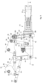
- Embodiments described using the attached drawings concern an apparatus to move products to be forged, indicated as a whole with reference number 10 in the attached drawings.
- the movement apparatus 10 comprises a manipulator 11 provided with a gripper 12 configured to support a product to be forged along a gripping axis X.
- the manipulator 11 has a mainly oblong development along the gripping axis X.
- the manipulator 11 is also provided with a mandrel 13 configured to rotate the gripper 12 around the gripping axis X and allow the correct orientation of the product to be forged.
- the mandrel 13 can comprise a hydraulic motor suitable to make the gripper 12 rotate around the gripping axis X.
- the mandrel 13 supports the gripper 12 cantilevered.
- the gripper 12 can be provided with at least two jaws 14 which can be opened and closed, and in which the product to be forged is held.
- the manipulator 11 is provided with three pivoting portions, that is, respectively a first front pivot 15, a second front pivot 16, and a third rear pivot 17 which substantially lie on the same support plane ⁇ .
- front pivot 15 and the rear pivot 17 can comprise through holes for the insertion of hinging members, as described below.
- the first front pivot 15 and the second front pivot 16 can be aligned along a common front pivoting axis Y1.
- the first front pivot 15 and the second front pivot 16 can be located in a symmetrical position with respect to the gripping axis X.
- the front pivoting axis Y1 lies on the support plane ⁇ as above, and can be substantially orthogonal to the gripping axis X.
- the axis of the third rear pivot 17 is aligned with an axis located on a median plane of the manipulator 11 itself. Furthermore, the axis of the third rear pivot 17 is distanced, along the gripping axis X, with respect to the first front pivot 15 and the second front pivot 16.
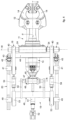
- the apparatus 10 comprises a front structure 18 connected to the first front pivot 15 and to the second front pivot 16, a rear structure 19 connected to the third rear pivot 17, and a movement slider 20 configured to support and move the front structure 18 and the rear structure 19.
- the front structure 18 comprises a first lever 21 and a second lever 22 connected respectively to the first front pivot 15 and to the second front pivot 16, and a damping device 23 connected to the first lever 21 and configured to damp, that is, cushion, the stresses suffered by the gripper 12 in a transverse direction with respect to the gripping axis X, by rotating the manipulator 11 on the support plane ⁇ and with respect to the third rear pivot 17.
- the damping device 23 can comprise a linear damper.
- the damping device 23 can comprise a hydraulic damper.
- the manipulator 11 maintains a stable positioning during determinate steps of the forging process, or that the manipulator 11, for example when a determinate stress in the transverse direction with respect to the gripping axis X is exceeded, can vary its position so as to prevent the stress from unloading onto the manipulator 11 causing damage and breakage. Once the stress has ceased, the damping device 23 allows the manipulator 11 to return to the correct position in the shortest time possible.
- the damping device 23 has a damping axis Z located transverse to the gripping axis X and, in this specific case, parallel, or substantially parallel, to the front pivoting axis Y1. This disposition allows to damp the stresses suffered by the gripper 15 in that direction.
- the front structure 18 comprises a front frame 24 provided with a first pivoting portion 25 and a second pivoting portion 26 to which respectively the first lever 21 and the second lever 22 are pivoted.
- the first pivoting portion 25 comprises a hinge 27 having a hinging axis Z1, orthogonal to the front pivoting axis Y1, for the hinging of the first lever 21.
- the second pivoting portion 26 comprises a spherical joint 28 configured to allow a spherical hinging of the second lever 22.
- the first pivoting portion 25 and the second pivoting portion 26 are aligned along a common axis, substantially parallel to the front pivoting axis Y1.
- the first lever 21 is provided with a first end 29 pivoted to the first front pivot 15 of the manipulator 11, with a second end 30, opposite the first end 29 and to which the damping device 23 is connected, and with a pivoting portion 31 interposed between the first end 29 and the second end 30 and pivoted to the front frame 24.
- the damping device 23 allows the first lever 21 to rotate in a controlled manner around the first pivoting portion 25, and therefore obtain the swiveling of the manipulator 11 on the support plane ⁇ , limiting the dynamic overloads of the structure.
- the damping device 23 is provided with a first end connected to the second end 30 of the first lever 21, and with a second end connected to the front frame 24.
- the second lever 22 is provided, in turn, with a first end 32 connected to the second front pivot 16, and with a second end 33, opposite the first end 32, and pivoted to the front frame 24.
- first front pivot 15 and the second front pivot 16 can comprise a spherical joint for the hinging respectively of the first lever 21 and of the second lever 22.
- the front structure 18 comprises a support shaft 34 configured to support the front frame 24 and allow a rotation thereof around an axis of rotation W.
- the support shaft 34 can have a cylindrical conformation, or be provided with at least one pivoting portion to which the front frame 24 is pivoted.
- the front frame 24 can be constrained at least axially, along the axis of rotation W, to the support shaft 34 by means of suitable abutment elements, not visible in the drawings.
- the front frame 24 is integrally attached to the support shaft 34, and the support shaft 34 is pivoted to the front frame 24, thus defining a pivoting axis for the latter.
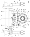
- a translation member 35 configured to translate the support shaft 34 and therefore also the front frame 24 associated therewith along the axis of rotation W.
- the translation member 35 can be integrated, at least partly, into the support shaft 34.
- the translation member 35 can comprise at least one plunger cylinder 36 provided at at least one end of the support shaft 34 and configured to translate the latter along the axis of rotation W.
- the plunger cylinder 36 can comprise a cavity 37 made open toward one end of the support shaft 34, and a guide piston 38 integrally attached to the front structure 18 and slidingly inserted into the cavity 37.
- the plunger cylinder 36 also comprises a jacket 39 of the cylinder in which the guide piston 38 is attached and in which an end portion of the support shaft 34 is slidingly inserted.
- the jacket 39, the guide piston 38 and the cavity 37 together define at least two drive chambers into at least one of which a drive fluid, usually hydraulic oil, is fed in order to axially move the support shaft 34 with respect to the front structure 18 itself.
- a drive fluid usually hydraulic oil
- the translation element 35 described above can also have the function of secondary damping, or limiting the transverse stresses, that is, acting in a direction parallel to the axis of rotation W, induced by the forging actions.
- the combined action of the damping device 23 and of the translation member 35 allows to damp the transverse stresses to which the gripper 15 is subjected, facilitating the precise repositioning operations of the latter, following a forging action, and reducing the damage and wear to which the components are subjected.
- the front structure 18 can comprise two front arms 40 pivoted, with their front pivoting portions 41, to the movement slider 20.
- the front arms 40 are pivoted to the support shaft 34 in correspondence with its ends.
- the drive plane ⁇ can be located, during use, substantially vertical.
- the front drive devices 42 can comprise two front actuators 43 each connected to the movement slider 20 and to one of the two front arms 40, and configured to rotate the front arms 40 themselves around the front pivoting portions 41.
- the front arms 40 can be connected to each other by a pivoting shaft 44.
- the front actuators 43 are connected to the ends of the pivoting shaft 44.
- the pivoting shaft 44 can be located substantially parallel to the axis of rotation W.
- the rear structure 19 can comprise a rear frame 45 pivoted, with a first end thereof, to the third rear pivot 17 and, with a second end thereof, opposite the first, to a connection body 46 of the rear structure 19.
- the third rear pivot 17 can comprise a spherical joint in order to allow a spherical movement of the manipulator 13.
- connection body 46 is connected to the movement slider 20.
- connection shaft 47 can have a rear pivoting axis R substantially parallel to the axis of rotation W.
- a translation device 48 can be associated with the rear frame 45 configured to translate the rear frame 45 along the connection shaft 47.
- the combined action of the translation member 35 and of the translation device 48 along the respective axes allows to obtain, within limited limits of movement, also a rotation of the manipulator 11 on the support plane ⁇ .
- the translation device 48 can comprise a jacket positioned sliding on the connection shaft 47 and defining a translating actuator with the latter.
- connection body 46 can be pivoted to the movement slider 20 in correspondence with rear pivoting portions 49.
- the rear pivoting portions 49 are aligned along a common pivoting axis Q.
- the rear structure 19 can comprise a damping member 51 connected to the rear frame 45, and configured to damp the stresses suffered by the gripper 12 in a direction parallel to the gripping axis X.
- the damping member 51 can lie on the drive plane ⁇ .
- the damping member 51 can be chosen in a group comprising a hydraulic damper, a spring, a rubberized element.
- the damping member 51 can be of the hydraulic type.
- the damping member 51 is connected to the rear frame 45 and the movement slider 20 by means of respective spherical joints 52.
- the damping member 51 can be connected to the rear frame 45 in an intermediate position between the third rear pivot 17 and the connection shaft 47. This embodiment configuration allows to be able to move the gripper 12 in a substantially vertical direction.
- connection body 46 is provided with first arms 50 attached integrally to the rear pivoting portions 49 and having respective ends pivoted with the rear frame 45, in this specific case pivoted to the connection shaft 47.
- connection body 46 can comprise second arms 53 attached integrally to the rear pivoting portions 49 and located at an angle with respect to the first arms 50.
- the first arms 50 and the second arms 53 are fixed each with respect to the others, that is, an angular rotation of the connection body 46 around the rear pivoting portions 49 determines an analogous angular rotation of the first arms 50 and of the second arms 53.
- connection body 46 and the front arms 40 are connected to each other by means of lateral actuators 54 configured to determine, in combination with the front actuators 43, a movement of the manipulator 11 on the drive plane ⁇ .
- the front arms 40 have an elbow-like conformation, and are provided with a first end to which the support shaft 34 of the front frame 24 is connected, and a second end to which the lateral actuators 54 are connected.
- the movement slider 20 is configured to be moved at least in a direction parallel to the gripping axis X.
- the movement slider 20 can comprise wheels 55 to allow the support and movement of the movement apparatus 10.
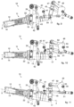
- the front actuators 43 are in the configuration of minimum extension, and the gripper 12 is supported by the mandrel 13 in a condition facing downward. By keeping the front actuators 43 in a fixed position, the front arms 40 are not rotated with respect to the front pivoting portions 41.
- the lateral actuators 54 are further extended and this causes an angular movement of the connection body 46 with a consequent rotation of the manipulator 11 on the drive plane ⁇ , in order to dispose the gripping axis X substantially horizontal.
- Fig. 8 shows another position of the manipulator 11 in which the connection body 46 has been further rotated with respect to the rear pivoting portions 49, in order to dispose the gripping axis X facing upward.
- the front actuators 43 are in the configuration of maximum extension.
- the lateral actuators 54 are taken in succession from a configuration of minor extension ( fig. 9 ) to a configuration of intermediate extension ( fig. 10 ) up to a configuration of maximum extension ( fig. 11 ).
- the second functioning mode is comparable to the first functioning mode.
Landscapes
- Engineering & Computer Science (AREA)
- Mechanical Engineering (AREA)
- Forging (AREA)
- Control And Other Processes For Unpacking Of Materials (AREA)
Claims (8)
- Vorrichtung, um zu schmiedende Produkte zu bewegen, welche aufweist:- einen Manipulator (11), der mit einem Greifer (12), der eingerichtet ist, um ein zu schmiedendes Produkt entlang einer Greifachse (X) zu halten, und einem ersten vorderen Gelenk (15), einem zweiten vorderen Gelenk (16), einem dritten hinteren Gelenk (17), die alle auf einer gemeinsamen Halteebene (π) liegen, versehen ist,- eine vordere Struktur (18), die mit dem ersten vorderen Gelenk (15) und mit dem zweiten vorderen Gelenk (16) verbunden ist,- eine hintere Struktur (19), die mit dem dritten hinteren Gelenk (17) verbunden ist,- einen Bewegungsschieber (20), der eingerichtet ist, um die vordere Struktur (18) und die hintere Struktur (19) zu halten,wobei die besagte vordere Struktur (18) einen ersten Hebel (21) und einen zweiten Hebel (22), die in zugeordneter Weise mit dem besagten ersten vorderen Gelenk (15) und mit dem besagten zweiten vorderen Gelenk (16) verbunden sind, und eine Dämpfungsvorrichtung (23), die einen Lineardämpfer oder einen hydraulischen Dämpfer aufweist, die mit dem besagten ersten Hebel (21) verbunden ist und die eingerichtet ist, um die Belastungen zu dämpfen, die von dem besagten Greifer (12) in einer Querrichtung in Bezug auf die besagte Greifachse (X) erlitten werden, durch Drehen des besagten Manipulators (11) auf der besagten Halteebene (n) und in Bezug auf das besagte dritte hintere Gelenk (17),wobei das besagte erste vordere Gelenk (15) und das besagte zweite vordere Gelenk (16) entlang einer gemeinsamen vorderen Gelenkachse (Y1) ausgerichtet sind, wobei die besagte Dämpfungsvorrichtung (23) eine Dämpfungsachse (Z) hat, die quer zur besagten Greifachse (X) angeordnet ist,wobei die besagte vordere Struktur (18) einen vorderen Rahmen (24) aufweist, der mit einem ersten Gelenkabschnitt (25) des besagten ersten Hebels (21) und einem zweiten Gelenkabschnitt (26) des besagten zweiten Hebels (22) versehen ist, wobei der besagte erste Gelenkabschnitt (25) ein Scharnier (27) aufweist, das eine Gelenkachse (Z1) hat, die orthogonal zu der besagten vorderen Gelenkachse (Y1) ist,dadurch gekennzeichnet, dass der besagte zweite Gelenkabschnitt (26) ein Kugelgelenk (28) aufweist, das eingerichtet ist, um ein sphärisches Schwenken des besagten zweiten Hebels (22) zu ermöglichen.
- Vorrichtung wie in Anspruch 1, dadurch gekennzeichnet, dass der besagte erste Hebel (21) mit einem ersten Ende (29), das mit dem besagten ersten vorderen Gelenk (15) gelenkverbunden ist, einem zweiten Ende (30), das entgegengesetzt zu dem ersten Ende (29) ist und mit welchem die besagte Dämpfungsvorrichtung (23) verbunden ist, und einem Gelenkabschnitt (31), welcher zwischen dem ersten Ende (29) und dem zweiten Ende (30) angeordnet ist und welcher mit dem besagten vorderen Rahmen (24) gelenkverbunden ist, versehen ist.
- Vorrichtung wie in irgendeinem vorherstehenden Anspruch, dadurch gekennzeichnet, dass die besagte hintere Struktur (19) einen hinteren Rahmen (45) aufweist, welcher, mit einem ersten Ende davon, mit dem besagten dritten hinteren Gelenk (17) und, mit einem zweiten Ende davon, welches entgegengesetzt zu dem ersten Ende ist, mit einem Verbindungskörper (46) der besagten hinteren Struktur (19) gelenkverbunden ist, und dadurch, dass die besagte hintere Struktur (19) ein Dämpfungselement (51) aufweist, welches mit dem hinteren Rahmen (45) verbunden ist und welches eingerichtet ist, um die Belastungen zu dämpfen, welche von dem besagten Greifer (12) in einer Richtung parallel zur besagten Greifachse (X) erlitten werden.
- Vorrichtung wie in Anspruch 3, dadurch gekennzeichnet, dass der hintere Rahmen (45) mittels eines Verbindungsschafts (47) mit dem besagten Verbindungskörper (46) gelenkverbunden ist, und dadurch, dass das besagte Dämpfungselement (51) mit dem besagten hinteren Rahmen (45) in einem Zwischenabschnitt zwischen dem besagten dritten hinteren Gelenk (17) und der besagten Verbindungswelle (47) verbunden ist.
- Vorrichtung wie in Anspruch 4, dadurch gekennzeichnet, dass eine Verschiebevorrichtung (48) mit dem besagten hinteren Rahmen (45) assoziiert ist, welche eingerichtet ist, um den besagten hinteren Rahmen (45) entlang des besagten Verbindungsschafts (47) zu verschieben.
- Vorrichtung wie in irgendeinem vorherstehenden Anspruch, dadurch gekennzeichnet, dass die besagte vordere Struktur (18) eine Haltewelle (34) aufweist, welche eingerichtet ist, um den besagten vorderen Rahmen (24) zu halten und eine Drehung des letzteren um eine Drehachse (W) herum zu ermöglichen.
- Vorrichtung wie in Anspruch 6, dadurch gekennzeichnet, dass ein Verschiebeelement (35) mit der besagten Haltewelle (34) assoziiert ist, welches eingerichtet ist, um die besagte Haltewelle (34) und den besagten vorderen Rahmen (24) entlang der besagten Drehachse (W) zu verschieben.
- Vorrichtung wie in irgendeinem vorherstehenden Anspruch, dadurch gekennzeichnet, dass vordere Vorrichtungen (42) mit der besagten vorderen Struktur (18) assoziiert sind, welche eingerichtet sind, um den besagten Manipulator (11) auf einer Antriebsebene (θ) zu bewegen, die quer zur Halteebene (n) angeordnet ist und auf welcher die besagte Greifachse (X) liegt.
Applications Claiming Priority (2)
| Application Number | Priority Date | Filing Date | Title |
|---|---|---|---|
| IT102018000020245A IT201800020245A1 (it) | 2018-12-20 | 2018-12-20 | Apparato di manipolazione di prodotti da forgiare |
| PCT/IT2019/050274 WO2020129105A1 (en) | 2018-12-20 | 2019-12-20 | Apparatus to manipulate products to be forged |
Publications (2)
| Publication Number | Publication Date |
|---|---|
| EP3898024A1 EP3898024A1 (de) | 2021-10-27 |
| EP3898024B1 true EP3898024B1 (de) | 2023-09-13 |
Family
ID=66049461
Family Applications (1)
| Application Number | Title | Priority Date | Filing Date |
|---|---|---|---|
| EP19839283.9A Active EP3898024B1 (de) | 2018-12-20 | 2019-12-20 | Vorrichtung zur handhabung von schmiedeprodukten |
Country Status (3)
| Country | Link |
|---|---|
| EP (1) | EP3898024B1 (de) |
| IT (1) | IT201800020245A1 (de) |
| WO (1) | WO2020129105A1 (de) |
Families Citing this family (2)
| Publication number | Priority date | Publication date | Assignee | Title |
|---|---|---|---|---|
| CN112676522B (zh) * | 2020-12-30 | 2025-01-10 | 大冶特殊钢有限公司 | 锻造操作机吊挂系统 |
| CN116117054B (zh) * | 2022-11-18 | 2024-01-30 | 江苏倍嘉力机械科技有限公司 | 一种汽车铝合金配件锻造装置 |
Family Cites Families (5)
| Publication number | Priority date | Publication date | Assignee | Title |
|---|---|---|---|---|
| FR1028869A (fr) * | 1949-10-17 | 1953-05-28 | Dango & Dienenthal Kommandit G | Dispositif muni d'un support de pince pour tenir et retourner de lourdes pièces de forge |
| US2864271A (en) * | 1953-02-11 | 1958-12-16 | Kendall Edgar Homer | Forging manipulator |
| IT939255B (it) | 1971-10-28 | 1973-02-10 | Padoin L | Dispositivo di bloccaggio a catenac cio di tipo incassato per serramen ti con maniglia di comando applica bile in qualsiasi posizione prefis sata |
| CN102019340B (zh) * | 2010-11-15 | 2012-09-05 | 沈阳重型机械集团有限责任公司 | 锻造操作机钳杆升降机构 |
| CN102935480B (zh) * | 2012-10-30 | 2014-12-10 | 燕山大学 | 运动少耦合型六自由度锻造操作机 |
-
2018
- 2018-12-20 IT IT102018000020245A patent/IT201800020245A1/it unknown
-
2019
- 2019-12-20 EP EP19839283.9A patent/EP3898024B1/de active Active
- 2019-12-20 WO PCT/IT2019/050274 patent/WO2020129105A1/en not_active Ceased
Also Published As
| Publication number | Publication date |
|---|---|
| IT201800020245A1 (it) | 2020-06-20 |
| WO2020129105A1 (en) | 2020-06-25 |
| EP3898024A1 (de) | 2021-10-27 |
Similar Documents
| Publication | Publication Date | Title |
|---|---|---|
| CN102059707B (zh) | 仿手指的自适应柔性夹具总成 | |
| EP3898024B1 (de) | Vorrichtung zur handhabung von schmiedeprodukten | |
| DE10128451A1 (de) | Schmiedemanipulator | |
| EP3329052B1 (de) | Greifmaschine | |
| US8061748B2 (en) | System for handling components having similar shapes by using two gripper jaws coupled to a common displacement drive | |
| US5299848A (en) | Tooling comprising tongs with two pivoted arms, with a release system | |
| JP6302461B2 (ja) | 平衡型空気圧マニピュレータ | |
| EP2452761B1 (de) | Clinch-Klemme | |
| US4873860A (en) | Lifting beam assembly for a forming press | |
| WO2015097107A1 (de) | Verfahren zum automatisierten drehfügen und/oder drehlösen von bauteilen, sowie zugehöriger industrieroboter und automatisierter montagearbeitsplatz | |
| DE102005033767A1 (de) | Vorrichtung zum Halten und Manipulieren von Werkstücken beim Massivumformen | |
| CN102489994A (zh) | 一种轮毂螺母装配设备 | |
| EP1628791B1 (de) | Handhabungsgerät zum handhaben eines werkstücks während eines umformprozesses | |
| US2864271A (en) | Forging manipulator | |
| EP1447155B1 (de) | Rollbördelwerkzeug und Bördelverfahren | |
| US20150273567A1 (en) | Upsetting press and method for upsetting of an end of longitudinally extending workpieces | |
| JP2014501180A (ja) | 改良型研削機械及び研削方法 | |
| US11654517B2 (en) | Fastener welding apparatus | |
| US3498490A (en) | Manipulators | |
| CN210387417U (zh) | 一种自动辊锻生产系统 | |
| EP2908966B1 (de) | C-rahmenstruktur für biegungsausgleich und zugehöriges verfahren | |
| JP2022515735A (ja) | 冶金鋳造設備 | |
| CN104785702B (zh) | 一种单驱动四指同步夹持的新型重载夹持装置 | |
| DE102005033540A1 (de) | Zum Greifen von Gegenständen ausgebildete Greifvorrichtung und Verfahren zum Greifen und Montieren von Gegenständen | |
| WO2011047660A1 (de) | Gedämpftes roboterhandgelenk für stossartige prozesskräfte |
Legal Events
| Date | Code | Title | Description |
|---|---|---|---|
| STAA | Information on the status of an ep patent application or granted ep patent |
Free format text: STATUS: UNKNOWN |
|
| STAA | Information on the status of an ep patent application or granted ep patent |
Free format text: STATUS: THE INTERNATIONAL PUBLICATION HAS BEEN MADE |
|
| PUAI | Public reference made under article 153(3) epc to a published international application that has entered the european phase |
Free format text: ORIGINAL CODE: 0009012 |
|
| STAA | Information on the status of an ep patent application or granted ep patent |
Free format text: STATUS: REQUEST FOR EXAMINATION WAS MADE |
|
| 17P | Request for examination filed |
Effective date: 20210622 |
|
| AK | Designated contracting states |
Kind code of ref document: A1 Designated state(s): AL AT BE BG CH CY CZ DE DK EE ES FI FR GB GR HR HU IE IS IT LI LT LU LV MC MK MT NL NO PL PT RO RS SE SI SK SM TR |
|
| DAV | Request for validation of the european patent (deleted) | ||
| DAX | Request for extension of the european patent (deleted) | ||
| STAA | Information on the status of an ep patent application or granted ep patent |
Free format text: STATUS: EXAMINATION IS IN PROGRESS |
|
| 17Q | First examination report despatched |
Effective date: 20220725 |
|
| GRAP | Despatch of communication of intention to grant a patent |
Free format text: ORIGINAL CODE: EPIDOSNIGR1 |
|
| STAA | Information on the status of an ep patent application or granted ep patent |
Free format text: STATUS: GRANT OF PATENT IS INTENDED |
|
| INTG | Intention to grant announced |
Effective date: 20230330 |
|
| P01 | Opt-out of the competence of the unified patent court (upc) registered |
Effective date: 20230527 |
|
| GRAS | Grant fee paid |
Free format text: ORIGINAL CODE: EPIDOSNIGR3 |
|
| GRAA | (expected) grant |
Free format text: ORIGINAL CODE: 0009210 |
|
| STAA | Information on the status of an ep patent application or granted ep patent |
Free format text: STATUS: THE PATENT HAS BEEN GRANTED |
|
| AK | Designated contracting states |
Kind code of ref document: B1 Designated state(s): AL AT BE BG CH CY CZ DE DK EE ES FI FR GB GR HR HU IE IS IT LI LT LU LV MC MK MT NL NO PL PT RO RS SE SI SK SM TR |
|
| REG | Reference to a national code |
Ref country code: CH Ref legal event code: EP |
|
| REG | Reference to a national code |
Ref country code: DE Ref legal event code: R096 Ref document number: 602019037558 Country of ref document: DE |
|
| REG | Reference to a national code |
Ref country code: IE Ref legal event code: FG4D |
|
| REG | Reference to a national code |
Ref country code: LT Ref legal event code: MG9D |
|
| REG | Reference to a national code |
Ref country code: NL Ref legal event code: MP Effective date: 20230913 |
|
| PG25 | Lapsed in a contracting state [announced via postgrant information from national office to epo] |
Ref country code: GR Free format text: LAPSE BECAUSE OF FAILURE TO SUBMIT A TRANSLATION OF THE DESCRIPTION OR TO PAY THE FEE WITHIN THE PRESCRIBED TIME-LIMIT Effective date: 20231214 |
|
| PG25 | Lapsed in a contracting state [announced via postgrant information from national office to epo] |
Ref country code: SE Free format text: LAPSE BECAUSE OF FAILURE TO SUBMIT A TRANSLATION OF THE DESCRIPTION OR TO PAY THE FEE WITHIN THE PRESCRIBED TIME-LIMIT Effective date: 20230913 Ref country code: RS Free format text: LAPSE BECAUSE OF FAILURE TO SUBMIT A TRANSLATION OF THE DESCRIPTION OR TO PAY THE FEE WITHIN THE PRESCRIBED TIME-LIMIT Effective date: 20230913 Ref country code: NO Free format text: LAPSE BECAUSE OF FAILURE TO SUBMIT A TRANSLATION OF THE DESCRIPTION OR TO PAY THE FEE WITHIN THE PRESCRIBED TIME-LIMIT Effective date: 20231213 Ref country code: LV Free format text: LAPSE BECAUSE OF FAILURE TO SUBMIT A TRANSLATION OF THE DESCRIPTION OR TO PAY THE FEE WITHIN THE PRESCRIBED TIME-LIMIT Effective date: 20230913 Ref country code: LT Free format text: LAPSE BECAUSE OF FAILURE TO SUBMIT A TRANSLATION OF THE DESCRIPTION OR TO PAY THE FEE WITHIN THE PRESCRIBED TIME-LIMIT Effective date: 20230913 Ref country code: HR Free format text: LAPSE BECAUSE OF FAILURE TO SUBMIT A TRANSLATION OF THE DESCRIPTION OR TO PAY THE FEE WITHIN THE PRESCRIBED TIME-LIMIT Effective date: 20230913 Ref country code: GR Free format text: LAPSE BECAUSE OF FAILURE TO SUBMIT A TRANSLATION OF THE DESCRIPTION OR TO PAY THE FEE WITHIN THE PRESCRIBED TIME-LIMIT Effective date: 20231214 Ref country code: FI Free format text: LAPSE BECAUSE OF FAILURE TO SUBMIT A TRANSLATION OF THE DESCRIPTION OR TO PAY THE FEE WITHIN THE PRESCRIBED TIME-LIMIT Effective date: 20230913 |
|
| REG | Reference to a national code |
Ref country code: AT Ref legal event code: MK05 Ref document number: 1610753 Country of ref document: AT Kind code of ref document: T Effective date: 20230913 |
|
| PG25 | Lapsed in a contracting state [announced via postgrant information from national office to epo] |
Ref country code: NL Free format text: LAPSE BECAUSE OF FAILURE TO SUBMIT A TRANSLATION OF THE DESCRIPTION OR TO PAY THE FEE WITHIN THE PRESCRIBED TIME-LIMIT Effective date: 20230913 |
|
| PG25 | Lapsed in a contracting state [announced via postgrant information from national office to epo] |
Ref country code: IS Free format text: LAPSE BECAUSE OF FAILURE TO SUBMIT A TRANSLATION OF THE DESCRIPTION OR TO PAY THE FEE WITHIN THE PRESCRIBED TIME-LIMIT Effective date: 20240113 |
|
| PG25 | Lapsed in a contracting state [announced via postgrant information from national office to epo] |
Ref country code: AT Free format text: LAPSE BECAUSE OF FAILURE TO SUBMIT A TRANSLATION OF THE DESCRIPTION OR TO PAY THE FEE WITHIN THE PRESCRIBED TIME-LIMIT Effective date: 20230913 |
|
| PG25 | Lapsed in a contracting state [announced via postgrant information from national office to epo] |
Ref country code: ES Free format text: LAPSE BECAUSE OF FAILURE TO SUBMIT A TRANSLATION OF THE DESCRIPTION OR TO PAY THE FEE WITHIN THE PRESCRIBED TIME-LIMIT Effective date: 20230913 |
|
| PG25 | Lapsed in a contracting state [announced via postgrant information from national office to epo] |
Ref country code: SM Free format text: LAPSE BECAUSE OF FAILURE TO SUBMIT A TRANSLATION OF THE DESCRIPTION OR TO PAY THE FEE WITHIN THE PRESCRIBED TIME-LIMIT Effective date: 20230913 Ref country code: RO Free format text: LAPSE BECAUSE OF FAILURE TO SUBMIT A TRANSLATION OF THE DESCRIPTION OR TO PAY THE FEE WITHIN THE PRESCRIBED TIME-LIMIT Effective date: 20230913 Ref country code: IS Free format text: LAPSE BECAUSE OF FAILURE TO SUBMIT A TRANSLATION OF THE DESCRIPTION OR TO PAY THE FEE WITHIN THE PRESCRIBED TIME-LIMIT Effective date: 20240113 Ref country code: ES Free format text: LAPSE BECAUSE OF FAILURE TO SUBMIT A TRANSLATION OF THE DESCRIPTION OR TO PAY THE FEE WITHIN THE PRESCRIBED TIME-LIMIT Effective date: 20230913 Ref country code: EE Free format text: LAPSE BECAUSE OF FAILURE TO SUBMIT A TRANSLATION OF THE DESCRIPTION OR TO PAY THE FEE WITHIN THE PRESCRIBED TIME-LIMIT Effective date: 20230913 Ref country code: CZ Free format text: LAPSE BECAUSE OF FAILURE TO SUBMIT A TRANSLATION OF THE DESCRIPTION OR TO PAY THE FEE WITHIN THE PRESCRIBED TIME-LIMIT Effective date: 20230913 Ref country code: AT Free format text: LAPSE BECAUSE OF FAILURE TO SUBMIT A TRANSLATION OF THE DESCRIPTION OR TO PAY THE FEE WITHIN THE PRESCRIBED TIME-LIMIT Effective date: 20230913 Ref country code: PT Free format text: LAPSE BECAUSE OF FAILURE TO SUBMIT A TRANSLATION OF THE DESCRIPTION OR TO PAY THE FEE WITHIN THE PRESCRIBED TIME-LIMIT Effective date: 20240115 Ref country code: SK Free format text: LAPSE BECAUSE OF FAILURE TO SUBMIT A TRANSLATION OF THE DESCRIPTION OR TO PAY THE FEE WITHIN THE PRESCRIBED TIME-LIMIT Effective date: 20230913 |
|
| PG25 | Lapsed in a contracting state [announced via postgrant information from national office to epo] |
Ref country code: PL Free format text: LAPSE BECAUSE OF FAILURE TO SUBMIT A TRANSLATION OF THE DESCRIPTION OR TO PAY THE FEE WITHIN THE PRESCRIBED TIME-LIMIT Effective date: 20230913 |
|
| REG | Reference to a national code |
Ref country code: DE Ref legal event code: R097 Ref document number: 602019037558 Country of ref document: DE |
|
| PG25 | Lapsed in a contracting state [announced via postgrant information from national office to epo] |
Ref country code: DK Free format text: LAPSE BECAUSE OF FAILURE TO SUBMIT A TRANSLATION OF THE DESCRIPTION OR TO PAY THE FEE WITHIN THE PRESCRIBED TIME-LIMIT Effective date: 20230913 |
|
| PLBE | No opposition filed within time limit |
Free format text: ORIGINAL CODE: 0009261 |
|
| STAA | Information on the status of an ep patent application or granted ep patent |
Free format text: STATUS: NO OPPOSITION FILED WITHIN TIME LIMIT |
|
| PG25 | Lapsed in a contracting state [announced via postgrant information from national office to epo] |
Ref country code: DK Free format text: LAPSE BECAUSE OF FAILURE TO SUBMIT A TRANSLATION OF THE DESCRIPTION OR TO PAY THE FEE WITHIN THE PRESCRIBED TIME-LIMIT Effective date: 20230913 |
|
| REG | Reference to a national code |
Ref country code: CH Ref legal event code: PL |
|
| 26N | No opposition filed |
Effective date: 20240614 |
|
| PG25 | Lapsed in a contracting state [announced via postgrant information from national office to epo] |
Ref country code: LU Free format text: LAPSE BECAUSE OF NON-PAYMENT OF DUE FEES Effective date: 20231220 |
|
| PG25 | Lapsed in a contracting state [announced via postgrant information from national office to epo] |
Ref country code: MC Free format text: LAPSE BECAUSE OF FAILURE TO SUBMIT A TRANSLATION OF THE DESCRIPTION OR TO PAY THE FEE WITHIN THE PRESCRIBED TIME-LIMIT Effective date: 20230913 |
|
| GBPC | Gb: european patent ceased through non-payment of renewal fee |
Effective date: 20231220 |
|
| REG | Reference to a national code |
Ref country code: BE Ref legal event code: MM Effective date: 20231231 |
|
| PG25 | Lapsed in a contracting state [announced via postgrant information from national office to epo] |
Ref country code: MC Free format text: LAPSE BECAUSE OF FAILURE TO SUBMIT A TRANSLATION OF THE DESCRIPTION OR TO PAY THE FEE WITHIN THE PRESCRIBED TIME-LIMIT Effective date: 20230913 Ref country code: LU Free format text: LAPSE BECAUSE OF NON-PAYMENT OF DUE FEES Effective date: 20231220 |
|
| REG | Reference to a national code |
Ref country code: IE Ref legal event code: MM4A |
|
| PG25 | Lapsed in a contracting state [announced via postgrant information from national office to epo] |
Ref country code: IE Free format text: LAPSE BECAUSE OF NON-PAYMENT OF DUE FEES Effective date: 20231220 |
|
| PG25 | Lapsed in a contracting state [announced via postgrant information from national office to epo] |
Ref country code: GB Free format text: LAPSE BECAUSE OF NON-PAYMENT OF DUE FEES Effective date: 20231220 |
|
| PG25 | Lapsed in a contracting state [announced via postgrant information from national office to epo] |
Ref country code: BE Free format text: LAPSE BECAUSE OF NON-PAYMENT OF DUE FEES Effective date: 20231231 |
|
| PG25 | Lapsed in a contracting state [announced via postgrant information from national office to epo] |
Ref country code: FR Free format text: LAPSE BECAUSE OF NON-PAYMENT OF DUE FEES Effective date: 20231231 |
|
| PG25 | Lapsed in a contracting state [announced via postgrant information from national office to epo] |
Ref country code: CH Free format text: LAPSE BECAUSE OF NON-PAYMENT OF DUE FEES Effective date: 20231231 |
|
| PG25 | Lapsed in a contracting state [announced via postgrant information from national office to epo] |
Ref country code: SI Free format text: LAPSE BECAUSE OF FAILURE TO SUBMIT A TRANSLATION OF THE DESCRIPTION OR TO PAY THE FEE WITHIN THE PRESCRIBED TIME-LIMIT Effective date: 20230913 |
|
| PG25 | Lapsed in a contracting state [announced via postgrant information from national office to epo] |
Ref country code: SI Free format text: LAPSE BECAUSE OF FAILURE TO SUBMIT A TRANSLATION OF THE DESCRIPTION OR TO PAY THE FEE WITHIN THE PRESCRIBED TIME-LIMIT Effective date: 20230913 Ref country code: IE Free format text: LAPSE BECAUSE OF NON-PAYMENT OF DUE FEES Effective date: 20231220 Ref country code: GB Free format text: LAPSE BECAUSE OF NON-PAYMENT OF DUE FEES Effective date: 20231220 Ref country code: FR Free format text: LAPSE BECAUSE OF NON-PAYMENT OF DUE FEES Effective date: 20231231 Ref country code: CH Free format text: LAPSE BECAUSE OF NON-PAYMENT OF DUE FEES Effective date: 20231231 Ref country code: BE Free format text: LAPSE BECAUSE OF NON-PAYMENT OF DUE FEES Effective date: 20231231 |
|
| PG25 | Lapsed in a contracting state [announced via postgrant information from national office to epo] |
Ref country code: BG Free format text: LAPSE BECAUSE OF FAILURE TO SUBMIT A TRANSLATION OF THE DESCRIPTION OR TO PAY THE FEE WITHIN THE PRESCRIBED TIME-LIMIT Effective date: 20230913 |
|
| PG25 | Lapsed in a contracting state [announced via postgrant information from national office to epo] |
Ref country code: BG Free format text: LAPSE BECAUSE OF FAILURE TO SUBMIT A TRANSLATION OF THE DESCRIPTION OR TO PAY THE FEE WITHIN THE PRESCRIBED TIME-LIMIT Effective date: 20230913 |
|
| PG25 | Lapsed in a contracting state [announced via postgrant information from national office to epo] |
Ref country code: CY Free format text: LAPSE BECAUSE OF FAILURE TO SUBMIT A TRANSLATION OF THE DESCRIPTION OR TO PAY THE FEE WITHIN THE PRESCRIBED TIME-LIMIT; INVALID AB INITIO Effective date: 20191220 |
|
| PG25 | Lapsed in a contracting state [announced via postgrant information from national office to epo] |
Ref country code: HU Free format text: LAPSE BECAUSE OF FAILURE TO SUBMIT A TRANSLATION OF THE DESCRIPTION OR TO PAY THE FEE WITHIN THE PRESCRIBED TIME-LIMIT; INVALID AB INITIO Effective date: 20191220 |
|
| PG25 | Lapsed in a contracting state [announced via postgrant information from national office to epo] |
Ref country code: TR Free format text: LAPSE BECAUSE OF FAILURE TO SUBMIT A TRANSLATION OF THE DESCRIPTION OR TO PAY THE FEE WITHIN THE PRESCRIBED TIME-LIMIT Effective date: 20230913 |
|
| PGFP | Annual fee paid to national office [announced via postgrant information from national office to epo] |
Ref country code: IT Payment date: 20251015 Year of fee payment: 7 |
|
| PGFP | Annual fee paid to national office [announced via postgrant information from national office to epo] |
Ref country code: DE Payment date: 20251229 Year of fee payment: 7 |