EP3898112B1 - Setzgerät - Google Patents
Setzgerät Download PDFInfo
- Publication number
- EP3898112B1 EP3898112B1 EP19808839.5A EP19808839A EP3898112B1 EP 3898112 B1 EP3898112 B1 EP 3898112B1 EP 19808839 A EP19808839 A EP 19808839A EP 3898112 B1 EP3898112 B1 EP 3898112B1
- Authority
- EP
- European Patent Office
- Prior art keywords
- driving
- rotor
- setting
- rotation
- drive
- Prior art date
- Legal status (The legal status is an assumption and is not a legal conclusion. Google has not performed a legal analysis and makes no representation as to the accuracy of the status listed.)
- Active
Links
Images

Classifications
-
- B—PERFORMING OPERATIONS; TRANSPORTING
- B25—HAND TOOLS; PORTABLE POWER-DRIVEN TOOLS; MANIPULATORS
- B25C—HAND-HELD NAILING OR STAPLING TOOLS; MANUALLY OPERATED PORTABLE STAPLING TOOLS
- B25C1/00—Hand-held nailing tools; Nail feeding devices
- B25C1/04—Hand-held nailing tools; Nail feeding devices operated by fluid pressure, e.g. by air pressure
- B25C1/047—Mechanical details
-
- B—PERFORMING OPERATIONS; TRANSPORTING
- B25—HAND TOOLS; PORTABLE POWER-DRIVEN TOOLS; MANIPULATORS
- B25C—HAND-HELD NAILING OR STAPLING TOOLS; MANUALLY OPERATED PORTABLE STAPLING TOOLS
- B25C1/00—Hand-held nailing tools; Nail feeding devices
- B25C1/04—Hand-held nailing tools; Nail feeding devices operated by fluid pressure, e.g. by air pressure
-
- B—PERFORMING OPERATIONS; TRANSPORTING
- B25—HAND TOOLS; PORTABLE POWER-DRIVEN TOOLS; MANIPULATORS
- B25C—HAND-HELD NAILING OR STAPLING TOOLS; MANUALLY OPERATED PORTABLE STAPLING TOOLS
- B25C1/00—Hand-held nailing tools; Nail feeding devices
- B25C1/06—Hand-held nailing tools; Nail feeding devices operated by electric power
Definitions
- the invention relates to a setting device for driving fastening elements into a substrate in a setting direction.
- Such devices usually comprise a driving element which can be moved back and forth between a starting position and a setting position, a drive which drives the driving element in the setting direction from the starting position to the setting position in order to transmit energy to a fastening element, and a resetting device which Driving element transported back against the setting direction from the setting position to the starting position.
- the object of the invention is to provide a device for driving a fastening element into a substrate, in which such a return of the driving element is improved.
- the object is achieved with a setting tool for driving fasteners into a substrate in a setting direction, with a driving element which can be moved back and forth between a starting position and a setting position, with a drive, which is intended to drive the driving element in the setting direction from the starting position to the setting position in order to transfer energy to a fastening element, with a restoring device which is intended to convey the driving element against the setting direction from the setting position to the starting position, the restoring device a rotor that can be rotated about an axis of rotation and a driver element attached to the rotor, which can be brought into engagement with the driving element in order to drive the driving element along against the setting direction, the driver element being attached to the rotor so that it can move radially with respect to the axis of rotation, so that when the rotor rotates, the driver element moves away from the axis of rotation in order to engage the drive-in element.
- the restoring device comprises a spring which acts between the rotor and the driver element and loads the driver element towards the axis of rotation.
- the driver element and the drive-in element disengage again by themselves as soon as the rotation of the rotor has ended.
- An advantageous embodiment is characterized in that the drive-in element has one or more indentations in which the driver element engages when the driver element is in engagement with the drive-in element.
- the restoring device comprises a plurality of driver elements attached to the rotor.
- the driver elements are preferably at equal distances from one another in relation to the axis of rotation in the circumferential direction.
- the drive is provided to set the rotor in rotation.
- the drive preferably includes a flywheel which is intended to drive the driving element in the driving direction and to set the rotor in rotation in order to convey the driving element against the driving direction.
- the drive comprises a motor which is intended to set the rotor in rotation in order to convey the driving-in element counter to the driving-in direction.
- a likewise advantageous embodiment is characterized in that the restoring device comprises a motor which is separate from the drive and which is responsible for this it is provided to set the rotor in rotation in order to convey the driving-in element against the driving-in direction.
- the setting tool 10 comprises a driving-in element 40, preferably designed as a setting piston, which can be moved back and forth between an initial position and a setting position. Furthermore, the setting tool 10 comprises a drive 50, which is provided for driving the driving element 40 in the setting direction 30 from the in 1 To drive the starting position shown to the setting position to transmit energy to a fastener 20.
- the drive 50 comprises an energy store, for example a potential energy store such as a mechanical or pneumatic spring or an electrical energy store such as a capacitor and an energy transmission device which is intended to transfer energy from an electrical energy source 55, for example an electric battery, to the energy store .
- the drive 50 is provided for suddenly discharging the energy store in order to transfer the energy stored therein to the driving element 40 .
- the setting tool 10 includes a resetting device 60, which is intended to convey the driving element 10 against the setting direction 30 from the setting position to the starting position.
- the restoring device 60 comprises a rotor 80 rotatable about an axis of rotation 70 and four driver elements 90 attached to the rotor 80, which with respect to FIG the axis of rotation 70 have the same distances from one another in the circumferential direction.
- the driving element 40 has a plurality of indentations 41 which are arranged opposite the driver elements 90 in such a way that the driver elements 90 can be brought into engagement with the depressions 41 in order to take the driving element 40 along against the setting direction 30 .
- the driver elements 90 are attached to the rotor 80 so that they can move radially in relation to the axis of rotation 70, so that when the rotor 80 rotates, the driver elements 90 move away from the axis of rotation 70 radially outwards in order to engage with the depressions 41 of the drive-in element 40 come. This happens, for example, due to the centrifugal force that occurs during rotation.
- the driver elements each have an air deflection surface that is inclined relative to a circumferential direction of the rotor and deflects the air toward the axis of rotation in order to accelerate the respective driver element away from the axis of rotation.
- the restoring device 60 comprises four springs 91 which act between the rotor 80 and a respective driver element 90 in order to load the respective driver element 90 onto the axis of rotation 70 .
- the restoring device 60 comprises a motor that is separate from the drive 50 . In 1 the motor is covered by the rotor 80 and is intended to rotate the rotor 80 in a clockwise direction in order to convey the driving-in element 40 against the driving-in direction 30 .
- the resetting device 60 is shown in a view in the driving direction.
- the resetting device 60 comprises the axis of rotation 70, the rotor 80 designed as a disk, the driver elements 90 and the motor 95.
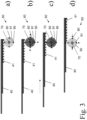
- the driving element 40 is shown with the resetting device 60 in several phases of a resetting process.
- the driving element is in the setting position, the rotor 80 does not rotate ( Figure 3a ).
- the rotor 80 is set in rotation about the axis of rotation 70, so that the driver elements 90 successively engage in the depressions 41 of the driving element 40 ( Figure 3b ).
- the driving-in element 40 is driven counter to the driving-in direction (in 3 to the right) moved ( 3c ).
- the rotation of the rotor 80 is stopped, so that the driver elements 90 disengage from the depressions 41 ( 3d ).
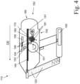
- the setting tool 110 includes a driving member 140 which is reciprocally movable between a home position and a set position. Furthermore, the setting tool 110 includes a drive 150 which is provided for driving the driving element 140 in the setting direction 130 from the starting position to the setting position in order to transfer energy to a fastening element 120 .
- the drive 150 comprises a flywheel 151 and an energy transfer device 152 which is intended to transfer energy from an electrical energy source 155, for example an electric battery, to the flywheel 151.
- the drive 50 is intended to press the drive-in element 140 against the flywheel 151 by means of a counter-roller 153 in order to transfer the energy stored in the flywheel 151 to the drive-in element 140 .
- This is done with a wedge 154, which is moved towards the counter-roller by means of an electromagnetic actuating element 155, for example.
- the setting tool 110 includes a resetting device 160, which is intended to convey the driving-in element 110 against the setting direction 130 from the setting position to the starting position.
- the restoring device 160 comprises a rotor 180 which can be rotated about an axis of rotation 170 and four driver elements 190 which are attached to the rotor 180 and which have the same spacing from one another in the circumferential direction in relation to the axis of rotation 170 .
- the driving element 140 has a plurality of indentations 141 which are arranged opposite the driver elements 190 in such a way that the driver elements 190 can be brought into engagement with the depressions 141 in order to take the driving element 140 along against the setting direction 130 .
- driver elements 190 are attached to rotor 180 so that they can move radially in relation to axis of rotation 170, so that when rotor 180 rotates, driver elements 190 move radially outwards away from axis of rotation 170 in order to engage with depressions 141 of drive-in element 140 come.
- the restoring device 160 comprises four springs 191 which act between the rotor 180 and a respective driver element 190 in order to load the respective driver element 190 towards the axis of rotation 170 .
- the driver elements 190 and the drive-in element 140 are disengaged when the rotor is not rotating.
- the drive 150 in the present example the energy transmission device 152, comprises a motor 156 which on the one hand transmits energy to the flywheel 151 and on the other hand rotates the rotor 180 in order to convey the driving element 140 against the driving direction.
Landscapes
- Engineering & Computer Science (AREA)
- Mechanical Engineering (AREA)
- Physics & Mathematics (AREA)
- Fluid Mechanics (AREA)
- Portable Nailing Machines And Staplers (AREA)
Description
- Die Erfindung betrifft ein Setzgerät zum Eintreiben von Befestigungselementen in einer Setzrichtung in einen Untergrund.
- Derartige Vorrichtungen umfassen üblicherweise ein Eintreibelement, welches zwischen einer Ausgangsposition und einer Setzposition hin und her bewegbar ist, einen Antrieb, welcher das Eintreibelement in der Setzrichtung von der Ausgangsposition zur Setzposition antreibt, um Energie auf ein Befestigungselement zu übertragen, und eine Rückstelleinrichtung, welche das Eintreibelement gegen die Setzrichtung von der Setzposition zur Ausgangsposition zurückbefördert.
- Aus der
US 2018/0154505 A1 ist ein Setzgerät mit einem als Zahnstange ausgebildeten Eintreibelement gemäß dem Oberbegriff des Anspruchs 1 bekannt, bei dem eine Rückstelleinrichtung für das Eintreibelement einen Rotor aufweist. Für eine Rückstellung des Eintreibelements greift der rotierende Rotor in die Zahnstange ein. - Aufgabe der Erfindung ist es, eine Vorrichtung zum Eintreiben eines Befestigungselements in einen Untergrund zur Verfügung zu stellen, bei der eine solche Rückstellung des Eintreibelements verbessert ist.
- Die Aufgabe ist gelöst bei einem Setzgerät zum Eintreiben von Befestigungselementen in einer Setzrichtung in einen Untergrund, mit einem Eintreibelement, welches zwischen einer Ausgangsposition und einer Setzposition hin und her bewegbar ist, mit einem Antrieb, welcher dafür vorgesehen ist, das Eintreibelement in der Setzrichtung von der Ausgangsposition zur Setzposition anzutreiben, um Energie auf ein Befestigungselement zu übertragen, mit einer Rückstelleinrichtung, welche dafür vorgesehen ist, das Eintreibelement gegen die Setzrichtung von der Setzposition zur Ausgangsposition zu befördern, wobei die Rückstelleinrichtung einen um eine Drehachse rotierbaren Rotor und ein an dem Rotor angebrachtes Mitnahmeelement umfasst, welches mit dem Eintreibelement in Eingriff bringbar ist, um das Eintreibelement gegen die Setzrichtung mitzunehmen, wobei das Mitnahmeelement in Bezug auf die Drehachse radial bewegbar an dem Rotor angebracht ist, so dass sich das Mitnahmeelement bei Rotation des Rotors von der Drehachse wegbewegt, um mit dem Eintreibelement in Eingriff zu kommen. Dadurch kommt das Mitnahmeelement von selbst in Eingriff mit dem Eintreibelement, so dass die Rückstellung des Eintreibelements vereinfacht ist. Die Rückstelleinrichtung umfasst eine Feder, welche zwischen dem Rotor und dem Mitnahmeelement wirkt und das Mitnahmeelement auf die Drehachse zu belastet. Dadurch kommen das Mitnahmeelement und das Eintreibelement auch von selbst wieder ausser Eingriff, sobald die Rotation des Rotors beendet wird.
- Eine vorteilhafte Ausführungsform ist dadurch gekennzeichnet, dass das Eintreibelement eine oder mehrere Vertiefungen aufweist, in welche das Mitnahmeelement eingreift, wenn das Mitnahmeelement mit dem Eintreibelement in Eingriff ist.
- Eine vorteilhafte Ausführungsform ist dadurch gekennzeichnet, dass die Rückstelleinrichtung mehrere an dem Rotor angebrachte Mitnahmeelemente umfasst. Bevorzugt weisen die Mitnahmeelemente in Bezug auf die Drehachse in Umfangsrichtung gleiche Abstände zueinander auf.
- Eine vorteilhafte Ausführungsform ist dadurch gekennzeichnet, dass der Antrieb dafür vorgesehen ist, den Rotor in Rotation zu versetzen. Bevorzugt umfasst der Antrieb ein Schwungrad, welches dafür vorgesehen ist, das Eintreibelement in der Eintreibrichtung anzutreiben und den Rotor in Rotation zu versetzen, um das Eintreibelement gegen die Eintreibrichtung zu befördern. Ebenfalls bevorzugt umfasst der Antrieb einen Motor, welcher dafür vorgesehen ist, den Rotor in Rotation zu versetzen, um das Eintreibelement gegen die Eintreibrichtung zu befördern.
- Eine ebenfalls vorteilhafte Ausführungsform ist dadurch gekennzeichnet, dass die Rückstelleinrichtung einen von dem Antrieb separaten Motor umfasst, welcher dafür vorgesehen ist, den Rotor in Rotation zu versetzen, um das Eintreibelement gegen die Eintreibrichtung zu befördern.
- Weitere Vorteile, Merkmale und Einzelheiten der Erfindung ergeben sich aus der nachfolgenden Beschreibung, in der unter Bezugnahme auf die Zeichnung verschiedene Ausführungsbeispiele im Einzelnen beschrieben sind. Es zeigen:
- Fig. 1
- schematisch ein Setzgerät,
- Fig. 2
- eine Rückstelleinrichtung,
- Fig. 3
- ein Eintreibelement und eine Rückstelleinrichtung während eines Rückstellvorgangs,
- Fig. 4
- schematisch ein Setzgerät.
- In
Fig. 1 ist ein Setzgerät 10 zum Eintreiben von Befestigungselementen 20 in einer Setzrichtung 30 in einen Untergrund schematisch dargestellt. Das Setzgerät 10 umfasst ein bevorzugt als Setzkolben ausgebildetes Eintreibelement 40, welches zwischen einer Ausgangsposition und einer Setzposition hin und her bewegbar ist. Weiterhin umfasst das Setzgerät 10 einen Antrieb 50, welcher dafür vorgesehen ist, das Eintreibelement 40 in der Setzrichtung 30 von der inFig. 1 dargestellten Ausgangsposition zur Setzposition anzutreiben, um Energie auf ein Befestigungselement 20 zu übertragen. Der Antrieb 50 umfasst einen Energiespeicher, beispielsweise einen potentiellen Energiespeicher wie eine mechanische oder pneumatische Feder oder einen elektrischen Energiespeicher wie einen Kondensator und eine Energieübertragungsvorrichtung, welche dafür vorgesehen ist, Energie aus einer elektrischen Energiequelle 55, beispielsweise einer elektrischen Batterie, auf den Energiespeicher zu übertragen. Der Antrieb 50 ist dafür vorgesehen, den Energiespeicher schlagartig zu entladen, um die darin gespeicherte Energie auf das Eintreibelement 40 zu übertragen. - Das Setzgerät 10 umfasst eine Rückstelleinrichtung 60, welche dafür vorgesehen ist, das Eintreibelement 10 gegen die Setzrichtung 30 von der Setzposition zur Ausgangsposition zu befördern. Die Rückstelleinrichtung 60 umfasst einen um eine Drehachse 70 rotierbaren Rotor 80 und vier an dem Rotor 80 angebrachte Mitnahmeelemente 90, welche in Bezug auf die Drehachse 70 in Umfangsrichtung gleiche Abstände zueinander aufweisen. Das Eintreibelement 40 weist mehrere Vertiefungen 41 auf, welche so den Mitnahmeelementen 90 gegenüber angeordnet sind, dass die Mitnahmeelemente 90 mit den Vertiefungen 41 in Eingriff bringbar sind, um das Eintreibelement 40 gegen die Setzrichtung 30 mitzunehmen. Die Mitnahmeelemente 90 sind hierzu in Bezug auf die Drehachse 70 radial bewegbar an dem Rotor 80 angebracht, so dass sich die Mitnahmeelemente 90 bei Rotation des Rotors 80 von der Drehachse 70 radial nach aussen wegbewegen, um mit den Vertiefungen 41 des Eintreibelements 40 in Eingriff zu kommen. Dies geschieht beispielsweise aufgrund der bei der Rotation auftretenden Fliehkraft. Bei nicht gezeigten Ausführungsbeispielen weisen die Mitnahmeelemente jeweils eine gegenüber einer Umfangsrichtung des Rotors geneigte Luftabweisfläche auf, welche die Luft auf die Drehachse zu abweist, um das jeweilige Mitnahmeelement von der Drehachse weg zu beschleunigen. Die Rückstelleinrichtung 60 umfasst vier Federn 91, welche zwischen dem Rotor 80 und jeweils einem Mitnahmeelement 90 wirken, um das jeweilige Mitnahmeelement 90 auf die Drehachse 70 zu zu belasten. Dadurch sind die Mitnahmeelemente 90 und das Eintreibelement 40 ausser Eingriff, wenn der Rotor nicht rotiert. Die Rückstelleinrichtung 60 umfasst einen von dem Antrieb 50 separaten Motor. In
Fig. 1 ist der Motor von dem Rotor 80 verdeckt und dafür vorgesehen, den Rotor 80 im Uhrzeigersinn in Rotation zu versetzen, um das Eintreibelement 40 gegen die Eintreibrichtung 30 zu befördern. - In
Fig. 2 ist die Rückstelleinrichtung 60 in einer Ansicht in Eintreibrichtung dargestellt. Die Rückstelleinrichtung 60 umfasst die Drehachse 70, den als Scheibe ausgebildeten Rotor 80, die Mitnahmeelemente 90 und den Motor 95. - In
Fig. 3 ist das Eintreibelement 40 mit der Rückstelleinrichtung 60 in mehreren Phasen eines Rückstellvorgangs dargestellt. Zunächst befindet sich das Eintreibelement in der Setzposition, der Rotor 80 rotiert nicht (Fig. 3a ). Zur Rückstellung wird der Rotor 80 in Rotation um die Drehachse 70 versetzt, so dass die Mitnahmeelemente 90 nacheinander in die Vertiefungen 41 des Eintreibelements 40 eingreifen (Fig. 3b ). Dadurch wird das Eintreibelement 40 gegen die Eintreibrichtung (inFig. 3 nach rechts) bewegt (Fig. 3c ). Sobald das Eintreibelement 40 seine Ausgangsposition erreicht hat, wird die Rotation des Rotors 80 beendet, so dass die Mitnahmeelemente 90 mit den Vertiefungen 41 ausser Eingriff kommen (Fig. 3d ). - In
Fig. 4 ist ein weiteres Setzgerät 110 zum Eintreiben von Befestigungselementen 120 in einer Setzrichtung 130 in einen Untergrund schematisch dargestellt. Das Setzgerät 110 umfasst ein Eintreibelement 140, welches zwischen einer Ausgangsposition und einer Setzposition hin und her bewegbar ist. Weiterhin umfasst das Setzgerät 110 einen Antrieb 150, welcher dafür vorgesehen ist, das Eintreibelement 140 in der Setzrichtung 130 von der Ausgangsposition zur Setzposition anzutreiben, um Energie auf ein Befestigungselement 120 zu übertragen. Der Antrieb 150 umfasst ein Schwungrad 151 und eine Energieübertragungsvorrichtung 152, welche dafür vorgesehen ist, Energie aus einer elektrischen Energiequelle 155, beispielsweise einer elektrischen Batterie, auf das Schwungrad 151 zu übertragen. Der Antrieb 50 ist dafür vorgesehen, das Eintreibelement 140 mittels einer Gegenrolle 153 an das Schwungrad 151 zu drücken, um die in dem Schwungrad 151 gespeicherte Energie auf das Eintreibelement 140 zu übertragen. Dies geschieht mit einem Keil 154, welcher mittels eines beispielsweise elektromagnetischen Stellelements 155 auf die Gegenrolle zu bewegt wird. - Das Setzgerät 110 umfasst eine Rückstelleinrichtung 160, welche dafür vorgesehen ist, das Eintreibelement 110 gegen die Setzrichtung 130 von der Setzposition zur Ausgangsposition zu befördern. Die Rückstelleinrichtung 160 umfasst einen um eine Drehachse 170 rotierbaren Rotor 180 und vier an dem Rotor 180 angebrachte Mitnahmeelemente 190, welche in Bezug auf die Drehachse 170 in Umfangsrichtung gleiche Abstände zueinander aufweisen. Das Eintreibelement 140 weist mehrere Vertiefungen 141 auf, welche so den Mitnahmeelementen 190 gegenüber angeordnet sind, dass die Mitnahmeelemente 190 mit den Vertiefungen 141 in Eingriff bringbar sind, um das Eintreibelement 140 gegen die Setzrichtung 130 mitzunehmen. Die Mitnahmeelemente 190 sind hierzu in Bezug auf die Drehachse 170 radial bewegbar an dem Rotor 180 angebracht, so dass sich die Mitnahmeelemente 190 bei Rotation des Rotors 180 von der Drehachse 170 radial nach aussen wegbewegen, um mit den Vertiefungen 141 des Eintreibelements 140 in Eingriff zu kommen. Die Rückstelleinrichtung 160 umfasst vier Federn 191, welche zwischen dem Rotor 180 und jeweils einem Mitnahmeelement 190 wirken, um das jeweilige Mitnahmeelement 190 auf die Drehachse 170 zu zu belasten. Dadurch sind die Mitnahmeelemente 190 und das Eintreibelement 140 ausser Eingriff, wenn der Rotor nicht rotiert. Der Antrieb 150, im vorliegenden Beispiel die Energieübertragungseinrichtung 152, umfasst einen Motor 156, welcher einerseits Energie auf das Schwungrad 151 überträgt und andererseits, den Rotor 180 in Rotation versetzt, um das Eintreibelement 140 gegen die Eintreibrichtung zu befördern.
- Vorstehend wurde die Erfindung anhand mehrerer Ausführungsbeispiele einer Eintreibvorrichtung erläutert. Die beschriebenen Merkmale sind dabei von jedem Ausführungsbeispiel auf alle anderen Ausführungsbeispiele einzeln oder in Kombination übertragbar, so lange sie sich nicht widersprechen. Es wird darauf hingewiesen, dass die erfindungsgemässe Vorrichtung auch für andere Zwecke einsetzbar ist.
Claims (8)
- Setzgerät zum Eintreiben von Befestigungselementen in einer Setzrichtung in einen Untergrund, mit einem Eintreibelement (40), welches zwischen einer Ausgangsposition und einer Setzposition hin und her bewegbar ist, mit einem Antrieb, welcher dafür vorgesehen ist, das Eintreibelement (40) in der Setzrichtung von der Ausgangsposition zur Setzposition anzutreiben, um Energie auf ein Befestigungselement zu übertragen, mit einer Rückstelleinrichtung (60), welche dafür vorgesehen ist, das Eintreibelement (40) gegen die Setzrichtung von der Setzposition zur Ausgangsposition zu befördern, wobei die Rückstelleinrichtung (60) einen um eine Drehachse rotierbaren Rotor (80) und ein an dem Rotor (80) angebrachtes Mitnahmeelement (90) umfasst, welches mit dem Eintreibelement (40) in Eingriff bringbar ist, um das Eintreibelement (40) gegen die Setzrichtung mitzunehmen, wobei das Mitnahmeelement (90) in Bezug auf die Drehachse radial bewegbar an dem Rotor (80) angebracht ist, so dass sich das Mitnahmeelement (90) bei Rotation des Rotors (80) von der Drehachse wegbewegt, um mit dem Eintreibelement (40) in Eingriff zu kommen, dadurch gekennzeichnet, dass die Rückstelleinrichtung (60) eine Feder umfasst, welche zwischen dem Rotor (80) und dem Mitnahmeelement (90) wirkt und das Mitnahmeelement (90) auf die Drehachse zu belastet.
- Setzgerät nach Anspruch 1, wobei das Eintreibelement (40) eine oder mehrere Vertiefungen (41) aufweist, in welche das Mitnahmeelement (90) eingreift, wenn das Mitnahmeelement (90) mit dem Eintreibelement (40) in Eingriff ist.
- Setzgerät nach einem der vorhergehenden Ansprüche, wobei die Rückstelleinrichtung (60) mehrere an dem Rotor (80) angebrachte Mitnahmeelemente (90) umfasst.
- Setzgerät nach Anspruch 3, wobei die Mitnahmeelemente (90) in Bezug auf die Drehachse in Umfangsrichtung gleiche Abstände zueinander aufweisen.
- Setzgerät nach einem der vorhergehenden Ansprüche, wobei der Antrieb dafür vorgesehen ist, den Rotor (80) in Rotation zu versetzen.
- Setzgerät nach Anspruch 5, wobei der Antrieb ein Schwungrad (151) umfasst, welches dafür vorgesehen ist, das Eintreibelement (40) in der Eintreibrichtung anzutreiben und den Rotor (80) in Rotation zu versetzen, um das Eintreibelement (40) gegen die Eintreibrichtung zu befördern.
- Setzgerät nach Anspruch 5, wobei der Antrieb einen Motor (156) umfasst, welcher dafür vorgesehen ist, den Rotor (80) in Rotation zu versetzen, um das Eintreibelement (40) gegen die Eintreibrichtung zu befördern.
- Setzgerät nach einem der Ansprüche 1 bis 4, wobei die Rückstelleinrichtung (60) einen von dem Antrieb separaten Motor (95) umfasst, welcher dafür vorgesehen ist, den Rotor (80) in Rotation zu versetzen, um das Eintreibelement (40) gegen die Eintreibrichtung zu befördern.
Applications Claiming Priority (2)
| Application Number | Priority Date | Filing Date | Title |
|---|---|---|---|
| EP18214865.0A EP3670088A1 (de) | 2018-12-20 | 2018-12-20 | Setzgerät |
| PCT/EP2019/083017 WO2020126407A1 (de) | 2018-12-20 | 2019-11-29 | Setzgerät |
Publications (2)
| Publication Number | Publication Date |
|---|---|
| EP3898112A1 EP3898112A1 (de) | 2021-10-27 |
| EP3898112B1 true EP3898112B1 (de) | 2023-04-12 |
Family
ID=64755282
Family Applications (2)
| Application Number | Title | Priority Date | Filing Date |
|---|---|---|---|
| EP18214865.0A Withdrawn EP3670088A1 (de) | 2018-12-20 | 2018-12-20 | Setzgerät |
| EP19808839.5A Active EP3898112B1 (de) | 2018-12-20 | 2019-11-29 | Setzgerät |
Family Applications Before (1)
| Application Number | Title | Priority Date | Filing Date |
|---|---|---|---|
| EP18214865.0A Withdrawn EP3670088A1 (de) | 2018-12-20 | 2018-12-20 | Setzgerät |
Country Status (3)
| Country | Link |
|---|---|
| US (1) | US20220072691A1 (de) |
| EP (2) | EP3670088A1 (de) |
| WO (1) | WO2020126407A1 (de) |
Families Citing this family (5)
| Publication number | Priority date | Publication date | Assignee | Title |
|---|---|---|---|---|
| CN115397621A (zh) | 2020-03-27 | 2022-11-25 | 米沃奇电动工具公司 | 动力式紧固件驱动器 |
| US12246421B2 (en) | 2020-03-27 | 2025-03-11 | Milwaukee Electric Tool Corporation | Powered fastener driver |
| EP4237201A4 (de) | 2020-10-30 | 2024-12-11 | Milwaukee Electric Tool Corporation | Kraftgetriebener befestigungsmitteltreiber |
| US12083659B2 (en) | 2021-12-23 | 2024-09-10 | Milwaukee Electric Tool Corporation | Unbalanced roller on lifting mechanism |
| DE102022212833A1 (de) * | 2022-11-30 | 2024-06-06 | Robert Bosch Gesellschaft mit beschränkter Haftung | Handwerkzeugmaschine zum Eintreiben von breiten Klammern |
Family Cites Families (7)
| Publication number | Priority date | Publication date | Assignee | Title |
|---|---|---|---|---|
| DE102005000089B4 (de) * | 2005-07-13 | 2023-02-09 | Hilti Aktiengesellschaft | Handgeführtes Eintreibgerät |
| JP5001751B2 (ja) * | 2007-08-27 | 2012-08-15 | 株式会社マキタ | 打込み工具 |
| CA2876220A1 (en) * | 2014-12-22 | 2016-06-22 | Jamel Jebari | Machine generating centrifugal forces from eccentrics with variable radius |
| NZ735578A (en) * | 2015-03-30 | 2019-03-29 | Senco Brands Inc | Lift mechanism for framing nailer |
| EP3308907B1 (de) * | 2015-06-10 | 2021-04-14 | Koki Holdings Co., Ltd. | Antriebsmaschine |
| US10632600B2 (en) * | 2016-11-09 | 2020-04-28 | Tti (Macao Commercial Offshore) Limited | Cylinder assembly for gas spring fastener driver |
| CN108068059B (zh) * | 2016-11-09 | 2022-07-08 | 创科无线普通合伙 | 气弹簧紧固件驱动器的卡塞释放和升降器机构 |
-
2018
- 2018-12-20 EP EP18214865.0A patent/EP3670088A1/de not_active Withdrawn
-
2019
- 2019-11-29 US US17/416,448 patent/US20220072691A1/en not_active Abandoned
- 2019-11-29 WO PCT/EP2019/083017 patent/WO2020126407A1/de not_active Ceased
- 2019-11-29 EP EP19808839.5A patent/EP3898112B1/de active Active
Also Published As
| Publication number | Publication date |
|---|---|
| WO2020126407A1 (de) | 2020-06-25 |
| US20220072691A1 (en) | 2022-03-10 |
| EP3898112A1 (de) | 2021-10-27 |
| EP3670088A1 (de) | 2020-06-24 |
Similar Documents
| Publication | Publication Date | Title |
|---|---|---|
| EP3898112B1 (de) | Setzgerät | |
| DE102018115310A1 (de) | Drehmomentübertragungsvorrichtung mit einem Steuerungssystem zur Ermittlung der Drehrichtung des Rotors | |
| DE3044533A1 (de) | Schlagwerkzeug | |
| WO1997003010A1 (de) | Schaufelrad zum auslegen von falzprodukten | |
| DE102018218054A1 (de) | Fluidtechnische Ventileinrichtung sowie Verfahren zum Betreiben einer fluidtechnischen Ventileinrichtung | |
| DE102011101516A1 (de) | Gurtaufroller mit einer Straffeinrichtung und einer geschwindigkeitsgeregelten Kraftbegrenzungseinrichtung | |
| DE102015218300A1 (de) | Motorbetriebener Kranantrieb | |
| EP3898114B1 (de) | Eintreibvorrichtung | |
| EP3323563A1 (de) | Schwungradangetriebenes setzgerät | |
| DE102018213093B4 (de) | Schwungrad mit variablem Trägheitsmoment | |
| DE102008015955A1 (de) | Handwerkzeuggerät | |
| EP3541576B1 (de) | Schwungradangetriebenes setzgerät | |
| DE202015000331U1 (de) | Schlagwerkzeug | |
| WO2020200805A1 (de) | Vorgeben von sicheren geschwindigkeiten für einen robotermanipulator | |
| DE102017127650A1 (de) | Freikolbenvorrichtung und Verfahren zum Betreiben einer Freikolbenvorrichtung | |
| DE3742904A1 (de) | Antriebsvorrichtung | |
| EP3501747A1 (de) | Eintreibvorrichtung | |
| DE102011121881B4 (de) | Vorrrichtung zur drehstarren Verbindung einer Welle mit einer Schwungmasse und Verfahren zum Ausgleichen des Taumelns einer Welle | |
| DE102015222920A1 (de) | Fliehkraftpendel mit sich zumindest in einer axialen Richtung gegenseitig überdeckenden Pendelmassen | |
| EP3988227B1 (de) | Blindnietverbinder-setzeinrichtung | |
| EP1894842B1 (de) | Zur Raumfahrt geeigneter Impuls-Schubantrieb mit motorischer Schuberzeugung ohne Ausstoss von Masse | |
| DE102010005639A1 (de) | Drehtrommeleinrichtung | |
| WO2018091343A2 (de) | Schwungradangetriebenes setzgerät | |
| WO2020126406A1 (de) | Eintreibvorrichtung | |
| EP3012448B1 (de) | Verfahren und vorrichtung zum einstellen einer bestimmten winkelposition einer kurbelwelle eines kraftfahrzeugs im rahmen von wartungs- oder montagearbeiten |
Legal Events
| Date | Code | Title | Description |
|---|---|---|---|
| STAA | Information on the status of an ep patent application or granted ep patent |
Free format text: STATUS: UNKNOWN |
|
| STAA | Information on the status of an ep patent application or granted ep patent |
Free format text: STATUS: THE INTERNATIONAL PUBLICATION HAS BEEN MADE |
|
| PUAI | Public reference made under article 153(3) epc to a published international application that has entered the european phase |
Free format text: ORIGINAL CODE: 0009012 |
|
| STAA | Information on the status of an ep patent application or granted ep patent |
Free format text: STATUS: REQUEST FOR EXAMINATION WAS MADE |
|
| 17P | Request for examination filed |
Effective date: 20210720 |
|
| AK | Designated contracting states |
Kind code of ref document: A1 Designated state(s): AL AT BE BG CH CY CZ DE DK EE ES FI FR GB GR HR HU IE IS IT LI LT LU LV MC MK MT NL NO PL PT RO RS SE SI SK SM TR |
|
| DAV | Request for validation of the european patent (deleted) | ||
| DAX | Request for extension of the european patent (deleted) | ||
| GRAP | Despatch of communication of intention to grant a patent |
Free format text: ORIGINAL CODE: EPIDOSNIGR1 |
|
| STAA | Information on the status of an ep patent application or granted ep patent |
Free format text: STATUS: GRANT OF PATENT IS INTENDED |
|
| INTG | Intention to grant announced |
Effective date: 20230119 |
|
| GRAS | Grant fee paid |
Free format text: ORIGINAL CODE: EPIDOSNIGR3 |
|
| GRAA | (expected) grant |
Free format text: ORIGINAL CODE: 0009210 |
|
| STAA | Information on the status of an ep patent application or granted ep patent |
Free format text: STATUS: THE PATENT HAS BEEN GRANTED |
|
| AK | Designated contracting states |
Kind code of ref document: B1 Designated state(s): AL AT BE BG CH CY CZ DE DK EE ES FI FR GB GR HR HU IE IS IT LI LT LU LV MC MK MT NL NO PL PT RO RS SE SI SK SM TR |
|
| REG | Reference to a national code |
Ref country code: GB Ref legal event code: FG4D Free format text: NOT ENGLISH |
|
| REG | Reference to a national code |
Ref country code: CH Ref legal event code: EP |
|
| REG | Reference to a national code |
Ref country code: DE Ref legal event code: R096 Ref document number: 502019007459 Country of ref document: DE |
|
| REG | Reference to a national code |
Ref country code: IE Ref legal event code: FG4D Free format text: LANGUAGE OF EP DOCUMENT: GERMAN |
|
| REG | Reference to a national code |
Ref country code: AT Ref legal event code: REF Ref document number: 1559507 Country of ref document: AT Kind code of ref document: T Effective date: 20230515 |
|
| REG | Reference to a national code |
Ref country code: LT Ref legal event code: MG9D |
|
| REG | Reference to a national code |
Ref country code: NL Ref legal event code: MP Effective date: 20230412 |
|
| PG25 | Lapsed in a contracting state [announced via postgrant information from national office to epo] |
Ref country code: NL Free format text: LAPSE BECAUSE OF FAILURE TO SUBMIT A TRANSLATION OF THE DESCRIPTION OR TO PAY THE FEE WITHIN THE PRESCRIBED TIME-LIMIT Effective date: 20230412 |
|
| PG25 | Lapsed in a contracting state [announced via postgrant information from national office to epo] |
Ref country code: SE Free format text: LAPSE BECAUSE OF FAILURE TO SUBMIT A TRANSLATION OF THE DESCRIPTION OR TO PAY THE FEE WITHIN THE PRESCRIBED TIME-LIMIT Effective date: 20230412 Ref country code: PT Free format text: LAPSE BECAUSE OF FAILURE TO SUBMIT A TRANSLATION OF THE DESCRIPTION OR TO PAY THE FEE WITHIN THE PRESCRIBED TIME-LIMIT Effective date: 20230814 Ref country code: NO Free format text: LAPSE BECAUSE OF FAILURE TO SUBMIT A TRANSLATION OF THE DESCRIPTION OR TO PAY THE FEE WITHIN THE PRESCRIBED TIME-LIMIT Effective date: 20230712 Ref country code: ES Free format text: LAPSE BECAUSE OF FAILURE TO SUBMIT A TRANSLATION OF THE DESCRIPTION OR TO PAY THE FEE WITHIN THE PRESCRIBED TIME-LIMIT Effective date: 20230412 |
|
| PG25 | Lapsed in a contracting state [announced via postgrant information from national office to epo] |
Ref country code: RS Free format text: LAPSE BECAUSE OF FAILURE TO SUBMIT A TRANSLATION OF THE DESCRIPTION OR TO PAY THE FEE WITHIN THE PRESCRIBED TIME-LIMIT Effective date: 20230412 Ref country code: PL Free format text: LAPSE BECAUSE OF FAILURE TO SUBMIT A TRANSLATION OF THE DESCRIPTION OR TO PAY THE FEE WITHIN THE PRESCRIBED TIME-LIMIT Effective date: 20230412 Ref country code: LV Free format text: LAPSE BECAUSE OF FAILURE TO SUBMIT A TRANSLATION OF THE DESCRIPTION OR TO PAY THE FEE WITHIN THE PRESCRIBED TIME-LIMIT Effective date: 20230412 Ref country code: LT Free format text: LAPSE BECAUSE OF FAILURE TO SUBMIT A TRANSLATION OF THE DESCRIPTION OR TO PAY THE FEE WITHIN THE PRESCRIBED TIME-LIMIT Effective date: 20230412 Ref country code: IS Free format text: LAPSE BECAUSE OF FAILURE TO SUBMIT A TRANSLATION OF THE DESCRIPTION OR TO PAY THE FEE WITHIN THE PRESCRIBED TIME-LIMIT Effective date: 20230812 Ref country code: HR Free format text: LAPSE BECAUSE OF FAILURE TO SUBMIT A TRANSLATION OF THE DESCRIPTION OR TO PAY THE FEE WITHIN THE PRESCRIBED TIME-LIMIT Effective date: 20230412 Ref country code: GR Free format text: LAPSE BECAUSE OF FAILURE TO SUBMIT A TRANSLATION OF THE DESCRIPTION OR TO PAY THE FEE WITHIN THE PRESCRIBED TIME-LIMIT Effective date: 20230713 Ref country code: AL Free format text: LAPSE BECAUSE OF FAILURE TO SUBMIT A TRANSLATION OF THE DESCRIPTION OR TO PAY THE FEE WITHIN THE PRESCRIBED TIME-LIMIT Effective date: 20230412 |
|
| PG25 | Lapsed in a contracting state [announced via postgrant information from national office to epo] |
Ref country code: FI Free format text: LAPSE BECAUSE OF FAILURE TO SUBMIT A TRANSLATION OF THE DESCRIPTION OR TO PAY THE FEE WITHIN THE PRESCRIBED TIME-LIMIT Effective date: 20230412 |
|
| REG | Reference to a national code |
Ref country code: DE Ref legal event code: R097 Ref document number: 502019007459 Country of ref document: DE |
|
| PG25 | Lapsed in a contracting state [announced via postgrant information from national office to epo] |
Ref country code: SK Free format text: LAPSE BECAUSE OF FAILURE TO SUBMIT A TRANSLATION OF THE DESCRIPTION OR TO PAY THE FEE WITHIN THE PRESCRIBED TIME-LIMIT Effective date: 20230412 |
|
| PG25 | Lapsed in a contracting state [announced via postgrant information from national office to epo] |
Ref country code: SM Free format text: LAPSE BECAUSE OF FAILURE TO SUBMIT A TRANSLATION OF THE DESCRIPTION OR TO PAY THE FEE WITHIN THE PRESCRIBED TIME-LIMIT Effective date: 20230412 Ref country code: SK Free format text: LAPSE BECAUSE OF FAILURE TO SUBMIT A TRANSLATION OF THE DESCRIPTION OR TO PAY THE FEE WITHIN THE PRESCRIBED TIME-LIMIT Effective date: 20230412 Ref country code: RO Free format text: LAPSE BECAUSE OF FAILURE TO SUBMIT A TRANSLATION OF THE DESCRIPTION OR TO PAY THE FEE WITHIN THE PRESCRIBED TIME-LIMIT Effective date: 20230412 Ref country code: EE Free format text: LAPSE BECAUSE OF FAILURE TO SUBMIT A TRANSLATION OF THE DESCRIPTION OR TO PAY THE FEE WITHIN THE PRESCRIBED TIME-LIMIT Effective date: 20230412 Ref country code: DK Free format text: LAPSE BECAUSE OF FAILURE TO SUBMIT A TRANSLATION OF THE DESCRIPTION OR TO PAY THE FEE WITHIN THE PRESCRIBED TIME-LIMIT Effective date: 20230412 Ref country code: CZ Free format text: LAPSE BECAUSE OF FAILURE TO SUBMIT A TRANSLATION OF THE DESCRIPTION OR TO PAY THE FEE WITHIN THE PRESCRIBED TIME-LIMIT Effective date: 20230412 |
|
| PLBE | No opposition filed within time limit |
Free format text: ORIGINAL CODE: 0009261 |
|
| STAA | Information on the status of an ep patent application or granted ep patent |
Free format text: STATUS: NO OPPOSITION FILED WITHIN TIME LIMIT |
|
| 26N | No opposition filed |
Effective date: 20240115 |
|
| PG25 | Lapsed in a contracting state [announced via postgrant information from national office to epo] |
Ref country code: SI Free format text: LAPSE BECAUSE OF FAILURE TO SUBMIT A TRANSLATION OF THE DESCRIPTION OR TO PAY THE FEE WITHIN THE PRESCRIBED TIME-LIMIT Effective date: 20230412 |
|
| PG25 | Lapsed in a contracting state [announced via postgrant information from national office to epo] |
Ref country code: SI Free format text: LAPSE BECAUSE OF FAILURE TO SUBMIT A TRANSLATION OF THE DESCRIPTION OR TO PAY THE FEE WITHIN THE PRESCRIBED TIME-LIMIT Effective date: 20230412 Ref country code: IT Free format text: LAPSE BECAUSE OF FAILURE TO SUBMIT A TRANSLATION OF THE DESCRIPTION OR TO PAY THE FEE WITHIN THE PRESCRIBED TIME-LIMIT Effective date: 20230412 |
|
| REG | Reference to a national code |
Ref country code: CH Ref legal event code: PL |
|
| PG25 | Lapsed in a contracting state [announced via postgrant information from national office to epo] |
Ref country code: MC Free format text: LAPSE BECAUSE OF FAILURE TO SUBMIT A TRANSLATION OF THE DESCRIPTION OR TO PAY THE FEE WITHIN THE PRESCRIBED TIME-LIMIT Effective date: 20230412 |
|
| PG25 | Lapsed in a contracting state [announced via postgrant information from national office to epo] |
Ref country code: LU Free format text: LAPSE BECAUSE OF NON-PAYMENT OF DUE FEES Effective date: 20231129 |
|
| PG25 | Lapsed in a contracting state [announced via postgrant information from national office to epo] |
Ref country code: CH Free format text: LAPSE BECAUSE OF NON-PAYMENT OF DUE FEES Effective date: 20231130 |
|
| GBPC | Gb: european patent ceased through non-payment of renewal fee |
Effective date: 20231129 |
|
| PG25 | Lapsed in a contracting state [announced via postgrant information from national office to epo] |
Ref country code: MC Free format text: LAPSE BECAUSE OF FAILURE TO SUBMIT A TRANSLATION OF THE DESCRIPTION OR TO PAY THE FEE WITHIN THE PRESCRIBED TIME-LIMIT Effective date: 20230412 Ref country code: LU Free format text: LAPSE BECAUSE OF NON-PAYMENT OF DUE FEES Effective date: 20231129 Ref country code: CH Free format text: LAPSE BECAUSE OF NON-PAYMENT OF DUE FEES Effective date: 20231130 |
|
| REG | Reference to a national code |
Ref country code: BE Ref legal event code: MM Effective date: 20231130 |
|
| REG | Reference to a national code |
Ref country code: IE Ref legal event code: MM4A |
|
| PG25 | Lapsed in a contracting state [announced via postgrant information from national office to epo] |
Ref country code: IE Free format text: LAPSE BECAUSE OF NON-PAYMENT OF DUE FEES Effective date: 20231129 |
|
| PG25 | Lapsed in a contracting state [announced via postgrant information from national office to epo] |
Ref country code: GB Free format text: LAPSE BECAUSE OF NON-PAYMENT OF DUE FEES Effective date: 20231129 |
|
| PG25 | Lapsed in a contracting state [announced via postgrant information from national office to epo] |
Ref country code: BE Free format text: LAPSE BECAUSE OF NON-PAYMENT OF DUE FEES Effective date: 20231130 |
|
| PG25 | Lapsed in a contracting state [announced via postgrant information from national office to epo] |
Ref country code: IE Free format text: LAPSE BECAUSE OF NON-PAYMENT OF DUE FEES Effective date: 20231129 Ref country code: GB Free format text: LAPSE BECAUSE OF NON-PAYMENT OF DUE FEES Effective date: 20231129 Ref country code: BE Free format text: LAPSE BECAUSE OF NON-PAYMENT OF DUE FEES Effective date: 20231130 |
|
| PG25 | Lapsed in a contracting state [announced via postgrant information from national office to epo] |
Ref country code: BG Free format text: LAPSE BECAUSE OF FAILURE TO SUBMIT A TRANSLATION OF THE DESCRIPTION OR TO PAY THE FEE WITHIN THE PRESCRIBED TIME-LIMIT Effective date: 20230412 |
|
| PG25 | Lapsed in a contracting state [announced via postgrant information from national office to epo] |
Ref country code: BG Free format text: LAPSE BECAUSE OF FAILURE TO SUBMIT A TRANSLATION OF THE DESCRIPTION OR TO PAY THE FEE WITHIN THE PRESCRIBED TIME-LIMIT Effective date: 20230412 |
|
| PG25 | Lapsed in a contracting state [announced via postgrant information from national office to epo] |
Ref country code: CY Free format text: LAPSE BECAUSE OF FAILURE TO SUBMIT A TRANSLATION OF THE DESCRIPTION OR TO PAY THE FEE WITHIN THE PRESCRIBED TIME-LIMIT; INVALID AB INITIO Effective date: 20191129 |
|
| PG25 | Lapsed in a contracting state [announced via postgrant information from national office to epo] |
Ref country code: HU Free format text: LAPSE BECAUSE OF FAILURE TO SUBMIT A TRANSLATION OF THE DESCRIPTION OR TO PAY THE FEE WITHIN THE PRESCRIBED TIME-LIMIT; INVALID AB INITIO Effective date: 20191129 |
|
| PG25 | Lapsed in a contracting state [announced via postgrant information from national office to epo] |
Ref country code: TR Free format text: LAPSE BECAUSE OF FAILURE TO SUBMIT A TRANSLATION OF THE DESCRIPTION OR TO PAY THE FEE WITHIN THE PRESCRIBED TIME-LIMIT Effective date: 20230412 |
|
| PGFP | Annual fee paid to national office [announced via postgrant information from national office to epo] |
Ref country code: DE Payment date: 20251119 Year of fee payment: 7 |
|
| PG25 | Lapsed in a contracting state [announced via postgrant information from national office to epo] |
Ref country code: AT Free format text: LAPSE BECAUSE OF NON-PAYMENT OF DUE FEES Effective date: 20241129 |
|
| PGFP | Annual fee paid to national office [announced via postgrant information from national office to epo] |
Ref country code: FR Payment date: 20251126 Year of fee payment: 7 |
|
| REG | Reference to a national code |
Ref country code: AT Ref legal event code: MM01 Ref document number: 1559507 Country of ref document: AT Kind code of ref document: T Effective date: 20241129 |
|
| PGFP | Annual fee paid to national office [announced via postgrant information from national office to epo] |
Ref country code: AT Payment date: 20260410 Year of fee payment: 5 |