EP3898192B1 - System zur kinematografischen erwärmung eines druckfilaments für die generative fertigung - Google Patents
System zur kinematografischen erwärmung eines druckfilaments für die generative fertigung Download PDFInfo
- Publication number
- EP3898192B1 EP3898192B1 EP19900166.0A EP19900166A EP3898192B1 EP 3898192 B1 EP3898192 B1 EP 3898192B1 EP 19900166 A EP19900166 A EP 19900166A EP 3898192 B1 EP3898192 B1 EP 3898192B1
- Authority
- EP
- European Patent Office
- Prior art keywords
- heater
- nozzle
- interface
- correlative
- Prior art date
- Legal status (The legal status is an assumption and is not a legal conclusion. Google has not performed a legal analysis and makes no representation as to the accuracy of the status listed.)
- Active
Links
Images




Classifications
-
- B—PERFORMING OPERATIONS; TRANSPORTING
- B29—WORKING OF PLASTICS; WORKING OF SUBSTANCES IN A PLASTIC STATE IN GENERAL
- B29C—SHAPING OR JOINING OF PLASTICS; SHAPING OF MATERIAL IN A PLASTIC STATE, NOT OTHERWISE PROVIDED FOR; AFTER-TREATMENT OF THE SHAPED PRODUCTS, e.g. REPAIRING
- B29C64/00—Additive manufacturing, i.e. manufacturing of three-dimensional [3D] objects by additive deposition, additive agglomeration or additive layering, e.g. by 3D printing, stereolithography or selective laser sintering
- B29C64/10—Processes of additive manufacturing
- B29C64/106—Processes of additive manufacturing using only liquids or viscous materials, e.g. depositing a continuous bead of viscous material
- B29C64/124—Processes of additive manufacturing using only liquids or viscous materials, e.g. depositing a continuous bead of viscous material using layers of liquid which are selectively solidified
-
- B—PERFORMING OPERATIONS; TRANSPORTING
- B29—WORKING OF PLASTICS; WORKING OF SUBSTANCES IN A PLASTIC STATE IN GENERAL
- B29C—SHAPING OR JOINING OF PLASTICS; SHAPING OF MATERIAL IN A PLASTIC STATE, NOT OTHERWISE PROVIDED FOR; AFTER-TREATMENT OF THE SHAPED PRODUCTS, e.g. REPAIRING
- B29C64/00—Additive manufacturing, i.e. manufacturing of three-dimensional [3D] objects by additive deposition, additive agglomeration or additive layering, e.g. by 3D printing, stereolithography or selective laser sintering
- B29C64/10—Processes of additive manufacturing
- B29C64/106—Processes of additive manufacturing using only liquids or viscous materials, e.g. depositing a continuous bead of viscous material
-
- B—PERFORMING OPERATIONS; TRANSPORTING
- B29—WORKING OF PLASTICS; WORKING OF SUBSTANCES IN A PLASTIC STATE IN GENERAL
- B29C—SHAPING OR JOINING OF PLASTICS; SHAPING OF MATERIAL IN A PLASTIC STATE, NOT OTHERWISE PROVIDED FOR; AFTER-TREATMENT OF THE SHAPED PRODUCTS, e.g. REPAIRING
- B29C64/00—Additive manufacturing, i.e. manufacturing of three-dimensional [3D] objects by additive deposition, additive agglomeration or additive layering, e.g. by 3D printing, stereolithography or selective laser sintering
- B29C64/20—Apparatus for additive manufacturing; Details thereof or accessories therefor
- B29C64/205—Means for applying layers
- B29C64/209—Heads; Nozzles
-
- B—PERFORMING OPERATIONS; TRANSPORTING
- B29—WORKING OF PLASTICS; WORKING OF SUBSTANCES IN A PLASTIC STATE IN GENERAL
- B29C—SHAPING OR JOINING OF PLASTICS; SHAPING OF MATERIAL IN A PLASTIC STATE, NOT OTHERWISE PROVIDED FOR; AFTER-TREATMENT OF THE SHAPED PRODUCTS, e.g. REPAIRING
- B29C64/00—Additive manufacturing, i.e. manufacturing of three-dimensional [3D] objects by additive deposition, additive agglomeration or additive layering, e.g. by 3D printing, stereolithography or selective laser sintering
- B29C64/20—Apparatus for additive manufacturing; Details thereof or accessories therefor
- B29C64/227—Driving means
- B29C64/236—Driving means for motion in a direction within the plane of a layer
-
- B—PERFORMING OPERATIONS; TRANSPORTING
- B29—WORKING OF PLASTICS; WORKING OF SUBSTANCES IN A PLASTIC STATE IN GENERAL
- B29C—SHAPING OR JOINING OF PLASTICS; SHAPING OF MATERIAL IN A PLASTIC STATE, NOT OTHERWISE PROVIDED FOR; AFTER-TREATMENT OF THE SHAPED PRODUCTS, e.g. REPAIRING
- B29C64/00—Additive manufacturing, i.e. manufacturing of three-dimensional [3D] objects by additive deposition, additive agglomeration or additive layering, e.g. by 3D printing, stereolithography or selective laser sintering
- B29C64/20—Apparatus for additive manufacturing; Details thereof or accessories therefor
- B29C64/295—Heating elements
-
- B—PERFORMING OPERATIONS; TRANSPORTING
- B29—WORKING OF PLASTICS; WORKING OF SUBSTANCES IN A PLASTIC STATE IN GENERAL
- B29C—SHAPING OR JOINING OF PLASTICS; SHAPING OF MATERIAL IN A PLASTIC STATE, NOT OTHERWISE PROVIDED FOR; AFTER-TREATMENT OF THE SHAPED PRODUCTS, e.g. REPAIRING
- B29C64/00—Additive manufacturing, i.e. manufacturing of three-dimensional [3D] objects by additive deposition, additive agglomeration or additive layering, e.g. by 3D printing, stereolithography or selective laser sintering
- B29C64/30—Auxiliary operations or equipment
- B29C64/386—Data acquisition or data processing for additive manufacturing
-
- B—PERFORMING OPERATIONS; TRANSPORTING
- B29—WORKING OF PLASTICS; WORKING OF SUBSTANCES IN A PLASTIC STATE IN GENERAL
- B29C—SHAPING OR JOINING OF PLASTICS; SHAPING OF MATERIAL IN A PLASTIC STATE, NOT OTHERWISE PROVIDED FOR; AFTER-TREATMENT OF THE SHAPED PRODUCTS, e.g. REPAIRING
- B29C64/00—Additive manufacturing, i.e. manufacturing of three-dimensional [3D] objects by additive deposition, additive agglomeration or additive layering, e.g. by 3D printing, stereolithography or selective laser sintering
- B29C64/30—Auxiliary operations or equipment
- B29C64/386—Data acquisition or data processing for additive manufacturing
- B29C64/393—Data acquisition or data processing for additive manufacturing for controlling or regulating additive manufacturing processes
-
- B—PERFORMING OPERATIONS; TRANSPORTING
- B33—ADDITIVE MANUFACTURING TECHNOLOGY
- B33Y—ADDITIVE MANUFACTURING, i.e. MANUFACTURING OF THREE-DIMENSIONAL [3D] OBJECTS BY ADDITIVE DEPOSITION, ADDITIVE AGGLOMERATION OR ADDITIVE LAYERING, e.g. BY 3D PRINTING, STEREOLITHOGRAPHY OR SELECTIVE LASER SINTERING
- B33Y10/00—Processes of additive manufacturing
-
- B—PERFORMING OPERATIONS; TRANSPORTING
- B33—ADDITIVE MANUFACTURING TECHNOLOGY
- B33Y—ADDITIVE MANUFACTURING, i.e. MANUFACTURING OF THREE-DIMENSIONAL [3D] OBJECTS BY ADDITIVE DEPOSITION, ADDITIVE AGGLOMERATION OR ADDITIVE LAYERING, e.g. BY 3D PRINTING, STEREOLITHOGRAPHY OR SELECTIVE LASER SINTERING
- B33Y30/00—Apparatus for additive manufacturing; Details thereof or accessories therefor
-
- B—PERFORMING OPERATIONS; TRANSPORTING
- B33—ADDITIVE MANUFACTURING TECHNOLOGY
- B33Y—ADDITIVE MANUFACTURING, i.e. MANUFACTURING OF THREE-DIMENSIONAL [3D] OBJECTS BY ADDITIVE DEPOSITION, ADDITIVE AGGLOMERATION OR ADDITIVE LAYERING, e.g. BY 3D PRINTING, STEREOLITHOGRAPHY OR SELECTIVE LASER SINTERING
- B33Y50/00—Data acquisition or data processing for additive manufacturing
- B33Y50/02—Data acquisition or data processing for additive manufacturing for controlling or regulating additive manufacturing processes
-
- B—PERFORMING OPERATIONS; TRANSPORTING
- B29—WORKING OF PLASTICS; WORKING OF SUBSTANCES IN A PLASTIC STATE IN GENERAL
- B29C—SHAPING OR JOINING OF PLASTICS; SHAPING OF MATERIAL IN A PLASTIC STATE, NOT OTHERWISE PROVIDED FOR; AFTER-TREATMENT OF THE SHAPED PRODUCTS, e.g. REPAIRING
- B29C64/00—Additive manufacturing, i.e. manufacturing of three-dimensional [3D] objects by additive deposition, additive agglomeration or additive layering, e.g. by 3D printing, stereolithography or selective laser sintering
- B29C64/10—Processes of additive manufacturing
- B29C64/106—Processes of additive manufacturing using only liquids or viscous materials, e.g. depositing a continuous bead of viscous material
- B29C64/118—Processes of additive manufacturing using only liquids or viscous materials, e.g. depositing a continuous bead of viscous material using filamentary material being melted, e.g. fused deposition modelling [FDM]
-
- B—PERFORMING OPERATIONS; TRANSPORTING
- B33—ADDITIVE MANUFACTURING TECHNOLOGY
- B33Y—ADDITIVE MANUFACTURING, i.e. MANUFACTURING OF THREE-DIMENSIONAL [3D] OBJECTS BY ADDITIVE DEPOSITION, ADDITIVE AGGLOMERATION OR ADDITIVE LAYERING, e.g. BY 3D PRINTING, STEREOLITHOGRAPHY OR SELECTIVE LASER SINTERING
- B33Y50/00—Data acquisition or data processing for additive manufacturing
Definitions
- the present disclosure relates to additive manufacturing, and, more specifically, to a system for kinematic-based heating of an additive manufacturing print filament.
- Additive manufacturing including three dimensional printing, has constituted a very significant advance in the development of not only printing technologies, but also of product research and development capabilities, prototyping capabilities, and experimental capabilities, by way of example.
- additive manufacturing collectively "3D printing”
- FDM fused deposition of material
- an FDM system includes a print head which feeds the print material filament through a heated nozzle to print, an X-Y planar control for moving the print head in the X-Y plane, and a print platform upon which the base is printed and which moves in the Z-axis as successive layers are printed.
- the FDM printer nozzle heats the thermoplastic print filament received to a semi-liquid state, and deposits the semi-liquid thermoplastic in variably sized beads along the X-Y planar extrusion path plan provided for the building of each successive layer of the element.
- the printed bead/trace size may vary based on the part, or aspect of the part, then-being printed.
- the trace printed by the FDM printer may include removable material to act as a sort of scaffolding to support the aspect of the part for which support is needed. Accordingly, FDM may be used to build simple or complex geometries for experimental or functional parts, such as for use in prototyping, low volume production, manufacturing aids, and the like.
- FDM printing it is typical that a thermoplastic is extruded, and is heated and pushed outwardly from a heating nozzle, under the control of the X-Y and/or Z driver of a print head, onto either a print plate/platform or a previous layer of the part being produced. More specifically, the nozzle is moved about by the robotic X-Y planar adjustment of the print head in accordance with a pre-entered geometry, such as may be entered into a processor as a print plan to control the robotic movements to form the part desired.
- a pre-entered geometry such as may be entered into a processor as a print plan to control the robotic movements to form the part desired.
- the "hot end" of the 3D printer typically has at least one heating element at the nozzle to melt the filament.
- the control of the heater is often a dedicated proportional-integral-derivative controller (PID controller).
- PID controller is a control loop feedback mechanism widely used in industrial control systems the employ continuously modulated control.
- a PID controller continuously calculates an error value as the difference between a desired setpoint (SP) and a measured process variable (PV), and applies a correction to the control function to address the error value based on proportional, integral, and derivative terms (denoted P, I, and D respectively).
- the nozzle temperature is often set to the melting temperature (Tm) of the filament.
- Tm melting temperature
- the PID loop correspondingly increases or decreases the energy to the heating element based on the measured variation in temperature from the Tm at the nozzle.
- the heater and the PID controller must perform the aforementioned temperature control for a wide variety of filaments, and filament accelerations and velocities. Moreover, the requisite control may vary during the print run in accordance with the print plan. Current control methods often fail to meet this criteria, as the temperature control is difficult to adjust and/or maintain in real time, such as due to the temperature gradient of the print nozzle, etc. As such, known methods often consistently undershoot and overshoot the temperature required for aspects of the print.
- the response time of the controls and the heater must necessarily address the needed changes in the energy required to melt the filament to meet the print plan. But if the system, and particularly the heater, cannot keep up with the changing control requirements, the nozzle may get cold, or may over heat the material, which may adversely affect the printing quality, such as by enabling clogging of the nozzle.
- first, second, third, etc. may be used herein to describe various elements, components, regions, layers and/or sections, these elements, components, regions, layers and/or sections should not be limited by these terms. These terms may be only used to distinguish one element, component, region, layer or section from another element, component, region, layer or section. Terms such as “first,” “second,” and other numerical terms when used herein do not imply a sequence or order unless clearly indicated by the context. Thus, a first element, component, region, layer or section discussed below could be termed a second element, component, region, layer or section without departing from the teachings of the embodiments.
- the embodiments include a controller "look ahead" to the kinematics, i.e., the movement of the print nozzle in the X-Y and/or Z axes, of the print plan to provide for anticipatory temperature adjustment and control; and, more particularly, integration of the nozzle heater control into the motion kinematics and control of an additive manufacturing system.
- a typical thermal control scheme for an additive manufacturing print has a temperature set at the start of the print, based, in part, on the print feed material.
- a software PID loop is then used to maintain the temperature due to changing conditions, such as a change in the temperature as may reflect a change in the feed rate of the print material.
- This known methodology is disadvantageous for the reasons discussed above.
- Figure 1 is a block diagram illustrating an exemplary filament-based printer 100.
- the printer includes an X-Y axis driver 102 suitable to move the print head 104, and thus the print nozzle 106 on the print head 104, in a two dimensional plane, i.e., along the X and Y axes, responsive to the print plan 1190.
- the printer 100 for additive manufacturing are the aforementioned print head 104, including print nozzle 106.
- printing may occur upon the flow of heated print material outwardly from the nozzle 106 along a Z axis with respect to the X-Y planar movement of the X-Y driver 102.
- layers of printed material 110 may be provided from the nozzle 106 onto the print build plate 111a / print build 111 within print environment 113 along a path dictated by the X-Y driver 102.
- filament-based 3D printers include an extruding print head 104 that uses the hobs 103 to move the filament 110 into the heated nozzle 106, i.e., past heater 105 about nozzle 106, at a feed rate tied to the controller 1100 executing the print plan algorithm 1190 via the X-Y-Z axis driver 102.
- a motor 109 is generally used to drive a driven one of the hobs 103 against an undriven one of the hobs 103. This extrusion and X-Y-Z movements are made responsive to the print plan 1190 executed by controller 1100, and are herein included in the additive manufacturing kinematics.
- FIG 2 illustrates with greater particularity a print head 104 having nozzle 106 for an exemplary additive manufacturing device, such as a 3-D printer, such as a FDM printer.
- the print material 110 is extruded via hobs 103 of the head 104 from a spool of print material 110a into and through the heated nozzle 106, and thus past heater 105, responsively to print plan 1190.
- the print material is at least partially liquefied for output from an end port 106a of the nozzle at a point along the nozzle distal from the print head 104 onto the print build 111 in print area 113.
- the extruded material is "printed" outwardly from the port 106a via the Z axis along a X-Y planar path determined by the X-Y driver (see Figure 1 ) connectively associated with the print head 104.
- controller 1100 may drive thermal commands 1190a to increase or decrease heating by the heater 105 prior to the physical demand on the heater in accordance with the kinematics of the print plan 1190.
- the embodiments may "look ahead" in the print plan 1190 and start driving the heater 1190a at an appropriate time and degree to address any lag in the responsiveness and based on the thermal profile for a given hot end 104.
- the run time code of the control algorithm 1190 that commands the kinematics 1190b imparted to the filament 110 thus also includes thermal commands 1190a for any corresponding change in the temperature for a specific movement.
- a "next command" to the extruder 103 to double the feed rate may also lead to a command for a temperature change 1190a correlated to that feed rate 1190b, to thereby provide the required energy to efficiently melt the filament as needed to honor the print plan 1190.
- the foregoing correlation 1190c may be accomplished via any of various methodologies.
- the embodiments may connect directly to manipulator/hardware motion kinematics.
- a new movement command 1190b to the kinematics hardware may be directly received for thermal commands 1190a as it is preliminarily received by the kinematics;
- a defined relationship between the extruder motor motion and the heater control may be relational available in controller 1100 such that this relationship can be subject to a "look up" for a given heater/nozzle 104; and a heating command(s) 1190a may be issued in combination with execution of the motion command(s) 1190b.
- the intimacy of the link between the X-Y/extruder motion and the heater is greatly enhanced in the disclosed embodiments.
- the motion of all elements of the disclosed print system may be coordinated with real time changes to the heater, which heater changes may be particularly and anticipatorily executed based on the actual kinematics of the X-Y/extruder motion according to the print plan 1190.
- the kinematic control senses the drag and consequently exerts more power to maintain the required path precision.
- the increased motion/extrusion power is correlated to a temperature increase by the print plan 1190 in the disclosed embodiments, and the heater is actuated at a time sufficient to allow the heater to reach the requisite temperature at the precise moment needed, based on the power increase exerted on the kinematics system.
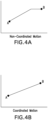
- Figures 4 graphically depict motion of an X-Y gantry system.
- the motion illustrated may be commanded in two modes, namely non-coordinated and coordinated motion, as discussed further herein below.
- the X-Y axes motors are simply moved as fast as possible to their defined positions, without coordination between the motors.
- the non-coordinated motion graph of Figure 4A illustrates that the shorter movement reaches position ahead of the longer movement, which thus creates a flat leg at the end of the motion, during which only one motor is moving.
- the illustration of coordinated motion shows that the motors are driven in coordination relative to each other, thereby graphically creating a straight line of movement. More particularly, in the coordinated motion system, if one of the motors slows down, such as due to higher friction or other unexpected loading, then the other motor also slows down to maintain the "straight line motion" graphically depicted in Figure 4B .
- the embodiments may algorithmically treat the heating element in a manner akin to the axes of motion in a coordinated system, such as is shown in Figure 4B . Accordingly, the heater may be controlled in a coordinated fashion with the other axis(es) of motion.
- the embodiments may thus be particularly desirable for low mass hot ends, in which a change in the expected filament rate generates a substantial change in the energy demanded by the nozzle to quickly reach and maintain the optimum operating temperature. Nevertheless, any change or planned change in the extruder velocity or in the X-Y motion for any type of hot end may be subjected to the embodiments.
- the disclosed heater correlation and control algorithm(s) 1190a, 1190c in addition to providing highly expedited heating adjustment based on the kinematics 1190b of the 3D printer, also appreciably enhances the speed at which information is shared and coordinated within the kinematics control 1190b due, in part, to the intimate connection and correlation 1190c between the heater control algorithm 1190a and the kinematic control code 1190b.
- This allows a substantially smaller hysteresis than in the known art between the command of a change in the heater 105 based on the kinematics 1190b, and the time when the heater 105 responds to the thermal command 1190a.
- the heater commands may thus respond at the same rate as the motors in the kinematic control loop in the embodiments.
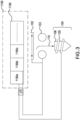
- FIG. 5 illustrates an exemplary heater feedback system 500.
- the feedback to the control algorithm 1190 may be positional information such as may delivered by a sensor 504 associated with the kinematics hardware 506, such as an encoder that tracks motor actuation, and/or may be kinematic information provided directly from control algorithm 1190.
- the feedback 516 from the heater hardware 105 may be converted into a signal that emulates the kinematics positional sensor 504, such as the aforementioned encoder, to the control algorithm 1190.
- the heater hardware 105 may then be driven by output commands 1190a, such as from the I/O of the controller 1100, and such as may be delivered via one or more control signal amplifiers.
- the driver signal(s) 1190a from the controller 1100 may thus be the same or similar to that used to drive the kinematics 506, and thus the heater control 1190a may present to controller 1100 simply as an additional axis within the control algorithm 1190.
- the heater may be controlled by the kinematic control; by the kinematic control, but on its own kinematic algorithm and driver aspects; or by a dedicated heater controller communicative with the kinematic commands. As such, there may or may not be a direct connection between the heater kinematics and the X-Y-Z kinematics.
- FIG. 6 depicts an exemplary computing system 1100 for use as the controller 1100 in association with the herein described systems and methods.
- Computing system 1100 is capable of executing software, such as an operating system (OS) and/or one or more computing applications/algorithms 1190, such as applications/algorithms applying the print plan and control algorithms discussed herein.
- OS operating system
- computing applications/algorithms 1190 such as applications/algorithms applying the print plan and control algorithms discussed herein.
- exemplary computing system 1100 is controlled primarily by computer readable instructions, such as instructions stored in a computer readable storage medium, such as hard disk drive (HDD) 1115, optical disk (not shown) such as a CD or DVD, solid state drive (not shown) such as a USB “thumb drive,” or the like.
- a computer readable storage medium such as hard disk drive (HDD) 1115, optical disk (not shown) such as a CD or DVD, solid state drive (not shown) such as a USB “thumb drive,” or the like.
- Such instructions may be executed within central processing unit (CPU) 1110 to cause computing system 1100 to perform the operations discussed throughout.
- CPU 1110 is implemented in an integrated circuit called a processor.
- exemplary computing system 1100 is shown to comprise a single CPU 1110, such description is merely illustrative, as computing system 1100 may comprise a plurality of CPUs 1110. Additionally, computing system 1100 may exploit the resources of remote CPUs (not shown), for example, through communications network 1170 or some other data communications means.
- CPU 1110 fetches, decodes, and executes instructions from a computer readable storage medium, such as HDD 1115. Such instructions may be included in software such as an operating system (OS), executable programs, and the like. Information, such as computer instructions and other computer readable data, is transferred between components of computing system 1100 via the system's main data-transfer path.
- the main data-transfer path may use a system bus architecture 1105, although other computer architectures (not shown) can be used, such as architectures using serializers and deserializers and crossbar switches to communicate data between devices over serial communication paths.
- System bus 1105 may include data lines for sending data, address lines for sending addresses, and control lines for sending interrupts and for operating the system bus. Some busses provide bus arbitration that regulates access to the bus by extension cards, controllers, and CPU 1110.
- Memory devices coupled to system bus 1105 may include random access memory (RAM) 1125 and/or read only memory (ROM) 1130. Such memories include circuitry that allows information to be stored and retrieved. ROMs 1130 generally contain stored data that cannot be modified. Data stored in RAM 1125 can be read or changed by CPU 1110 or other hardware devices. Access to RAM 1125 and/or ROM 1130 may be controlled by memory controller 1120. Memory controller 1120 may provide an address translation function that translates virtual addresses into physical addresses as instructions are executed. Memory controller 1120 may also provide a memory protection function that isolates processes within the system and isolates system processes from user processes. Thus, a program running in user mode may normally access only memory mapped by its own process virtual address space; in such instances, the program cannot access memory within another process' virtual address space unless memory sharing between the processes has been set up.
- RAM random access memory
- ROM read only memory
- Such memories include circuitry that allows information to be stored and retrieved. ROMs 1130 generally contain stored data that cannot be modified. Data stored in RAM 1125 can
- computing system 1100 may contain peripheral communications bus 135, which is responsible for communicating instructions from CPU 1110 to, and/or receiving data from, peripherals, such as peripherals 1140, 1145, and 1150, which may include printers, keyboards, and/or the sensors, encoders, and the like discussed herein throughout.
- peripherals such as peripherals 1140, 1145, and 1150
- PCI Peripheral Component Interconnect
- Display 1160 which is controlled by display controller 1155, may be used to display visual output and/or presentation generated by or at the request of computing system 1100, responsive to operation of the aforementioned computing program. Such visual output may include text, graphics, animated graphics, and/or video, for example.
- Display 1160 may be implemented with a CRT-based video display, an LCD or LED-based display, a gas plasma-based flat-panel display, a touch-panel display, or the like.
- Display controller 1155 includes electronic components required to generate a video signal that is sent to display 1160.
- computing system 1100 may contain network adapter 1165 which may be used to couple computing system 1100 to external communication network 1170, which may include or provide access to the Internet, an intranet, an extranet, or the like.
- Communications network 1170 may provide user access for computing system 1100 with means of communicating and transferring software and information electronically.
- communications network 1170 may provide for distributed processing, which involves several computers and the sharing of workloads or cooperative efforts in performing a task. It is appreciated that the network connections shown are exemplary and other means of establishing communications links between computing system 1100 and remote users may be used.
- Network adaptor 1165 may communicate to and from network 1170 using any available wired or wireless technologies. Such technologies may include, by way of non-limiting example, cellular, Wi-Fi, Bluetooth, infrared, or the like.
- exemplary computing system 1100 is merely illustrative of a computing environment in which the herein described systems and methods may operate, and does not limit the implementation of the herein described systems and methods in computing environments having differing components and configurations. That is to say, the concepts described herein may be implemented in various computing environments using various components and configurations.
Landscapes
- Chemical & Material Sciences (AREA)
- Engineering & Computer Science (AREA)
- Materials Engineering (AREA)
- Manufacturing & Machinery (AREA)
- Physics & Mathematics (AREA)
- Mechanical Engineering (AREA)
- Optics & Photonics (AREA)
Claims (15)
- System zur generativen Fertigung, das Folgendes umfasst:eine Druckdüse (106), die konfiguriert ist, um zumindest teilweise verflüssigtes Druckmaterial (110) zu liefern, um einen Druckaufbau (111) zu bilden, der auf eine Bewegungssteuerung der Druckdüse (106) in mindestens zwei Achsen durch eine kinematische Steuerung (1100) reagiert;mindestens eine Heizvorrichtung (105) um die Druckdüse (106) herum, die konfiguriert ist, um die zumindest teilweise Verflüssigung des zumindest teilweise verflüssigten Druckmaterials (110) zu bewirken; dadurch gekennzeichnet, dass das System zur generativen Fertigung ferner umfassteine korrelative Schnittstelle zwischen der kinematischen Steuerung (1100) und der mindestens einen Heizvorrichtung (105), wobei die korrelative Schnittstelle kommende Bewegungssteuerungen der Bewegungssteuerung überwacht, um die mindestens eine Heizvorrichtung (105) entsprechend den kommenden Bewegungssteuerungen der Bewegungssteuerung vorausschauend zu betätigen.
- System nach Anspruch 1, das ferner einen Extruder (103) umfasst, der das Druckmaterial (110) gemäß der Steuerung durch die kinematische Steuerung (1100) der Druckdüse (106) zuführt.
- System nach Anspruch 2, wobei die Vorschubgeschwindigkeit des Extruders (103) eine Bewegungssteuerung umfasst.
- System nach Anspruch 3, wobei die Vorschubgeschwindigkeit eine Beschleunigung oder eine Verlangsamung der Vorschubgeschwindigkeit umfasst, wobei eine Beschleunigung einem Anstieg der Wärme von der mindestens einen Heizvorrichtung (105) entspricht.
- System nach Anspruch 1, wobei die korrelative Schnittstelle ein thermisches Profil für eine Vielzahl von möglichen Kombinationen der Heizvorrichtung (105) und der Druckdüse (106) umfasst.
- System nach Anspruch 5, wobei das thermische Profil eine Hysterese aufweist, oder wobei die vorausschauende Betätigung eine Wärmerampenzeit und einen Wärmegrad aufweist, die zumindest teilweise durch das thermische Profil angezeigt werden.
- System nach Anspruch 1, wobei die vorausschauende Betätigung von ungünstigen Bedingungen der Bewegungssteuerung abhängt.
- System nach Anspruch 7, wobei die ungünstige Bedingung eine Verzögerung bei der Lieferung von Druckfilament (110) umfasst, oder wobei die ungünstige Bedingung einen Widerstand bei der Lieferung von Druckfilament (110) umfasst.
- System nach Anspruch 1, wobei die korrelative Schnittstelle eine Kinematik-Hardware (506) umfasst, und wobei die Kinematik-Hardware (506) ein Gantry umfasst.
- System nach Anspruch 1, wobei die Bewegungssteuerung in mindestens drei Achsen erfolgt.
- System nach Anspruch 1, wobei die korrelative Schnittstelle eine Schnittstelle für koordinierte Bewegungen umfasst.
- System nach Anspruch 1, wobei die korrelative Schnittstelle ferner eine eigene Heizvorrichtungssteuerung für die mindestens eine Heizvorrichtung (105) umfasst.
- System nach Anspruch 1, wobei die mindestens eine Heizvorrichtung (105) und die Druckdüse (106) eine geringe thermische Masse aufweisen.
- System nach Anspruch 1, wobei die korrelative Schnittstelle außerdem eine Rückkopplungsschleife umfasst.
- das System nach Anspruch 14, wobei die Rückkopplungsschleifen mindestens einen Sensor (504) umfassen, der der Druckdüse (106) zugeordnet ist, und wobei der Sensor (504) einen Encoder umfasst, der einem Motor (109) zugeordnet ist, der die Druckdüse (106) in den mindestens zwei Achsen bewegen kann.
Priority Applications (1)
| Application Number | Priority Date | Filing Date | Title |
|---|---|---|---|
| EP23204522.9A EP4306298A1 (de) | 2018-12-19 | 2019-12-17 | System zur kinematischen heizung eines druckfilaments zur generativen fertigung |
Applications Claiming Priority (2)
| Application Number | Priority Date | Filing Date | Title |
|---|---|---|---|
| US201862782185P | 2018-12-19 | 2018-12-19 | |
| PCT/US2019/066779 WO2020131830A1 (en) | 2018-12-19 | 2019-12-17 | Apparatus, system and method for kinematic-based heating of an additive manufacturing print filament |
Related Child Applications (1)
| Application Number | Title | Priority Date | Filing Date |
|---|---|---|---|
| EP23204522.9A Division EP4306298A1 (de) | 2018-12-19 | 2019-12-17 | System zur kinematischen heizung eines druckfilaments zur generativen fertigung |
Publications (3)
| Publication Number | Publication Date |
|---|---|
| EP3898192A1 EP3898192A1 (de) | 2021-10-27 |
| EP3898192A4 EP3898192A4 (de) | 2022-01-19 |
| EP3898192B1 true EP3898192B1 (de) | 2023-11-01 |
Family
ID=71102825
Family Applications (2)
| Application Number | Title | Priority Date | Filing Date |
|---|---|---|---|
| EP19900166.0A Active EP3898192B1 (de) | 2018-12-19 | 2019-12-17 | System zur kinematografischen erwärmung eines druckfilaments für die generative fertigung |
| EP23204522.9A Withdrawn EP4306298A1 (de) | 2018-12-19 | 2019-12-17 | System zur kinematischen heizung eines druckfilaments zur generativen fertigung |
Family Applications After (1)
| Application Number | Title | Priority Date | Filing Date |
|---|---|---|---|
| EP23204522.9A Withdrawn EP4306298A1 (de) | 2018-12-19 | 2019-12-17 | System zur kinematischen heizung eines druckfilaments zur generativen fertigung |
Country Status (5)
| Country | Link |
|---|---|
| US (2) | US12208568B2 (de) |
| EP (2) | EP3898192B1 (de) |
| CN (1) | CN113316512B (de) |
| IL (1) | IL284240B2 (de) |
| WO (1) | WO2020131830A1 (de) |
Families Citing this family (2)
| Publication number | Priority date | Publication date | Assignee | Title |
|---|---|---|---|---|
| US11065811B2 (en) | 2019-03-20 | 2021-07-20 | Essentium, Inc. | Three-dimensional printer head including an automatic touchdown apparatus |
| EP4015195A1 (de) * | 2020-12-18 | 2022-06-22 | Bond High Performance 3D Technology B.V. | Extrusionsbasierte generative fertigung 3d-drucksystem und -verfahren |
Family Cites Families (33)
| Publication number | Priority date | Publication date | Assignee | Title |
|---|---|---|---|---|
| US6866807B2 (en) | 2001-09-21 | 2005-03-15 | Stratasys, Inc. | High-precision modeling filament |
| KR101440479B1 (ko) * | 2012-08-08 | 2014-09-17 | 경남대학교 산학협력단 | 신규한 플라니오스타틴 화합물 및 그를 유효성분으로 포함하는 조성물 |
| US20140232035A1 (en) | 2013-02-19 | 2014-08-21 | Hemant Bheda | Reinforced fused-deposition modeling |
| CA3121870A1 (en) * | 2013-03-22 | 2014-09-25 | Markforged, Inc. | Three dimensional printing |
| US9579851B2 (en) | 2013-03-22 | 2017-02-28 | Markforged, Inc. | Apparatus for fiber reinforced additive manufacturing |
| US9186846B1 (en) | 2013-03-22 | 2015-11-17 | Markforged, Inc. | Methods for composite filament threading in three dimensional printing |
| CN103331840B (zh) * | 2013-06-05 | 2015-10-14 | 吴江中瑞机电科技有限公司 | 一种三维打印机树脂材料送丝机构 |
| US20150183164A1 (en) * | 2013-12-30 | 2015-07-02 | Chad E. Duty | Rapid electro-magnetic heating of nozzle in polymer extrusion based deposition for additive manufacturing |
| WO2015189661A1 (en) * | 2014-06-12 | 2015-12-17 | Rhombus International Technologies Limited | Extruder for fused filament fabrication 3d printer |
| CN106794626B (zh) * | 2014-09-26 | 2019-08-27 | 斯特塔思有限公司 | 用于增材制造系统的液化器组件及其使用方法 |
| NL2014044B9 (en) * | 2014-12-23 | 2017-03-29 | Bond High Performance 3D Tech B V | Deposition print head. |
| US20160271876A1 (en) * | 2015-03-22 | 2016-09-22 | Robert Bruce Lower | Apparatus and method of embedding cable in 3D printed objects |
| AT516839B1 (de) * | 2015-05-06 | 2016-09-15 | Headlight Analytics E U | Vorrichtung und Verfahren zur Bildung eines dreidimensionalen Objektes |
| DE102015213011A1 (de) | 2015-07-10 | 2017-01-12 | Eos Gmbh Electro Optical Systems | Verfahren und Vorrichtung zum Herstellen eines dreidimensionalen Objekts |
| US10562227B2 (en) * | 2015-12-01 | 2020-02-18 | Massachusetts Institute Of Technology | Systems, devices, and methods for high-throughput three-dimensional printing |
| US20170182560A1 (en) | 2015-12-16 | 2017-06-29 | Desktop Metal, Inc. | Removable support structure with an interface formed by crystallization of bulk metallic glass |
| CN105666876B (zh) | 2016-03-01 | 2018-01-05 | 西安交通大学 | 一种流体循环控温熔融沉积成形打印头 |
| WO2017189904A1 (en) * | 2016-04-27 | 2017-11-02 | Sabic-Gapt | 3d printer with independent multi zone temperature controller |
| US10328637B2 (en) * | 2016-05-17 | 2019-06-25 | Xerox Corporation | Interlayer adhesion in a part printed by additive manufacturing |
| IL264629B2 (en) * | 2016-08-05 | 2024-11-01 | Jabil Inc | Device, system and method for forming print nozzles for melt layering of materials |
| US10254499B1 (en) * | 2016-08-05 | 2019-04-09 | Southern Methodist University | Additive manufacturing of active devices using dielectric, conductive and magnetic materials |
| JP6843968B2 (ja) | 2016-08-22 | 2021-03-17 | ストラタシス,インコーポレイテッド | 多軸ロボットビルドシステムを用いて3d部品を印刷する方法及び部品のオーブン外3d印刷の方法 |
| CN210453777U (zh) * | 2016-08-23 | 2020-05-05 | 斯特塔思有限公司 | 一种用于以逐层方式打印3d部件的增材制造系统 |
| IT201600103343A1 (it) * | 2016-10-14 | 2018-04-14 | Prima Ind Spa | Macchina operatrice laser per la produzione additiva tramite trattamento termico laser, in particolare fusione, e relativo procedimento |
| US20210187850A1 (en) * | 2016-11-21 | 2021-06-24 | Hewlett-Packard Development Company, L.P. | Heating element assembly |
| US9919430B1 (en) * | 2016-12-06 | 2018-03-20 | Jabil Inc. | Apparatus, system and method for providing an end effector |
| DE102016226322A1 (de) | 2016-12-29 | 2018-07-05 | Eos Gmbh Electro Optical Systems | Verfahren und Vorrichtung zum generativen Herstellen eines dreidimensionalen Objekts |
| WO2018191266A1 (en) * | 2017-04-14 | 2018-10-18 | Desktop Metal, Inc. | Method and apparatus for determining extrudate flow in three-dimensional (3d) pringting |
| CN110325348B (zh) * | 2017-04-20 | 2023-03-14 | 惠普发展公司,有限责任合伙企业 | 预加热三维(3d)打印机构建材料 |
| JP2020521653A (ja) * | 2017-05-30 | 2020-07-27 | シグニファイ ホールディング ビー ヴィSignify Holding B.V. | 一様でないフィラメントを印刷するための力フィードバックを備えるfdmプリンタ及び方法 |
| CN107116220A (zh) | 2017-06-30 | 2017-09-01 | 青岛理工大学 | 一种电场驱动熔融金属喷射沉积3d打印装置及其工作方法 |
| US10419635B1 (en) * | 2018-05-17 | 2019-09-17 | Hewlett-Packard Development Company, L.P. | Printhead temperature control |
| US10780635B1 (en) * | 2019-10-08 | 2020-09-22 | Thermwood Corporation | Apparatus and method for thermal compensation during additive manufacturing |
-
2019
- 2019-12-17 EP EP19900166.0A patent/EP3898192B1/de active Active
- 2019-12-17 CN CN201980088574.XA patent/CN113316512B/zh active Active
- 2019-12-17 WO PCT/US2019/066779 patent/WO2020131830A1/en not_active Ceased
- 2019-12-17 EP EP23204522.9A patent/EP4306298A1/de not_active Withdrawn
- 2019-12-17 US US17/417,039 patent/US12208568B2/en active Active
- 2019-12-17 IL IL284240A patent/IL284240B2/en unknown
-
2024
- 2024-12-06 US US18/971,692 patent/US20250178274A1/en active Pending
Also Published As
| Publication number | Publication date |
|---|---|
| IL284240B2 (en) | 2024-10-01 |
| IL284240B1 (en) | 2024-06-01 |
| IL284240A (en) | 2021-08-31 |
| US20220072766A1 (en) | 2022-03-10 |
| CN113316512B (zh) | 2023-05-30 |
| US20250178274A1 (en) | 2025-06-05 |
| EP3898192A1 (de) | 2021-10-27 |
| EP3898192A4 (de) | 2022-01-19 |
| EP4306298A1 (de) | 2024-01-17 |
| CN113316512A (zh) | 2021-08-27 |
| US12208568B2 (en) | 2025-01-28 |
| WO2020131830A1 (en) | 2020-06-25 |
Similar Documents
| Publication | Publication Date | Title |
|---|---|---|
| US20250178274A1 (en) | Apparatus, system and method for kinematic-based heating of an additive manufacturing print filament | |
| US11969948B2 (en) | Apparatus, system and method of process monitoring and control in an additive manufacturing environment | |
| US20240042678A1 (en) | Apparatus, system and method for plug clearing in an additive manufacturing print head | |
| US20260034726A1 (en) | Apparatus, system and method of providing dynamic hob pinch force in an additive manufacturing print head | |
| US12459199B2 (en) | Apparatus, system and method of providing dynamic hob pinch force in an additive manufacturing print head | |
| US20230405929A1 (en) | Apparatus, system and method for digitally masked print area heating | |
| CN113302036A (zh) | 用于混合增材制造喷嘴的设备、系统和方法 |
Legal Events
| Date | Code | Title | Description |
|---|---|---|---|
| STAA | Information on the status of an ep patent application or granted ep patent |
Free format text: STATUS: THE INTERNATIONAL PUBLICATION HAS BEEN MADE |
|
| PUAI | Public reference made under article 153(3) epc to a published international application that has entered the european phase |
Free format text: ORIGINAL CODE: 0009012 |
|
| STAA | Information on the status of an ep patent application or granted ep patent |
Free format text: STATUS: REQUEST FOR EXAMINATION WAS MADE |
|
| 17P | Request for examination filed |
Effective date: 20210716 |
|
| AK | Designated contracting states |
Kind code of ref document: A1 Designated state(s): AL AT BE BG CH CY CZ DE DK EE ES FI FR GB GR HR HU IE IS IT LI LT LU LV MC MK MT NL NO PL PT RO RS SE SI SK SM TR |
|
| A4 | Supplementary search report drawn up and despatched |
Effective date: 20211222 |
|
| RIC1 | Information provided on ipc code assigned before grant |
Ipc: B33Y 50/00 20150101ALI20211216BHEP Ipc: B33Y 30/00 20150101ALI20211216BHEP Ipc: B29C 64/118 20170101ALI20211216BHEP Ipc: B29C 64/393 20170101ALI20211216BHEP Ipc: B29C 64/386 20170101ALI20211216BHEP Ipc: B29C 64/295 20170101ALI20211216BHEP Ipc: B29C 64/209 20170101AFI20211216BHEP |
|
| DAV | Request for validation of the european patent (deleted) | ||
| DAX | Request for extension of the european patent (deleted) | ||
| GRAP | Despatch of communication of intention to grant a patent |
Free format text: ORIGINAL CODE: EPIDOSNIGR1 |
|
| STAA | Information on the status of an ep patent application or granted ep patent |
Free format text: STATUS: GRANT OF PATENT IS INTENDED |
|
| RIC1 | Information provided on ipc code assigned before grant |
Ipc: B29C 64/106 20170101ALI20230721BHEP Ipc: B33Y 50/00 20150101ALI20230721BHEP Ipc: B33Y 30/00 20150101ALI20230721BHEP Ipc: B29C 64/118 20170101ALI20230721BHEP Ipc: B29C 64/393 20170101ALI20230721BHEP Ipc: B29C 64/386 20170101ALI20230721BHEP Ipc: B29C 64/295 20170101ALI20230721BHEP Ipc: B29C 64/209 20170101AFI20230721BHEP |
|
| INTG | Intention to grant announced |
Effective date: 20230808 |
|
| GRAS | Grant fee paid |
Free format text: ORIGINAL CODE: EPIDOSNIGR3 |
|
| GRAA | (expected) grant |
Free format text: ORIGINAL CODE: 0009210 |
|
| STAA | Information on the status of an ep patent application or granted ep patent |
Free format text: STATUS: THE PATENT HAS BEEN GRANTED |
|
| AK | Designated contracting states |
Kind code of ref document: B1 Designated state(s): AL AT BE BG CH CY CZ DE DK EE ES FI FR GB GR HR HU IE IS IT LI LT LU LV MC MK MT NL NO PL PT RO RS SE SI SK SM TR |
|
| REG | Reference to a national code |
Ref country code: GB Ref legal event code: FG4D |
|
| REG | Reference to a national code |
Ref country code: CH Ref legal event code: EP |
|
| REG | Reference to a national code |
Ref country code: DE Ref legal event code: R096 Ref document number: 602019040837 Country of ref document: DE |
|
| REG | Reference to a national code |
Ref country code: IE Ref legal event code: FG4D |
|
| P01 | Opt-out of the competence of the unified patent court (upc) registered |
Effective date: 20231201 |
|
| REG | Reference to a national code |
Ref country code: LT Ref legal event code: MG9D |
|
| REG | Reference to a national code |
Ref country code: NL Ref legal event code: MP Effective date: 20231101 |
|
| PG25 | Lapsed in a contracting state [announced via postgrant information from national office to epo] |
Ref country code: GR Free format text: LAPSE BECAUSE OF FAILURE TO SUBMIT A TRANSLATION OF THE DESCRIPTION OR TO PAY THE FEE WITHIN THE PRESCRIBED TIME-LIMIT Effective date: 20240202 |
|
| PG25 | Lapsed in a contracting state [announced via postgrant information from national office to epo] |
Ref country code: IS Free format text: LAPSE BECAUSE OF FAILURE TO SUBMIT A TRANSLATION OF THE DESCRIPTION OR TO PAY THE FEE WITHIN THE PRESCRIBED TIME-LIMIT Effective date: 20240301 |
|
| PG25 | Lapsed in a contracting state [announced via postgrant information from national office to epo] |
Ref country code: LT Free format text: LAPSE BECAUSE OF FAILURE TO SUBMIT A TRANSLATION OF THE DESCRIPTION OR TO PAY THE FEE WITHIN THE PRESCRIBED TIME-LIMIT Effective date: 20231101 |
|
| REG | Reference to a national code |
Ref country code: AT Ref legal event code: MK05 Ref document number: 1626735 Country of ref document: AT Kind code of ref document: T Effective date: 20231101 |
|
| PG25 | Lapsed in a contracting state [announced via postgrant information from national office to epo] |
Ref country code: NL Free format text: LAPSE BECAUSE OF FAILURE TO SUBMIT A TRANSLATION OF THE DESCRIPTION OR TO PAY THE FEE WITHIN THE PRESCRIBED TIME-LIMIT Effective date: 20231101 |
|
| PG25 | Lapsed in a contracting state [announced via postgrant information from national office to epo] |
Ref country code: AT Free format text: LAPSE BECAUSE OF FAILURE TO SUBMIT A TRANSLATION OF THE DESCRIPTION OR TO PAY THE FEE WITHIN THE PRESCRIBED TIME-LIMIT Effective date: 20231101 |
|
| PG25 | Lapsed in a contracting state [announced via postgrant information from national office to epo] |
Ref country code: ES Free format text: LAPSE BECAUSE OF FAILURE TO SUBMIT A TRANSLATION OF THE DESCRIPTION OR TO PAY THE FEE WITHIN THE PRESCRIBED TIME-LIMIT Effective date: 20231101 |
|
| PG25 | Lapsed in a contracting state [announced via postgrant information from national office to epo] |
Ref country code: NL Free format text: LAPSE BECAUSE OF FAILURE TO SUBMIT A TRANSLATION OF THE DESCRIPTION OR TO PAY THE FEE WITHIN THE PRESCRIBED TIME-LIMIT Effective date: 20231101 Ref country code: LT Free format text: LAPSE BECAUSE OF FAILURE TO SUBMIT A TRANSLATION OF THE DESCRIPTION OR TO PAY THE FEE WITHIN THE PRESCRIBED TIME-LIMIT Effective date: 20231101 Ref country code: IS Free format text: LAPSE BECAUSE OF FAILURE TO SUBMIT A TRANSLATION OF THE DESCRIPTION OR TO PAY THE FEE WITHIN THE PRESCRIBED TIME-LIMIT Effective date: 20240301 Ref country code: GR Free format text: LAPSE BECAUSE OF FAILURE TO SUBMIT A TRANSLATION OF THE DESCRIPTION OR TO PAY THE FEE WITHIN THE PRESCRIBED TIME-LIMIT Effective date: 20240202 Ref country code: ES Free format text: LAPSE BECAUSE OF FAILURE TO SUBMIT A TRANSLATION OF THE DESCRIPTION OR TO PAY THE FEE WITHIN THE PRESCRIBED TIME-LIMIT Effective date: 20231101 Ref country code: BG Free format text: LAPSE BECAUSE OF FAILURE TO SUBMIT A TRANSLATION OF THE DESCRIPTION OR TO PAY THE FEE WITHIN THE PRESCRIBED TIME-LIMIT Effective date: 20240201 Ref country code: AT Free format text: LAPSE BECAUSE OF FAILURE TO SUBMIT A TRANSLATION OF THE DESCRIPTION OR TO PAY THE FEE WITHIN THE PRESCRIBED TIME-LIMIT Effective date: 20231101 Ref country code: PT Free format text: LAPSE BECAUSE OF FAILURE TO SUBMIT A TRANSLATION OF THE DESCRIPTION OR TO PAY THE FEE WITHIN THE PRESCRIBED TIME-LIMIT Effective date: 20240301 |
|
| PG25 | Lapsed in a contracting state [announced via postgrant information from national office to epo] |
Ref country code: SE Free format text: LAPSE BECAUSE OF FAILURE TO SUBMIT A TRANSLATION OF THE DESCRIPTION OR TO PAY THE FEE WITHIN THE PRESCRIBED TIME-LIMIT Effective date: 20231101 Ref country code: RS Free format text: LAPSE BECAUSE OF FAILURE TO SUBMIT A TRANSLATION OF THE DESCRIPTION OR TO PAY THE FEE WITHIN THE PRESCRIBED TIME-LIMIT Effective date: 20231101 Ref country code: PL Free format text: LAPSE BECAUSE OF FAILURE TO SUBMIT A TRANSLATION OF THE DESCRIPTION OR TO PAY THE FEE WITHIN THE PRESCRIBED TIME-LIMIT Effective date: 20231101 Ref country code: NO Free format text: LAPSE BECAUSE OF FAILURE TO SUBMIT A TRANSLATION OF THE DESCRIPTION OR TO PAY THE FEE WITHIN THE PRESCRIBED TIME-LIMIT Effective date: 20240201 Ref country code: LV Free format text: LAPSE BECAUSE OF FAILURE TO SUBMIT A TRANSLATION OF THE DESCRIPTION OR TO PAY THE FEE WITHIN THE PRESCRIBED TIME-LIMIT Effective date: 20231101 Ref country code: HR Free format text: LAPSE BECAUSE OF FAILURE TO SUBMIT A TRANSLATION OF THE DESCRIPTION OR TO PAY THE FEE WITHIN THE PRESCRIBED TIME-LIMIT Effective date: 20231101 |
|
| PG25 | Lapsed in a contracting state [announced via postgrant information from national office to epo] |
Ref country code: DK Free format text: LAPSE BECAUSE OF FAILURE TO SUBMIT A TRANSLATION OF THE DESCRIPTION OR TO PAY THE FEE WITHIN THE PRESCRIBED TIME-LIMIT Effective date: 20231101 |
|
| PG25 | Lapsed in a contracting state [announced via postgrant information from national office to epo] |
Ref country code: CZ Free format text: LAPSE BECAUSE OF FAILURE TO SUBMIT A TRANSLATION OF THE DESCRIPTION OR TO PAY THE FEE WITHIN THE PRESCRIBED TIME-LIMIT Effective date: 20231101 |
|
| PG25 | Lapsed in a contracting state [announced via postgrant information from national office to epo] |
Ref country code: SK Free format text: LAPSE BECAUSE OF FAILURE TO SUBMIT A TRANSLATION OF THE DESCRIPTION OR TO PAY THE FEE WITHIN THE PRESCRIBED TIME-LIMIT Effective date: 20231101 |
|
| PG25 | Lapsed in a contracting state [announced via postgrant information from national office to epo] |
Ref country code: SM Free format text: LAPSE BECAUSE OF FAILURE TO SUBMIT A TRANSLATION OF THE DESCRIPTION OR TO PAY THE FEE WITHIN THE PRESCRIBED TIME-LIMIT Effective date: 20231101 Ref country code: SK Free format text: LAPSE BECAUSE OF FAILURE TO SUBMIT A TRANSLATION OF THE DESCRIPTION OR TO PAY THE FEE WITHIN THE PRESCRIBED TIME-LIMIT Effective date: 20231101 Ref country code: IT Free format text: LAPSE BECAUSE OF FAILURE TO SUBMIT A TRANSLATION OF THE DESCRIPTION OR TO PAY THE FEE WITHIN THE PRESCRIBED TIME-LIMIT Effective date: 20231101 Ref country code: EE Free format text: LAPSE BECAUSE OF FAILURE TO SUBMIT A TRANSLATION OF THE DESCRIPTION OR TO PAY THE FEE WITHIN THE PRESCRIBED TIME-LIMIT Effective date: 20231101 Ref country code: DK Free format text: LAPSE BECAUSE OF FAILURE TO SUBMIT A TRANSLATION OF THE DESCRIPTION OR TO PAY THE FEE WITHIN THE PRESCRIBED TIME-LIMIT Effective date: 20231101 Ref country code: CZ Free format text: LAPSE BECAUSE OF FAILURE TO SUBMIT A TRANSLATION OF THE DESCRIPTION OR TO PAY THE FEE WITHIN THE PRESCRIBED TIME-LIMIT Effective date: 20231101 |
|
| REG | Reference to a national code |
Ref country code: CH Ref legal event code: PL |
|
| REG | Reference to a national code |
Ref country code: DE Ref legal event code: R097 Ref document number: 602019040837 Country of ref document: DE |
|
| PG25 | Lapsed in a contracting state [announced via postgrant information from national office to epo] |
Ref country code: LU Free format text: LAPSE BECAUSE OF NON-PAYMENT OF DUE FEES Effective date: 20231217 |
|
| PG25 | Lapsed in a contracting state [announced via postgrant information from national office to epo] |
Ref country code: MC Free format text: LAPSE BECAUSE OF FAILURE TO SUBMIT A TRANSLATION OF THE DESCRIPTION OR TO PAY THE FEE WITHIN THE PRESCRIBED TIME-LIMIT Effective date: 20231101 |
|
| REG | Reference to a national code |
Ref country code: BE Ref legal event code: MM Effective date: 20231231 |
|
| PG25 | Lapsed in a contracting state [announced via postgrant information from national office to epo] |
Ref country code: MC Free format text: LAPSE BECAUSE OF FAILURE TO SUBMIT A TRANSLATION OF THE DESCRIPTION OR TO PAY THE FEE WITHIN THE PRESCRIBED TIME-LIMIT Effective date: 20231101 Ref country code: LU Free format text: LAPSE BECAUSE OF NON-PAYMENT OF DUE FEES Effective date: 20231217 |
|
| PLBE | No opposition filed within time limit |
Free format text: ORIGINAL CODE: 0009261 |
|
| STAA | Information on the status of an ep patent application or granted ep patent |
Free format text: STATUS: NO OPPOSITION FILED WITHIN TIME LIMIT |
|
| 26N | No opposition filed |
Effective date: 20240802 |
|
| REG | Reference to a national code |
Ref country code: IE Ref legal event code: MM4A |
|
| PG25 | Lapsed in a contracting state [announced via postgrant information from national office to epo] |
Ref country code: IE Free format text: LAPSE BECAUSE OF NON-PAYMENT OF DUE FEES Effective date: 20231217 |
|
| PG25 | Lapsed in a contracting state [announced via postgrant information from national office to epo] |
Ref country code: BE Free format text: LAPSE BECAUSE OF NON-PAYMENT OF DUE FEES Effective date: 20231231 |
|
| PG25 | Lapsed in a contracting state [announced via postgrant information from national office to epo] |
Ref country code: CH Free format text: LAPSE BECAUSE OF NON-PAYMENT OF DUE FEES Effective date: 20231231 |
|
| PG25 | Lapsed in a contracting state [announced via postgrant information from national office to epo] |
Ref country code: SI Free format text: LAPSE BECAUSE OF FAILURE TO SUBMIT A TRANSLATION OF THE DESCRIPTION OR TO PAY THE FEE WITHIN THE PRESCRIBED TIME-LIMIT Effective date: 20231101 |
|
| PG25 | Lapsed in a contracting state [announced via postgrant information from national office to epo] |
Ref country code: SI Free format text: LAPSE BECAUSE OF FAILURE TO SUBMIT A TRANSLATION OF THE DESCRIPTION OR TO PAY THE FEE WITHIN THE PRESCRIBED TIME-LIMIT Effective date: 20231101 Ref country code: IE Free format text: LAPSE BECAUSE OF NON-PAYMENT OF DUE FEES Effective date: 20231217 Ref country code: CH Free format text: LAPSE BECAUSE OF NON-PAYMENT OF DUE FEES Effective date: 20231231 Ref country code: BE Free format text: LAPSE BECAUSE OF NON-PAYMENT OF DUE FEES Effective date: 20231231 |
|
| PGFP | Annual fee paid to national office [announced via postgrant information from national office to epo] |
Ref country code: DE Payment date: 20241216 Year of fee payment: 6 |
|
| PGFP | Annual fee paid to national office [announced via postgrant information from national office to epo] |
Ref country code: GB Payment date: 20241218 Year of fee payment: 6 |
|
| PGFP | Annual fee paid to national office [announced via postgrant information from national office to epo] |
Ref country code: FR Payment date: 20241217 Year of fee payment: 6 |
|
| PG25 | Lapsed in a contracting state [announced via postgrant information from national office to epo] |
Ref country code: RO Free format text: LAPSE BECAUSE OF FAILURE TO SUBMIT A TRANSLATION OF THE DESCRIPTION OR TO PAY THE FEE WITHIN THE PRESCRIBED TIME-LIMIT Effective date: 20231101 |
|
| PG25 | Lapsed in a contracting state [announced via postgrant information from national office to epo] |
Ref country code: FI Free format text: LAPSE BECAUSE OF FAILURE TO SUBMIT A TRANSLATION OF THE DESCRIPTION OR TO PAY THE FEE WITHIN THE PRESCRIBED TIME-LIMIT Effective date: 20231101 |
|
| PG25 | Lapsed in a contracting state [announced via postgrant information from national office to epo] |
Ref country code: CY Free format text: LAPSE BECAUSE OF FAILURE TO SUBMIT A TRANSLATION OF THE DESCRIPTION OR TO PAY THE FEE WITHIN THE PRESCRIBED TIME-LIMIT; INVALID AB INITIO Effective date: 20191217 |
|
| PG25 | Lapsed in a contracting state [announced via postgrant information from national office to epo] |
Ref country code: HU Free format text: LAPSE BECAUSE OF FAILURE TO SUBMIT A TRANSLATION OF THE DESCRIPTION OR TO PAY THE FEE WITHIN THE PRESCRIBED TIME-LIMIT; INVALID AB INITIO Effective date: 20191217 |
|
| PG25 | Lapsed in a contracting state [announced via postgrant information from national office to epo] |
Ref country code: TR Free format text: LAPSE BECAUSE OF FAILURE TO SUBMIT A TRANSLATION OF THE DESCRIPTION OR TO PAY THE FEE WITHIN THE PRESCRIBED TIME-LIMIT Effective date: 20231101 |