EP3898211B1 - Formsegment für reifen mit verbundenen ersten und zweiten lamellenelementen - Google Patents
Formsegment für reifen mit verbundenen ersten und zweiten lamellenelementen Download PDFInfo
- Publication number
- EP3898211B1 EP3898211B1 EP19832458.4A EP19832458A EP3898211B1 EP 3898211 B1 EP3898211 B1 EP 3898211B1 EP 19832458 A EP19832458 A EP 19832458A EP 3898211 B1 EP3898211 B1 EP 3898211B1
- Authority
- EP
- European Patent Office
- Prior art keywords
- sipe element
- sipe
- teardrop
- section
- mold segment
- Prior art date
- Legal status (The legal status is an assumption and is not a legal conclusion. Google has not performed a legal analysis and makes no representation as to the accuracy of the status listed.)
- Active
Links
Images


Classifications
-
- B—PERFORMING OPERATIONS; TRANSPORTING
- B29—WORKING OF PLASTICS; WORKING OF SUBSTANCES IN A PLASTIC STATE IN GENERAL
- B29D—PRODUCING PARTICULAR ARTICLES FROM PLASTICS OR FROM SUBSTANCES IN A PLASTIC STATE
- B29D30/00—Producing pneumatic or solid tyres or parts thereof
- B29D30/06—Pneumatic tyres or parts thereof (e.g. produced by casting, moulding, compression moulding, injection moulding, centrifugal casting)
- B29D30/0601—Vulcanising tyres; Vulcanising presses for tyres
- B29D30/0606—Vulcanising moulds not integral with vulcanising presses
- B29D2030/0607—Constructional features of the moulds
- B29D2030/0613—Means, e.g. sipes or blade-like elements, for forming narrow recesses in the tyres, e.g. cuts or incisions for winter tyres
Definitions
- the present invention relates generally to a mold segment for the formation of tires. More particularly, the present application involves a mold segment that features first and second sipe elements that can be received onto one another to result in a teardrop longitudinal sipe with no or minimized misaligned sections therein.
- the present invention relates to a mold segment according to the preamble of claim 1, such as it is e.g. known from WO 2015/086974 A1 or
- the expandable bladder when inflated and applying force causes the crown portion of the tire to be forced against a garniture of the mold that includes a series of features that form grooves, sipes, and tread blocks of the tire to result in the formation of the tread design of the tire.
- the garniture can be made of two or more multiple sections that are arranged in a circle.
- a production mold segment 74 is shown in Fig. 1 and features that are used to form the architecture of the tread are shown.
- a series of sipe sections are present in the production mold segment 74.
- a first sipe element 94 is located next to a second sipe element 96 which is likewise located next to a third sipe element 98.
- the sipe elements 94, 96, 98 are not completely aligned next to one another.
- a misalignment 100 exists between the first and second sipe elements 94, 96 such that the teardrop forming portions of these elements 94, 96 are out of alignment by the misalignment 100.
- the other portions of the sipe elements 94, 96 can likewise be misaligned, and it is also the case that the portions of the second and third sipe elements 96, 98 are likewise misaligned to one another. Molding of the tire with the misaligned sipe elements 94, 96, 98 causes the resulting teardrop longitudinal sipe in the tire to have sections that are stepped and otherwise misaligned.
- the misalignments may be in the teardrop sections or the narrow portions or both of the teardrop longitudinal sipe. As multiple production mold segments 74 are present in the garniture, if all or a portion of them include misaligned sipe elements then multiple steps and misalignments are present within the final teardrop longitudinal sipe. This may cause poorer hydrodynamical behavior for the tire.
- the casting process employs a gypsum/plaster cast segment that includes the sipe elements 94, 96, 98.
- a flexible cast segment is used and into this flexible cast segment the sipe elements 94, 96, 98 are inserted.
- the sipe elements 94, 96, 98 are aligned next to one another for use in forming the teardrop longitudinal sipe in the tire.
- the sipe elements 94, 96, 98 may not be placed precisely in alignment with one another and their positions may shift during the subsequent casting processes into which the sipe elements 94, 96, 98 are transferred to the gypsum cast segment and the production mold segment 74. Misalignment of the sipe elements 94, 96, 98 in the casting process results in a teardrop longitudinal sipe in the tire that has irregularities. As such, there remains room for variation and improvement within the art.
- a mold segment 10 is provided that has a first sipe element 12 and a second sipe element 20 that feature male and female connectors 26, 18.
- the male and female connectors 26, 18 can be engaged to cause the sipe elements 12, 20 to be connected to one another when placed into the mold segment 10.
- the positions of the sipe elements 12, 20 will be maintained during the different steps of the casting process to keep teardrop sections 16, 24 of the sipe elements 12, 20 aligned so that the resulting production mold segment 74 will have aligned teardrop sipe architecture.
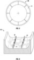
- a tire 42 is illustrated in perspective view that has a central axis 78 that serves as the axis of rotation of the tire 42.
- the central axis 78 extends through the center of the tire 42 and is aligned in the axial direction.
- the radial direction 80 of the tire 42 extends outward from the central axis 78 and is perpendicular to the central axis 78.
- the tire 42 also has a circumferential direction that extends around the circumference of the tire 42 and circles the central axis 78.
- the circumferential direction may be located at any distance from the central axis 78 in the radial direction 80 of the tire 42, and need not be located only at the tread 86 or the outer most portion of the tire 42 in the radial direction 80.
- the tire 42 has tread 86 that may feature various tire architecture such as tread blocks, grooves, sipes, and ribs.
- the tread 86 shown has two teardrop longitudinal sipes 44 that extend around the entire circumference of the tread 86. In this regard, the teardrop longitudinal sipes 44 extend 360 degrees around the central axis 78.
- other tire architecture of the tread shown could include lateral sipes that are located in the three sections formed by the shoulder edges of the tread 86 and the two teardrop longitudinal sipes 44.
- the mold segment 10 that is used to form the tire 42 may be arranged to form only a single teardrop longitudinal sipe 44 in other embodiments.
- the mold segment 10 may be used to form a tire with one or more teardrop longitudinal sipes 44 with any other tread 86 architecture such as additional sipes, grooves, ribs, etc.
- a pair of sidewalls extend from the crown of the tire 42 on either side in the axial direction 78 towards the center in the radial direction 80.
- some features of the tread 86 such as lateral sipes (if present) and grooves, may extend into the sidewalls as well.
- Fig. 4 shows a mold 84 for curing a tire 42.
- a tire 42 that is made of uncured rubber is placed into the mold 84 and cured via heat and pressure applied by the mold 84.
- the mold 84 can be configured in a variety of ways.
- the mold 84 includes a garniture 82 that has a series of production mold segments 74 that engage the tire 42 to form the tread 86 of the tire 42.
- the mold 84 also includes a top mold section 88 and a bottom mold section 90 that engage the sidewalls of the tire 42 and form the sidewall portions.
- additional top and bottom mold sections 88, 90 can be included and thus multiple other components may be present in the mold 84 for forming the tire 42.
- production mold segments 74 are not movable while others are in fact movable to open and close the mold 84.
- the production mold segments 74 may be movable in that they move relative to the ground onto which the mold 84 rests.
- the garniture 82 of the mold 84 is made of a plurality of production mold segments 74 that extend 360 degrees about an axis.
- the production mold segments 74 may be in engagement with one another, or a small space could be present between the production mold segments 74.
- the production mold segments 74 can move in the radial direction towards the central axis to further add pressure to the tire 42 during curing.
- the production mold segments 74 are stationary and do not move in the radial direction.
- the production mold segments 74 can be the same size as one another, or may be different sizes from one another.
- the garniture 82 can include any number of production mold segments 74 in other arrangements. For example, from 9-12 production mold segments 74 can be included in the garniture 82 in other versions of the mold 84. Still further, although described as having production mold segments 74, the garniture 82 could in fact be composed of zero production mold segments 74 in other arrangements in which the garniture 82 is a single, solid piece that extends around its central axis.
- the production mold segments 74 thus engage the tire 42 during formation, and include the various sipe elements such as the first sipe element 12 and the second sipe element 20 that are used to form the teardrop longitudinal sipe 44 of the tire 42 upon molding by the mold 84.
- the mold making process can employ a gypsum cast segment that includes embedded in it sipe making elements and those used to make the teardrop longitudinal sipe 44 such as the first and second sipe elements 12, 20.
- the first and second sipe elements 12, 20 are embedded into the production mold segment 74 so that the teardrop sections 16, 24 are more into the gypsum and the narrow sections 14, 22 extend more out of and away from the gypsum.
- the gypsum cast segment also has various features that are imparted into the production mold segment 74 such as grooves, ribs, and shoulder features.
- the gypsum cast segment is a positive image of the tread 86.
- Hot aluminum is poured onto the gypsum cast segment which then hardens and takes on the features of the gypsum cast segment and the exposed pieces such as the sipe making elements are embedded into the production mold segment 74.
- the narrow sections 14, 22 may be those that are embedded into the production mold segment 74.
- the gypsum may be machined off as desired in order to complete the production mold segment 74.
- the molding process may use a mold segment 10, one example of which is illustrated with reference to Fig. 6 .
- the mold segment 10 has some flexibility in it and may sometimes be referred to as a flexible cast segment 10.
- the mold segment 10 may be made out of castable mold rubber such as polysulfide rubber.
- the mold segment 10 has a mold segment base 28 and it is this base 28 that can include the polysulfide rubber and be somewhat flexible.
- the various features in the mold segment base 28 that form the architecture of the tread 86 can be made out of the flexible material.
- first and second sipe elements 12, 20 can be placed into the mold segment base 28 at this stage of the production process, and these first and second sipe elements 12, 20 may be eventually transferred to the production mold segment 74 and engage the tire 42 to form the teardrop longitudinal sipe 44 during curing.
- the first and second sipe elements 12, 20 are pushed into the flexible mold segment base 28 and held therein by the gripping force of the flexible mold segment base 28.
- the first and second sipe elements 12, 20 are interlocked with one another via a connection described herein so that their position relative to one another remains constant and does not vary during the production process.
- the mold segment 10 features three sipe elements interlocked with one another and pressed into the mold segment base 28. An additional three interlocked sipe elements are next to these three to form the adjacent teardrop longitudinal sipe 44.
- any number of two or more sipe elements can be present in the mold segment base 28.
- the sipe elements can be arranged so that they are interlocked not linearly but instead have some angled arrangement to accommodate some or all of the curvature of the mold segment base 28.
- the sipe elements 12, 20 inserted into the mold segment base 28 may engage it only at the bottom, or various feature forming portions of the mold segment base 28 can touch the sipe elements 12, 20 on their sides as well.
- the sipe elements 12, 20 are arranged into the mold segment base 28 so that narrow sections 14, 22 extend out of the mold segment base 28 and the teardrop sections 16, 24 are farther away from this point of extension.
- Figs. 7-11 illustrate a first sipe element 12 in accordance with one exemplary embodiment.
- the first sipe element 12 can be made out of a rigid material such as steel or aluminum, and may include a relatively flat first sipe element narrow section 14 that is used to form the narrow sipe section of the teardrop longitudinal sipe 44.
- a first sipe element embedded end 46 is present and has a first sipe element void 48.
- the first sipe element embedded end 46 is pressed into the mold segment base 28 and buried therein when forming the mold segment 10, and the first sipe element narrow section 14 can remain exposed.
- the first sipe element void 48 may be dovetail in shape, but can be variously shaped in other exemplary embodiments.
- the first sipe element embedded end 46 may be integrally formed with the first sipe element narrow section 14.
- the first sipe element 12 also includes a first sipe element teardrop section 16 located at an end of the first sipe element narrow section 14.
- the first sipe element teardrop section 16 is the portion of the first sipe element 12 used to form the teardrop portion of the teardrop longitudinal sipe 44 and is wider than the first sipe element narrow section 14.
- the first sipe element teardrop section 16 is offset from the first sipe element narrow section 14 in the length direction, and is not movable relative to the first sipe element narrow section 14.
- the first sipe element 12 has a first terminal end 34 which is the farther portion of the first sipe element 12 in one direction.
- the first sipe element teardrop section 16 is located at the first terminal end 34, and the first sipe element narrow section 14 is not located at the first terminal end 34.
- the first sipe element teardrop section 16 is offset from the first sipe element narrow section 14 such that an offset 36 is measured from the first terminal end 34 to the first sipe element narrow section 14.
- the first sipe element 12 has a first sipe element second terminal end 72 and the first sipe element narrow section 14 is located at the first sipe element second terminal end 72.
- the first sipe element teardrop section 16 is spaced from and is not located at the first sipe element second terminal end 72.
- the offset 36 is one millimeter.
- the second sipe element 20 has a second sipe element embedded end 50 that with a second sipe element narrow section 22 defines a second sipe element void 52.
- the second sipe element teardrop section 24 has a length 70, and in some instances the length 70 is the same as the length of the second sipe element narrow section 22.
- the second sipe element 20 has a first terminal end 38 at which the second sipe element narrow section 22 is located.
- An oppositely disposed second terminal end 58 of the second sipe element 20 is present and the second sipe element teardrop section 24 is located at the second terminal end 58.
- the teardrop sections 16, 24 may be connected to the other portions of the sipe elements 12, 20 by any manner such as crimping, welding, brazing, mechanical fasteners, or integral formation. This connection may be permanent, or it may be a removable connection.
- the second sipe element teardrop section 24 is offset 40 from the first terminal end 38 and the second sipe element teardrop section 24 is not located at the first terminal end 38.
- the second sipe element 20 has a first leg 32 and a second leg 54 that are spaced from one another a distance 56.
- the legs 32, 54 are integrally formed with the second sipe element narrow section 22 and may be of the same width as the second sipe element narrow section 22.
- a void exists between the legs 32, 54 in the length direction.
- the first leg 32 has a length 66 in the longitudinal direction
- the second leg 54 has a length 68 in the longitudinal direction.
- the lengths 66 and 68 may be the same in some embodiments.
- the second sipe element 20 has a male connector 26 located at the first terminal end 38.
- the male connector 26 is composed of the first leg 32 and is that portion of the first leg 32 that is exposed via the offset 40.
- the length 66 must be at a minimum 4 millimeters, and the length 68 must be at a minimum 4 millimeters, and the length 56 between the two legs 32 and 54 must be at least 16 millimeters.
- the offset 40 is one millimeter, and the offset 36 is one millimeter.
- the female connector 18 and male connector 26 can be engaged with one another to lock the position of the first sipe element 12 to the second sipe element 20.
- Fig. 13 shows the two sipe elements 12, 20 moved into engagement with one another so that the female connector 18 engages the male connector 26.
- the elements 12, 20 are described as connected because through their engagement they cannot move in at least some directions such as closer to one another, or to the left or right of one another.
- Engagement of the two sipe elements 12 and 20 allows them to be inserted into the mold segment base 28 so that their relative positions to one another will not change during the mold 84 building process.
- the resulting production mold segment 74 will have features for forming the teardrop longitudinal sipe 44 that are more closely aligned with one another so that steps are eliminated or reduced.
- the connection results from moving the first leg 32 of the second sipe element 20 into the slot 30 of the first sipe element teardrop section 16.
- the first leg 32 is sized relative to the slot 30 so that it is tightly received therein.
- the offset 40 distance is the same as the distance of offset 36 so that the first terminal end 38 engages the first sipe element narrow section 14.
- the second sipe element teardrop section 24 engages the first sipe element teardrop section 16 when the female and male connectors 18, 26 are connected.
- the geometry of the first terminal end 38, the end of the second sipe element teardrop section 24, the first terminal end 34, and/or the first sipe element narrow section 14 can be arranged so that the first and second sipe elements 12, 20 are angled relative to one another when the connectors 18, 26 are engaged as shown in Fig. 13 .
- the geometry can be arranged so that the first and second sipe elements 12, 20 when connected are not angled relative to one another but are parallel to one another.
- the angled arrangement may allow the connected sipe elements 12, 20 to better conform to the concave curvature of the mold segment base 28 when forming the round section of the tire 42.
- Fig. 14 shows the first and second sipe elements 12, 20 connected and parallel to one another when connected.
- the drawing also shows a third sipe element 92 connected and parallel to the first sipe element 12.
- Male and female connectors 26, 18 can be present on opposite ends of the sipe elements so that two sipe elements can be connected thereto.
- the sipe elements can be configured in a variety of different manners in accordance with other embodiments of the mold segment 10.
- the first sipe element narrow section 14 of the first sipe element 12 is shown in Fig. 15 .
- the first sipe element void 48 has a dovetail shape and is at the end of the first sipe element 12 that includes the first sipe element embedded end 46.
- the void 48 need not be dovetail shaped in other embodiments.
- the opposite end includes a pair of the legs as previously discussed that are separated from one another by a distance such that a void is present between the legs.
- the legs are illustrated as being square in shape, they may be rectangular, circular, triangular, or variously shaped in accordance with other exemplary embodiments.
- a variation of the sipe element is shown in Fig.
- the second sipe element 20 is illustrated that features but a single first leg 32. No other legs of the second sipe element 20 are present except for this single first leg 32 of the second sipe element 20.
- the single first leg 32 is located at both terminal ends 38, 58 such that it extends the entire length of the second sipe element 20.
- the second sipe element narrow section 22 likewise is located at the terminal ends 38, 58.
- the second sipe element teardrop section 24 can be retained onto the first leg 32 via any possible mechanism such as crimping, welding, integral formation, or mechanical fasteners.
- the length 70 can be the same as the length of the first leg 32, but the second sipe element teardrop section 24 can be offset from the first leg 32 so that a female connector 18 and male connector 26 are formed. Alternatively, the length 70 can be longer or shorter than the length of the first leg 32 so that at least one female connector 18 and/or male connector 26 are formed.
- Fig. 17 shows another alternative exemplary embodiment of the second sipe element 20 that is different from those previously discussed in that a third leg 60 is present along with a pair of second sipe element teardrop sections 62 instead of just a single teardrop section.
- the third leg 60 is located between the first leg 32 and the second leg 54 in the length direction of the second sipe element 20.
- a void is present between the first leg 32 and the third leg 60, and a void is present between the third leg 60 and the second leg 54.
- the legs 32, 54, 60 may all be sized and shaped the same.
- the pair of second sipe element teardrop sections 62 includes two of the sections and they are both retained onto the three legs 32, 54, 60.
- a first one of the pair 62 engages the first leg 32 and the third leg 60, and a second one of the pair 62 engages the third leg 60 and the second leg 54.
- the pair 62 may abut one another so that a discontinuity is not formed in the resulting teardrop longitudinal sipe 44.
- the pair 62 has a length 64 that extends in the longitudinal direction of the second sipe element 20 which may be the same as the length of the second sipe element narrow section 22.
- the pair 62 can be offset 40 from the second sipe element narrow section 22 to form the male connector 26 as previously discussed.
- the pair 62 can be oriented linearly with respect to one another, or they can be slightly angled against one another to allow for some amount of curvature to be imparted into the to be molded teardrop section of the teardrop longitudinal sipe 44.
- the sipe elements 12, 20 can be arranged so that the length 70 is from 8 millimeters to up to but not including 24 millimeters and so that a single leg 32, and no more than one, is present and a single teardrop section 16, 24, and no more than one, is present. Further, if such a sipe element 12, 20 is provided and the length 70 is 12 millimeters up to but not including 24 millimeters, then the length of the slot 30 which may be the offset 36 is equal to one third of the length 70.
- the sipe elements 12, 20 can be arranged so that two legs 32 and 54 are present and a single teardrop section 16, 24, and no more than one, is present and so that the length 70 is from 24 millimeters up to but not including 70 millimeters. In another embodiment, the sipe elements 12, 20 may be arranged so that three legs 32, 54, 60 are present, and a pair of the teardrop sections 62 are present, and so that the length 64 is 70 millimeters or greater.
- the sipe elements as discussed may include a female connector 18 on one end and a male connector 26 on an opposite end. However, variations are possible in which only one of the connectors 18 or 26 is present in the sipe element.
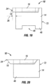
- Fig. 18 shows the second sipe element 20 with a male connector 26 on one end as previously discussed.
- a pair of legs 32, 54 are present, and the length 70 is less than the length of the second sipe element narrow section 22.
- the second terminal end 58 has both the second sipe element narrow section 22 and the second sipe element teardrop section 24 located thereon.
- the second leg 54 is also located at the second terminal end 58.
- a second sipe element 20 of this configuration may be used at the end of a series of sipe elements disposed within the mold segment base 28.
- the third sipe element 92 of Fig. 14 likewise does not have a male or female connector 26, 18 located at one of its terminal ends.
- Fig. 19 illustrates an alternative exemplary embodiment in which the first sipe element 12 has a female connector 18 located at the first terminal end 34 as discussed in previous embodiments.
- the first sipe element second terminal end 72 does not have a male or female connector 26, 18.
- the various elements such as the first sipe element teardrop section 16, the narrow section, and the leg end at the first sipe element second terminal end 72 and may end in a plane in some embodiments.
- the length of the first sipe element teardrop section 16 can be longer than the length of the narrow section.
- the sipe elements can be constructed so that only the female connector 18 is present and the male connector 26 is not present.
- Fig. 20 shows a further exemplary embodiment in which the first sipe element 12 has a first sipe element narrow section 14 but does not have a void at the first sipe element embedded end 46.
- the first sipe element 12 does have a pair of legs on an end opposite the first sipe element embedded end 46.
- the first sipe element teardrop section 16 is offset from the first sipe element narrow section 14 in the longitudinal direction and male and female connectors can be defined on opposite ends of the first sipe element 12.
- the first sipe element teardrop section 16 has angled, or tilted, ends and not ends that are parallel or substantially parallel to the ends of the first sipe element narrow section 14.
- the first terminal end 34 is the location at the first sipe element teardrop section 16 located at a position farthest from the first sipe element embedded end 46.
- the length of the angled first sipe element teardrop section 16 illustrated is measured between the closer of the two points of the opposite ends of the angled first sipe element teardrop section 16.
Landscapes
- Engineering & Computer Science (AREA)
- Mechanical Engineering (AREA)
- Moulds For Moulding Plastics Or The Like (AREA)
- Tires In General (AREA)
Claims (14)
- Formsegment (10; 74) zum Formen eines Reifens (42), umfassend:ein erstes Lamellenelement (12), das einen schmalen Abschnitt (14) des ersten Lamellenelementes aufweist, und einen tropfenförmigen Abschnitt (16) des ersten Lamellenelementes, wobei das erste Lamellenelement (12) einen Buchsenverbinder (18) aufweist;ein zweites Lamellenelement (20), das einen schmalen Abschnitt (22) des zweiten Lamellenelementes und einen tropfenförmigen Abschnitt (24) des zweiten Lamellenelementes aufweist, wobei das zweite Lamellenelement (20) einen Steckverbinder (26) aufweist; undeine Formsegmentbasis (28), die das erste Lamellenelement (12) und das zweite Lamellenelement (20) aufnimmt, wobei der Buchsenverbinder (18) des ersten Lamellenelementes (12) den Steckverbinder (26) des zweiten Lamellenelementes (20) aufnimmt,dadurch gekennzeichnet, dassder tropfenförmige Abschnitt (16) des ersten Lamellenelementes sich an einem ersten Anschlussende (34) des ersten Lamellenelementes (12) befindet, und wobei der schmale Abschnitt (14) des ersten Lamellenelementes gegenüber dem ersten Anschlussende (34) des ersten Lamellenelementes (12) versetzt ist und nicht am ersten Anschlussende (34) des ersten Lamellenelementes (12) angeordnet ist;das erste Verbindungsstück (32) am ersten Anschlussende (38) des zweiten Lamellenelementes (20) angeordnet ist, und wobei sich der schmale Abschnitt (22) des zweiten Lamellenelementes am ersten Anschlussende (38) des zweiten Lamellenelementes (20) befindet;der Steckverbinder (26) an einem ersten Anschlussende (38) des zweiten Lamellenelementes (20) angeordnet ist, wobei den tropfenförmigen Abschnitt (24) des zweiten Lamellenelementes gegenüber dem ersten Anschlussende (38) des zweiten Lamellenelementes (20) versetzt ist und nicht am ersten Anschlussende (38) des zweiten Lamellenelementes (20) angeordnet ist.
- Formsegment (10; 74) nach Anspruch 1, wobei die Formsegmentbasis (28) aus gießbarem Polysulfidformgummi hergestellt ist, und wobei das erste Lamellenelement (12) und das zweite Lamellenelement (20) in den gießbaren Polysulfidformgummi gedrückt werden, um darin aufgenommen zu werden, und wobei der schmale Abschnitt (14) des ersten Lamellenelementes und der schmale Abschnitt (22) des zweiten Lamellenelementes näher an der Formsegmentbasis (28) angeordnet sind, als der tropfenförmige Abschnitt (16) des ersten Lamellenelementes und der tropfenförmige Abschnitt (24) des zweiten Lamellenelementes.
- Formsegment (10; 74) nach den Ansprüchen 1 oder 2, wobei der Buchsenverbinder (18) ein Schlitz (30) ist, der in dem tropfenförmigen Abschnitt (16) des ersten Lamellenelementes definiert ist, und wobei der Steckverbinder (26) ein erstes Verbindungsstück (32) des zweiten Lamellenelementes (20) ist, wobei das erste Verbindungsstück (32) innerhalb des Schlitzes (30) angeordnet ist, wenn der Buchsenverbinder (18) des ersten Lamellenelementes (12) den Steckverbinder (26) des zweiten Lamellenelementes (20) aufnimmt.
- Formsegment (10; 74) nach den Ansprüchen 1 bis 3, wobei das zweite Lamellenelement (20) ein zweites Verbindungsstück (54) aufweist, der einen Abstand zum ersten Verbindungsstück (32) des zweiten Lamellenelementes (20) aufweist, wobei der tropfenförmige Abschnitt (24; 62) des zweiten Lamellenelementes sowohl in das erste als auch in das zweite Verbindungsstück (32; 54) des zweiten Lamellenelementes (20) angreift.
- Formsegment (10; 74) nach Anspruch 4, wobei das zweite Lamellenelement (20) ein zweites Anschlussende (58) aufweist und wobei der schmale Abschnitt (22) des zweiten Lamellenelementes und der tropfenförmige Abschnitt (24) des zweiten Lamellenelementes beide am zweiten Anschlussende (58) angeordnet sind.
- Formsegment (10; 74) nach Anspruch 4, wobei das zweite Lamellenelement (20) ein zweites Anschlussende (58) aufweist, und wobei der schmale Abschnitt (22) des zweiten Lamellenelementes am zweiten Anschlussende (58) angeordnet ist, und wobei der tropfenförmige Abschnitt (24) des zweiten Lamellenelementes von dem zweiten Anschlussende (58) mit Abstand und nicht an diesem angeordnet ist.
- Formsegment (10; 74) nach einem der Ansprüche 4 - 6, wobei das erste Verbindungsstück (32) des zweiten Lamellenelementes (20) mindestens 4 Millimeter lang ist, wobei das zweite Verbindungsstück (54) des zweiten Lamellenelementes (20) eine Länge von mindestens 4 Millimetern aufweist, und wobei der Abstand vom ersten Verbindungsstück (32) des zweiten Lamellenelementes (20) zum zweiten Verbindungsstück (54) des zweiten Lamellenelementes (20) mindestens 16 Millimeter beträgt, und wobei das zweite Lamellenelement (20) nur einen einzigen des tropfenförmigen Abschnitts (24) des zweiten Lamellenelementes aufweist.
- Formsegment (10; 74) nach Anspruch 3, wobei das erste Verbindungsstück (32) des zweiten Lamellenelementes (20) der einzige Schenkel des zweiten Lamellenelementes (20) am tropfenförmigen Abschnitt (24) des zweiten Lamellenelementes ist, und wobei der tropfenförmige Abschnitt (24) des zweiten Lamellenelementes eine Länge von 8 bis weniger als 24 Millimeter aufweist.
- Formsegment (10; 74) nach Anspruch 3, wobei ein zweites Verbindungsstück (54) und ein drittes Verbindungsstück (60) des zweiten Lamellenelementes (20) vorhanden sind, und wobei ein Paar der tropfenförmigen Abschnitt (62) des zweiten Lamellenelementes vorhanden ist, wobei das erste Verbindungsstück (32) des zweiten Lamellenelementes (20), das zweite Verbindungsstück (54) des zweiten Lamellenelementes (20) und das dritte Verbindungsstück (60) des zweiten Lamellenelementes (20) am Paar der tropfenförmigen Abschnitt (62) des zweiten Lamellenelementes angeordnet sind, und wobei das Paar der tropfenförmigen Abschnitt (62) des zweiten Lamellenelementes eine Länge von mehr als oder gleich 70 Millimetern hat.
- Formsegment (10; 74) nach Anspruch 1, wobei der Versatz des schmalen Abschnitts (14) des ersten Lamellenelementes gegenüber dem ersten Anschlussende (34) des ersten Lamellenelementes (12) 1 Millimeter beträgt, und wobei der Versatz des tropfenförmigen Abschnitts (24; 62) des zweiten Lamellenelementes gegenüber dem ersten Anschlussende (38) des zweiten Lamellenelementes (20) 1 Millimeter beträgt.
- Formsegment (10; 74) nach einem der Ansprüche 1-10, wobei der schmale Abschnitt (14) des ersten Lamellenelementes und der schmale Abschnitt (22) des zweiten Lamellenelementes ineinander greifen, wenn der Buchsenverbinder (18) des ersten Lamellenelementes (12) den Steckverbinder (26) des zweiten Lamellenelementes (20) aufnimmt.
- Formsegment (10; 74) nach einem der Ansprüche 1-11, wobei das erste Lamellenelement (12) und das zweite Lamellenelement (20) zur Bildung einer tropfenförmigen Längslamelle (44) in einem Reifen (42) verwendet werden.
- Formsegment (10; 74) nach einem der Ansprüche 1-12, wobei das erste Lamellenelement (12) ein eingebettetes Ende (46) des ersten Lamellenelementes aufweist, das einen Hohlraum (48) des ersten Lamellenelementes definiert, wobei das eingebettetes Ende (46) des ersten Lamellenelementes innerhalb der Formsegmentbasis (28) angeordnet ist, wenn die Formsegmentbasis (28) das erste Lamellenelement (12) aufnimmt;
wobei das zweite Lamellenelement (20) ein eingebettetes Ende (50) des zweiten Lamellenelementes aufweist, das einen Hohlraum (52) des zweiten Lamellenelementes definiert, wobei das eingebettete Ende (50) des zweiten Lamellenelementes innerhalb der Formsegmentbasis (28) angeordnet ist, wenn die Formsegmentbasis (28) das zweite Lamellenelement (20) aufnimmt. - Formsegment (10; 74) nach einem der Ansprüche 1-13, wobei das erste Lamellenelement (12) ein erstes Anschlussende des ersten Lamellenelementes aufweist und der Buchsenverbinder (18) am ersten Anschlussende des ersten Lamellenelementes angeordnet ist, wobei das erste Lamellenelement (12) ein zweites Anschlussende (72) des ersten Lamellenelementes aufweist und der schmale Abschnitt (14) des ersten Lamellenelementes und der tropfenförmige Abschnitt (16) des ersten Lamellenelementes beide am zweiten Anschlussende (72) des ersten Lamellenelementes angeordnet sind.
Applications Claiming Priority (2)
| Application Number | Priority Date | Filing Date | Title |
|---|---|---|---|
| US201862781978P | 2018-12-19 | 2018-12-19 | |
| PCT/IB2019/060867 WO2020128798A1 (en) | 2018-12-19 | 2019-12-16 | Mold segment for tire having connected first and second sipe elements |
Publications (2)
| Publication Number | Publication Date |
|---|---|
| EP3898211A1 EP3898211A1 (de) | 2021-10-27 |
| EP3898211B1 true EP3898211B1 (de) | 2024-10-23 |
Family
ID=69137956
Family Applications (1)
| Application Number | Title | Priority Date | Filing Date |
|---|---|---|---|
| EP19832458.4A Active EP3898211B1 (de) | 2018-12-19 | 2019-12-16 | Formsegment für reifen mit verbundenen ersten und zweiten lamellenelementen |
Country Status (4)
| Country | Link |
|---|---|
| US (1) | US12226969B2 (de) |
| EP (1) | EP3898211B1 (de) |
| CN (1) | CN113195204B (de) |
| WO (1) | WO2020128798A1 (de) |
Families Citing this family (2)
| Publication number | Priority date | Publication date | Assignee | Title |
|---|---|---|---|---|
| WO2022144572A1 (en) * | 2020-12-29 | 2022-07-07 | Compagnie Generale Des Etablissements Michelin | Flexible mold segment with sipe element having a projection for use in forming a tire |
| JP7578498B2 (ja) * | 2021-02-09 | 2024-11-06 | 株式会社ブリヂストン | サイプブレード及びタイヤ成型用金型並びにタイヤ製造方法 |
Family Cites Families (14)
| Publication number | Priority date | Publication date | Assignee | Title |
|---|---|---|---|---|
| US6196818B1 (en) * | 1999-03-15 | 2001-03-06 | Bridgestone/Firestone Research, Inc. | Mold section and die ribs for tire curing mold |
| JP3712109B2 (ja) | 2000-09-14 | 2005-11-02 | 日本碍子株式会社 | 3次元曲げ金型の製造方法、サイプブレード若しくは消失模型の製造方法及びタイヤ金型の製造方法 |
| US6863106B2 (en) * | 2001-09-21 | 2005-03-08 | The Goodyear Tire & Rubber Company | Expandable tire building drum with alternating fixed and expandable segments, and contours for sidewall inserts |
| KR100551880B1 (ko) * | 2004-07-01 | 2006-02-13 | 한국타이어 주식회사 | 커프 성형용 블레이드 |
| FR2946915B1 (fr) * | 2009-06-19 | 2011-06-17 | Michelin Soc Tech | Dispositif amovible de moulage d'une paroi flexible dans un sillon de sculpture de pneumatique |
| FR2960473A1 (fr) * | 2010-05-31 | 2011-12-02 | Michelin Soc Tech | Element d'une garniture de moule pour mouler et vulcaniser une partie d'une bande de roulement d'un pneumatique. |
| FR3009229B1 (fr) * | 2013-08-05 | 2015-07-17 | Michelin & Cie | Moule pour pneumatique comportant un insert annulaire demontable |
| FR3014734B1 (fr) | 2013-12-12 | 2016-08-12 | Michelin & Cie | Element moulant comportant un moyen d'assemblage particulier |
| JP6253516B2 (ja) * | 2014-05-27 | 2017-12-27 | 株式会社ブリヂストン | タイヤモールド |
| JP2017531584A (ja) * | 2014-09-30 | 2017-10-26 | コンパニー ゼネラール デ エタブリッスマン ミシュラン | サイプ成形部材用補剛材 |
| WO2016200392A1 (en) | 2015-06-11 | 2016-12-15 | Compagnie Generale Des Etablissements Michelin | Set of molding elements and mold |
| EP3356103B1 (de) * | 2015-09-30 | 2021-12-29 | Compagnie Générale des Etablissements Michelin | Formelement zur herstellung einer geräuschmindernden lauffläche |
| FR3063242A1 (fr) | 2017-02-28 | 2018-08-31 | Compagnie Generale Des Etablissements Michelin | Ensemble d'elements moulants pour moule de pneumatique |
| FR3081364B1 (fr) | 2018-05-25 | 2020-06-12 | Compagnie Generale Des Etablissements Michelin | Ensemble d'elements moulants |
-
2019
- 2019-12-16 US US17/311,569 patent/US12226969B2/en active Active
- 2019-12-16 CN CN201980083844.8A patent/CN113195204B/zh active Active
- 2019-12-16 EP EP19832458.4A patent/EP3898211B1/de active Active
- 2019-12-16 WO PCT/IB2019/060867 patent/WO2020128798A1/en not_active Ceased
Also Published As
| Publication number | Publication date |
|---|---|
| EP3898211A1 (de) | 2021-10-27 |
| CN113195204B (zh) | 2023-02-17 |
| WO2020128798A1 (en) | 2020-06-25 |
| CN113195204A (zh) | 2021-07-30 |
| US20220024165A1 (en) | 2022-01-27 |
| US12226969B2 (en) | 2025-02-18 |
Similar Documents
| Publication | Publication Date | Title |
|---|---|---|
| US8215939B2 (en) | Tire vulcanization forming mold | |
| EP3307530B1 (de) | Satz von formelementen und form | |
| EP3898211B1 (de) | Formsegment für reifen mit verbundenen ersten und zweiten lamellenelementen | |
| US6955782B1 (en) | Method of molding a tire and mold therefor | |
| CN102083603A (zh) | 具有标引构件的模具段和对准模具段的方法 | |
| EP2349700B1 (de) | Verfahren und vorrichtung zum formen und vulkanisieren von fahrzeugreifen | |
| EP1652659B1 (de) | Kern zur Reifenherstellung | |
| EP1036645A2 (de) | Vulkanisierformwerkzeug für Reifen | |
| CN111741844A (zh) | 用于轮胎的硫化胶囊 | |
| CN113195189B (zh) | 硫化成形用模具及利用该模具制造的充气轮胎 | |
| CN116723922B (zh) | 用于形成轮胎的具有带突起的刀槽花纹元件的柔性模具段 | |
| JP2025527863A (ja) | 改良されたタイヤ性能及び経済的な型製造のための波形タイヤサイプ | |
| JP2025527864A (ja) | 改良されたタイヤ性能及び経済的な型製造のための波形サイプ成形部材 | |
| US7717691B2 (en) | Tire mold with vent inlet disposed under mold rib | |
| US8425213B2 (en) | Apparatus for vulcanization and moulding of tyres and method for manufacturing the same | |
| US3474499A (en) | Tire mold clamping ring | |
| EP4072841B1 (de) | Formsegment mit verbundenen ersten und zweiten lamellenelementen zur verwendung bei der reifenherstellung | |
| EP1238772A3 (de) | Vulkanisierformwerkzeug für Luftreifen | |
| CN113195188A (zh) | 硫化成形用模具及利用该模具制造的充气轮胎 | |
| CN113195190A (zh) | 硫化成形用模具及利用该模具制造的充气轮胎 | |
| EP3670164B1 (de) | Gewellter reifenbalg | |
| WO2001038109A1 (en) | A method of molding a tire and mold therefor |
Legal Events
| Date | Code | Title | Description |
|---|---|---|---|
| STAA | Information on the status of an ep patent application or granted ep patent |
Free format text: STATUS: UNKNOWN |
|
| STAA | Information on the status of an ep patent application or granted ep patent |
Free format text: STATUS: THE INTERNATIONAL PUBLICATION HAS BEEN MADE |
|
| PUAI | Public reference made under article 153(3) epc to a published international application that has entered the european phase |
Free format text: ORIGINAL CODE: 0009012 |
|
| STAA | Information on the status of an ep patent application or granted ep patent |
Free format text: STATUS: REQUEST FOR EXAMINATION WAS MADE |
|
| 17P | Request for examination filed |
Effective date: 20210602 |
|
| AK | Designated contracting states |
Kind code of ref document: A1 Designated state(s): AL AT BE BG CH CY CZ DE DK EE ES FI FR GB GR HR HU IE IS IT LI LT LU LV MC MK MT NL NO PL PT RO RS SE SI SK SM TR |
|
| DAV | Request for validation of the european patent (deleted) | ||
| DAX | Request for extension of the european patent (deleted) | ||
| STAA | Information on the status of an ep patent application or granted ep patent |
Free format text: STATUS: EXAMINATION IS IN PROGRESS |
|
| 17Q | First examination report despatched |
Effective date: 20230418 |
|
| GRAP | Despatch of communication of intention to grant a patent |
Free format text: ORIGINAL CODE: EPIDOSNIGR1 |
|
| STAA | Information on the status of an ep patent application or granted ep patent |
Free format text: STATUS: GRANT OF PATENT IS INTENDED |
|
| INTG | Intention to grant announced |
Effective date: 20240524 |
|
| GRAS | Grant fee paid |
Free format text: ORIGINAL CODE: EPIDOSNIGR3 |
|
| GRAA | (expected) grant |
Free format text: ORIGINAL CODE: 0009210 |
|
| STAA | Information on the status of an ep patent application or granted ep patent |
Free format text: STATUS: THE PATENT HAS BEEN GRANTED |
|
| AK | Designated contracting states |
Kind code of ref document: B1 Designated state(s): AL AT BE BG CH CY CZ DE DK EE ES FI FR GB GR HR HU IE IS IT LI LT LU LV MC MK MT NL NO PL PT RO RS SE SI SK SM TR |
|
| REG | Reference to a national code |
Ref country code: GB Ref legal event code: FG4D |
|
| REG | Reference to a national code |
Ref country code: CH Ref legal event code: EP |
|
| REG | Reference to a national code |
Ref country code: DE Ref legal event code: R096 Ref document number: 602019060881 Country of ref document: DE |
|
| REG | Reference to a national code |
Ref country code: IE Ref legal event code: FG4D |
|
| REG | Reference to a national code |
Ref country code: LT Ref legal event code: MG9D |
|
| REG | Reference to a national code |
Ref country code: NL Ref legal event code: MP Effective date: 20241023 |
|
| REG | Reference to a national code |
Ref country code: AT Ref legal event code: MK05 Ref document number: 1734518 Country of ref document: AT Kind code of ref document: T Effective date: 20241023 |
|
| PG25 | Lapsed in a contracting state [announced via postgrant information from national office to epo] |
Ref country code: NL Free format text: LAPSE BECAUSE OF FAILURE TO SUBMIT A TRANSLATION OF THE DESCRIPTION OR TO PAY THE FEE WITHIN THE PRESCRIBED TIME-LIMIT Effective date: 20241023 |
|
| PG25 | Lapsed in a contracting state [announced via postgrant information from national office to epo] |
Ref country code: NL Free format text: LAPSE BECAUSE OF FAILURE TO SUBMIT A TRANSLATION OF THE DESCRIPTION OR TO PAY THE FEE WITHIN THE PRESCRIBED TIME-LIMIT Effective date: 20241023 |
|
| PG25 | Lapsed in a contracting state [announced via postgrant information from national office to epo] |
Ref country code: PT Free format text: LAPSE BECAUSE OF FAILURE TO SUBMIT A TRANSLATION OF THE DESCRIPTION OR TO PAY THE FEE WITHIN THE PRESCRIBED TIME-LIMIT Effective date: 20250224 Ref country code: IS Free format text: LAPSE BECAUSE OF FAILURE TO SUBMIT A TRANSLATION OF THE DESCRIPTION OR TO PAY THE FEE WITHIN THE PRESCRIBED TIME-LIMIT Effective date: 20250223 Ref country code: HR Free format text: LAPSE BECAUSE OF FAILURE TO SUBMIT A TRANSLATION OF THE DESCRIPTION OR TO PAY THE FEE WITHIN THE PRESCRIBED TIME-LIMIT Effective date: 20241023 |
|
| PG25 | Lapsed in a contracting state [announced via postgrant information from national office to epo] |
Ref country code: FI Free format text: LAPSE BECAUSE OF FAILURE TO SUBMIT A TRANSLATION OF THE DESCRIPTION OR TO PAY THE FEE WITHIN THE PRESCRIBED TIME-LIMIT Effective date: 20241023 |
|
| PG25 | Lapsed in a contracting state [announced via postgrant information from national office to epo] |
Ref country code: BG Free format text: LAPSE BECAUSE OF FAILURE TO SUBMIT A TRANSLATION OF THE DESCRIPTION OR TO PAY THE FEE WITHIN THE PRESCRIBED TIME-LIMIT Effective date: 20241023 |
|
| PG25 | Lapsed in a contracting state [announced via postgrant information from national office to epo] |
Ref country code: ES Free format text: LAPSE BECAUSE OF FAILURE TO SUBMIT A TRANSLATION OF THE DESCRIPTION OR TO PAY THE FEE WITHIN THE PRESCRIBED TIME-LIMIT Effective date: 20241023 |
|
| PG25 | Lapsed in a contracting state [announced via postgrant information from national office to epo] |
Ref country code: NO Free format text: LAPSE BECAUSE OF FAILURE TO SUBMIT A TRANSLATION OF THE DESCRIPTION OR TO PAY THE FEE WITHIN THE PRESCRIBED TIME-LIMIT Effective date: 20250123 |
|
| PG25 | Lapsed in a contracting state [announced via postgrant information from national office to epo] |
Ref country code: LV Free format text: LAPSE BECAUSE OF FAILURE TO SUBMIT A TRANSLATION OF THE DESCRIPTION OR TO PAY THE FEE WITHIN THE PRESCRIBED TIME-LIMIT Effective date: 20241023 Ref country code: GR Free format text: LAPSE BECAUSE OF FAILURE TO SUBMIT A TRANSLATION OF THE DESCRIPTION OR TO PAY THE FEE WITHIN THE PRESCRIBED TIME-LIMIT Effective date: 20250124 Ref country code: AT Free format text: LAPSE BECAUSE OF FAILURE TO SUBMIT A TRANSLATION OF THE DESCRIPTION OR TO PAY THE FEE WITHIN THE PRESCRIBED TIME-LIMIT Effective date: 20241023 |
|
| PG25 | Lapsed in a contracting state [announced via postgrant information from national office to epo] |
Ref country code: PL Free format text: LAPSE BECAUSE OF FAILURE TO SUBMIT A TRANSLATION OF THE DESCRIPTION OR TO PAY THE FEE WITHIN THE PRESCRIBED TIME-LIMIT Effective date: 20241023 |
|
| PG25 | Lapsed in a contracting state [announced via postgrant information from national office to epo] |
Ref country code: RS Free format text: LAPSE BECAUSE OF FAILURE TO SUBMIT A TRANSLATION OF THE DESCRIPTION OR TO PAY THE FEE WITHIN THE PRESCRIBED TIME-LIMIT Effective date: 20250123 |
|
| PG25 | Lapsed in a contracting state [announced via postgrant information from national office to epo] |
Ref country code: SM Free format text: LAPSE BECAUSE OF FAILURE TO SUBMIT A TRANSLATION OF THE DESCRIPTION OR TO PAY THE FEE WITHIN THE PRESCRIBED TIME-LIMIT Effective date: 20241023 |
|
| PG25 | Lapsed in a contracting state [announced via postgrant information from national office to epo] |
Ref country code: MC Free format text: LAPSE BECAUSE OF FAILURE TO SUBMIT A TRANSLATION OF THE DESCRIPTION OR TO PAY THE FEE WITHIN THE PRESCRIBED TIME-LIMIT Effective date: 20241023 |
|
| PG25 | Lapsed in a contracting state [announced via postgrant information from national office to epo] |
Ref country code: DK Free format text: LAPSE BECAUSE OF FAILURE TO SUBMIT A TRANSLATION OF THE DESCRIPTION OR TO PAY THE FEE WITHIN THE PRESCRIBED TIME-LIMIT Effective date: 20241023 |
|
| PG25 | Lapsed in a contracting state [announced via postgrant information from national office to epo] |
Ref country code: EE Free format text: LAPSE BECAUSE OF FAILURE TO SUBMIT A TRANSLATION OF THE DESCRIPTION OR TO PAY THE FEE WITHIN THE PRESCRIBED TIME-LIMIT Effective date: 20241023 |
|
| PG25 | Lapsed in a contracting state [announced via postgrant information from national office to epo] |
Ref country code: RO Free format text: LAPSE BECAUSE OF FAILURE TO SUBMIT A TRANSLATION OF THE DESCRIPTION OR TO PAY THE FEE WITHIN THE PRESCRIBED TIME-LIMIT Effective date: 20241023 |
|
| REG | Reference to a national code |
Ref country code: DE Ref legal event code: R097 Ref document number: 602019060881 Country of ref document: DE |
|
| PG25 | Lapsed in a contracting state [announced via postgrant information from national office to epo] |
Ref country code: SK Free format text: LAPSE BECAUSE OF FAILURE TO SUBMIT A TRANSLATION OF THE DESCRIPTION OR TO PAY THE FEE WITHIN THE PRESCRIBED TIME-LIMIT Effective date: 20241023 |
|
| PG25 | Lapsed in a contracting state [announced via postgrant information from national office to epo] |
Ref country code: CZ Free format text: LAPSE BECAUSE OF FAILURE TO SUBMIT A TRANSLATION OF THE DESCRIPTION OR TO PAY THE FEE WITHIN THE PRESCRIBED TIME-LIMIT Effective date: 20241023 |
|
| PG25 | Lapsed in a contracting state [announced via postgrant information from national office to epo] |
Ref country code: IT Free format text: LAPSE BECAUSE OF FAILURE TO SUBMIT A TRANSLATION OF THE DESCRIPTION OR TO PAY THE FEE WITHIN THE PRESCRIBED TIME-LIMIT Effective date: 20241023 |
|
| REG | Reference to a national code |
Ref country code: CH Ref legal event code: PL |
|
| PG25 | Lapsed in a contracting state [announced via postgrant information from national office to epo] |
Ref country code: LU Free format text: LAPSE BECAUSE OF NON-PAYMENT OF DUE FEES Effective date: 20241216 |
|
| PLBE | No opposition filed within time limit |
Free format text: ORIGINAL CODE: 0009261 |
|
| STAA | Information on the status of an ep patent application or granted ep patent |
Free format text: STATUS: NO OPPOSITION FILED WITHIN TIME LIMIT |
|
| PG25 | Lapsed in a contracting state [announced via postgrant information from national office to epo] |
Ref country code: SE Free format text: LAPSE BECAUSE OF FAILURE TO SUBMIT A TRANSLATION OF THE DESCRIPTION OR TO PAY THE FEE WITHIN THE PRESCRIBED TIME-LIMIT Effective date: 20241023 |
|
| GBPC | Gb: european patent ceased through non-payment of renewal fee |
Effective date: 20250123 |
|
| 26N | No opposition filed |
Effective date: 20250724 |
|
| REG | Reference to a national code |
Ref country code: BE Ref legal event code: MM Effective date: 20241231 |
|
| PG25 | Lapsed in a contracting state [announced via postgrant information from national office to epo] |
Ref country code: BE Free format text: LAPSE BECAUSE OF NON-PAYMENT OF DUE FEES Effective date: 20241231 Ref country code: GB Free format text: LAPSE BECAUSE OF NON-PAYMENT OF DUE FEES Effective date: 20250123 |
|
| PG25 | Lapsed in a contracting state [announced via postgrant information from national office to epo] |
Ref country code: CH Free format text: LAPSE BECAUSE OF NON-PAYMENT OF DUE FEES Effective date: 20241231 |
|
| PG25 | Lapsed in a contracting state [announced via postgrant information from national office to epo] |
Ref country code: IE Free format text: LAPSE BECAUSE OF NON-PAYMENT OF DUE FEES Effective date: 20241216 |
|
| PGFP | Annual fee paid to national office [announced via postgrant information from national office to epo] |
Ref country code: DE Payment date: 20251211 Year of fee payment: 7 |
|
| PGFP | Annual fee paid to national office [announced via postgrant information from national office to epo] |
Ref country code: FR Payment date: 20251229 Year of fee payment: 7 |