EP3898340B1 - Élément d'isolation contre le bruit pour la paroi frontale d'une carrosserie de véhicule et élément support pour un tel élément d'isolation contre le bruit - Google Patents
Élément d'isolation contre le bruit pour la paroi frontale d'une carrosserie de véhicule et élément support pour un tel élément d'isolation contre le bruit Download PDFInfo
- Publication number
- EP3898340B1 EP3898340B1 EP19832848.6A EP19832848A EP3898340B1 EP 3898340 B1 EP3898340 B1 EP 3898340B1 EP 19832848 A EP19832848 A EP 19832848A EP 3898340 B1 EP3898340 B1 EP 3898340B1
- Authority
- EP
- European Patent Office
- Prior art keywords
- sound
- carrier layer
- hole
- plastic carrier
- layer
- Prior art date
- Legal status (The legal status is an assumption and is not a legal conclusion. Google has not performed a legal analysis and makes no representation as to the accuracy of the status listed.)
- Active
Links
Images


Classifications
-
- B—PERFORMING OPERATIONS; TRANSPORTING
- B60—VEHICLES IN GENERAL
- B60R—VEHICLES, VEHICLE FITTINGS, OR VEHICLE PARTS, NOT OTHERWISE PROVIDED FOR
- B60R13/00—Elements for body-finishing, identifying, or decorating; Arrangements or adaptations for advertising purposes
- B60R13/08—Insulating elements, e.g. for sound insulation
- B60R13/0815—Acoustic or thermal insulation of passenger compartments
- B60R13/083—Acoustic or thermal insulation of passenger compartments for fire walls or floors
-
- B—PERFORMING OPERATIONS; TRANSPORTING
- B60—VEHICLES IN GENERAL
- B60R—VEHICLES, VEHICLE FITTINGS, OR VEHICLE PARTS, NOT OTHERWISE PROVIDED FOR
- B60R13/00—Elements for body-finishing, identifying, or decorating; Arrangements or adaptations for advertising purposes
- B60R13/08—Insulating elements, e.g. for sound insulation
-
- B—PERFORMING OPERATIONS; TRANSPORTING
- B32—LAYERED PRODUCTS
- B32B—LAYERED PRODUCTS, i.e. PRODUCTS BUILT-UP OF STRATA OF FLAT OR NON-FLAT, e.g. CELLULAR OR HONEYCOMB, FORM
- B32B25/00—Layered products comprising a layer of natural or synthetic rubber
- B32B25/04—Layered products comprising a layer of natural or synthetic rubber comprising rubber as the main or only constituent of a layer, which is next to another layer of the same or of a different material
- B32B25/045—Layered products comprising a layer of natural or synthetic rubber comprising rubber as the main or only constituent of a layer, which is next to another layer of the same or of a different material of foam
-
- B—PERFORMING OPERATIONS; TRANSPORTING
- B32—LAYERED PRODUCTS
- B32B—LAYERED PRODUCTS, i.e. PRODUCTS BUILT-UP OF STRATA OF FLAT OR NON-FLAT, e.g. CELLULAR OR HONEYCOMB, FORM
- B32B25/00—Layered products comprising a layer of natural or synthetic rubber
- B32B25/14—Layered products comprising a layer of natural or synthetic rubber comprising synthetic rubber copolymers
-
- B—PERFORMING OPERATIONS; TRANSPORTING
- B32—LAYERED PRODUCTS
- B32B—LAYERED PRODUCTS, i.e. PRODUCTS BUILT-UP OF STRATA OF FLAT OR NON-FLAT, e.g. CELLULAR OR HONEYCOMB, FORM
- B32B27/00—Layered products comprising a layer of synthetic resin
- B32B27/06—Layered products comprising a layer of synthetic resin as the main or only constituent of a layer, which is next to another layer of the same or of a different material
- B32B27/065—Layered products comprising a layer of synthetic resin as the main or only constituent of a layer, which is next to another layer of the same or of a different material of foam
-
- B—PERFORMING OPERATIONS; TRANSPORTING
- B32—LAYERED PRODUCTS
- B32B—LAYERED PRODUCTS, i.e. PRODUCTS BUILT-UP OF STRATA OF FLAT OR NON-FLAT, e.g. CELLULAR OR HONEYCOMB, FORM
- B32B27/00—Layered products comprising a layer of synthetic resin
- B32B27/30—Layered products comprising a layer of synthetic resin comprising vinyl (co)polymers; comprising acrylic (co)polymers
-
- B—PERFORMING OPERATIONS; TRANSPORTING
- B32—LAYERED PRODUCTS
- B32B—LAYERED PRODUCTS, i.e. PRODUCTS BUILT-UP OF STRATA OF FLAT OR NON-FLAT, e.g. CELLULAR OR HONEYCOMB, FORM
- B32B27/00—Layered products comprising a layer of synthetic resin
- B32B27/32—Layered products comprising a layer of synthetic resin comprising polyolefins
-
- B—PERFORMING OPERATIONS; TRANSPORTING
- B32—LAYERED PRODUCTS
- B32B—LAYERED PRODUCTS, i.e. PRODUCTS BUILT-UP OF STRATA OF FLAT OR NON-FLAT, e.g. CELLULAR OR HONEYCOMB, FORM
- B32B3/00—Layered products comprising a layer with external or internal discontinuities or unevennesses, or a layer of non-planar shape; Layered products comprising a layer having particular features of form
- B32B3/26—Layered products comprising a layer with external or internal discontinuities or unevennesses, or a layer of non-planar shape; Layered products comprising a layer having particular features of form characterised by a particular shape of the outline of the cross-section of a continuous layer; characterised by a layer with cavities or internal voids ; characterised by an apertured layer
- B32B3/266—Layered products comprising a layer with external or internal discontinuities or unevennesses, or a layer of non-planar shape; Layered products comprising a layer having particular features of form characterised by a particular shape of the outline of the cross-section of a continuous layer; characterised by a layer with cavities or internal voids ; characterised by an apertured layer characterised by an apertured layer, the apertures going through the whole thickness of the layer, e.g. expanded metal, perforated layer, slit layer regular cells B32B3/12
-
- B—PERFORMING OPERATIONS; TRANSPORTING
- B32—LAYERED PRODUCTS
- B32B—LAYERED PRODUCTS, i.e. PRODUCTS BUILT-UP OF STRATA OF FLAT OR NON-FLAT, e.g. CELLULAR OR HONEYCOMB, FORM
- B32B3/00—Layered products comprising a layer with external or internal discontinuities or unevennesses, or a layer of non-planar shape; Layered products comprising a layer having particular features of form
- B32B3/26—Layered products comprising a layer with external or internal discontinuities or unevennesses, or a layer of non-planar shape; Layered products comprising a layer having particular features of form characterised by a particular shape of the outline of the cross-section of a continuous layer; characterised by a layer with cavities or internal voids ; characterised by an apertured layer
- B32B3/30—Layered products comprising a layer with external or internal discontinuities or unevennesses, or a layer of non-planar shape; Layered products comprising a layer having particular features of form characterised by a particular shape of the outline of the cross-section of a continuous layer; characterised by a layer with cavities or internal voids ; characterised by an apertured layer characterised by a layer formed with recesses or projections, e.g. hollows, grooves, protuberances, ribs
-
- B—PERFORMING OPERATIONS; TRANSPORTING
- B32—LAYERED PRODUCTS
- B32B—LAYERED PRODUCTS, i.e. PRODUCTS BUILT-UP OF STRATA OF FLAT OR NON-FLAT, e.g. CELLULAR OR HONEYCOMB, FORM
- B32B5/00—Layered products characterised by the non- homogeneity or physical structure, i.e. comprising a fibrous, filamentary, particulate or foam layer; Layered products characterised by having a layer differing constitutionally or physically in different parts
- B32B5/18—Layered products characterised by the non- homogeneity or physical structure, i.e. comprising a fibrous, filamentary, particulate or foam layer; Layered products characterised by having a layer differing constitutionally or physically in different parts characterised by features of a layer of foamed material
-
- B—PERFORMING OPERATIONS; TRANSPORTING
- B32—LAYERED PRODUCTS
- B32B—LAYERED PRODUCTS, i.e. PRODUCTS BUILT-UP OF STRATA OF FLAT OR NON-FLAT, e.g. CELLULAR OR HONEYCOMB, FORM
- B32B5/00—Layered products characterised by the non- homogeneity or physical structure, i.e. comprising a fibrous, filamentary, particulate or foam layer; Layered products characterised by having a layer differing constitutionally or physically in different parts
- B32B5/22—Layered products characterised by the non- homogeneity or physical structure, i.e. comprising a fibrous, filamentary, particulate or foam layer; Layered products characterised by having a layer differing constitutionally or physically in different parts characterised by the presence of two or more layers which are next to each other and are fibrous, filamentary, formed of particles or foamed
- B32B5/32—Layered products characterised by the non- homogeneity or physical structure, i.e. comprising a fibrous, filamentary, particulate or foam layer; Layered products characterised by having a layer differing constitutionally or physically in different parts characterised by the presence of two or more layers which are next to each other and are fibrous, filamentary, formed of particles or foamed at least two layers being foamed and next to each other
-
- B—PERFORMING OPERATIONS; TRANSPORTING
- B32—LAYERED PRODUCTS
- B32B—LAYERED PRODUCTS, i.e. PRODUCTS BUILT-UP OF STRATA OF FLAT OR NON-FLAT, e.g. CELLULAR OR HONEYCOMB, FORM
- B32B7/00—Layered products characterised by the relation between layers; Layered products characterised by the relative orientation of features between layers, or by the relative values of a measurable parameter between layers, i.e. products comprising layers having different physical, chemical or physicochemical properties; Layered products characterised by the interconnection of layers
- B32B7/04—Interconnection of layers
- B32B7/08—Interconnection of layers by mechanical means
-
- B—PERFORMING OPERATIONS; TRANSPORTING
- B60—VEHICLES IN GENERAL
- B60R—VEHICLES, VEHICLE FITTINGS, OR VEHICLE PARTS, NOT OTHERWISE PROVIDED FOR
- B60R13/00—Elements for body-finishing, identifying, or decorating; Arrangements or adaptations for advertising purposes
- B60R13/08—Insulating elements, e.g. for sound insulation
- B60R13/0815—Acoustic or thermal insulation of passenger compartments
-
- B—PERFORMING OPERATIONS; TRANSPORTING
- B60—VEHICLES IN GENERAL
- B60R—VEHICLES, VEHICLE FITTINGS, OR VEHICLE PARTS, NOT OTHERWISE PROVIDED FOR
- B60R13/00—Elements for body-finishing, identifying, or decorating; Arrangements or adaptations for advertising purposes
- B60R13/08—Insulating elements, e.g. for sound insulation
- B60R13/0846—Insulating elements, e.g. for sound insulation for duct, cable or rod passages, e.g. between engine and passenger compartments
-
- G—PHYSICS
- G10—MUSICAL INSTRUMENTS; ACOUSTICS
- G10K—SOUND-PRODUCING DEVICES; METHODS OR DEVICES FOR PROTECTING AGAINST, OR FOR DAMPING, NOISE OR OTHER ACOUSTIC WAVES IN GENERAL; ACOUSTICS NOT OTHERWISE PROVIDED FOR
- G10K11/00—Methods or devices for transmitting, conducting or directing sound in general; Methods or devices for protecting against, or for damping, noise or other acoustic waves in general
- G10K11/16—Methods or devices for protecting against, or for damping, noise or other acoustic waves in general
- G10K11/162—Selection of materials
- G10K11/168—Plural layers of different materials, e.g. sandwiches
-
- B—PERFORMING OPERATIONS; TRANSPORTING
- B32—LAYERED PRODUCTS
- B32B—LAYERED PRODUCTS, i.e. PRODUCTS BUILT-UP OF STRATA OF FLAT OR NON-FLAT, e.g. CELLULAR OR HONEYCOMB, FORM
- B32B2250/00—Layers arrangement
- B32B2250/02—2 layers
-
- B—PERFORMING OPERATIONS; TRANSPORTING
- B32—LAYERED PRODUCTS
- B32B—LAYERED PRODUCTS, i.e. PRODUCTS BUILT-UP OF STRATA OF FLAT OR NON-FLAT, e.g. CELLULAR OR HONEYCOMB, FORM
- B32B2250/00—Layers arrangement
- B32B2250/24—All layers being polymeric
-
- B—PERFORMING OPERATIONS; TRANSPORTING
- B32—LAYERED PRODUCTS
- B32B—LAYERED PRODUCTS, i.e. PRODUCTS BUILT-UP OF STRATA OF FLAT OR NON-FLAT, e.g. CELLULAR OR HONEYCOMB, FORM
- B32B2266/00—Composition of foam
- B32B2266/02—Organic
- B32B2266/0214—Materials belonging to B32B27/00
- B32B2266/0278—Polyurethane
-
- B—PERFORMING OPERATIONS; TRANSPORTING
- B32—LAYERED PRODUCTS
- B32B—LAYERED PRODUCTS, i.e. PRODUCTS BUILT-UP OF STRATA OF FLAT OR NON-FLAT, e.g. CELLULAR OR HONEYCOMB, FORM
- B32B2305/00—Condition, form or state of the layers or laminate
- B32B2305/02—Cellular or porous
- B32B2305/022—Foam
-
- B—PERFORMING OPERATIONS; TRANSPORTING
- B32—LAYERED PRODUCTS
- B32B—LAYERED PRODUCTS, i.e. PRODUCTS BUILT-UP OF STRATA OF FLAT OR NON-FLAT, e.g. CELLULAR OR HONEYCOMB, FORM
- B32B2307/00—Properties of the layers or laminate
- B32B2307/10—Properties of the layers or laminate having particular acoustical properties
- B32B2307/102—Insulating
-
- B—PERFORMING OPERATIONS; TRANSPORTING
- B32—LAYERED PRODUCTS
- B32B—LAYERED PRODUCTS, i.e. PRODUCTS BUILT-UP OF STRATA OF FLAT OR NON-FLAT, e.g. CELLULAR OR HONEYCOMB, FORM
- B32B2605/00—Vehicles
- B32B2605/08—Cars
Definitions
- the invention relates to a sound insulation element for the front wall of a vehicle body that separates the passenger compartment from the engine compartment.
- the invention also relates to a support element for a sound insulation element for arrangement on the front wall of a vehicle body.
- the US 2007/218790 discloses a sound insulation element for the front wall of a vehicle body arranged between the passenger compartment and the engine compartment, with a composite component which has a plastic carrier layer and a sound damping layer connected to it, wherein the composite component has a front side which, when viewed in its installed state, faces the passenger compartment and is formed by the outer surface of the plastic carrier layer and at least one first through-opening in the composite component, wherein the first through-opening has a carrier layer hole formed in the plastic carrier layer with a hole edge.
- Such sound insulation elements have a sandwich structure that has a plastic carrier layer, also known as a heavy layer, and a sound-absorbing layer made of sound-absorbing material, in particular a PUR foam material, that is molded onto the plastic carrier layer.
- the bulkhead of the vehicle body has several passages for cables, pipes or components. Accordingly, the sound insulation element is also provided with through-openings that are typically aligned with the passages in the bulkhead.
- through-openings that are typically aligned with the passages in the bulkhead.
- One possible measure for implementing such protection is to foam the edge of a through hole in the sound insulation element or to surround it with sound-absorbing material.
- the soundproofing material is typically molded onto the plastic carrier layer in a specially designed mold (usually a foaming tool) into which the plastic carrier layer is inserted.
- the plastic carrier layer has previously been manufactured in another mold designed for this purpose.
- the soundproofing material In the area of hole edges in the plastic carrier layer that are at least partially embedded in soundproofing material, the soundproofing material must be able to reach at least partially into the carrier layer hole.
- the soundproofing material should partially enclose the hole edge on both sides of the plastic carrier layer. In both cases, this can lead to the plastic carrier layer "floating" within the mold in which it is inserted during the manufacturing process, which can lead to unsatisfactory manufacturing results.
- the corresponding molds for molding the sound-absorbing material onto the plastic carrier layer have hold-down pins that hold the plastic carrier layer down along a hole edge that is to be at least partially surrounded by sound-absorbing material.
- Such mold hold-down pins increase the manufacturing costs of the mold and make the cleaning process that generally has to be carried out from time to time with such molds more difficult.
- the sound-absorbing layer molded with such a mold has cavities caused by the hold-down projections, which is acoustically disadvantageous.
- the object of the invention is to provide a sound insulation element for the front wall of a vehicle body arranged between the passenger compartment and the engine compartment, as well as a carrier element for such a sound insulation element, with the aid of which the effort required on the tool side for maintaining the position of the carrier element in the mold for molding sound-damping material onto the carrier element can be reduced.
- the invention accordingly provides for a hold-down projection to be provided instead of a hold-down projection arranged on the mold, which is part of the plastic carrier layer, i.e. part of the carrier element of the sound insulation element, onto which the sound damping material is molded.
- a hold-down projection is located on the edge of the hole or offset outwards from the edge of a hole, i.e. a hole in the plastic carrier layer, which together with a hole in the sound damping layer aligned with it forms a passage for the sound insulation element.
- the at least one hold-down projection which can be pin-shaped or designed as a dome, for example, is embedded in the sound-damping material of the sound-damping layer.
- several such hold-down projections exist all the way around the edge of a hole in the carrier layer.
- the hold-down projections are part of one of the mold parts for molding the sound-damping material onto the plastic carrier layer
- the hold-down projections of the plastic carrier layer extend into the sound-damping layer and, if necessary, through it.
- the sound insulation element according to the invention is, as already described above, designed as a composite component and has a plastic carrier layer (so-called heavy layer) and a sound-absorbing layer made of sound-absorbing material (e.g. PU foam).
- the composite component constructed in two layers in this way has two outer sides, one of which is formed by the plastic carrier layer and the other by the sound-absorbing layer. The inner sides of both layers lie against one another; the two layers are connected to one another on the inner sides.
- the outer side of the plastic carrier layer faces the passenger compartment; this side of the composite component forms the front side, while the rear side of the composite component is formed by the outer side of the sound-absorbing layer that lies against the front wall.
- At least one hold-down projection now protrudes from the inside of the plastic carrier layer in the area of a hole in the carrier layer, the free end of which faces away from the back of the plastic carrier layer is essentially flush with the outside of the sound-absorbing layer in that the free end does not protrude beyond the outside of the sound-absorbing layer but rather is preferably covered by a comparatively thin layer (e.g. at least 1 mm and a maximum of 5 mm) of sound-absorbing material.
- a comparatively thin layer e.g. at least 1 mm and a maximum of 5 mm
- hold-down projections all around the edge of a hole, which are then expediently designed in the form of pins or domes.
- the design of the hold-down projections or of the at least one hold-down projection should be selected such that in the tool mold by means of which the sound-damping material is molded onto the plastic carrier layer, this sound-damping material can flow around and over the at least one hold-down projection. If, in an expedient embodiment of the invention, a collar that at least partially surrounds the carrier layer hole is used as the hold-down projection, this should have recesses in its peripheral wall or edge recesses that are open towards the upper edge. With such a design of the collar, this can in turn be flowed through by the sound-damping material introduced into the tool mold.
- the previously described construction of the sound insulation element according to the invention serves in particular to form hole edges of the plastic carrier layer provided with sound-absorbing material.
- the sound-absorbing material has a protruding area that protrudes into the carrier layer hole, which is flush with the plastic carrier layer on the outside or protrudes forwards and thus surrounds the hole edge on both sides.
- anchoring projections, openings or similar interlocking structures formed by the sound-absorbing material can be provided between the plastic carrier layer and the sound-absorbing layer. Examples of sound-absorbing material filled openings in the plastic carrier layer in the area of the sound insulation element penetrations can be found in DE-A-41 32 571 , EP-A-2 786 851 and JP H07-285 138 A .
- sound-damping material of the sound-damping layer projects beyond the hole edge of the carrier layer hole inwards into the first hole and forms an annular overhang edge.
- the overhang edge is aligned with the outside of the plastic carrier layer or extends along at least a partial area of the hole edge of the carrier layer hole on the outside of the plastic carrier layer.
- the sound insulation element according to the invention can advantageously also be provided with at least one second through-opening in the composite component, which comprises a carrier layer hole formed in the plastic carrier layer and a sound damping layer hole formed in the sound damping layer, both holes having hole edges that are aligned with one another.
- the first hole in the plastic carrier layer is provided for penetration with radial play to the hole edge of the first carrier layer hole by means of a mold core, in particular by means of a mold core which is arranged on the first or the second mold part of the mold provided for molding the sound damping material onto the back of the plastic carrier layer.
- the carrier element can advantageously be designed with hold-down projection structures as previously described in connection with the sound insulation element.
- the plastic carrier layer of the carrier element can also be designed as described above in connection with the invention.
- the plastic carrier layer of the carrier element can be provided with sound insulation material and the sound damping layer as provided above in the context of the invention.
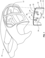
- Fig. 1 shows schematically a vehicle body 10 with a front wall 12, on which a sound insulation element 14 designed as a composite component is arranged.
- the sound insulation element 14 is fixed to the front wall 12 at least partially by fixing projections (not shown) which are formed integrally with the sound insulation element 14, for example, which, when the sound insulation element 14 is mounted, interact with a receiving opening in the vehicle body 10 or in the front wall 12, in which the fixing projections are placed.
- fixing projections not shown
- the sound insulation element 14 has a so-called mass-spring system, which comprises a plastic carrier layer 16 as a heavy or mass layer made of, for example, EVA/PE, PE, PP, EPDM, TPE, TPO and/or polyurethane foam, each of which is provided with a high weight proportion of up to 70 wt.% of a high-density mineral filler, for example feldspar, and a sound-damping layer 18 (see, for example, Fig. 6 ) made of a sound-absorbing material (e.g. polyurethane foam).
- a plastic carrier layer 16 as a heavy or mass layer made of, for example, EVA/PE, PE, PP, EPDM, TPE, TPO and/or polyurethane foam, each of which is provided with a high weight proportion of up to 70 wt.% of a high-density mineral filler, for example feldspar, and a sound-damping layer 18 (see, for example, Fig. 6 ) made of
- the sound insulation element 14 When installed according to Fig. 1 the sound insulation element 14 has a front side 20 facing the passenger compartment and a rear side 22 facing the front wall and resting against it.
- the front side 20 is formed by the outer surface 24 of the plastic carrier layer 16, while the rear side 22 is formed by the outer side 26 of the sound-damping layer 18.
- the plastic carrier layer 16 and the sound-damping layer 18 are connected to one another on their inner sides 28, 30 facing one another (see also Fig. 7 ).
- the sound insulation element 14 has several through-openings 32, 34, 36, 38, which are designed differently in this embodiment and are intended to show different types of passages of a sound insulation element.
- the other through-openings 34 shown in the figures are provided with sound-damping material along the hole edges of holes in the plastic carrier layer 16. The molding of the sound-damping material along these hole edges requires a certain amount of effort for positioning aid within the molding tool provided for molding the sound-damping material, as shown in the Fign. 3 and 4 shown.
- a cross section through a two-part mold 40 is shown in this embodiment, which has a first mold part 42 and a second mold part 44.
- the previously produced plastic carrier layer 16 is first placed in the mold space 46 of the mold 40, with the outer surface 24 of the plastic carrier layer on the The mold 40 is then moved together.
- four holes 48, 50, 52, 54 with hole edges 49, 51, 53, 55 are formed in the plastic carrier layer 16.
- a mold core 56 projects into the hole 54 and completely fills the hole 54.
- Mold cores 58, 60, 62 project into the holes 48, 50, 52, which are smaller in cross-section than the holes in question and thus keep free spaces 64, 66, 68 in the mold space 46 between themselves and the hole edges 49, 51, 53.
- the open spaces are therefore, as can be seen from the Fign. 3 and 4 can be seen, filled with sound-damping material when this material is introduced into the mold 40 via, for example, one (of in particular several) inlets 70.
- the mold cores 56, 58, 60, 62 ensure holes 57, 59, 61, 63 in the sound-damping layer 18 of the sound insulation element 14 that are aligned with the carrier layer holes 48, 50, 52, 54.
- hold-down projections 72 are arranged in the area of each hole 48, 50, 52, which protrude from the inside 28 of the plastic carrier layer 16 and which rest against the inside 74 of the second mold part 44 delimiting the mold space 46, or whose free ends 76 are arranged at a short distance from the mold part 44.
- the plastic carrier layer has 16 different structures in the area of said holes, as shown in the Fign. 3 and 4 or 6 and 7.
- the overhanging edge 80 in the hole 48 is aligned with the outer surface 24 of the plastic carrier layer 16, while the corresponding overhanging edge 82, 84 of the holes 50, 52 encloses the hole edges 51, 53 on both sides.
- additional hook structures or similar projections 86 protrude from the front side 20 of the plastic carrier layer 16, which are embedded in the sound-absorbing material and thus ensure additional hold of the sound-absorbing layer 18 on the front side 20 of the plastic carrier layer 16.
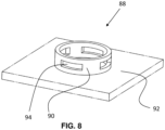
- Fig. 8 an alternative design of a hold-down projection 88 is shown.
- the hold-down projection 88 is designed as a circumferential collar 90 which runs around the opening in the plastic carrier layer indicated at 92.
- the collar 90 has openings 94 through which sound insulation material can reach close to the edge of the hole in the plastic carrier layer 92 or around the edge of the hole, as is the case for the hole designs according to Fig. 3 is shown.
- the hold-down projection 88 is embedded in this material.
Landscapes
- Engineering & Computer Science (AREA)
- Physics & Mathematics (AREA)
- Acoustics & Sound (AREA)
- Mechanical Engineering (AREA)
- Multimedia (AREA)
- Vehicle Interior And Exterior Ornaments, Soundproofing, And Insulation (AREA)
Claims (11)
- Elément d'isolation acoustique pour la paroi frontale d'une carrosserie de véhicule, disposée entre l'habitacle et le compartiment moteur, avec- un élément composite qui présente une couche de support en matière plastique (16) et une couche d'insonorisation (18) reliée à celle-ci,- dans lequel l'élément composite présentant un côté avant (20) tourné vers l'habitacle, vu dans son état de montage, formé par la surface extérieure (24) de la couche de support en matière plastique (16), et un côté arrière (22) s'appliquant contre la paroi frontale, qui est formé par le côté extérieur (26) de la couche d'insonorisation (18), opposé à la couche de support en matière plastique (16), et- au moins une première ouverture de passage (32, 34, 36, 38) dans l'élément composite,- dans lequel la première ouverture de passage (32, 34, 36, 38) présente un trou de couche de support (48, 50, 52, 54) realisé dans la couche de support en matière plastique (16) et ayant un bord de trou (49, 51, 53, 55), et un trou de couche d'insonorisation (57, 59, 61, 63) realisé dans la couche d'insonorisation (18) et ayant un bord de trou, et- dans lequel, sur le bord de trou (49, 51, 53, 55) du trou de la couche de support (48, 50, 52, 54) et/ou de manière décalée par rapport à celui-ci, sur la face intérieure (28) de la couche de support en matière plastique (16) opposée à la surface extérieure (24) de la couche de support en matière plastique (16) et donc tournée vers la couche d'insonorisation (18), fait saillie de celle-ci au moins une saillie de maintien vers le bas (72), qui est noyée dans le matériau d'insonorisation de la couche d'insonorisation (18) et dont les extrémités libres (76) opposées à la couche de support en matière plastique (16) sont sensiblement alignées avec la face extérieure (26) de la couche d'insonorisation (18) opposée à la couche de support en matière plastique (16).
- Elément d'isolation acoustique selon la revendication 1, caractérisé en ce que l'extrémité libre (76), opposée à la face intérieure (28) de la couche de support en matière plastique (16), de la au moins une saillie de maintien vers le bas (72) est recouverte d'un matériau d'insonorisation.
- Elément d'isolation acoustique selon la revendication 1 ou 2, caractérisé en ce que plusieurs saillies de-maintien vers le bas (72) sont disposées sur le pourtour du trou de la couche de support (48, 50, 52, 54).
- Elément d'isolation acoustique selon l'une des revendications 1 à 3, caractérisé en ce que la au moins une saillie de maintien vers le bas (72) est réalisée comme une saillie en forme de broche ou comme un dôme de maintien vers le bas
- Elément d'isolation acoustique selon la revendication 1 ou 2, caractérisé en ce que l'au moins une saillie de maintien vers le bas (72) est réalisée comme une collerette sur le pourtour du trou de la couche de support (48, 50, 52, 54) avec une paroi périphérique pourvue d'ajours.
- Elément d'isolation acoustique selon l'une des revendications 1 à 5, caractérisé en ce que du matériau d'insonorisation de la couche d'insonorisation (18) dépasse vers l'intérieur du bord de trou (49, 51, 53, 55) du trou de la couche de support (48, 50, 52, 54) et forme un bord de dépassement annulaire (80, 82, 84).
- Elément d'isolation acoustique selon la revendication 6, caractérisé en ce que le bord de dépassement (80, 82, 84) est aligné avec le côté extérieur (24) de la couche de support en matière plastique (16) ou s'étend le long d'au moins une partie du bord du trou (49, 51, 53, 55) du trou de la couche de support (48, 50, 52, 54) sur le côté extérieur (24) de la couche de support en matière plastique (16).
- Elément d'isolation acoustique selon l'une des revendications 1 à 7, caractérisé par au moins une deuxième ouverture de passage (32, 34, 36, 38) dans l'élément composite, qui comprend un trou de couche de support (48, 50, 52, 54) realisé dans la couche de support en matière plastique (16) et un trou de couche d'isolation acoustique (57, 59, 61, 63) realisé dans la couche d'insonorisation (18), les deux trous ayant des bords de trou alignés l'un avec l'autre.
- Elément de support pour un élément d'isolation acoustique selon la revendication 1, destiné à être disposé sur une paroi frontale d'une carrosserie de véhicule prévue entre le compartiment moteur et l'habitacle, avec- une couche de support en matière plastique (16) avec une face extérieure et avec une face intérieure, sur laquelle peut être appliqué, dans un outil de moulage présentant au moins deux parties d'outil de moulage, un matériau d'insonorisation d'une couche d'insonorisation (18) de l'élément composite d'isolation acoustique,- au moins un premier trou de couche de support avec un bord de trou realisé dans la couche de support en matière plastique (16), et- au moins une saillie de maintien vers le bas (72) disposée sur le bord du trou et/ou décalée par rapport à celui-ci, qui fait saillie de la couche de support en matière plastique (16) et dépassant de la face intérieure de la couche de support en matière plastique (16), l'extrémité de la au moins une saillie de maintien vers le bas (72) opposée à la face intérieure de la couche de support en matière plastique (16) étant appropriée et destinée à la mise en contact d'une deuxième partie d'outil de moulage pour maintenir la couche de support en matière plastique (16) en appui sur une première partie d'outil de moulage dans la zone du bord de trou du trou de la première couche de support.
- Elément de support selon la revendication 9, caractérisé en ce que le premier trou de la couche de support en matière plastique (16) est prévu pour la pénétration qui s'effectue avec un jeu radial par rapport au bord du trou du premier trou de la couche de support au moyen d'un noyau d'outil de moulage, en particulier au moyen d'un noyau d'outil de moulage qui est disposé sur la première ou la deuxième partie d'outil de moulage pour mouler le matériau d'insonorisation à la face arrière de la couche de support en matière plastique (16).
- Elément de support selon la revendication 9 ou 10, caractérisé en ce que la au moins une saillie de maintien vers le bas (72) est réalisée comme indiqué dans l'une des revendications 1 à 8 et/ou en ce que la couche de support en matière plastique (16) est réalisée comme indiqué dans l'une des revendications 1 à 8 et/ou en ce que la couche de support en matière plastique (16) est pourvue d'une couche d'insonorisation (18) ou de matériau d'insonorisation comme indiqué dans l'une des revendications 1 à 8.
Applications Claiming Priority (2)
| Application Number | Priority Date | Filing Date | Title |
|---|---|---|---|
| DE102018132726 | 2018-12-18 | ||
| PCT/EP2019/084363 WO2020126651A1 (fr) | 2018-12-18 | 2019-12-10 | Élément d'isolation contre le bruit pour la paroi frontale d'une carrosserie de véhicule et élément support pour un tel élément d'isolation contre le bruit |
Publications (2)
| Publication Number | Publication Date |
|---|---|
| EP3898340A1 EP3898340A1 (fr) | 2021-10-27 |
| EP3898340B1 true EP3898340B1 (fr) | 2025-01-15 |
Family
ID=69147582
Family Applications (1)
| Application Number | Title | Priority Date | Filing Date |
|---|---|---|---|
| EP19832848.6A Active EP3898340B1 (fr) | 2018-12-18 | 2019-12-10 | Élément d'isolation contre le bruit pour la paroi frontale d'une carrosserie de véhicule et élément support pour un tel élément d'isolation contre le bruit |
Country Status (5)
| Country | Link |
|---|---|
| US (1) | US12065084B2 (fr) |
| EP (1) | EP3898340B1 (fr) |
| JP (1) | JP7480148B2 (fr) |
| CN (1) | CN113490616B (fr) |
| WO (1) | WO2020126651A1 (fr) |
Families Citing this family (2)
| Publication number | Priority date | Publication date | Assignee | Title |
|---|---|---|---|---|
| EP4101740B1 (fr) * | 2018-05-23 | 2025-10-29 | Sika Technology AG | Élément d'isolation et procédé d'isolation d'un élément de structure |
| DE102021101921A1 (de) * | 2021-01-28 | 2022-07-28 | Adler Pelzer Holding Gmbh | Schallisolierung mit mehrschichtiger Faser-Isolation; und Verfahren zu deren Herstellung |
Family Cites Families (39)
| Publication number | Priority date | Publication date | Assignee | Title |
|---|---|---|---|---|
| DE33284C (de) | C. STEFFEN in Wien und R. RACYMäCKERS in Tirlemont, Belgien | Verfahren zur Gewinnung von weifsem Zucker aus Rohzuckerfüllmassen | ||
| DE33098C (de) | F. mackinlay in London | Vorrichtung zur Veränderung der Spurweite bei Eisenbahnwagen | ||
| DE32571C (de) | C. L. LASCH in Reudnitz-Leipzig, Kohlgartenstr. Nr. 1 | Maschine zum Heften von Pappschachteln mittelst Drahtklammern | ||
| JPS63188544A (ja) | 1987-01-28 | 1988-08-04 | Kasai Kogyo Co Ltd | 自動車用インシユレ−タ |
| JPH0267823U (fr) | 1988-07-27 | 1990-05-23 | ||
| JPH0343051U (fr) * | 1989-09-06 | 1991-04-23 | ||
| JP2991321B2 (ja) | 1994-04-15 | 1999-12-20 | 株式会社イノアックコーポレーション | 表皮付き発泡体を表面に有するプラスチック成形品およびその製造方法 |
| US5588810A (en) | 1995-09-01 | 1996-12-31 | Bristol Compressors, Inc. | Low noise refrigerant compressor |
| DE29601491U1 (de) | 1996-01-29 | 1996-06-05 | Siemens AG, 80333 München | Haushaltsgerät-Pumpenantrieb mit einem selbstanlaufenden Einphasen-Synchronmotor |
| DE59703529D1 (de) | 1996-03-20 | 2001-06-21 | Rxs Ges Fuer Vermoegensverwalt | Kabelmuffe |
| US5831225A (en) * | 1996-07-26 | 1998-11-03 | Cascade Engineering, Inc. | System and method for fastening insulating layers to a support structure |
| KR100288872B1 (en) | 1998-01-20 | 2001-02-12 | Samsung Electronics Co Ltd | Noise reduction apparatus for air conditioner outdoor unit |
| ES2205769T3 (es) * | 1998-02-11 | 2004-05-01 | Cascade Engineering, Inc. | Esterilla de amortiguacion del sonido con fijacion de moldeo integral. |
| JP2001010419A (ja) | 1999-07-01 | 2001-01-16 | Nishikawa Kasei Co Ltd | 自動車のダッシュインシュレータ |
| DE10235091C1 (de) | 2002-07-31 | 2003-11-06 | Carcoustics Tech Ct Gmbh | Schallisolierendes Verbundteil und Verfahren zu dessen Herstellung |
| DE10246998A1 (de) | 2002-10-02 | 2004-04-15 | Sai Automotive Sal Gmbh | Stirnwand für ein Kraftfahrzeug |
| US7070848B2 (en) * | 2002-10-21 | 2006-07-04 | Cascade Engineering, Inc. | Vehicle acoustic barrier |
| CA2475280A1 (fr) | 2003-07-21 | 2005-01-21 | Villa Olympic Inc. | Couvercle attenuateur de son pour compresseurs de climatiseurs domestiques |
| DE10334274B3 (de) | 2003-07-25 | 2005-03-03 | Carcoustics Tech Center Gmbh | Schallisolierendes Verbundteil und Verfahren zu dessen Herstellung |
| DE102004008165A1 (de) | 2004-02-10 | 2005-08-25 | Ekkehard Rath | Zahnriemen |
| DE202004008165U1 (de) * | 2004-05-19 | 2005-09-29 | Carcoustics Tech Center Gmbh | Schallisolierendes Bauteil aus hochgefülltem thermoplastischen Elastomer auf Basis von Styrol |
| JP2006327528A (ja) | 2005-05-30 | 2006-12-07 | Tokai Rubber Ind Ltd | フードサイレンサ |
| JP2007106300A (ja) * | 2005-10-14 | 2007-04-26 | Inoac Corp | 車両用遮音装置 |
| US20070137926A1 (en) | 2005-12-15 | 2007-06-21 | Lear Corporation | Acoustical component for enhancing sound absorption properties while preserving barrier performance in a vehicle interior |
| JP2007198312A (ja) | 2006-01-27 | 2007-08-09 | Tokai Rubber Ind Ltd | 防音カバー |
| US20070218790A1 (en) * | 2006-03-16 | 2007-09-20 | Am General Llc | Composite insulation |
| US20080099275A1 (en) | 2006-10-31 | 2008-05-01 | Robert Vaughan Seel | Sound Attenuation Enclosure |
| DE102007020832B4 (de) | 2007-05-02 | 2009-02-26 | Bayer Materialscience Ag | Leichte, schallisolierende Verkleidung für ein Karosserieteil eines Kraftfahrzeuges und Verfahren zu deren Herstellung |
| US8337975B2 (en) * | 2009-01-21 | 2012-12-25 | Nissan North America, Inc. | Vehicle panel |
| CN201646596U (zh) | 2009-12-16 | 2010-11-24 | 浙江吉利汽车研究院有限公司 | 一种汽车前围隔音垫 |
| EP2786851B1 (fr) | 2013-04-03 | 2019-06-05 | Faurecia Automotive Industrie | Procédé de fabrication d'un élément d'insonorisation, en particulier pour un véhicule automobile |
| DE102013006300A1 (de) | 2013-04-12 | 2014-10-16 | Parat Beteiligungs Gmbh | Strukturbauteil und Verfahren zur Herstellung eines Strukturbauteils |
| DE102015104377B4 (de) | 2015-03-24 | 2020-04-02 | Lisa Dräxlmaier GmbH | Kontaktteil und Verfahren zum Herstellen eines Kontaktteils |
| JP2016205344A (ja) | 2015-04-28 | 2016-12-08 | ダイキン工業株式会社 | 空気調和機用圧縮機の防音カバー |
| BR112019020210B1 (pt) | 2017-04-19 | 2024-03-05 | Adler Pelzer Holding Gmbh | Elemento de isolamento de som para a parede frontal de uma carroceria de automóvel |
| DE102017121459B4 (de) | 2017-09-15 | 2024-03-14 | Auto-Kabel Management Gmbh | Kabelabdichtung sowie Anordnung mit einem Gehäuse |
| DE102020104489B4 (de) | 2020-02-20 | 2024-12-24 | Adler Pelzer Holding Gmbh | Vorrichtung zur Befestigung eines Fahrzeugbauteils in und/oder an einem Fahrzeug |
| DE102020105994A1 (de) | 2020-03-05 | 2021-09-09 | Te Connectivity Germany Gmbh | Robustes, hochfrequenz-geeignetes elektrisches Terminal |
| EP4191803A1 (fr) | 2021-12-03 | 2023-06-07 | Neutrik AG | Elément de déverrouillage et connecteur électrique l'utilisant |
-
2019
- 2019-12-10 EP EP19832848.6A patent/EP3898340B1/fr active Active
- 2019-12-10 JP JP2021534997A patent/JP7480148B2/ja active Active
- 2019-12-10 WO PCT/EP2019/084363 patent/WO2020126651A1/fr not_active Ceased
- 2019-12-10 CN CN201980092485.2A patent/CN113490616B/zh active Active
- 2019-12-10 US US17/416,353 patent/US12065084B2/en active Active
Also Published As
| Publication number | Publication date |
|---|---|
| US12065084B2 (en) | 2024-08-20 |
| WO2020126651A1 (fr) | 2020-06-25 |
| US20220073013A1 (en) | 2022-03-10 |
| JP2022514002A (ja) | 2022-02-09 |
| JP7480148B2 (ja) | 2024-05-09 |
| CN113490616A (zh) | 2021-10-08 |
| EP3898340A1 (fr) | 2021-10-27 |
| CN113490616B (zh) | 2025-06-24 |
Similar Documents
| Publication | Publication Date | Title |
|---|---|---|
| DE112018001448B4 (de) | Kabelbaumanordnungsstruktur | |
| DE102020104489B4 (de) | Vorrichtung zur Befestigung eines Fahrzeugbauteils in und/oder an einem Fahrzeug | |
| WO2013076066A1 (fr) | Console centrale de véhicules et procédé de fabrication de ladite console centrale | |
| EP3898340B1 (fr) | Élément d'isolation contre le bruit pour la paroi frontale d'une carrosserie de véhicule et élément support pour un tel élément d'isolation contre le bruit | |
| WO2003097431A1 (fr) | Composant leger pour elements de support de vehicules automobiles | |
| DE102007053995B4 (de) | Verfahren zur Herstellung einer Instrumententafel eines Kraftfahrzeugs | |
| DE112014006868B4 (de) | Motorabdeckung zur Verformung in eine spezifische Richtung | |
| DE102010040021A1 (de) | Türinnenverkleidung für Fahrzeugtüren | |
| DE102012021542B4 (de) | Struktur eines Instrumententrägerteils | |
| EP1973772B1 (fr) | Élément de dessous de caisse de véhicule notamment habillage de dessous de caisse ou habillage de passage de roue | |
| EP1854681A2 (fr) | Conduit d'air de véhicule automobile | |
| DE102012022899A1 (de) | Verbindungselement zur Abstützung eines Stoßfängers eines Kraftfahrzeuges gegenüber einem Montageträger, Baueinheit mit einem solchen Verbindungselement sowie Verfahren zur Herstellung eines Verbindungselements | |
| EP2022909B1 (fr) | Boite d'attente | |
| DE102018105240B4 (de) | Stossabsorber | |
| EP1331075A1 (fr) | Ensemble comprenant boítier et unité d'un volet | |
| EP2563620B1 (fr) | Élément d'habillage intérieur de véhicule, et procédé de production d'un élément d'habillage intérieur de véhicule | |
| DE102017208230A1 (de) | Befestigen eines Airbags im Fahrzeug | |
| DE102011017235A1 (de) | Halteanordnung eines Innenverkleidungselements an einem Rohbauelement eines Kraftwagens sowie Baukastensystem zur Herstellung einer solchen Halteanordnung | |
| EP2558335B1 (fr) | Système d'airbag et procédé de fabrication de celui-ci | |
| DE102016206611B4 (de) | Kabeltülle und Verfahren zur Herstellung einer Kabeltülle | |
| DE102019124086B4 (de) | Verfahren zum herstellen einer abdeckeinrichtung und abdeckeinrichtung | |
| DE102010055953A1 (de) | Stoßfängeranordnung und Verfahren zum Herstellen einer solchen Stoßfängeranordnung | |
| EP3423307B1 (fr) | Réceptacle en dessous du toit d'un véhicule | |
| EP3548244B1 (fr) | Dispositif et procédé de traitement d'une couverture ainsi qu'agencement pour un toit de véhicule et toit du véhicule pour un véhicule à moteur | |
| DE102011118690A1 (de) | Fronthaube für einen Personenkraftwagen sowie Verfahren zum Herstellen einer solchen Fronthaube |
Legal Events
| Date | Code | Title | Description |
|---|---|---|---|
| STAA | Information on the status of an ep patent application or granted ep patent |
Free format text: STATUS: UNKNOWN |
|
| STAA | Information on the status of an ep patent application or granted ep patent |
Free format text: STATUS: THE INTERNATIONAL PUBLICATION HAS BEEN MADE |
|
| PUAI | Public reference made under article 153(3) epc to a published international application that has entered the european phase |
Free format text: ORIGINAL CODE: 0009012 |
|
| STAA | Information on the status of an ep patent application or granted ep patent |
Free format text: STATUS: REQUEST FOR EXAMINATION WAS MADE |
|
| 17P | Request for examination filed |
Effective date: 20210630 |
|
| AK | Designated contracting states |
Kind code of ref document: A1 Designated state(s): AL AT BE BG CH CY CZ DE DK EE ES FI FR GB GR HR HU IE IS IT LI LT LU LV MC MK MT NL NO PL PT RO RS SE SI SK SM TR |
|
| DAV | Request for validation of the european patent (deleted) | ||
| DAX | Request for extension of the european patent (deleted) | ||
| P01 | Opt-out of the competence of the unified patent court (upc) registered |
Effective date: 20230527 |
|
| GRAP | Despatch of communication of intention to grant a patent |
Free format text: ORIGINAL CODE: EPIDOSNIGR1 |
|
| STAA | Information on the status of an ep patent application or granted ep patent |
Free format text: STATUS: GRANT OF PATENT IS INTENDED |
|
| INTG | Intention to grant announced |
Effective date: 20240619 |
|
| GRAS | Grant fee paid |
Free format text: ORIGINAL CODE: EPIDOSNIGR3 |
|
| GRAJ | Information related to disapproval of communication of intention to grant by the applicant or resumption of examination proceedings by the epo deleted |
Free format text: ORIGINAL CODE: EPIDOSDIGR1 |
|
| GRAL | Information related to payment of fee for publishing/printing deleted |
Free format text: ORIGINAL CODE: EPIDOSDIGR3 |
|
| STAA | Information on the status of an ep patent application or granted ep patent |
Free format text: STATUS: REQUEST FOR EXAMINATION WAS MADE |
|
| INTC | Intention to grant announced (deleted) | ||
| GRAP | Despatch of communication of intention to grant a patent |
Free format text: ORIGINAL CODE: EPIDOSNIGR1 |
|
| STAA | Information on the status of an ep patent application or granted ep patent |
Free format text: STATUS: GRANT OF PATENT IS INTENDED |
|
| GRAA | (expected) grant |
Free format text: ORIGINAL CODE: 0009210 |
|
| STAA | Information on the status of an ep patent application or granted ep patent |
Free format text: STATUS: THE PATENT HAS BEEN GRANTED |
|
| INTG | Intention to grant announced |
Effective date: 20241203 |
|
| AK | Designated contracting states |
Kind code of ref document: B1 Designated state(s): AL AT BE BG CH CY CZ DE DK EE ES FI FR GB GR HR HU IE IS IT LI LT LU LV MC MK MT NL NO PL PT RO RS SE SI SK SM TR |
|
| REG | Reference to a national code |
Ref country code: CH Ref legal event code: EP Ref country code: GB Ref legal event code: FG4D Free format text: NOT ENGLISH |
|
| REG | Reference to a national code |
Ref country code: DE Ref legal event code: R096 Ref document number: 502019012833 Country of ref document: DE |
|
| REG | Reference to a national code |
Ref country code: IE Ref legal event code: FG4D Free format text: LANGUAGE OF EP DOCUMENT: GERMAN |
|
| REG | Reference to a national code |
Ref country code: NL Ref legal event code: MP Effective date: 20250115 |
|
| PG25 | Lapsed in a contracting state [announced via postgrant information from national office to epo] |
Ref country code: NL Free format text: LAPSE BECAUSE OF FAILURE TO SUBMIT A TRANSLATION OF THE DESCRIPTION OR TO PAY THE FEE WITHIN THE PRESCRIBED TIME-LIMIT Effective date: 20250115 |
|
| PG25 | Lapsed in a contracting state [announced via postgrant information from national office to epo] |
Ref country code: RS Free format text: LAPSE BECAUSE OF FAILURE TO SUBMIT A TRANSLATION OF THE DESCRIPTION OR TO PAY THE FEE WITHIN THE PRESCRIBED TIME-LIMIT Effective date: 20250415 |
|
| PG25 | Lapsed in a contracting state [announced via postgrant information from national office to epo] |
Ref country code: FI Free format text: LAPSE BECAUSE OF FAILURE TO SUBMIT A TRANSLATION OF THE DESCRIPTION OR TO PAY THE FEE WITHIN THE PRESCRIBED TIME-LIMIT Effective date: 20250115 |
|
| PG25 | Lapsed in a contracting state [announced via postgrant information from national office to epo] |
Ref country code: PL Free format text: LAPSE BECAUSE OF FAILURE TO SUBMIT A TRANSLATION OF THE DESCRIPTION OR TO PAY THE FEE WITHIN THE PRESCRIBED TIME-LIMIT Effective date: 20250115 |
|
| PG25 | Lapsed in a contracting state [announced via postgrant information from national office to epo] |
Ref country code: ES Free format text: LAPSE BECAUSE OF FAILURE TO SUBMIT A TRANSLATION OF THE DESCRIPTION OR TO PAY THE FEE WITHIN THE PRESCRIBED TIME-LIMIT Effective date: 20250115 |
|
| REG | Reference to a national code |
Ref country code: LT Ref legal event code: MG9D |
|
| PG25 | Lapsed in a contracting state [announced via postgrant information from national office to epo] |
Ref country code: IS Free format text: LAPSE BECAUSE OF FAILURE TO SUBMIT A TRANSLATION OF THE DESCRIPTION OR TO PAY THE FEE WITHIN THE PRESCRIBED TIME-LIMIT Effective date: 20250515 Ref country code: NO Free format text: LAPSE BECAUSE OF FAILURE TO SUBMIT A TRANSLATION OF THE DESCRIPTION OR TO PAY THE FEE WITHIN THE PRESCRIBED TIME-LIMIT Effective date: 20250415 |
|
| PG25 | Lapsed in a contracting state [announced via postgrant information from national office to epo] |
Ref country code: HR Free format text: LAPSE BECAUSE OF FAILURE TO SUBMIT A TRANSLATION OF THE DESCRIPTION OR TO PAY THE FEE WITHIN THE PRESCRIBED TIME-LIMIT Effective date: 20250115 |
|
| PG25 | Lapsed in a contracting state [announced via postgrant information from national office to epo] |
Ref country code: LV Free format text: LAPSE BECAUSE OF FAILURE TO SUBMIT A TRANSLATION OF THE DESCRIPTION OR TO PAY THE FEE WITHIN THE PRESCRIBED TIME-LIMIT Effective date: 20250115 Ref country code: PT Free format text: LAPSE BECAUSE OF FAILURE TO SUBMIT A TRANSLATION OF THE DESCRIPTION OR TO PAY THE FEE WITHIN THE PRESCRIBED TIME-LIMIT Effective date: 20250515 |
|
| PG25 | Lapsed in a contracting state [announced via postgrant information from national office to epo] |
Ref country code: BG Free format text: LAPSE BECAUSE OF FAILURE TO SUBMIT A TRANSLATION OF THE DESCRIPTION OR TO PAY THE FEE WITHIN THE PRESCRIBED TIME-LIMIT Effective date: 20250115 Ref country code: GR Free format text: LAPSE BECAUSE OF FAILURE TO SUBMIT A TRANSLATION OF THE DESCRIPTION OR TO PAY THE FEE WITHIN THE PRESCRIBED TIME-LIMIT Effective date: 20250416 |
|
| PG25 | Lapsed in a contracting state [announced via postgrant information from national office to epo] |
Ref country code: SE Free format text: LAPSE BECAUSE OF FAILURE TO SUBMIT A TRANSLATION OF THE DESCRIPTION OR TO PAY THE FEE WITHIN THE PRESCRIBED TIME-LIMIT Effective date: 20250115 |
|
| PG25 | Lapsed in a contracting state [announced via postgrant information from national office to epo] |
Ref country code: SM Free format text: LAPSE BECAUSE OF FAILURE TO SUBMIT A TRANSLATION OF THE DESCRIPTION OR TO PAY THE FEE WITHIN THE PRESCRIBED TIME-LIMIT Effective date: 20250115 |
|
| PG25 | Lapsed in a contracting state [announced via postgrant information from national office to epo] |
Ref country code: DK Free format text: LAPSE BECAUSE OF FAILURE TO SUBMIT A TRANSLATION OF THE DESCRIPTION OR TO PAY THE FEE WITHIN THE PRESCRIBED TIME-LIMIT Effective date: 20250115 |
|
| REG | Reference to a national code |
Ref country code: DE Ref legal event code: R097 Ref document number: 502019012833 Country of ref document: DE |
|
| PG25 | Lapsed in a contracting state [announced via postgrant information from national office to epo] |
Ref country code: CZ Free format text: LAPSE BECAUSE OF FAILURE TO SUBMIT A TRANSLATION OF THE DESCRIPTION OR TO PAY THE FEE WITHIN THE PRESCRIBED TIME-LIMIT Effective date: 20250115 Ref country code: EE Free format text: LAPSE BECAUSE OF FAILURE TO SUBMIT A TRANSLATION OF THE DESCRIPTION OR TO PAY THE FEE WITHIN THE PRESCRIBED TIME-LIMIT Effective date: 20250115 |
|
| PG25 | Lapsed in a contracting state [announced via postgrant information from national office to epo] |
Ref country code: RO Free format text: LAPSE BECAUSE OF FAILURE TO SUBMIT A TRANSLATION OF THE DESCRIPTION OR TO PAY THE FEE WITHIN THE PRESCRIBED TIME-LIMIT Effective date: 20250115 |
|
| PG25 | Lapsed in a contracting state [announced via postgrant information from national office to epo] |
Ref country code: SK Free format text: LAPSE BECAUSE OF FAILURE TO SUBMIT A TRANSLATION OF THE DESCRIPTION OR TO PAY THE FEE WITHIN THE PRESCRIBED TIME-LIMIT Effective date: 20250115 |
|
| PLBE | No opposition filed within time limit |
Free format text: ORIGINAL CODE: 0009261 |
|
| STAA | Information on the status of an ep patent application or granted ep patent |
Free format text: STATUS: NO OPPOSITION FILED WITHIN TIME LIMIT |
|
| 26N | No opposition filed |
Effective date: 20251016 |
|
| PGFP | Annual fee paid to national office [announced via postgrant information from national office to epo] |
Ref country code: GB Payment date: 20251229 Year of fee payment: 7 |
|
| PGFP | Annual fee paid to national office [announced via postgrant information from national office to epo] |
Ref country code: IT Payment date: 20251210 Year of fee payment: 7 |
|
| PGFP | Annual fee paid to national office [announced via postgrant information from national office to epo] |
Ref country code: FR Payment date: 20251230 Year of fee payment: 7 |
|
| PGFP | Annual fee paid to national office [announced via postgrant information from national office to epo] |
Ref country code: DE Payment date: 20251231 Year of fee payment: 7 |