EP3898341B1 - Elektronische architektur für ein bordsystem - Google Patents
Elektronische architektur für ein bordsystem Download PDFInfo
- Publication number
- EP3898341B1 EP3898341B1 EP19813369.6A EP19813369A EP3898341B1 EP 3898341 B1 EP3898341 B1 EP 3898341B1 EP 19813369 A EP19813369 A EP 19813369A EP 3898341 B1 EP3898341 B1 EP 3898341B1
- Authority
- EP
- European Patent Office
- Prior art keywords
- actuators
- sensors
- architecture
- data
- architecture according
- Prior art date
- Legal status (The legal status is an assumption and is not a legal conclusion. Google has not performed a legal analysis and makes no representation as to the accuracy of the status listed.)
- Active
Links
Images


Classifications
-
- H—ELECTRICITY
- H04—ELECTRIC COMMUNICATION TECHNIQUE
- H04L—TRANSMISSION OF DIGITAL INFORMATION, e.g. TELEGRAPHIC COMMUNICATION
- H04L67/00—Network arrangements or protocols for supporting network services or applications
- H04L67/01—Protocols
- H04L67/12—Protocols specially adapted for proprietary or special-purpose networking environments, e.g. medical networks, sensor networks, networks in vehicles or remote metering networks
-
- H—ELECTRICITY
- H04—ELECTRIC COMMUNICATION TECHNIQUE
- H04L—TRANSMISSION OF DIGITAL INFORMATION, e.g. TELEGRAPHIC COMMUNICATION
- H04L12/00—Data switching networks
- H04L12/28—Data switching networks characterised by path configuration, e.g. LAN [Local Area Networks] or WAN [Wide Area Networks]
- H04L12/40—Bus networks
- H04L12/40052—High-speed IEEE 1394 serial bus
- H04L12/40078—Bus configuration
-
- H—ELECTRICITY
- H04—ELECTRIC COMMUNICATION TECHNIQUE
- H04L—TRANSMISSION OF DIGITAL INFORMATION, e.g. TELEGRAPHIC COMMUNICATION
- H04L12/00—Data switching networks
- H04L12/28—Data switching networks characterised by path configuration, e.g. LAN [Local Area Networks] or WAN [Wide Area Networks]
- H04L12/40—Bus networks
- H04L12/40169—Flexible bus arrangements
-
- H—ELECTRICITY
- H04—ELECTRIC COMMUNICATION TECHNIQUE
- H04L—TRANSMISSION OF DIGITAL INFORMATION, e.g. TELEGRAPHIC COMMUNICATION
- H04L12/00—Data switching networks
- H04L12/28—Data switching networks characterised by path configuration, e.g. LAN [Local Area Networks] or WAN [Wide Area Networks]
- H04L12/40—Bus networks
- H04L12/407—Bus networks with decentralised control
- H04L12/413—Bus networks with decentralised control with random access, e.g. carrier-sense multiple-access with collision detection [CSMA-CD]
-
- H—ELECTRICITY
- H04—ELECTRIC COMMUNICATION TECHNIQUE
- H04L—TRANSMISSION OF DIGITAL INFORMATION, e.g. TELEGRAPHIC COMMUNICATION
- H04L12/00—Data switching networks
- H04L12/28—Data switching networks characterised by path configuration, e.g. LAN [Local Area Networks] or WAN [Wide Area Networks]
- H04L12/40—Bus networks
- H04L2012/40267—Bus for use in transportation systems
- H04L2012/40273—Bus for use in transportation systems the transportation system being a vehicle
Definitions
- the present invention relates to an electronic architecture for an embedded system. It applies in particular to a system ensuring the management of the functions of a motor vehicle. It applies in particular to all types of motor vehicles and applies more generally to any distributed cyber-physical system.
- the main objective of the electronic architecture of a motor vehicle is to enable the correct performance of the vehicle's services, i.e. its functions (seen by the user or not).
- each function requires input data provided by one or more sensors or computers, a means of processing this data, and generates output data, controlling one or more actuators or serving one or more computers.
- actuators can also send data and sensors can receive data.
- the number of functions has increased sharply since the beginnings of the automobile, for safety, comfort or for example reliability.
- these functions can be of very different natures, whether in terms of necessary calculations or data manipulated. For example, a function could simply consist of making an engine react when a sensor is pressed by the driver, but there are also complex driver assistance systems that can rely on several high-speed camera streams in order to detect obstacles in front of the vehicle.
- a very important point is also linked to the fact that they do not have the same sensitivity to safety and security. Thus, if certain functions are not critical to the proper functioning of the vehicle, the failure of other functions can endanger the lives of the occupants (triggering an airbag on the highway, for example). Thus, controlling the time taken to obtain data, calculations and the distribution of commands to the actuators is a very important point, as is the security of this information.
- Several points related to integration into the vehicle must also be considered. Firstly, the size and weight of the systems are important issues. They must be as small as possible in order to maintain vehicles of reasonable size, and whose energy consumption is controlled. Another point related to the system footprint concerns the interconnection of sensors, actuators and computing resources: the wiring must be as small as possible for the same reasons.
- the economic cost of the architecture must be considered. It must be sized as precisely as possible so as not to increase the price of the vehicle too significantly. However, this optimization of the manufacturing cost must not prevent the architecture from being able to meet the performance needs of future functions that will have to be integrated into the vehicle, and the integration of future sensors and actuators (high-resolution cameras, etc.). Indeed, redeveloping an architecture from scratch is also very expensive.
- a technical problem to be solved is to be able to offer an electronic architecture capable of evolving and ensuring the execution of current and future functions of a vehicle and therefore to provide sufficient computing power and interconnection means, as well as safety, security and time control properties. These good properties must be provided with manageable complexity and size.
- ECU Electronic Control Units
- Each ECU is composed of a computing resource (processor or microcontroller), generally cut to the smallest detail for cost reasons, with its memories, its inputs/outputs, etc.
- processor or microcontroller a computing resource
- the present invention is within the framework of vehicle architectures using ECUs, which represents all current vehicles.
- the first electronic architectures were completely distributed. They consisted of introducing dedicated subsystems for each vehicle function, including their sensors, actuators, computers, and interconnecting cables.
- Links are also available to transmit video, audio, Ethernet traffic, and communication protocols via different channels.
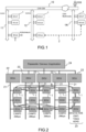
- FIG. 1 represents a high-level vision of a current electronic architecture for the management of a motor vehicle.
- Various ECUs 1 are grouped on a multiplexed CAN bus (“Controller Area Network”) 11, 12, 1N, a dedicated ECU 10 ( CAN Gateway ) allowing to go from one CAN bus to another while respecting the time constraints.
- This regular architecture is however undermined by the addition of functions requiring, for example, higher data rates than CAN allows.
- CAN Gateway CAN Gateway
- FIG. 2 An example of architecture by functional domains is illustrated by the Figure 2
- the general idea is to reuse the vision of the Figure 1 , but to strongly group the ECUs 1 belonging to the same functional domain around a dedicated multiplexed bus 21, adapted to the constraints of the domain, the ECUs and the buses being controlled for each domain by a domain control unit 22 ("Domain Controller Unit", DCU).
- DCU Domain Controller Unit
- the introduction of a level of hierarchy per domain, the domain controller, as well as an application server/gateway 24 to link the domains to the multimedia and connectivity aspects is the path currently being explored by manufacturers and equipment manufacturers.
- a weakness lies in the fact that there is a fixed assignment of logic and software functions to a hardware ECU and an optimization of this ECU for its function.
- any modification of the architecture will not be easy. For example, adding a domain or adding a new function in a domain requiring the outputs of a sensor or the control of an actuator not part of the domain will require complex communications to be set up.
- RACE Robot and reliable Automotive Computing Environment for future eCars
- CPC Centralized Platform Computer
- VCC Vehicle Control Computers
- the CPC is connected to intelligent sensors/actuators capable of managing themselves via an Ethernet network.
- the RACE architecture resembles the architecture based on functional domains except that the domains become more localized in the vehicle and not grouped by high-level functions.
- the RACE architecture remains highly hierarchical at the control level and assumes the presence of these new intelligent sensors/actuators that manage their domain, including the sensor/actuator control loops.
- One of the advantages of the RACE architecture is that there is a fairly significant decoupling between software and hardware in the sense that the allocation of hardware to a particular domain is weak. However, there remains a strong coupling between the local control loops operating on the intelligent sensors/actuators and their location in the vehicle. Thus, the architecture is not completely centralized, as a significant part of the control is local.
- US 2007/0113070 A1 discloses an electronic architecture embedded in a system ensuring the management of the functions of said system. This document does not disclose the distribution of commands to actuators of several functional areas.
- At least one of said interface modules aggregates signals from sensors of several functional areas and distributes commands to actuators of several functional areas, said sensors and actuators being located in the geographical area assigned to said at least one module.
- At least one of said interface modules also aggregates signals from at least one of said actuators and/or distributes signals to at least one of said sensors.
- said central computer is composed of a motherboard and calculation subsystems, each subsystem comprising one or more processors coupled to a private memory capable of executing several software partitions, said subsystems communicating with each other and with said communication network by means of an interconnection infrastructure installed on said motherboard.
- Said architecture comprises, for example, a centralized data management functional block allowing access to the data in the memories present in the computer and in said modules, said functional block providing the various components of said architecture with unified access to the data linked to the sensors and actuators distributed in said system as well as to the data generated by said calculation subsystems.
- Said functional block is for example implemented by means of a distributed memory service virtually shared between said computer and said modules, so that all communications between said central computer and said sensors and actuators pass through said virtual memory and so that the memories distributed in said architecture and all the sensors and actuators appear to said central computer as a single shared memory.
- Said functional block can make it possible to secure access to data through the use of attributes associated with the data.
- Said architecture includes, for example, a functional block enabling synchronization between said calculation subsystems.
- Said architecture includes, for example, a functional block making it possible to ensure and support services linked to the operational safety of said system.
- said processor carries out for example translations of communication protocols of said interfaces to exchange said data with said central computer according to a single protocol.
- Said architecture comprises, for example, at least one gateway capable of connecting said communication network to at least one other communication network.
- It comprises, for example, a secondary computer communicating with said communication network by means of said gateway (35), said secondary computer controlling functions connected to said other network.
- It comprises for example a combination of techniques in addition to the execution of several software partitions, said combination forming virtual domains, each virtual domain covering at least one of said partitions processing the interface modules (33) of a group of sensors and actuators.
- Said combination comprises for example a combination of data transfer segregation mechanisms in said real-time communications network. Said combination is for example based on data attributes placed by said interface modules.
- Communications between said central computer and said interface modules are for example controlled by said computer.
- Said architecture comprises, for example, a subsystem for managing high-speed transmission input and output signals, connected to the interconnection infrastructure of said motherboard, said subsystem being composed of one or more daughter cards and ensuring the function of an interface module between high-speed transmission sensors and/or actuators and said central computer.
- the said communication network is of the deterministic Ethernet type, for example it is of the Ethernet TSN type.
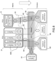
- FIG. 3b illustrates the principle of an electronic architecture for an automobile according to the invention, with regard to the Figure 3a illustrating an architecture according to the prior art.
- Figure 3a takes up the architecture according to the prior art of the Figure 2 but by illustrating the processing and functions controlled by the ECUs by giving an indication of the geographical location of the latter in the vehicle 30.
- a single multiplexed bus 11 is represented, around which all the ECUs 1 represented are grouped.
- the functions controlled by the ECUs are indicated in boxes 1'.
- Figure 3b presents an example of architecture which essentially incorporates the functions of the Figure 3a .
- the invention proposes a shared and centralized computing architecture for managing the functions of a vehicle.
- the ECUs and the multiplexed buses of the Figure 3a are replaced by a central physical computer 31 and by a real-time network connecting interface modules 33 aggregating signals from sensors and distributing control signals. It is possible to provide one or more secondary computers for functions which are not the responsibility of the main computer, in particular for non-critical functions.
- the architecture of the Figure 3b comprises, for example, a secondary computer 32.
- the central computer 31 is assigned to the management of the vehicle itself.
- the secondary computer 32 is assigned to the management of connectivity and multimedia. These two areas of functionality have different criticalities and vulnerabilities and can therefore be separated for greater safety and security.
- the first computer 31, in charge of vehicle safety functions requires redundancy while the second computer 32, responsible for multimedia, does not. Savings are advantageously achieved by making only the central computer redundant.
- the second computer handles functions open to the outside, such as the multimedia domain, for example, thus protecting the main computer from any risk of intrusion, in particular by using advanced protection techniques between the two computers.
- the communication network 36 connecting the different modules 33 and the PCUs is for example of the Ethernet TSN (“Time-Sensitive Networking”) type, but other types of real-time communication network are possible, deterministic or not.
- the modules 33 aggregate all the signals from the sensors and actuators which were connected directly to the ECUs in the prior art. They share a higher speed physical link (Ethernet) in order to reduce the cabling. This sharing is possible because the communication rate and the latency of this physical link are sufficient to transfer data from the sensors/actuators connected to the aggregation modules 33 to the central computer in a time compatible with the control of the vehicle functions.
- each switch 34 addressing one or more aggregation modules/PCUs.
- the example architecture of the Figure 3b has three switches.
- the two shared calculators 31, 32 are responsible for managing the vehicle, this management being assigned to the ECUs distributed in the solutions of the prior art as illustrated in particular by the Figure 3a .
- the architecture may include gateways 35 completing the interconnection network 36, to connect the local network to other networks, such as the Internet, securely. These other networks may also be networks internal to the system.
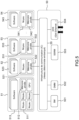
- FIG. 4 presents the architecture of the Figure 3b in more detail.
- functions dependent on the signals from the sensors/actuators connected to these modules are specified as an example for each module 33. It also specifies the signal aggregation and command distribution modules 33, each with the sensors or actuators 1" that they control.
- the various functions of the vehicle are implemented via all of these sensors and actuators. More precisely, the sensors and actuators participate in the execution of the functions, the calculation being carried out on the PCU 31, and possibly on one or more secondary computers 32.
- PIUs Physical Interface Units
- All these PIUs are interconnected using the real-time network, which in particular allows for controlling the latencies in the transmission of the synchronization signals for the entire system, and above all allows for controlling the latencies in the transmission of packets containing sensor data and actuator data/commands.
- the network may be composed of switches 34 and portals or gateways allowing the routing of network data packets and securing the connection between the system architecture and the outside world (multimedia connectivity, for example).
- the PCU assigned to the multimedia domain accesses the network via a gateway 35, the latter being interfaced to the network via a PIU.
- This architecture can therefore execute high-criticality functions, such as powertrain control, battery monitoring, or the ADAS safety system. It can simultaneously execute the control of low-critical functions such as air conditioning, as well as other types of services. All these functions can be executed by a single PCU 31 thanks to computing resource pooling technologies such as hypervisors, for example.
- a PCU is a modular, low-power system composed of a motherboard 50 and one or more computing subsystems 51, 52, 53, 54.
- the subsystems may be completely heterogeneous between them, i.e. they may comprise processors 511, 521, 531, 541 of different types and/or different specificities.
- These subsystems may be integrated into the motherboard or available (integrated) in the form of daughter cards as illustrated in the example of the Figure 5 In this example, four daughter cards 51, 52, 53, 54 are connected to the motherboard 50.
- the subsystems communicate with the motherboard and the rest of the system using a deterministic communication infrastructure 55 integrated on the motherboard.
- the computing resources of the subsystems are composed for each of one or more processors 511, 521, 531, 541 coupled to a private memory 512, 522, 532, 542 capable of executing one or more software partitions 513, 523, 533, 543.
- these software partitions can be applications, processes (whose segregation is achieved by operating system software mechanisms), or even complete operating systems, separated with the help of hypervisor mechanisms.
- the PCU also includes functional blocks to support the execution of additional functions to guarantee or improve the properties of the architecture.
- Services such as application segregation or data protection, are used to support the execution of software partitions on each computing resource; a hypervisor can be used, for example.
- a “Data Management Module” (DMM) functional block 502 provides the various components of the vehicle with unified access to data related to the sensors and actuators distributed throughout the vehicle as well as to data generated by the subsystems.
- This functional block 502 can, for example, be implemented via a virtually shared distributed memory service (a DSM - Distributed Shared Memory) used to simplify communications between the subsystems and store and manage all of the vehicle data to facilitate access.
- This service can be implemented via a service of a hypervisor or an operating system, for example.
- This distributed service can be supported by a data management hardware component allowing deterministic access to the sensors and actuators via the PIUs and to the data generated by the computing subsystems 51, 52, 53, 54.
- the DMM functional block 502 has the particular advantage of providing a time guarantee for access to the data distributed throughout the vehicle.
- the significant pooling permitted by the architecture according to the invention can be based in particular advantageously on this functional block 502. It provides a unified view of the different memories belonging to resources distributed at the level of the sensors and actuators.
- the functional block 502 relies for example on a hardware accelerator to maintain data consistency within the system, for example by pre-loading sensor data at regular intervals autonomously. All communications with sensors and actuators, via the PIUs, pass through virtual memory, which makes it possible to present the distributed memories in the system (memories of sensors, actuators, PIUs, PCUs, etc.) as a single shared memory machine. This gives a unified view of the memories, accessible to all computers.
- An advantage of this solution is that if attributes are added to the data, an efficient and centralized access control system makes it possible to strongly secure the vehicle data and to reinforce the concept of global virtual domains presented below.
- a “Synchronization Manager” (SM) functional block 501 ensures synchronization between the computing subsystems, possibly distributed throughout the vehicle.
- This functional block 501 can be implemented, for example, by a hardware accelerator called HSM (Hardware Synchronization Manager).
- HSM Hardware Synchronization Manager
- the DMM and SM functional blocks can be coupled (or even, for example, implemented in the same functional block) in order to perform, for example, data-related synchronizations.
- a functional block 503 called “Safety and Reliability Support Module” (SSRM) ensures and supports services related to the safety of the system operation and its reliability, for example by managing redundancies in the system.
- This functional block can be implemented, for example, by distributed software services, possibly supported by hardware accelerators or specialized interfaces for duplication.
- This motherboard-daughter card architecture is advantageously flexible and composable. It constitutes a generic system that can target different vehicle ranges by ensuring current and future functions, such as autonomous driving applications or complex infotainment applications for example. An important point lies in the possibility of reusing the various components of the system in the greatest number of vehicles in order to reduce production costs.
- daughter cards allows to use the appropriate resources in relation to the properties of the functions to be executed, for example functions using screens or image processing can be grouped on cards with an SoC equipped with a GPU (Graphics Processing Unit or Graphics Processor) while highly critical functions can be sent to a daughter card with reinforced time control.
- SoC SoC equipped with a GPU (Graphics Processing Unit or Graphics Processor)
- highly critical functions can be sent to a daughter card with reinforced time control.
- the architecture advantageously allows to optimize the calculation system by grouping functions having the same properties on a calculation subsystem optimized to ensure these properties (types of calculation, security/safety, time criticality, etc.).
- the system's architecture itself can be optimized by dividing and/or separating functions, and grouping them according to their properties on suitable and possibly highly heterogeneous hardware resources (subsystems) (with the inclusion of dedicated accelerators, for example).
- subsystems hardware resources
- accelerators dedicated accelerators
- daughter cards connected to a motherboard allows the use of high bandwidth and low latency interfaces, depending on needs, for raw image acquisition for example.
- the motherboard has a network backbone function allowing the daughter cards to be interconnected with each other as well as with the rest of the system, this interface with the rest of the system being carried out by duplicated links (or in any case redundant, and not necessarily homogeneous), for example gigabit Ethernet 504 links.
- This motherboard also contains functions observing the integrity of the system. Specific functions can be added such as access arbitration, protection or management of complexity, heterogeneity or non-functional parameters such as temperature, component aging or even energy consumption.
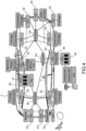
- FIG. 6 illustrates a representation of an architecture according to the invention with a PCU 31, composed of a motherboard 50 and daughter cards 51, 52, 53, 54 communicating with PIUs 33, geographically distributed in the system to be controlled, via a network 36 implemented by an Ethernet type network.
- the PIUs aggregate the signals from the sensors of the different geographical domains 61, 62, 63, 64, 65 and send commands to these same domains. These domains can for example correspond to the front left, the front right, the rear left, the rear right or the passenger compartment of the vehicle. More precisely in the case of the Figure 6 , each PIU is assigned to several functional areas (braking, powertrain, driving assistance, etc.) by addressing several sensors and/or actuators linked to its geographical area. In other words, PIUs do not have a priority assignment by functional area, but a geographical assignment. There may exist, for certain systems, special cases of implementation where the assignment by geographical areas corresponds to the assignment by functional areas.
- the PIUs only have the function of aggregating the sensor data and redistributing the commands, they do not carry out high-level processing in the sense that this processing does not involve autonomous decision-making, the controls and decision-making always being taken at the level of the central computer 31 or possibly of the secondary computer(s) 32.
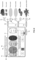
- FIG. 7 illustrates an example of the implementation of a PIU.
- the PIU is a network component used to connect sensors and actuators to the rest of the electronic architecture but also to gateways 35 and other network elements.
- the PIU represented addresses three functional areas by the sensors and actuators to which it is connected: the motorization 75, the lighting 76 and the braking 77.
- This PIU can for example be placed at the front left of a vehicle and thus be connected to the sensors and actuators placed in an area of the front left.
- the architecture of the PIU of the Figure 7 is generic, in particular it does not depend on the functional areas addressed, only the sizing (computing system, memory) or the interfaces can be dependent. This makes it possible in particular to reduce the difficulty of integration and also production costs. More particularly, the Figure 7 presents the general structure of a PIU.
- the PIU's function is, among other things, to packetize signals from sensors in order to transmit them to the PCU (or to several PCUs) and to distribute commands to actuators by processing packets from the PCU.
- the PIU is responsible for presenting to the network 36, and in particular to the PCU, a unified view of the signals to the actuators (and possibly to the sensors) and coming from the sensors (and possibly coming from the actuators) which may in practice be highly heterogeneous, in particular by carrying out translations of communication protocols.
- the interfaces 71 with the sensors and actuators managed by the PIU may therefore be of different types such as for example FlexRay, CAN, PWM switch, SPI, QSPI or ADC.
- the unified view of the sensors and actuators by the PCU translates in practice into a single protocol for communicating data from or to a PIU (seen from the PCU side), regardless of the communication interface with a sensor and/or an actuator.
- the PIU is thus able to communicate with these different standards to format the data received from the sensors/actuators into real-time Ethernet packets transmitted over the network 36 and conversely send commands in the different standards, commands coming from the PCU in the form of Ethernet packets.
- a protocol other than Ethernet can of course be used.
- the real-time interconnection network 36 has a greater bandwidth than the interfaces between the PIUs and the sensors/actuators. This therefore makes it possible to reduce the number of cables in the vehicle by sharing this interconnection link.
- the PIU takes heterogeneous signals coming from the sensors by ensuring the temporal compatibility of their sending with the operation of the vehicle (by a pre-established and modifiable configuration for example) and fills each transmitted packet to the maximum in order in particular to maximize the bandwidth and minimize the latency, by grouping digital data of different signals in the same packet.
- the packets coming from the computers aggregate a maximum of digitized command data intended for the actuators addressed by the PIU, the PIU being responsible for redistributing these commands while ensuring the temporal compatibility of their transmission with the operation of the vehicle (by a pre-established and modifiable configuration for example), thus ensuring temporal control.
- actuators and sensors not shown are associated with each of these components. They are controlled by actuators, themselves controlled by the control data from the PCU transmitted via the communication network 36, the communication processor 72 and the communication interfaces 71. Similarly, sensors (cameras, speed sensors, temperature sensors, etc.) transmit data to the PCU via the reverse path.
- the PIU is also in charge of various services such as safety, security (e.g. data encryption/decryption), message integrity control and/or message redundancy management. Packet processing, protocol translations and security and control functions are performed by a communication processor 72.
- a power supply unit 73 is also provided. It may or may not be integrated into the PIU.
- the overall power supply of the system can thus be distributed in the image of the geographical distribution of the PIUs and the PCU(s).
- the complete architecture is advantageous from this point of view. Indeed, the electrical tree can have its own topology (or follow the interconnections of the communication network), but the control is advantageously transmitted by the computer control network of the system.
- a PIU can be powered only when needed, the command to start the power supply unit 73 as well as the power supplies of the sensors/actuators connected to the PIUs can be transmitted by a control signal passing through the network 34, 36, 74.
- a suitable interface is integrated into the power supply unit, for example a smart MOS transistor or a smart switch. Thanks to the PCU's overall view of the architecture and the ability to transmit fine-grained control signals over the interconnection network, very fine-grained management of power supplies is possible.
- Ethernet link 74 for example, to carry out communications makes it possible to obtain the necessary bandwidth.
- This link also provides flexibility and allows the use of different communication standards. Time management, guaranteeing control of information propagation times, can be based on standards supporting the transport of information of different criticality.
- a notable advantage of the electronic system according to the invention is its ability to advantageously support a network allowing the segregation of communications, for example via the use of virtual links (VLAN type, etc.) and therefore virtual private networks in order to create virtual domains on demand and, for example, separate critical domains from non-critical domains, without however physically allocating a part of the architecture to a particular domain, as in the case of architectures based on functional domains.
- VLAN type, etc. virtual private networks
- FIG 8 shows how the use of virtual domains allows physically distributed sensors and actuators to be logically grouped and separated into various independent virtual zones. More precisely, the figure 8 illustrates virtual domains 81, 82, 83, 84, 85 implemented through the use of virtual links between different components and parts/subassemblies of the system. These virtual domains are for example a combination of segregation technologies of which a virtual local area network (VLAN) is part.
- a virtual domain 84 covers several processors (CPUs) and a partition of processing of the PCU 31 (forming a virtual machine), as well as the aggregation and control interfaces of a group of sensors and actuators 80 which can be distributed or distributed in the vehicle. This can be the virtual domain which makes it possible to manage the engine domain with its sensors and actuators distributed in the vehicle, and the corresponding virtual machine 800.
- VLAN virtual local area network
- virtual domains can be created using a combination of techniques, in particular by means of data attributes placed by the PIUs 33, virtual links on the interconnection network 36, attribute management in the DMM 502, or even hardware (one processor per domain for example) and software segregation techniques, with in this case one processor for several domains, the segregation being achieved by memory protection obtained by the basic functions of an operating system or even by a hypervisor, which makes it possible to separate two operating systems running on the same hardware resource.
- this consists in particular of separating groups of data from different sensors or actuators on a PIU by assigning a different attribute to each group.
- the switches used to interconnect the components are designed to support good system properties such as bandwidth, low latency, security and safety.
- the gateway block 35 provides security by isolating the architecture from external communications handled by a second PCU 32.
- FIG 9 illustrates the virtual domains previously described in an architecture according to the invention, by reflecting the different hardware and software contributors.
- the invention advantageously creates domains virtual domains to separate the constraints related to the physical loading of the system components from the constraints of data usage and allocation of vehicle functions on the computing cores.
- These virtual domains can be efficiently created using the properties of the architecture: logical/virtual domains can for example be created (even dynamically) using the association between the virtual links provided by the interconnection 34, 36, the DMM data management functional block 502, the security attributes on the data managed by this DMM functional block 502 and the use of software and/or hardware segregation services between applications/functions such as hypervision or operating system technologies.
- These domains can also be supported by sensor/actuator or subsystem authentication technologies, for example implemented via authentication services.
- the PCU 31 computers communicate with the PIUs 33 distributed in the vehicle, via the communications network.
- Switches 34 supporting virtual links are distributed to direct communications to the PIUs.
- the figure 9 illustrates the physical part/logical part dichotomy well.
- the rear and front headlights, physically distant, are in the same virtual domain (and potentially synchronized) although they are connected to different PIUs. The same is true for the front and rear brakes.
- the use of such a subsystem is carried out in the case where the flow rate required by the data transmission is greater than the maximum admissible flow rate on the interconnection network 36.
- the use of this subsystem can also be advantageous in the case where the latency of the interconnection network 36 is too high compared to the admissible latency for the application.
- connection between the PCU 31 and this subsystem 101 may be preferred: for example, a high-speed input/output block 102 may be used to connect the subsystem 101 to the PCU 31.
- This block makes it possible to position the subsystem 101 as a daughter card of the PCU or to connect it to the PCU by a high-speed serial cable link if it is remote in the vehicle.
- This makes it possible to maintain the modularity properties of the architecture and the possibility of adapting the subsystem to the types of sensors or actuators, even during operation of the vehicle (for example during an update of the sensors in a second assembly).
- the link between the subsystem 101 and the PCU 31 is, for example, a high-speed link using a protocol passing through an automotive-certified connector as part of a motherboard-daughterboard link, unlike the PIUs which are, for example, on an Ethernet or other type link.
- both types of link arrive on the communication infrastructure 55 of the PCU motherboard, which is a deterministic communication network, the entire architecture making it possible to maintain the synchronization properties between the different elements.
Landscapes
- Engineering & Computer Science (AREA)
- Computer Networks & Wireless Communication (AREA)
- Signal Processing (AREA)
- Health & Medical Sciences (AREA)
- Computing Systems (AREA)
- General Health & Medical Sciences (AREA)
- Medical Informatics (AREA)
- Small-Scale Networks (AREA)
- Control By Computers (AREA)
Claims (18)
- Elektronische Architektur, die in einem System mitgeführt wird, das die Verwaltung der Funktionen des Systems gewährleistet, wobei die Funktionen über einen Satz von Sensoren und Betätigungselementen implementiert werden, dadurch gekennzeichnet, dass sie mindestens Folgendes umfasst:- einen zentralen Rechner (31);- ein Echtzeit-Kommunikationsnetzwerk (34, 36);- einen Satz von Schnittstellenmodulen (33), die jeweils einem geographischen Gebiet des Systems zugewiesen sind, wobei jedes Modul:o Signale von mindestens einem der Sensoren des ihm zugewiesenen Gebiets aggregiert und diese Signale über das Kommunikationsnetzwerk an den zentralen Rechner sendet;o und/oder Steuersignale an mindestens eines der Betätigungselemente des ihm zugewiesenen Gebiets verteilt;wobei der zentrale Rechner die Betätigungselemente entsprechend den von den Sensoren stammenden Signalen steuert, wobei die Steuersignale der Betätigungselemente über das Kommunikationsnetzwerk an die Schnittstellenmodule (33) gesendet werden, wobei mindestens eines der Schnittstellenmodule (33) die von Sensoren mehrerer Funktionsbereiche ausgegebenen Signale aggregiert und Befehle an Betätigungselemente mehrerer Funktionsbereiche verteilt, wobei sich die Sensoren und Betätigungselemente in dem geografischen Gebiet befinden, das dem mindestens einen Modul (33) zugewiesen ist.
- Architektur nach Anspruch 1, dadurch gekennzeichnet, dass mindestens eines der Schnittstellenmodule auch Signale von mindestens einem der Betätigungselemente aggregiert und/oder Signale an mindestens einen der Sensoren verteilt.
- Architektur nach einem der vorhergehenden Ansprüche, dadurch gekennzeichnet, dass der zentrale Rechner (31, 32) aus einer Hauptplatine (50) und Rechensubsystemen (51, 52, 53, 54, 55) besteht, wobei jedes Subsystem einen oder mehrere Prozessoren (511, 521, 531, 541) umfasst, die mit einem privaten Speicher (512, 522, 532, 542) gekoppelt sind und in der Lage sind, mehrere Software-Partitionen (513, 523, 533, 534) auszuführen, wobei die Subsysteme untereinander und mit dem Kommunikationsnetzwerk (34, 36) mittels einer auf der Hauptplatine implementierten Verbindungsinfrastruktur (55) kommunizieren.
- Architektur nach Anspruch 3, dadurch gekennzeichnet, dass sie einen zentralisierten Datenverwaltungsfunktionsblock (502) umfasst, der es ermöglicht, auf die Daten der im Rechner (31, 32) und in den Modulen (33) vorhandenen Speicher zuzugreifen, wobei der Funktionsblock (502) den verschiedenen Komponenten der Architektur einen einheitlichen Zugriff auf die mit den im System verteilten Sensoren und Betätigungselementen verbundenen Daten sowie auf die von den Rechensubsystemen erzeugten Daten gewährleistet.
- Architektur nach Anspruch 4, dadurch gekennzeichnet, dass der Funktionsblock (502) mittels eines verteilten Speicherdiensts realisiert wird, der virtuell zwischen dem Rechner (31, 32) und den Modulen (33) geteilt wird, sodass die gesamte Kommunikation des zentralen Rechners (31, 32) mit den Sensoren und Betätigungselementen über den virtuellen Speicher erfolgt und sodass die in der Architektur verteilten Speicher und alle Sensoren und Betätigungselemente sich dem zentralen Rechner wie ein einziger gemeinsam genutzter Speicher darstellen.
- Architektur nach Anspruch 5, dadurch gekennzeichnet, dass der Funktionsblock (502) den Zugriff auf die Daten durch die Verwendung von mit den Daten verknüpften Attributen ermöglicht.
- Architektur nach einem der Ansprüche 3 bis 6, dadurch gekennzeichnet, dass sie einen Funktionsblock (501) zum Gewährleisten der Synchronisation zwischen den Rechensubsystemen umfasst.
- Architektur nach einem der Ansprüche 3 bis 7, dadurch gekennzeichnet, dass sie einen Funktionsblock (503) zum Gewährleisten und Unterstützen der mit der Betriebssicherheit des Systems verbundenen Dienste umfasst.
- Architektur nach einem der vorhergehenden Ansprüche, dadurch gekennzeichnet, dass ein Schnittstellenmodul (33) mindestens Folgendes umfasst:- einen Kommunikationsprozessor (72);- Kommunikationsschnittstellen (71) zwischen dem Prozessor (72) und Betätigungselementen und/oder Sensoren;- eine Kommunikationsschnittstelle (74) zwischen dem Prozessor und dem Kommunikationsnetzwerk (34, 36);wobei der Kommunikationsprozessor die Funktion aufweist, die von den Sensoren stammenden Daten in Paketen anzuordnen, um sie über das Kommunikationsnetzwerk an den zentralen Rechner (31, 32) zu übertragen, und die von dem zentralen Rechner stammenden Steuerdaten über das Kommunikationsnetzwerk an die Betätigungselemente zu verteilen.
- Architektur nach Anspruch 9, dadurch gekennzeichnet, dass die Kommunikationsschnittstellen (71) zwischen dem Prozessor und den Betätigungselementen und/oder Sensoren unterschiedlicher Art sind, wobei der Prozessor (72) Übersetzungen von Kommunikationsprotokollen der Schnittstellen durchführt, um die Daten mit dem zentralen Rechner gemäß einem einzigen Protokoll auszutauschen.
- Architektur nach einem der vorhergehenden Ansprüche, dadurch gekennzeichnet, dass sie mindestens ein Gateway (35) umfasst, das in der Lage ist, das Kommunikationsnetzwerk (34, 36) mit mindestens einem anderen Kommunikationsnetzwerk zu verbinden.
- Architektur nach Anspruch 11, dadurch gekennzeichnet, dass sie einen sekundären Rechner (32) umfasst, der mit dem Kommunikationsnetzwerk (34, 36) mittels des Gateways (35) kommuniziert, wobei der sekundäre Rechner (32) mit dem anderen Netzwerk verbundene Funktionen steuert.
- Architektur nach einem der Ansprüche 3 bis 12, dadurch gekennzeichnet, dass sie eine Kombination von Techniken in Ergänzung der Ausführung mehrerer Software-Partitionen umfasst, wobei die Kombination virtuelle Domänen (81, 82, 83, 84, 85, 91, 92, 93, 94) bildet, wobei jede virtuelle Domäne mindestens eine der Partitionen abdeckt, welche die Schnittstellenmodule (33) einer Gruppe von Sensoren und Betätigungselementen verarbeitet.
- Architektur nach Anspruch 13, dadurch gekennzeichnet, dass die Kombination eine Kombination von Mechanismen zur Segregation der Datenübertragung in dem Echtzeit-Kommunikationsnetzwerk (34, 36) umfasst.
- Architektur nach einem der Ansprüche 13 oder 14, dadurch gekennzeichnet, dass die Kombination auf Datenattributen basiert, die von den Schnittstellenmodulen (33) platziert werden.
- Architektur nach einem der Ansprüche 13 bis 15, dadurch gekennzeichnet, dass die Kommunikationen zwischen dem zentralen Rechner (31) und den Schnittstellenmodulen (33) von dem Rechner (31) gesteuert werden.
- Architektur nach einem der Ansprüche 3 bis 14, dadurch gekennzeichnet, dass sie ein Subsystem (101) zur Verwaltung der Eingangs- und Ausgangssignale mit hoher Übertragungsgeschwindigkeit umfasst, das mit der Verbindungsinfrastruktur (55) der Hauptplatine verbunden ist, wobei das Subsystem aus einer oder mehreren Tochterkarten besteht und die Funktion eines Schnittstellenmoduls (33) zwischen Sensoren und/oder Betätigungselementen mit hoher Übertragungsgeschwindigkeit und dem zentralen Rechner (31) gewährleistet.
- Architektur nach einem der vorhergehenden Ansprüche, dadurch gekennzeichnet, dass das Kommunikationsnetzwerk ein Netzwerk vom deterministischen Ethernet-Typ ist.
Applications Claiming Priority (2)
| Application Number | Priority Date | Filing Date | Title |
|---|---|---|---|
| FR1873551A FR3090530B1 (fr) | 2018-12-20 | 2018-12-20 | Architecture électronique pour système embarqué |
| PCT/EP2019/084264 WO2020126624A1 (fr) | 2018-12-20 | 2019-12-09 | Architecture electronique pour systeme embarque |
Publications (2)
| Publication Number | Publication Date |
|---|---|
| EP3898341A1 EP3898341A1 (de) | 2021-10-27 |
| EP3898341B1 true EP3898341B1 (de) | 2025-06-04 |
Family
ID=66676717
Family Applications (1)
| Application Number | Title | Priority Date | Filing Date |
|---|---|---|---|
| EP19813369.6A Active EP3898341B1 (de) | 2018-12-20 | 2019-12-09 | Elektronische architektur für ein bordsystem |
Country Status (5)
| Country | Link |
|---|---|
| US (1) | US12160325B2 (de) |
| EP (1) | EP3898341B1 (de) |
| JP (1) | JP7482135B2 (de) |
| FR (1) | FR3090530B1 (de) |
| WO (1) | WO2020126624A1 (de) |
Families Citing this family (8)
| Publication number | Priority date | Publication date | Assignee | Title |
|---|---|---|---|---|
| CN112035384A (zh) * | 2020-08-28 | 2020-12-04 | 西安微电子技术研究所 | 一种星载信息处理系统、方法、设备及可读存储介质 |
| CN113401077B (zh) * | 2021-08-19 | 2021-11-16 | 北京理工大学深圳汽车研究院(电动车辆国家工程实验室深圳研究院) | 智能车辆动态可重构网络系统及网络调度方法 |
| EP4297347A1 (de) * | 2022-06-21 | 2023-12-27 | Siemens Aktiengesellschaft | System, das einen kommunikationsbus zur datenübertragung einschliesst, und verfahren zum betrieb eines kommunikationsbusses |
| IT202200023982A1 (it) * | 2022-11-22 | 2024-05-22 | St Microelectronics Alps Sas | Rete di comunicazione di veicolo |
| US20240317161A1 (en) * | 2023-03-24 | 2024-09-26 | Ford Global Technologies, Llc | Distributed automotive electronic control units with wired control circuitry |
| CN117445839B (zh) * | 2023-11-09 | 2024-05-03 | 南京顺恒环保科技发展有限公司 | 一种环保车辆智能化控制系统及使用方法 |
| KR20250100185A (ko) * | 2023-12-26 | 2025-07-03 | 삼성전자주식회사 | 스토리지 장치, 스토리지 장치를 포함하는 전자 장치, 및 스토리지 장치의 구동 방법 |
| CN118843236B (zh) * | 2024-09-20 | 2024-11-26 | 奥特酷智能科技(南京)有限公司 | 一种基于时间戳的域控制器灯光同步系统及方法 |
Family Cites Families (16)
| Publication number | Priority date | Publication date | Assignee | Title |
|---|---|---|---|---|
| US6882917B2 (en) * | 1999-07-30 | 2005-04-19 | Oshkosh Truck Corporation | Steering control system and method |
| US6708239B1 (en) * | 2000-12-08 | 2004-03-16 | The Boeing Company | Network device interface for digitally interfacing data channels to a controller via a network |
| DE10248843B4 (de) | 2002-10-19 | 2005-01-20 | Daimlerchrysler Ag | Vorrichtung zum Steuern eines Motors oder Getriebes |
| DE10354602A1 (de) * | 2003-11-21 | 2005-06-16 | Robert Bosch Gmbh | Verbindungselemente, Verfahren zur Buskommunikation zwischen einem Steuergerät zur Ansteuerung von Personenschutzmitteln als Master und wenigstens einem Verbindungselement zur Gewichtsmessung in einem Sitz als Slave und Bus-System |
| JP4478037B2 (ja) | 2004-01-30 | 2010-06-09 | 日立オートモティブシステムズ株式会社 | 車両制御装置 |
| US20070113070A1 (en) * | 2005-11-04 | 2007-05-17 | Lackritz Neal M | Secure active suspension system |
| FR2943037B1 (fr) * | 2009-03-11 | 2012-09-21 | Airbus France | Systeme de commande d'aeronef a architecture modulaire integre. |
| DE102012209108B4 (de) | 2012-05-30 | 2014-05-15 | Siemens Aktiengesellschaft | Netzwerkeinrichtung, Netzwerkanordnung und Verfahren zum Betreiben einer Netzwerkanordnung |
| DE102012215765A1 (de) * | 2012-09-05 | 2014-05-15 | Robert Bosch Gmbh | Gateway-Modul für ein Kommunikationssystem, Kommunikationssystem und Verfahren zur Übertragung von Daten zwischen Teilnehmern eines Kommunikationssystems |
| US20140107932A1 (en) * | 2012-10-11 | 2014-04-17 | Aliphcom | Platform for providing wellness assessments and recommendations using sensor data |
| US9694765B2 (en) * | 2015-04-20 | 2017-07-04 | Hitachi, Ltd. | Control system for an automotive vehicle |
| US10178206B2 (en) * | 2015-11-10 | 2019-01-08 | Microsoft Technology Licensing, Llc | Multi-protocol gateway for connecting sensor devices to cloud |
| US11072356B2 (en) | 2016-06-30 | 2021-07-27 | Transportation Ip Holdings, Llc | Vehicle control system |
| US10055904B2 (en) * | 2016-06-23 | 2018-08-21 | Ford Global Technologies, Llc | Vehicle gateway network protection |
| US10332320B2 (en) | 2017-04-17 | 2019-06-25 | Intel Corporation | Autonomous vehicle advanced sensing and response |
| GB2568236B (en) * | 2017-10-31 | 2020-11-04 | Jaguar Land Rover Ltd | Improved vehicle data communications network |
-
2018
- 2018-12-20 FR FR1873551A patent/FR3090530B1/fr active Active
-
2019
- 2019-12-09 JP JP2021536065A patent/JP7482135B2/ja active Active
- 2019-12-09 US US17/416,341 patent/US12160325B2/en active Active
- 2019-12-09 EP EP19813369.6A patent/EP3898341B1/de active Active
- 2019-12-09 WO PCT/EP2019/084264 patent/WO2020126624A1/fr not_active Ceased
Also Published As
| Publication number | Publication date |
|---|---|
| WO2020126624A1 (fr) | 2020-06-25 |
| US20220086021A1 (en) | 2022-03-17 |
| JP2022514688A (ja) | 2022-02-14 |
| FR3090530A1 (fr) | 2020-06-26 |
| EP3898341A1 (de) | 2021-10-27 |
| FR3090530B1 (fr) | 2021-04-23 |
| JP7482135B2 (ja) | 2024-05-13 |
| US12160325B2 (en) | 2024-12-03 |
Similar Documents
| Publication | Publication Date | Title |
|---|---|---|
| EP3898341B1 (de) | Elektronische architektur für ein bordsystem | |
| Zhu et al. | Requirements-driven automotive electrical/electronic architecture: A survey and prospective trends | |
| US10315520B2 (en) | Apparatuses and methods of an in-vehicle gateway system for monitoring and controling in-vehicle subsystems | |
| CN109474912B (zh) | 一种车载网关系统以及车载子系统的监控方法和装置 | |
| JP2020037387A (ja) | 自動車アプリケーションのための電力およびデータセンタ(PDC:power and data center) | |
| CN114500144A (zh) | 通用软件通信总线 | |
| CN106230678A (zh) | 基于车载网关控制器的信息处理方法及网关控制器 | |
| CN112572329B (zh) | 一种汽车网络控制系统 | |
| FR3032078A1 (fr) | Architecture hybride de transmission d'informations avioniques et systeme correspondant | |
| WO2021020211A1 (ja) | 車両制御システム | |
| US20200007663A1 (en) | Method and device for inter-process communication in network | |
| EP4205362A1 (de) | Netzwerk mit priorisierten datenströmen, das an bord eines fahrzeugs installiert ist | |
| JP7839284B2 (ja) | スリープ/ウェイクアップ方法、システム、および装置 | |
| WO2021020221A1 (ja) | 車両制御システム | |
| US20250077222A1 (en) | Vehicle control method and apparatus, and vehicle | |
| EP3039827B1 (de) | Verfahren und vorrichtung zur steuerung der übertragung von reaktionsrahmen aus slave-vorrichtungen in einem lin-netzwerk gegenüber einer anderen art von netzwerk | |
| Velusamy et al. | Automotive sensor infrastructure-challenges and opportunities | |
| EP3114817A1 (de) | Verfahren und system zum herunterladen von daten auf mindestens einen computer | |
| CN119213409A (zh) | 一种协同控车方法及相关装置 | |
| EP4607366A1 (de) | Verfahren und system zur stratifizierung von datenpipelines für zugang mit niedriger latenz | |
| WO2026046567A1 (fr) | Passerelle multi-protocole | |
| CA3261015A1 (en) | Method and system for data pipeline stratification for low latency access | |
| FR3084032A1 (fr) | Systeme de capteurs mutualises pour vehicule. | |
| CN118790178A (zh) | 一种车辆控制器系统及车辆 | |
| CN121691608A (zh) | 数据传输方法、车载以太网系统、计算机设备及存储介质 |
Legal Events
| Date | Code | Title | Description |
|---|---|---|---|
| STAA | Information on the status of an ep patent application or granted ep patent |
Free format text: STATUS: UNKNOWN |
|
| STAA | Information on the status of an ep patent application or granted ep patent |
Free format text: STATUS: THE INTERNATIONAL PUBLICATION HAS BEEN MADE |
|
| PUAI | Public reference made under article 153(3) epc to a published international application that has entered the european phase |
Free format text: ORIGINAL CODE: 0009012 |
|
| STAA | Information on the status of an ep patent application or granted ep patent |
Free format text: STATUS: REQUEST FOR EXAMINATION WAS MADE |
|
| 17P | Request for examination filed |
Effective date: 20210622 |
|
| AK | Designated contracting states |
Kind code of ref document: A1 Designated state(s): AL AT BE BG CH CY CZ DE DK EE ES FI FR GB GR HR HU IE IS IT LI LT LU LV MC MK MT NL NO PL PT RO RS SE SI SK SM TR |
|
| RAP3 | Party data changed (applicant data changed or rights of an application transferred) |
Owner name: RENAULT S.A.S Owner name: COMMISSARIAT A L'ENERGIE ATOMIQUE ET AUX ENERGIES ALTERNATIVES |
|
| DAV | Request for validation of the european patent (deleted) | ||
| DAX | Request for extension of the european patent (deleted) | ||
| RAP3 | Party data changed (applicant data changed or rights of an application transferred) |
Owner name: RENAULT S.A.S Owner name: COMMISSARIAT A L'ENERGIE ATOMIQUE ET AUX ENERGIES ALTERNATIVES |
|
| P01 | Opt-out of the competence of the unified patent court (upc) registered |
Effective date: 20230530 |
|
| STAA | Information on the status of an ep patent application or granted ep patent |
Free format text: STATUS: EXAMINATION IS IN PROGRESS |
|
| 17Q | First examination report despatched |
Effective date: 20240102 |
|
| RAP3 | Party data changed (applicant data changed or rights of an application transferred) |
Owner name: RENAULT S.A.S Owner name: COMMISSARIAT A L'ENERGIE ATOMIQUE ET AUX ENERGIESALTERNATIVES |
|
| GRAP | Despatch of communication of intention to grant a patent |
Free format text: ORIGINAL CODE: EPIDOSNIGR1 |
|
| STAA | Information on the status of an ep patent application or granted ep patent |
Free format text: STATUS: GRANT OF PATENT IS INTENDED |
|
| INTG | Intention to grant announced |
Effective date: 20250103 |
|
| GRAS | Grant fee paid |
Free format text: ORIGINAL CODE: EPIDOSNIGR3 |
|
| GRAA | (expected) grant |
Free format text: ORIGINAL CODE: 0009210 |
|
| STAA | Information on the status of an ep patent application or granted ep patent |
Free format text: STATUS: THE PATENT HAS BEEN GRANTED |
|
| AK | Designated contracting states |
Kind code of ref document: B1 Designated state(s): AL AT BE BG CH CY CZ DE DK EE ES FI FR GB GR HR HU IE IS IT LI LT LU LV MC MK MT NL NO PL PT RO RS SE SI SK SM TR |
|
| REG | Reference to a national code |
Ref country code: GB Ref legal event code: FG4D Free format text: NOT ENGLISH |
|
| REG | Reference to a national code |
Ref country code: CH Ref legal event code: EP |
|
| REG | Reference to a national code |
Ref country code: DE Ref legal event code: R096 Ref document number: 602019070821 Country of ref document: DE |
|
| REG | Reference to a national code |
Ref country code: IE Ref legal event code: FG4D Free format text: LANGUAGE OF EP DOCUMENT: FRENCH |
|
| REG | Reference to a national code |
Ref country code: NL Ref legal event code: MP Effective date: 20250604 |
|
| PG25 | Lapsed in a contracting state [announced via postgrant information from national office to epo] |
Ref country code: ES Free format text: LAPSE BECAUSE OF FAILURE TO SUBMIT A TRANSLATION OF THE DESCRIPTION OR TO PAY THE FEE WITHIN THE PRESCRIBED TIME-LIMIT Effective date: 20250604 Ref country code: FI Free format text: LAPSE BECAUSE OF FAILURE TO SUBMIT A TRANSLATION OF THE DESCRIPTION OR TO PAY THE FEE WITHIN THE PRESCRIBED TIME-LIMIT Effective date: 20250604 |
|
| REG | Reference to a national code |
Ref country code: LT Ref legal event code: MG9D |
|
| PG25 | Lapsed in a contracting state [announced via postgrant information from national office to epo] |
Ref country code: NO Free format text: LAPSE BECAUSE OF FAILURE TO SUBMIT A TRANSLATION OF THE DESCRIPTION OR TO PAY THE FEE WITHIN THE PRESCRIBED TIME-LIMIT Effective date: 20250904 Ref country code: GR Free format text: LAPSE BECAUSE OF FAILURE TO SUBMIT A TRANSLATION OF THE DESCRIPTION OR TO PAY THE FEE WITHIN THE PRESCRIBED TIME-LIMIT Effective date: 20250905 |
|
| PG25 | Lapsed in a contracting state [announced via postgrant information from national office to epo] |
Ref country code: PL Free format text: LAPSE BECAUSE OF FAILURE TO SUBMIT A TRANSLATION OF THE DESCRIPTION OR TO PAY THE FEE WITHIN THE PRESCRIBED TIME-LIMIT Effective date: 20250604 |
|
| PG25 | Lapsed in a contracting state [announced via postgrant information from national office to epo] |
Ref country code: BG Free format text: LAPSE BECAUSE OF FAILURE TO SUBMIT A TRANSLATION OF THE DESCRIPTION OR TO PAY THE FEE WITHIN THE PRESCRIBED TIME-LIMIT Effective date: 20250604 |
|
| PG25 | Lapsed in a contracting state [announced via postgrant information from national office to epo] |
Ref country code: HR Free format text: LAPSE BECAUSE OF FAILURE TO SUBMIT A TRANSLATION OF THE DESCRIPTION OR TO PAY THE FEE WITHIN THE PRESCRIBED TIME-LIMIT Effective date: 20250604 |
|
| PG25 | Lapsed in a contracting state [announced via postgrant information from national office to epo] |
Ref country code: RS Free format text: LAPSE BECAUSE OF FAILURE TO SUBMIT A TRANSLATION OF THE DESCRIPTION OR TO PAY THE FEE WITHIN THE PRESCRIBED TIME-LIMIT Effective date: 20250904 |
|
| PG25 | Lapsed in a contracting state [announced via postgrant information from national office to epo] |
Ref country code: LV Free format text: LAPSE BECAUSE OF FAILURE TO SUBMIT A TRANSLATION OF THE DESCRIPTION OR TO PAY THE FEE WITHIN THE PRESCRIBED TIME-LIMIT Effective date: 20250604 |
|
| PG25 | Lapsed in a contracting state [announced via postgrant information from national office to epo] |
Ref country code: NL Free format text: LAPSE BECAUSE OF FAILURE TO SUBMIT A TRANSLATION OF THE DESCRIPTION OR TO PAY THE FEE WITHIN THE PRESCRIBED TIME-LIMIT Effective date: 20250604 |
|
| PG25 | Lapsed in a contracting state [announced via postgrant information from national office to epo] |
Ref country code: PT Free format text: LAPSE BECAUSE OF FAILURE TO SUBMIT A TRANSLATION OF THE DESCRIPTION OR TO PAY THE FEE WITHIN THE PRESCRIBED TIME-LIMIT Effective date: 20251006 |
|
| REG | Reference to a national code |
Ref country code: AT Ref legal event code: MK05 Ref document number: 1800058 Country of ref document: AT Kind code of ref document: T Effective date: 20250604 |
|
| PG25 | Lapsed in a contracting state [announced via postgrant information from national office to epo] |
Ref country code: IS Free format text: LAPSE BECAUSE OF FAILURE TO SUBMIT A TRANSLATION OF THE DESCRIPTION OR TO PAY THE FEE WITHIN THE PRESCRIBED TIME-LIMIT Effective date: 20251004 |
|
| PG25 | Lapsed in a contracting state [announced via postgrant information from national office to epo] |
Ref country code: SM Free format text: LAPSE BECAUSE OF FAILURE TO SUBMIT A TRANSLATION OF THE DESCRIPTION OR TO PAY THE FEE WITHIN THE PRESCRIBED TIME-LIMIT Effective date: 20250604 Ref country code: AT Free format text: LAPSE BECAUSE OF FAILURE TO SUBMIT A TRANSLATION OF THE DESCRIPTION OR TO PAY THE FEE WITHIN THE PRESCRIBED TIME-LIMIT Effective date: 20250604 |
|
| PGFP | Annual fee paid to national office [announced via postgrant information from national office to epo] |
Ref country code: FR Payment date: 20251222 Year of fee payment: 7 |
|
| PG25 | Lapsed in a contracting state [announced via postgrant information from national office to epo] |
Ref country code: CZ Free format text: LAPSE BECAUSE OF FAILURE TO SUBMIT A TRANSLATION OF THE DESCRIPTION OR TO PAY THE FEE WITHIN THE PRESCRIBED TIME-LIMIT Effective date: 20250604 |
|
| PG25 | Lapsed in a contracting state [announced via postgrant information from national office to epo] |
Ref country code: EE Free format text: LAPSE BECAUSE OF FAILURE TO SUBMIT A TRANSLATION OF THE DESCRIPTION OR TO PAY THE FEE WITHIN THE PRESCRIBED TIME-LIMIT Effective date: 20250604 |
|
| PG25 | Lapsed in a contracting state [announced via postgrant information from national office to epo] |
Ref country code: SK Free format text: LAPSE BECAUSE OF FAILURE TO SUBMIT A TRANSLATION OF THE DESCRIPTION OR TO PAY THE FEE WITHIN THE PRESCRIBED TIME-LIMIT Effective date: 20250604 Ref country code: RO Free format text: LAPSE BECAUSE OF FAILURE TO SUBMIT A TRANSLATION OF THE DESCRIPTION OR TO PAY THE FEE WITHIN THE PRESCRIBED TIME-LIMIT Effective date: 20250604 |
|
| PG25 | Lapsed in a contracting state [announced via postgrant information from national office to epo] |
Ref country code: IT Free format text: LAPSE BECAUSE OF FAILURE TO SUBMIT A TRANSLATION OF THE DESCRIPTION OR TO PAY THE FEE WITHIN THE PRESCRIBED TIME-LIMIT Effective date: 20250604 |
|
| REG | Reference to a national code |
Ref country code: DE Ref legal event code: R097 Ref document number: 602019070821 Country of ref document: DE |
|
| PLBE | No opposition filed within time limit |
Free format text: ORIGINAL CODE: 0009261 |
|
| STAA | Information on the status of an ep patent application or granted ep patent |
Free format text: STATUS: NO OPPOSITION FILED WITHIN TIME LIMIT |
|
| PG25 | Lapsed in a contracting state [announced via postgrant information from national office to epo] |
Ref country code: DK Free format text: LAPSE BECAUSE OF FAILURE TO SUBMIT A TRANSLATION OF THE DESCRIPTION OR TO PAY THE FEE WITHIN THE PRESCRIBED TIME-LIMIT Effective date: 20250604 |
|
| PGFP | Annual fee paid to national office [announced via postgrant information from national office to epo] |
Ref country code: DE Payment date: 20251222 Year of fee payment: 7 |
|
| REG | Reference to a national code |
Ref country code: CH Ref legal event code: L10 Free format text: ST27 STATUS EVENT CODE: U-0-0-L10-L00 (AS PROVIDED BY THE NATIONAL OFFICE) Effective date: 20260416 |