EP3898405B1 - System zum andocken eines unterwasserfahrzeugs an einen andockport und verfahren zum andocken des unterwasserfahrzeugs am andockport - Google Patents
System zum andocken eines unterwasserfahrzeugs an einen andockport und verfahren zum andocken des unterwasserfahrzeugs am andockport Download PDFInfo
- Publication number
- EP3898405B1 EP3898405B1 EP19898061.7A EP19898061A EP3898405B1 EP 3898405 B1 EP3898405 B1 EP 3898405B1 EP 19898061 A EP19898061 A EP 19898061A EP 3898405 B1 EP3898405 B1 EP 3898405B1
- Authority
- EP
- European Patent Office
- Prior art keywords
- submarine
- submarine vessel
- coil
- magnetic field
- docking port
- Prior art date
- Legal status (The legal status is an assumption and is not a legal conclusion. Google has not performed a legal analysis and makes no representation as to the accuracy of the status listed.)
- Active
Links
Images



Classifications
-
- B—PERFORMING OPERATIONS; TRANSPORTING
- B60—VEHICLES IN GENERAL
- B60L—PROPULSION OF ELECTRICALLY-PROPELLED VEHICLES; SUPPLYING ELECTRIC POWER FOR AUXILIARY EQUIPMENT OF ELECTRICALLY-PROPELLED VEHICLES; ELECTRODYNAMIC BRAKE SYSTEMS FOR VEHICLES IN GENERAL; MAGNETIC SUSPENSION OR LEVITATION FOR VEHICLES; MONITORING OPERATING VARIABLES OF ELECTRICALLY-PROPELLED VEHICLES; ELECTRIC SAFETY DEVICES FOR ELECTRICALLY-PROPELLED VEHICLES
- B60L53/00—Methods of charging batteries, specially adapted for electric vehicles; Charging stations or on-board charging equipment therefor; Exchange of energy storage elements in electric vehicles
- B60L53/30—Constructional details of charging stations
- B60L53/35—Means for automatic or assisted adjustment of the relative position of charging devices and vehicles
- B60L53/36—Means for automatic or assisted adjustment of the relative position of charging devices and vehicles by positioning the vehicle
-
- B—PERFORMING OPERATIONS; TRANSPORTING
- B60—VEHICLES IN GENERAL
- B60L—PROPULSION OF ELECTRICALLY-PROPELLED VEHICLES; SUPPLYING ELECTRIC POWER FOR AUXILIARY EQUIPMENT OF ELECTRICALLY-PROPELLED VEHICLES; ELECTRODYNAMIC BRAKE SYSTEMS FOR VEHICLES IN GENERAL; MAGNETIC SUSPENSION OR LEVITATION FOR VEHICLES; MONITORING OPERATING VARIABLES OF ELECTRICALLY-PROPELLED VEHICLES; ELECTRIC SAFETY DEVICES FOR ELECTRICALLY-PROPELLED VEHICLES
- B60L53/00—Methods of charging batteries, specially adapted for electric vehicles; Charging stations or on-board charging equipment therefor; Exchange of energy storage elements in electric vehicles
- B60L53/10—Methods of charging batteries, specially adapted for electric vehicles; Charging stations or on-board charging equipment therefor; Exchange of energy storage elements in electric vehicles characterised by the energy transfer between the charging station and the vehicle
- B60L53/12—Inductive energy transfer
-
- B—PERFORMING OPERATIONS; TRANSPORTING
- B60—VEHICLES IN GENERAL
- B60L—PROPULSION OF ELECTRICALLY-PROPELLED VEHICLES; SUPPLYING ELECTRIC POWER FOR AUXILIARY EQUIPMENT OF ELECTRICALLY-PROPELLED VEHICLES; ELECTRODYNAMIC BRAKE SYSTEMS FOR VEHICLES IN GENERAL; MAGNETIC SUSPENSION OR LEVITATION FOR VEHICLES; MONITORING OPERATING VARIABLES OF ELECTRICALLY-PROPELLED VEHICLES; ELECTRIC SAFETY DEVICES FOR ELECTRICALLY-PROPELLED VEHICLES
- B60L53/00—Methods of charging batteries, specially adapted for electric vehicles; Charging stations or on-board charging equipment therefor; Exchange of energy storage elements in electric vehicles
- B60L53/30—Constructional details of charging stations
- B60L53/35—Means for automatic or assisted adjustment of the relative position of charging devices and vehicles
- B60L53/38—Means for automatic or assisted adjustment of the relative position of charging devices and vehicles specially adapted for charging by inductive energy transfer
-
- B—PERFORMING OPERATIONS; TRANSPORTING
- B60—VEHICLES IN GENERAL
- B60L—PROPULSION OF ELECTRICALLY-PROPELLED VEHICLES; SUPPLYING ELECTRIC POWER FOR AUXILIARY EQUIPMENT OF ELECTRICALLY-PROPELLED VEHICLES; ELECTRODYNAMIC BRAKE SYSTEMS FOR VEHICLES IN GENERAL; MAGNETIC SUSPENSION OR LEVITATION FOR VEHICLES; MONITORING OPERATING VARIABLES OF ELECTRICALLY-PROPELLED VEHICLES; ELECTRIC SAFETY DEVICES FOR ELECTRICALLY-PROPELLED VEHICLES
- B60L53/00—Methods of charging batteries, specially adapted for electric vehicles; Charging stations or on-board charging equipment therefor; Exchange of energy storage elements in electric vehicles
- B60L53/60—Monitoring or controlling charging stations
- B60L53/62—Monitoring or controlling charging stations in response to charging parameters, e.g. current, voltage or electrical charge
-
- B—PERFORMING OPERATIONS; TRANSPORTING
- B63—SHIPS OR OTHER WATERBORNE VESSELS; RELATED EQUIPMENT
- B63G—OFFENSIVE OR DEFENSIVE ARRANGEMENTS ON VESSELS; MINE-LAYING; MINE-SWEEPING; SUBMARINES; AIRCRAFT CARRIERS
- B63G8/00—Underwater vessels, e.g. submarines; Equipment specially adapted therefor
- B63G8/001—Underwater vessels adapted for special purposes, e.g. unmanned underwater vessels; Equipment specially adapted therefor, e.g. docking stations
-
- G—PHYSICS
- G05—CONTROLLING; REGULATING
- G05D—SYSTEMS FOR CONTROLLING OR REGULATING NON-ELECTRIC VARIABLES
- G05D1/00—Control of position, course, altitude or attitude of land, water, air or space vehicles, e.g. using automatic pilots
- G05D1/02—Control of position or course in two dimensions
- G05D1/0206—Control of position or course in two dimensions specially adapted to water vehicles
-
- H—ELECTRICITY
- H01—ELECTRIC ELEMENTS
- H01F—MAGNETS; INDUCTANCES; TRANSFORMERS; SELECTION OF MATERIALS FOR THEIR MAGNETIC PROPERTIES
- H01F38/00—Adaptations of transformers or inductances for specific applications or functions
- H01F38/14—Inductive couplings
-
- H—ELECTRICITY
- H02—GENERATION; CONVERSION OR DISTRIBUTION OF ELECTRIC POWER
- H02J—ELECTRIC POWER NETWORKS; CIRCUIT ARRANGEMENTS OR SYSTEMS FOR SUPPLYING OR DISTRIBUTING ELECTRIC POWER; SYSTEMS FOR STORING ELECTRIC ENERGY
- H02J50/00—Circuit arrangements or systems for wireless supply or distribution of electric power
- H02J50/10—Circuit arrangements or systems for wireless supply or distribution of electric power using inductive coupling
-
- H—ELECTRICITY
- H02—GENERATION; CONVERSION OR DISTRIBUTION OF ELECTRIC POWER
- H02J—ELECTRIC POWER NETWORKS; CIRCUIT ARRANGEMENTS OR SYSTEMS FOR SUPPLYING OR DISTRIBUTING ELECTRIC POWER; SYSTEMS FOR STORING ELECTRIC ENERGY
- H02J50/00—Circuit arrangements or systems for wireless supply or distribution of electric power
- H02J50/90—Circuit arrangements or systems for wireless supply or distribution of electric power involving detection or optimisation of position, e.g. alignment
-
- B—PERFORMING OPERATIONS; TRANSPORTING
- B63—SHIPS OR OTHER WATERBORNE VESSELS; RELATED EQUIPMENT
- B63G—OFFENSIVE OR DEFENSIVE ARRANGEMENTS ON VESSELS; MINE-LAYING; MINE-SWEEPING; SUBMARINES; AIRCRAFT CARRIERS
- B63G8/00—Underwater vessels, e.g. submarines; Equipment specially adapted therefor
- B63G8/001—Underwater vessels adapted for special purposes, e.g. unmanned underwater vessels; Equipment specially adapted therefor, e.g. docking stations
- B63G2008/002—Underwater vessels adapted for special purposes, e.g. unmanned underwater vessels; Equipment specially adapted therefor, e.g. docking stations unmanned
- B63G2008/004—Underwater vessels adapted for special purposes, e.g. unmanned underwater vessels; Equipment specially adapted therefor, e.g. docking stations unmanned autonomously operating
-
- B—PERFORMING OPERATIONS; TRANSPORTING
- B63—SHIPS OR OTHER WATERBORNE VESSELS; RELATED EQUIPMENT
- B63G—OFFENSIVE OR DEFENSIVE ARRANGEMENTS ON VESSELS; MINE-LAYING; MINE-SWEEPING; SUBMARINES; AIRCRAFT CARRIERS
- B63G8/00—Underwater vessels, e.g. submarines; Equipment specially adapted therefor
- B63G8/001—Underwater vessels adapted for special purposes, e.g. unmanned underwater vessels; Equipment specially adapted therefor, e.g. docking stations
- B63G2008/002—Underwater vessels adapted for special purposes, e.g. unmanned underwater vessels; Equipment specially adapted therefor, e.g. docking stations unmanned
- B63G2008/008—Docking stations for unmanned underwater vessels, or the like
-
- H—ELECTRICITY
- H02—GENERATION; CONVERSION OR DISTRIBUTION OF ELECTRIC POWER
- H02J—ELECTRIC POWER NETWORKS; CIRCUIT ARRANGEMENTS OR SYSTEMS FOR SUPPLYING OR DISTRIBUTING ELECTRIC POWER; SYSTEMS FOR STORING ELECTRIC ENERGY
- H02J2105/00—Networks for supplying or distributing electric power characterised by their spatial reach or by the load
- H02J2105/30—Networks for supplying or distributing electric power characterised by their spatial reach or by the load the load networks being external to vehicles, i.e. exchanging power with vehicles
- H02J2105/31—Networks for supplying or distributing electric power characterised by their spatial reach or by the load the load networks being external to vehicles, i.e. exchanging power with vehicles for ships or vessels
-
- Y—GENERAL TAGGING OF NEW TECHNOLOGICAL DEVELOPMENTS; GENERAL TAGGING OF CROSS-SECTIONAL TECHNOLOGIES SPANNING OVER SEVERAL SECTIONS OF THE IPC; TECHNICAL SUBJECTS COVERED BY FORMER USPC CROSS-REFERENCE ART COLLECTIONS [XRACs] AND DIGESTS
- Y02—TECHNOLOGIES OR APPLICATIONS FOR MITIGATION OR ADAPTATION AGAINST CLIMATE CHANGE
- Y02T—CLIMATE CHANGE MITIGATION TECHNOLOGIES RELATED TO TRANSPORTATION
- Y02T10/00—Road transport of goods or passengers
- Y02T10/60—Other road transportation technologies with climate change mitigation effect
- Y02T10/70—Energy storage systems for electromobility, e.g. batteries
-
- Y—GENERAL TAGGING OF NEW TECHNOLOGICAL DEVELOPMENTS; GENERAL TAGGING OF CROSS-SECTIONAL TECHNOLOGIES SPANNING OVER SEVERAL SECTIONS OF THE IPC; TECHNICAL SUBJECTS COVERED BY FORMER USPC CROSS-REFERENCE ART COLLECTIONS [XRACs] AND DIGESTS
- Y02—TECHNOLOGIES OR APPLICATIONS FOR MITIGATION OR ADAPTATION AGAINST CLIMATE CHANGE
- Y02T—CLIMATE CHANGE MITIGATION TECHNOLOGIES RELATED TO TRANSPORTATION
- Y02T10/00—Road transport of goods or passengers
- Y02T10/60—Other road transportation technologies with climate change mitigation effect
- Y02T10/7072—Electromobility specific charging systems or methods for batteries, ultracapacitors, supercapacitors or double-layer capacitors
-
- Y—GENERAL TAGGING OF NEW TECHNOLOGICAL DEVELOPMENTS; GENERAL TAGGING OF CROSS-SECTIONAL TECHNOLOGIES SPANNING OVER SEVERAL SECTIONS OF THE IPC; TECHNICAL SUBJECTS COVERED BY FORMER USPC CROSS-REFERENCE ART COLLECTIONS [XRACs] AND DIGESTS
- Y02—TECHNOLOGIES OR APPLICATIONS FOR MITIGATION OR ADAPTATION AGAINST CLIMATE CHANGE
- Y02T—CLIMATE CHANGE MITIGATION TECHNOLOGIES RELATED TO TRANSPORTATION
- Y02T90/00—Enabling technologies or technologies with a potential or indirect contribution to GHG emissions mitigation
- Y02T90/10—Technologies relating to charging of electric vehicles
- Y02T90/12—Electric charging stations
-
- Y—GENERAL TAGGING OF NEW TECHNOLOGICAL DEVELOPMENTS; GENERAL TAGGING OF CROSS-SECTIONAL TECHNOLOGIES SPANNING OVER SEVERAL SECTIONS OF THE IPC; TECHNICAL SUBJECTS COVERED BY FORMER USPC CROSS-REFERENCE ART COLLECTIONS [XRACs] AND DIGESTS
- Y02—TECHNOLOGIES OR APPLICATIONS FOR MITIGATION OR ADAPTATION AGAINST CLIMATE CHANGE
- Y02T—CLIMATE CHANGE MITIGATION TECHNOLOGIES RELATED TO TRANSPORTATION
- Y02T90/00—Enabling technologies or technologies with a potential or indirect contribution to GHG emissions mitigation
- Y02T90/10—Technologies relating to charging of electric vehicles
- Y02T90/14—Plug-in electric vehicles
Definitions
- the disclosure concerns a submarine system comprising a submarine vessel and a submarine docking port.
- the docking port and the submarine vessel are provided with means for wireless transfer of electrical energy by induction.
- the disclosure concerns more particularly a system for improved manoeuvring of the submarine vessel relative to the docking port such that a primary coil in the docking port is connected precisely to the secondary coil in the submarine vessel to complete the docking sequence.
- the invention utilizes an emitted magnetic field from the primary coil as a homing aid during the final part of the docking, and the submarine vessel is provided with means for detecting and reading the strength of the emitted magnetic field.
- the primary coil and the secondary coil used for the homing and docking sequence may be the primary coil and secondary coil of the inductive connector system for transfer of electrical energy to the submarine vessel.
- Subsea drones or airborne drones need a precise and accurate guiding system to perform controlled docking into a charging station and onto the connector.
- a subsea drone may be an autonomous underwater vehicle (AUV) or an Underwater Intervention Drone (UID).
- Onboard navigation systems do not have the capability to accurate position and navigate the subsea drone onto a subsea connector system. An accuracy of approximately ⁇ 10mm and even more accurate, is sometimes needed for navigating the subsea drone in correct position relative to a connector for transferring electrical energy to the subsea drone. In some cases, a mechanical docking and lock system should be activated prior to start transferring electrical energy.
- Transfer of electrical energy to a subsea drone positioned on a subsea charging station or a submarine docking port may be done wireless by an inductive connector system.
- a suitable inductive connector system is disclosed in WO2014092583 .
- An inductive connector system for drone charging consists of a primary side typically placed on the charging station and a secondary receiving part on the drone.
- a subsea drone may comprise an inertial navigation system.
- the drone may comprise one or several cameras that form part of a visual navigation system.
- the docking port may be provided with symbols to aid the visual navigation system.
- the accuracy of the inertial navigation system is approximately ⁇ 50cm.
- the accuracy depends on the elapsed time from when a last reference position was recorded.
- the accuracy is improved.
- visibility under water may be quite low due to e.g. particles in the water. Particles reduce the transparency of the water, and particles may settle on structures in the water and cover surfaces intended for visual guidance. Thereby a visual navigation system may be useless. Therefore, a more precise system is needed for the final docking manoeuvre of the subsea drone onto the docking port.
- power and data transfer system may include a primary inductive, a secondary inductive coupler, a power source, and a controller.
- the primary inductive coupler may forms a flat front face.
- the primary inductive coupler may include a primary winding wound around a primary core.
- the primary core may be adjacent to the flat front face.
- the secondary inductive coupler may be separated from the flat front face of the primary inductive coupler by a fluid.
- the secondary inductive coupler may include a secondary winding.
- the power source may generate a current in the primary winding of the primary inductive coupler and a magnetic field in the secondary winding of the secondary inductive coupler.
- the controller may execute machine readable instructions to receive charging data via a feedback loop and adjust the current based upon the charging data.”
- US2017207658A1 in accordance with its abstract, states: "A system and method provide for wireless power and/or data transfer between devices, such as coils.
- a first device operatively connected to an energy source, is positioned within a wireless transmission range of a second device, which may be operatively coupled to an unmanned vehicle.
- Power and/or data is wirelessly transferred to/from the energy source from/to the unmanned vehicle via the first device and the second device.”
- the primary coil and the secondary coil in an inductive connector system for subsea use must be protected from the ambient hydrostatic pressure.
- the primary coil and the secondary coil must be protected from the impact of the drone when the drone lands onto the docking port.
- the outer part of the primary coil and the outer part of the secondary coil are surrounded by a ring-shaped enforcement to protect the coil and to help withstand the hydrostatic pressure. In some cases this might be a metal ring.
- This reinforcement element may distort the magnetic field when in close proximity to the emitting coil.
- the invention has for its object to remedy or to reduce at least one of the drawbacks of the prior art, or at least provide a useful alternative to prior art.
- the invention concerns the use of one or several first electrical coils positioned on the docking port. This or these first electrical coils emit a magnetic field when electrical current flow in the electrical coils.
- the invention further concerns a submarine vessel that is provided with means for measuring the strength of the emitted magnetic field.
- the means may be a at least one second electrical coil or a plurality of second electrical coils.
- the first and second electrical coil may be a primary coil and a secondary coil, respectively, in a wireless connector for transferring electrical energy from the docking port to the submarine vessel.
- the magnetic field may further be optimised for homing by applying dedicated electrical pulses or even limited AC power to emit a suitable magnetic field.
- the magnetic field may be further modulated or altered so that identification information is transmitted to the submarine vessel to verify correct charging station or docking port.
- the second electrical coil may be a secondary coil in the wireless connector.
- the secondary electrical coil may be used to receive possible information in the magnetic field and measure the strength of the magnetic field when the submarine vessel moves within the magnetic field.
- the docking port and the submarine vessel comprise electronics which may be used as a guiding and homing system in the range of 0 to 1m from the primary electrical coil.
- an onboard navigation system detects the docking port and enables to manoeuvre the submarine vessel to within approximately 50cm accuracy of the docking port.
- the primary coil or coils of the docking port is activated in homing mode and the submarine vessel detects the emitted magnetic field.
- the submarine vessel When the submarine vessel approaches the emitted magnetic field, identification information can be received, and correct docking port and connector are verified.
- the submarine vessel enters into homing mode and will use the emitted magnetic field to precisely dock onto the inductive connectors of the wireless connector.
- the disclosure relates more particularly to a system comprising a submarine vessel and a submarine docking port for the submarine vessel, where the docking port is arranged for transfer of electrical energy to the submarine vessel when the submarine vessel is docked.
- the submarine vessel is provided with a submarine navigation system.
- the docking port is provided with at least one primary coil arranged for emitting a magnetic field, and the submarine vessel is provided with a secondary coil.
- the submarine vessel is provided with means for measuring a strength of the magnetic field received by the secondary coil, and the submarine vessel is provided with a positioning electronics that guides the submarine vessel in a horizontal plane (X-Y plane) to maximize the measured local magnetic field.
- the positioning electronics guides the submarine vessel in the vertical direction (Z-direction) when the measured magnetic field is at a local maximum and the magnetic field increases when the submarine vessel descends towards the primary coil. During the descent, further movements in the X-Y plane might be required to ensure that the submarine vessel is positioned in a location where the measured magnetic field is at its local maximum.
- the primary coil may be a primary coil in a wireless connection for transfer of the electrical energy.
- the secondary coil may be a secondary coil in a wireless connection for transfer of the electrical energy.
- the system may comprise a first metal ring that surrounds an outward facing portion of the primary coil.
- the first metal ring may protrude from a surface of the outward facing portion of the primary coil.
- the first metal ring may be flush with the surface of the outward facing portion of the primary coil.
- the first metal ring may be retracted relative to the surface of the outward facing portion of the primary coil.
- the system may comprise a second metal ring that surrounds an outward facing portion of the secondary coil.
- the second metal ring may protrude from a surface of the outward facing portion of the secondary coil.
- the second metal ring may be flush with the surface of the outward facing portion of the secondary coil.
- the second metal ring may be retracted relative to the surface of the outward facing portion of the secondary coil.
- the submarine vessel may be provided with electronics which comprises a charging branch connected to the second coil.
- the electronics may comprise a means for inactivating the capacitance in the charging branch. Inactivation of the capacitance may be done by increasing the voltage of the circuit that comprises one or more capacitors.
- the means for inactivating the capacitance may be a switch.
- the switch may be a relay.
- the switch may be an electronical switch.
- the means for inactivating the capacitance may be a step-up converter, and the electronics may be provided with a measuring branch connected to the second coil to measure the strength of the magnetic field.
- the submarine navigation system may be an inertial navigation system.
- the submarine navigation system may be a visual or optical based navigation system.
- the submarine navigation system may be an acoustic based navigation system.
- the submarine navigation system may be a radio based navigation system.
- the docking port may be arranged for transfer of electrical energy to the submarine vessel when it is docked, and the submarine vessel is provided with means for submarine navigation.
- the docking port may be provided with at least one first electrical coil arranged for emitting a magnetic field, and the submarine vessel may be provided with at least one receiving means for measuring the emitted magnetic field.
- the at least one first electrical coil may be a primary coil in a wireless connection for transfer of the electrical energy.
- the docking port may be provided with means for modulation or alteration of the magnetic field.
- the means for modulation or alteration of the magnetic field may be adapted for transferring information by the modulated or alternated magnetic field.
- the at least one receiving means may be a second electrical coil, and the submarine vessel may be provided with means for interpretation of the magnetic field.
- the second electrical coil may be a secondary coil in a wireless connection for transfer of the electrical energy.
- the invention relates more particularly to a method for docking a submarine vessel on a submarine docking port.
- the submarine vessel is provided with a submarine navigation system.
- the submarine vessel is navigated to a first position at a first distance from the docking port.
- At least one primary coil (41) on the docking port emits a magnetic field
- the submarine vessel is provided with electronics adapted to measure the strength of the magnetic field received by a second coil on the submarine vessel.
- a positioning electronics guides the submarine vessel by trial and error in the horizontal plane (X-Y plane) to locate a position where the magnetic field received by the second coil is at a local maximum and the positioning electronics guides the submarine vessel in the vertical direction (Z-direction) until the submarine vessel is correctly docked onto the docking port.
- the submarine vessel may be provided with electronics comprising a charging branch connected to the second coil, and the method comprises to inactivate the capacitance in the charging branch by a means.
- the capacitance may be inactivated by activating a switch.
- the switch may be a relay.
- the switch may be an electronical switch.
- the capacitance may be inactivated by increasing the voltage of the charging branch by activating a step-up converter, and the magnetic field may be measured in a measuring branch connected to the second coil.
- a method for docking a submarine vessel on a submarine docking port is described.
- the submarine vessel may be provided with a system for submarine navigation and said submarine vessel may be navigated to a first position at a first distance from the docking port.
- the at least one first electrical coil on the docking port may emit a magnetic field that the submarine vessel may recognize by at least one receiving means.
- the receiving means may interpret the magnetic field and calculate a relative position of the submarine vessel to the emitting coil.
- the submarine vessel may enter a homing mode, and the receiving means may use the magnetic field to fine tune a precise landing of the submarine vessel on the docking port.
- the docking port may be provided with means for modulation or alteration of the magnetic field and the receiving means.
- the means for modulation or alteration of the magnetic field may be adapted for transferring information by the modulated or alternated magnetic field and the receiving means may use the information for calculation.
- the at least one first electrical coil may be a primary coil in a wireless connection for transfer of electrical energy.
- the at least one receiving means may be a second electrical coil.
- the second electrical coil may be a secondary coil in a wireless connection for transfer of electrical energy.
- the system for submarine navigation may be a system for inertial navigation.
- the reference numeral 1 indicates a system comprising a submarine vessel 2 and a docking port 3.
- the submarine vessel 2 may be a self-propelling AUV.
- the submarine vessel 2 may comprise chargeable batteries (not shown) for operation.
- the submarine vessel 2 comprises an inductive connector system 4 comprising a primary electrical coil 41 and a secondary electrical coil 42 for wireless transfer of electrical energy to the batteries by inductive charging.
- the docking port 3 comprises at least one primary electrical coil 41.
- the primary electrical coil 41 When the primary electrical coil 41 is connected to an active electrical source, the primary electrical coil 41 emits a magnetic field 5 due to the electrical current in the primary electrical coil 41.
- the second electrical coil 42 is positioned in the submarine vessel 2.
- the submarine vessel 2 comprises electronics 6 that interprets the emitted magnetic field 5 registered by the second electrical coil 42.
- One parameter to be measured is the strength of the magnetic field 5.
- the docking port 3 may comprise electronics (not shown) adapted to modulate and/or to alter the emitted magnetic field 5 such that the emitted magnetic field 5 carries information.
- the electronics 6 of the submarine vessel 2 is adapted to read the information carried in the modulated or alternated magnetic field 5.
- the submarine vessel 2 comprises a submarine navigation system (not shown).
- the submarine navigation system may be an inertial navigation system.
- the submarine navigation system may be a visual based navigation system in the vicinity of the docking port 3, as seen in figure2 as a xx pattern.
- the submarine vessel 2 uses the submarine navigation system to approach the docking port 3. In the vicinity of the docking port 3, e.g.
- the submarine vessel 2 enters a homing mode and uses the emitted magnetic field 5 as a precise homing aid in addition to possible use of other submarine navigation systems to manoeuvre itself relative to the docking port 3.
- a homing mode uses the emitted magnetic field 5 as a precise homing aid in addition to possible use of other submarine navigation systems to manoeuvre itself relative to the docking port 3.
- other submarine navigation systems that may be combined with the magnetic homing are an inertial navigation system, a visual or optical based system, an acoustic based system and a radio based system.
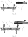
- the submarine vessel 2 When the submarine vessel 2 is in correct position, i.e. the primary coil 41 and the secondary coil 42 are aligned, the submarine vessel 2 lowers itself onto a precise position on the docking port 3, as shown in figure 6 .
- Figure 7A shows the magnetic field 5 emitted from the primary coil 41.
- the secondary coil 42 is positioned in the magnetic field 5 at a distance from the primary coil 41.
- the secondary coil 42 is positioned in a close vicinity of the primary coil 41, i.e. the secondary coil 42 is close to be in a position where electrical energy may be transferred from the primary coil 41 to the secondary coil 42.
- the outward facing portion 419 of the primary coil 41 is surrounded by a first metal ring 81.
- the outward facing portion 429 of the secondary coil 42 is surrounded by a second metal ring 82.
- the submarine vessel 2 may be provided with optionally X-Y sensors 9.
- the first metal ring 81 may in one embodiment project a distance from the surface of the outward facing portion 419 as shown in figure 7B . In an alternative embodiment the first metal ring 81 may be flush with the surface of the outward facing portion 419. In a further alternative embodiment, the first metal ring 81 may be retracted relative to the surface of the outward facing portion 419. The second metal ring 82 may project a distance from the surface of the outward facing portion 429 as shown in figure 7B . In an alternative embodiment the second metal ring 82 may be flush with the surface of the outward facing portion 429. In a further alternative embodiment, the second metal ring 82 may be retracted relative to the surface of the outward facing portion 429. The first metal ring 81 and the second metal ring 82 may abut when the submarine 2 is in correct position relative to the docking port 3 such that charging may commence by the inductive connector system 4.
- the X-Y sensors 9 are positioned to measure the magnetic field 5 when there is a distance between the primary coil 41 and the secondary coil 42. However, when the primary coil 41 and the secondary coil 42 are close as shown in figure 7B , the magnetic field 5 is distorted by the second metal ring 82 and may even be short-circuited by the second metal ring 82. Thereby the X-Y sensors 9 are screened from the magnetic field 5 or not able to make sensible readings of the strength or magnitude of the magnetic field 5.
- the electronics 6 comprises a charging branch 61 between the secondary coil 42 and a power output 44.
- the charging branch 61 comprises a rectifier 63, an optional resistor 64, a capacitor 65 and a voltage converter 66.
- the voltage converter 66 supplies a control electronic 7 with low voltage electrical power.
- the electronics 6 comprises a measuring branch 62.
- the measuring branch 62 branches from the charging branch 61 between the secondary coil 42 and the rectifier 63.
- the measuring branch 62 comprises a rectifier 623, a level converter 67 and a resistor 624.
- the measuring branch 62 delivers a low voltage output signal at a connection 68.
- the control electronics 7 is adapted to read the output signal at the connection 68.
- the strength of the output signal is a measurement of the strength of the magnetic field 5 that is received by the secondary coil 42.
- the electronics 6 comprises a means for inactivating the capacitor 65.
- the means is shown as a step-up converter 69.
- the step-up converter 69 is at the input side supplied by a low voltage energy source 690.
- the low voltage energy source 690 may be a battery (not shown).
- the step-up converter 69 is on the output side connected to the charging branch 61 between the rectifier 63 and the capacitor 65, or alternatively between the rectifier 63 and the optional resistor 64.
- the control electronics 7 communicates with a positioning electronics (not shown) of the submarine vessel 2.
- the secondary coil 42 is used to measure a portion of the local magnetic field emitted from the primary coil (41). In homing mode, the primary coil (41) operates at reduced power to save energy. The magnitude of the low output voltage signal at the connection 68 is dependent on the distance to the primary coil (41).
- the secondary coil (42) is used in the inductive connector system 4 to receive electrical power, it is necessary to provide the charging branch 61 with one or more capacitors (65) with high capacitance.
- the charging branch 61 may be used for a dual purpose.
- the charging branch 61 may measure the strength of the magnetic field 5 and the charging branch may be used to transfer electrical power. However, a significant time delay in the measurements will occur due to the capacitors (65). Such time delay is undesirable and a problem when positioning the submarine vessel 2.
- the capacitance may be inactivated by the means.
- the means may comprise a switch (not shown) or the like.
- a switch may also be used to inactivate other parts of the electronics 6 that may cause a time delay in the measurements.
- the means comprises the step-up converter 69.
- the step-up converter 69 induces a higher voltage to the capacitor 65 than is used in the voltage range for measuring the distance to the primary coil 41. Thereby the capacitor 65 is not charged and discharged during the measuring of distance.
- This also has the advantage that no switch is needed and the control electronic 7 is supplied with power from the voltage converter 66.
- the measuring branch 62 does not contain a capacitor and is used to measure the local magnetic field 5 without time delay.
- the secondary coil 42 When the primary coil 41 and the secondary coil 42 are aligned and in correct position as determined by the first metal ring 81 and the second metal ring 82, the secondary coil 42 will deliver a voltage that is higher than the voltage delivered by the step-up converter 69. Thereby the electronic 6 may swap from a measurement mode to a power supply mode. This swap of mode is a robust action.
- the first metal ring 81 and the second metal ring 82 secure that the inductive connector system is not damaged in case of a hard impact from the submarine vessel 2 onto the docking port 3 during docking.
- the submarine vessel 2 may descend towards the docking port 3 at an angle. Due to the protection provided by the first metal ring 81 and the second metal ring 82.
Landscapes
- Engineering & Computer Science (AREA)
- Power Engineering (AREA)
- Mechanical Engineering (AREA)
- Transportation (AREA)
- Computer Networks & Wireless Communication (AREA)
- Aviation & Aerospace Engineering (AREA)
- Radar, Positioning & Navigation (AREA)
- Remote Sensing (AREA)
- Physics & Mathematics (AREA)
- General Physics & Mathematics (AREA)
- Automation & Control Theory (AREA)
- Charge And Discharge Circuits For Batteries Or The Like (AREA)
- Geophysics And Detection Of Objects (AREA)
- Mechanical Means For Catching Fish (AREA)
Claims (4)
- Verfahren zum Andocken eines Unterwasserfahrzeugs (2) an einem Unterwasser-Andockport (3), wobei das Unterwasserfahrzeug (2) mit einem Unterwasser-Navigationssystem bereitgestellt ist, wobei das Unterwasserfahrzeug (2) zu einer ersten Position in einem ersten Abstand von dem Andockport (3) navigiert wird, dadurch gekennzeichnet, dass mindestens eine Primärspule (41) an dem Andockport (3) ein Magnetfeld (5) aussendet, und das Unterwasserfahrzeug (2) mit einer Elektronik (6) bereitgestellt ist, die angepasst ist, um die Stärke des Magnetfeldes (5) zu messen, das von einer zweiten Spule (42) auf dem Unterwasserfahrzeug (2) empfangen wird, wobei eine Positionierungselektronik das Unterwasserfahrzeug (2) durch Versuch und Irrtum in der horizontalen Ebene (X-Y-Ebene) führt, um eine Position zu lokalisieren, in der das von der zweiten Spule (42) empfangene Magnetfeld (5) ein lokales Maximum hat, und die Positionierungselektronik das Unterwasserfahrzeug (2) in der vertikalen Richtung (Z-Richtung) führt, bis das Unterwasserfahrzeug (2) korrekt an dem Andockport (3) angedockt ist.
- Verfahren nach Anspruch 1, wobei das Unterwasserfahrzeug (2) mit einer Elektronik (6) bereitgestellt ist, die einen mit der zweiten Spule (42) verbundenen Ladezweig (61) umfasst, und das Verfahren umfasst, dass eine Kapazität in dem Ladezweig (61) durch ein Mittel inaktiviert wird.
- Verfahren nach Anspruch 2, wobei die Kapazität durch Aktivieren eines Schalters inaktiviert wird.
- Verfahren nach Anspruch 2, wobei der Kondensator (65) durch Erhöhung der Spannung des Ladezweigs (61) durch Aktivierung eines Aufwärtswandlers (69) inaktiviert wird und das Magnetfeld (5) in einem mit der zweiten Spule (42) verbundenen Messzweig (62) gemessen wird.
Applications Claiming Priority (2)
| Application Number | Priority Date | Filing Date | Title |
|---|---|---|---|
| NO20181653 | 2018-12-19 | ||
| PCT/NO2019/050285 WO2020130849A1 (en) | 2018-12-19 | 2019-12-19 | System for docking a submarine vessel to a docking port and a method for docking the submarine vessel on the docking port |
Publications (4)
| Publication Number | Publication Date |
|---|---|
| EP3898405A1 EP3898405A1 (de) | 2021-10-27 |
| EP3898405A4 EP3898405A4 (de) | 2022-10-19 |
| EP3898405B1 true EP3898405B1 (de) | 2024-12-04 |
| EP3898405C0 EP3898405C0 (de) | 2024-12-04 |
Family
ID=71102703
Family Applications (1)
| Application Number | Title | Priority Date | Filing Date |
|---|---|---|---|
| EP19898061.7A Active EP3898405B1 (de) | 2018-12-19 | 2019-12-19 | System zum andocken eines unterwasserfahrzeugs an einen andockport und verfahren zum andocken des unterwasserfahrzeugs am andockport |
Country Status (5)
| Country | Link |
|---|---|
| US (1) | US11926232B2 (de) |
| EP (1) | EP3898405B1 (de) |
| BR (1) | BR112021011747A8 (de) |
| NO (1) | NO345899B1 (de) |
| WO (1) | WO2020130849A1 (de) |
Families Citing this family (5)
| Publication number | Priority date | Publication date | Assignee | Title |
|---|---|---|---|---|
| JP7297934B2 (ja) * | 2019-12-27 | 2023-06-26 | 川崎重工業株式会社 | 水中ドッキングシステム、潜水機、及び、水中ステーション |
| CN113984045B (zh) * | 2021-10-13 | 2024-01-16 | 湖南航天机电设备与特种材料研究所 | 水下机器人移动式对接目标运动状态估计方法及系统 |
| WO2024249283A1 (en) * | 2023-06-02 | 2024-12-05 | Drexel University | Universal wireless charging station for underwater robots and vehicles |
| CN119145807B (zh) * | 2024-08-30 | 2025-06-17 | 中国海洋大学 | 利用深海原位氢气能源的多金属结核采矿系统 |
| CN119636480B (zh) * | 2025-01-07 | 2025-10-28 | 中山大学 | 一种auv水下充电平台及水下充电方法 |
Family Cites Families (10)
| Publication number | Priority date | Publication date | Assignee | Title |
|---|---|---|---|---|
| GB0100106D0 (en) * | 2001-01-03 | 2001-02-14 | Flight Refueling Ltd | Subsea navigation and survey |
| GB201000662D0 (en) | 2010-01-15 | 2010-03-03 | Wireless Fibre Systems Ltd | Subsea wireless communication, navigation and power system |
| KR101138859B1 (ko) | 2011-06-30 | 2012-05-15 | 엘아이지넥스원 주식회사 | 자기유도선을 이용하는 무인 잠수정의 수중 도킹을 위한 시스템 및 그 방법 |
| CN105966578B (zh) | 2011-12-07 | 2018-04-06 | 株式会社 Ihi | 输电装置及受电装置 |
| EP2932517B1 (de) | 2012-12-14 | 2018-07-04 | Blue Logic AS | Vorrichtung zur induktiven übertragung von elektrischer energie |
| JP6277585B2 (ja) * | 2013-02-04 | 2018-02-14 | 株式会社Ihi | 非接触給電システム |
| WO2016153589A2 (en) * | 2015-01-23 | 2016-09-29 | Battelle Memorial Institute | Underwater power and data transfer system |
| US10291071B2 (en) * | 2016-01-19 | 2019-05-14 | The United States Of America As Represented By The Secretary Of The Navy | Wireless power and data transfer for unmanned vehicles |
| JP2017225272A (ja) * | 2016-06-16 | 2017-12-21 | 国立研究開発法人海洋研究開発機構 | 水中充電システム及び水中充電方法 |
| CN108680170A (zh) * | 2018-06-20 | 2018-10-19 | 浙江大学 | 基于电磁波衰减原理的auv回坞导航系统及方法 |
-
2019
- 2019-12-19 WO PCT/NO2019/050285 patent/WO2020130849A1/en not_active Ceased
- 2019-12-19 EP EP19898061.7A patent/EP3898405B1/de active Active
- 2019-12-19 US US17/415,341 patent/US11926232B2/en active Active
- 2019-12-19 NO NO20191499A patent/NO345899B1/en unknown
- 2019-12-19 BR BR112021011747A patent/BR112021011747A8/pt unknown
Also Published As
| Publication number | Publication date |
|---|---|
| WO2020130849A1 (en) | 2020-06-25 |
| EP3898405A1 (de) | 2021-10-27 |
| NO345899B1 (en) | 2021-10-04 |
| US11926232B2 (en) | 2024-03-12 |
| EP3898405C0 (de) | 2024-12-04 |
| EP3898405A4 (de) | 2022-10-19 |
| NO20191499A1 (en) | 2020-06-22 |
| US20220055494A1 (en) | 2022-02-24 |
| BR112021011747A8 (pt) | 2022-08-16 |
| BR112021011747A2 (pt) | 2021-08-31 |
Similar Documents
| Publication | Publication Date | Title |
|---|---|---|
| US11926232B2 (en) | System for docking a submarine vessel to a docking port and a method for docking the submarine vessel on the docking port | |
| US10279692B2 (en) | Electricity supply device and electricity reception device | |
| JP5479338B2 (ja) | 無人飛行ビークルの飛行中燃料給油方法およびシステム | |
| US9855852B2 (en) | Charging apparatus for unmanned aerial vehicles and method thereof | |
| ES2898674T3 (es) | Dispositivo para la transmisión de energía inductiva sin contacto y método de funcionamiento para un dispositivo de este tipo | |
| JP6836013B2 (ja) | 航空機充電方法及び装置 | |
| US11687088B2 (en) | Vehicular system | |
| JPS6394185A (ja) | 電磁波式識別位置決め装置 | |
| WO2018094271A1 (en) | Long distance positioning guide for wireless power | |
| JP2013150430A (ja) | 非接触給電装置 | |
| CN105751908A (zh) | 给交通运输工具蓄电池充电的方法 | |
| CN108957402A (zh) | 读取装置、传感器装置及传感系统 | |
| CN107168373A (zh) | 一种无人机定点降落系统及方法 | |
| KR20190129446A (ko) | 무인 항공기의 착륙 유도 방법 및 그를 위한 장치 | |
| EP3852236A1 (de) | Vorrichtung zur kontaktfreien stromübertragung unter wasser | |
| JP6006857B2 (ja) | 送電装置 | |
| KR101786491B1 (ko) | 착륙 보조장치를 이용한 비행체의 자동착륙 시스템 | |
| US20170126060A1 (en) | Wireless power supply system and wireless power reception device | |
| US20170328977A1 (en) | Position determination apparatus | |
| KR20180055167A (ko) | 항공 및 해상 화물의 운송상태 확인장치 | |
| EP3511195B1 (de) | Fahrassistenzsystem und verfahren zur führung eines fahrzeugs oder eines fahrers des fahrzeugs zu einer ladestation | |
| CN115514029A (zh) | 一种地面移动充电设备被动式自动无线充电的方法 | |
| US20210152032A1 (en) | Power transmission device, power reception device, wireless power transmission system, and method for driving power transmission device | |
| EP4083741A1 (de) | Verfahren und system zum laden eines roboterarbeitswerkzeugs | |
| EP3511194B1 (de) | Fahrassistenzsystem und verfahren zur positionierung eines fahrzeugs über eine ladestation |
Legal Events
| Date | Code | Title | Description |
|---|---|---|---|
| STAA | Information on the status of an ep patent application or granted ep patent |
Free format text: STATUS: THE INTERNATIONAL PUBLICATION HAS BEEN MADE |
|
| PUAI | Public reference made under article 153(3) epc to a published international application that has entered the european phase |
Free format text: ORIGINAL CODE: 0009012 |
|
| STAA | Information on the status of an ep patent application or granted ep patent |
Free format text: STATUS: REQUEST FOR EXAMINATION WAS MADE |
|
| 17P | Request for examination filed |
Effective date: 20210615 |
|
| AK | Designated contracting states |
Kind code of ref document: A1 Designated state(s): AL AT BE BG CH CY CZ DE DK EE ES FI FR GB GR HR HU IE IS IT LI LT LU LV MC MK MT NL NO PL PT RO RS SE SI SK SM TR |
|
| RAP1 | Party data changed (applicant data changed or rights of an application transferred) |
Owner name: WPC WIRELESS POWER AND COMMUNICATION AS |
|
| DAV | Request for validation of the european patent (deleted) | ||
| DAX | Request for extension of the european patent (deleted) | ||
| A4 | Supplementary search report drawn up and despatched |
Effective date: 20220915 |
|
| RIC1 | Information provided on ipc code assigned before grant |
Ipc: H01F 38/14 20060101ALI20220909BHEP Ipc: B63C 11/00 20060101ALI20220909BHEP Ipc: B63G 8/00 20060101AFI20220909BHEP |
|
| STAA | Information on the status of an ep patent application or granted ep patent |
Free format text: STATUS: EXAMINATION IS IN PROGRESS |
|
| 17Q | First examination report despatched |
Effective date: 20240222 |
|
| RAP3 | Party data changed (applicant data changed or rights of an application transferred) |
Owner name: UNPLUGGED AS |
|
| GRAP | Despatch of communication of intention to grant a patent |
Free format text: ORIGINAL CODE: EPIDOSNIGR1 |
|
| STAA | Information on the status of an ep patent application or granted ep patent |
Free format text: STATUS: GRANT OF PATENT IS INTENDED |
|
| INTG | Intention to grant announced |
Effective date: 20240905 |
|
| GRAS | Grant fee paid |
Free format text: ORIGINAL CODE: EPIDOSNIGR3 |
|
| GRAA | (expected) grant |
Free format text: ORIGINAL CODE: 0009210 |
|
| STAA | Information on the status of an ep patent application or granted ep patent |
Free format text: STATUS: THE PATENT HAS BEEN GRANTED |
|
| AK | Designated contracting states |
Kind code of ref document: B1 Designated state(s): AL AT BE BG CH CY CZ DE DK EE ES FI FR GB GR HR HU IE IS IT LI LT LU LV MC MK MT NL NO PL PT RO RS SE SI SK SM TR |
|
| REG | Reference to a national code |
Ref country code: CH Ref legal event code: EP |
|
| REG | Reference to a national code |
Ref country code: DE Ref legal event code: R096 Ref document number: 602019063200 Country of ref document: DE |
|
| REG | Reference to a national code |
Ref country code: IE Ref legal event code: FG4D |
|
| U01 | Request for unitary effect filed |
Effective date: 20250103 |
|
| U07 | Unitary effect registered |
Designated state(s): AT BE BG DE DK EE FI FR IT LT LU LV MT NL PT RO SE SI Effective date: 20250114 |
|
| U20 | Renewal fee for the european patent with unitary effect paid |
Year of fee payment: 6 Effective date: 20250120 |
|
| PG25 | Lapsed in a contracting state [announced via postgrant information from national office to epo] |
Ref country code: HR Free format text: LAPSE BECAUSE OF FAILURE TO SUBMIT A TRANSLATION OF THE DESCRIPTION OR TO PAY THE FEE WITHIN THE PRESCRIBED TIME-LIMIT Effective date: 20241204 |
|
| PG25 | Lapsed in a contracting state [announced via postgrant information from national office to epo] |
Ref country code: ES Free format text: LAPSE BECAUSE OF FAILURE TO SUBMIT A TRANSLATION OF THE DESCRIPTION OR TO PAY THE FEE WITHIN THE PRESCRIBED TIME-LIMIT Effective date: 20241204 |
|
| PG25 | Lapsed in a contracting state [announced via postgrant information from national office to epo] |
Ref country code: NO Free format text: LAPSE BECAUSE OF FAILURE TO SUBMIT A TRANSLATION OF THE DESCRIPTION OR TO PAY THE FEE WITHIN THE PRESCRIBED TIME-LIMIT Effective date: 20250304 |
|
| PG25 | Lapsed in a contracting state [announced via postgrant information from national office to epo] |
Ref country code: GR Free format text: LAPSE BECAUSE OF FAILURE TO SUBMIT A TRANSLATION OF THE DESCRIPTION OR TO PAY THE FEE WITHIN THE PRESCRIBED TIME-LIMIT Effective date: 20250305 |
|
| PG25 | Lapsed in a contracting state [announced via postgrant information from national office to epo] |
Ref country code: RS Free format text: LAPSE BECAUSE OF FAILURE TO SUBMIT A TRANSLATION OF THE DESCRIPTION OR TO PAY THE FEE WITHIN THE PRESCRIBED TIME-LIMIT Effective date: 20250304 |
|
| PG25 | Lapsed in a contracting state [announced via postgrant information from national office to epo] |
Ref country code: SM Free format text: LAPSE BECAUSE OF FAILURE TO SUBMIT A TRANSLATION OF THE DESCRIPTION OR TO PAY THE FEE WITHIN THE PRESCRIBED TIME-LIMIT Effective date: 20241204 |
|
| PG25 | Lapsed in a contracting state [announced via postgrant information from national office to epo] |
Ref country code: PL Free format text: LAPSE BECAUSE OF FAILURE TO SUBMIT A TRANSLATION OF THE DESCRIPTION OR TO PAY THE FEE WITHIN THE PRESCRIBED TIME-LIMIT Effective date: 20241204 |
|
| PG25 | Lapsed in a contracting state [announced via postgrant information from national office to epo] |
Ref country code: IS Free format text: LAPSE BECAUSE OF FAILURE TO SUBMIT A TRANSLATION OF THE DESCRIPTION OR TO PAY THE FEE WITHIN THE PRESCRIBED TIME-LIMIT Effective date: 20250404 |
|
| PG25 | Lapsed in a contracting state [announced via postgrant information from national office to epo] |
Ref country code: SK Free format text: LAPSE BECAUSE OF FAILURE TO SUBMIT A TRANSLATION OF THE DESCRIPTION OR TO PAY THE FEE WITHIN THE PRESCRIBED TIME-LIMIT Effective date: 20241204 |
|
| PG25 | Lapsed in a contracting state [announced via postgrant information from national office to epo] |
Ref country code: CZ Free format text: LAPSE BECAUSE OF FAILURE TO SUBMIT A TRANSLATION OF THE DESCRIPTION OR TO PAY THE FEE WITHIN THE PRESCRIBED TIME-LIMIT Effective date: 20241204 |
|
| REG | Reference to a national code |
Ref country code: CH Ref legal event code: PL |
|
| PG25 | Lapsed in a contracting state [announced via postgrant information from national office to epo] |
Ref country code: MC Free format text: LAPSE BECAUSE OF FAILURE TO SUBMIT A TRANSLATION OF THE DESCRIPTION OR TO PAY THE FEE WITHIN THE PRESCRIBED TIME-LIMIT Effective date: 20241204 |
|
| PLBE | No opposition filed within time limit |
Free format text: ORIGINAL CODE: 0009261 |
|
| STAA | Information on the status of an ep patent application or granted ep patent |
Free format text: STATUS: NO OPPOSITION FILED WITHIN TIME LIMIT |
|
| PG25 | Lapsed in a contracting state [announced via postgrant information from national office to epo] |
Ref country code: CH Free format text: LAPSE BECAUSE OF NON-PAYMENT OF DUE FEES Effective date: 20241231 |
|
| PG25 | Lapsed in a contracting state [announced via postgrant information from national office to epo] |
Ref country code: IE Free format text: LAPSE BECAUSE OF NON-PAYMENT OF DUE FEES Effective date: 20241219 |
|
| 26N | No opposition filed |
Effective date: 20250905 |
|
| GBPC | Gb: european patent ceased through non-payment of renewal fee |
Effective date: 20250304 |
|
| PG25 | Lapsed in a contracting state [announced via postgrant information from national office to epo] |
Ref country code: GB Free format text: LAPSE BECAUSE OF NON-PAYMENT OF DUE FEES Effective date: 20250304 |
|
| U20 | Renewal fee for the european patent with unitary effect paid |
Year of fee payment: 7 Effective date: 20251212 |
|
| PG25 | Lapsed in a contracting state [announced via postgrant information from national office to epo] |
Ref country code: CY Free format text: LAPSE BECAUSE OF FAILURE TO SUBMIT A TRANSLATION OF THE DESCRIPTION OR TO PAY THE FEE WITHIN THE PRESCRIBED TIME-LIMIT Effective date: 20241204 |