EP3898436B1 - Fermeture de boîte à boisson, boîte à boisson et méthode de fabrication d'une fermeture de boîte à boisson - Google Patents
Fermeture de boîte à boisson, boîte à boisson et méthode de fabrication d'une fermeture de boîte à boisson Download PDFInfo
- Publication number
- EP3898436B1 EP3898436B1 EP19818097.8A EP19818097A EP3898436B1 EP 3898436 B1 EP3898436 B1 EP 3898436B1 EP 19818097 A EP19818097 A EP 19818097A EP 3898436 B1 EP3898436 B1 EP 3898436B1
- Authority
- EP
- European Patent Office
- Prior art keywords
- lid
- closure element
- actuating element
- closed position
- opening
- Prior art date
- Legal status (The legal status is an assumption and is not a legal conclusion. Google has not performed a legal analysis and makes no representation as to the accuracy of the status listed.)
- Active
Links
Images






Classifications
-
- B—PERFORMING OPERATIONS; TRANSPORTING
- B65—CONVEYING; PACKING; STORING; HANDLING THIN OR FILAMENTARY MATERIAL
- B65D—CONTAINERS FOR STORAGE OR TRANSPORT OF ARTICLES OR MATERIALS, e.g. BAGS, BARRELS, BOTTLES, BOXES, CANS, CARTONS, CRATES, DRUMS, JARS, TANKS, HOPPERS, FORWARDING CONTAINERS; ACCESSORIES, CLOSURES, OR FITTINGS THEREFOR; PACKAGING ELEMENTS; PACKAGES
- B65D17/00—Rigid or semi-rigid containers specially constructed to be opened by cutting or piercing, or by tearing of frangible members or portions
- B65D17/50—Non-integral frangible members applied to, or inserted in, preformed openings, e.g. tearable strips or plastic plugs
- B65D17/506—Rigid or semi-rigid members, e.g. plugs
-
- B—PERFORMING OPERATIONS; TRANSPORTING
- B65—CONVEYING; PACKING; STORING; HANDLING THIN OR FILAMENTARY MATERIAL
- B65D—CONTAINERS FOR STORAGE OR TRANSPORT OF ARTICLES OR MATERIALS, e.g. BAGS, BARRELS, BOTTLES, BOXES, CANS, CARTONS, CRATES, DRUMS, JARS, TANKS, HOPPERS, FORWARDING CONTAINERS; ACCESSORIES, CLOSURES, OR FITTINGS THEREFOR; PACKAGING ELEMENTS; PACKAGES
- B65D47/00—Closures with filling and discharging, or with discharging, devices
- B65D47/04—Closures with discharging devices other than pumps
- B65D47/20—Closures with discharging devices other than pumps comprising hand-operated members for controlling discharge
- B65D47/26—Closures with discharging devices other than pumps comprising hand-operated members for controlling discharge with slide valves, i.e. valves that open and close a passageway by sliding over a port, e.g. formed with slidable spouts
- B65D47/28—Closures with discharging devices other than pumps comprising hand-operated members for controlling discharge with slide valves, i.e. valves that open and close a passageway by sliding over a port, e.g. formed with slidable spouts having linear movement
- B65D47/286—Closures with discharging devices other than pumps comprising hand-operated members for controlling discharge with slide valves, i.e. valves that open and close a passageway by sliding over a port, e.g. formed with slidable spouts having linear movement between planar parts
-
- B—PERFORMING OPERATIONS; TRANSPORTING
- B65—CONVEYING; PACKING; STORING; HANDLING THIN OR FILAMENTARY MATERIAL
- B65D—CONTAINERS FOR STORAGE OR TRANSPORT OF ARTICLES OR MATERIALS, e.g. BAGS, BARRELS, BOTTLES, BOXES, CANS, CARTONS, CRATES, DRUMS, JARS, TANKS, HOPPERS, FORWARDING CONTAINERS; ACCESSORIES, CLOSURES, OR FITTINGS THEREFOR; PACKAGING ELEMENTS; PACKAGES
- B65D53/00—Sealing or packing elements; Sealings formed by liquid or plastics material
- B65D53/02—Collars or rings
-
- B—PERFORMING OPERATIONS; TRANSPORTING
- B65—CONVEYING; PACKING; STORING; HANDLING THIN OR FILAMENTARY MATERIAL
- B65D—CONTAINERS FOR STORAGE OR TRANSPORT OF ARTICLES OR MATERIALS, e.g. BAGS, BARRELS, BOTTLES, BOXES, CANS, CARTONS, CRATES, DRUMS, JARS, TANKS, HOPPERS, FORWARDING CONTAINERS; ACCESSORIES, CLOSURES, OR FITTINGS THEREFOR; PACKAGING ELEMENTS; PACKAGES
- B65D85/00—Containers, packaging elements or packages, specially adapted for particular articles or materials
- B65D85/70—Containers, packaging elements or packages, specially adapted for particular articles or materials for materials not otherwise provided for
- B65D85/72—Containers, packaging elements or packages, specially adapted for particular articles or materials for materials not otherwise provided for for edible or potable liquids, semiliquids, or plastic or pasty materials
-
- B—PERFORMING OPERATIONS; TRANSPORTING
- B65—CONVEYING; PACKING; STORING; HANDLING THIN OR FILAMENTARY MATERIAL
- B65D—CONTAINERS FOR STORAGE OR TRANSPORT OF ARTICLES OR MATERIALS, e.g. BAGS, BARRELS, BOTTLES, BOXES, CANS, CARTONS, CRATES, DRUMS, JARS, TANKS, HOPPERS, FORWARDING CONTAINERS; ACCESSORIES, CLOSURES, OR FITTINGS THEREFOR; PACKAGING ELEMENTS; PACKAGES
- B65D2205/00—Venting means
-
- B—PERFORMING OPERATIONS; TRANSPORTING
- B65—CONVEYING; PACKING; STORING; HANDLING THIN OR FILAMENTARY MATERIAL
- B65D—CONTAINERS FOR STORAGE OR TRANSPORT OF ARTICLES OR MATERIALS, e.g. BAGS, BARRELS, BOTTLES, BOXES, CANS, CARTONS, CRATES, DRUMS, JARS, TANKS, HOPPERS, FORWARDING CONTAINERS; ACCESSORIES, CLOSURES, OR FITTINGS THEREFOR; PACKAGING ELEMENTS; PACKAGES
- B65D2205/00—Venting means
- B65D2205/02—Venting holes
-
- B—PERFORMING OPERATIONS; TRANSPORTING
- B65—CONVEYING; PACKING; STORING; HANDLING THIN OR FILAMENTARY MATERIAL
- B65D—CONTAINERS FOR STORAGE OR TRANSPORT OF ARTICLES OR MATERIALS, e.g. BAGS, BARRELS, BOTTLES, BOXES, CANS, CARTONS, CRATES, DRUMS, JARS, TANKS, HOPPERS, FORWARDING CONTAINERS; ACCESSORIES, CLOSURES, OR FITTINGS THEREFOR; PACKAGING ELEMENTS; PACKAGES
- B65D2401/00—Tamper-indicating means
- B65D2401/15—Tearable part of the closure
-
- B—PERFORMING OPERATIONS; TRANSPORTING
- B65—CONVEYING; PACKING; STORING; HANDLING THIN OR FILAMENTARY MATERIAL
- B65D—CONTAINERS FOR STORAGE OR TRANSPORT OF ARTICLES OR MATERIALS, e.g. BAGS, BARRELS, BOTTLES, BOXES, CANS, CARTONS, CRATES, DRUMS, JARS, TANKS, HOPPERS, FORWARDING CONTAINERS; ACCESSORIES, CLOSURES, OR FITTINGS THEREFOR; PACKAGING ELEMENTS; PACKAGES
- B65D2517/00—Containers specially constructed to be opened by cutting, piercing or tearing of wall portions, e.g. preserving cans or tins
- B65D2517/0001—Details
- B65D2517/0031—Reclosable openings
- B65D2517/004—Reclosable openings by means of an additional element
-
- B—PERFORMING OPERATIONS; TRANSPORTING
- B65—CONVEYING; PACKING; STORING; HANDLING THIN OR FILAMENTARY MATERIAL
- B65D—CONTAINERS FOR STORAGE OR TRANSPORT OF ARTICLES OR MATERIALS, e.g. BAGS, BARRELS, BOTTLES, BOXES, CANS, CARTONS, CRATES, DRUMS, JARS, TANKS, HOPPERS, FORWARDING CONTAINERS; ACCESSORIES, CLOSURES, OR FITTINGS THEREFOR; PACKAGING ELEMENTS; PACKAGES
- B65D2517/00—Containers specially constructed to be opened by cutting, piercing or tearing of wall portions, e.g. preserving cans or tins
- B65D2517/0001—Details
- B65D2517/0031—Reclosable openings
- B65D2517/0046—Unusual reclosable openings
-
- B—PERFORMING OPERATIONS; TRANSPORTING
- B65—CONVEYING; PACKING; STORING; HANDLING THIN OR FILAMENTARY MATERIAL
- B65D—CONTAINERS FOR STORAGE OR TRANSPORT OF ARTICLES OR MATERIALS, e.g. BAGS, BARRELS, BOTTLES, BOXES, CANS, CARTONS, CRATES, DRUMS, JARS, TANKS, HOPPERS, FORWARDING CONTAINERS; ACCESSORIES, CLOSURES, OR FITTINGS THEREFOR; PACKAGING ELEMENTS; PACKAGES
- B65D2517/00—Containers specially constructed to be opened by cutting, piercing or tearing of wall portions, e.g. preserving cans or tins
- B65D2517/0001—Details
- B65D2517/0091—Means for venting upon initial opening
-
- B—PERFORMING OPERATIONS; TRANSPORTING
- B65—CONVEYING; PACKING; STORING; HANDLING THIN OR FILAMENTARY MATERIAL
- B65D—CONTAINERS FOR STORAGE OR TRANSPORT OF ARTICLES OR MATERIALS, e.g. BAGS, BARRELS, BOTTLES, BOXES, CANS, CARTONS, CRATES, DRUMS, JARS, TANKS, HOPPERS, FORWARDING CONTAINERS; ACCESSORIES, CLOSURES, OR FITTINGS THEREFOR; PACKAGING ELEMENTS; PACKAGES
- B65D2517/00—Containers specially constructed to be opened by cutting, piercing or tearing of wall portions, e.g. preserving cans or tins
- B65D2517/0001—Details
- B65D2517/0091—Means for venting upon initial opening
- B65D2517/0094—Means for venting upon initial opening formed as a separate opening
-
- Y—GENERAL TAGGING OF NEW TECHNOLOGICAL DEVELOPMENTS; GENERAL TAGGING OF CROSS-SECTIONAL TECHNOLOGIES SPANNING OVER SEVERAL SECTIONS OF THE IPC; TECHNICAL SUBJECTS COVERED BY FORMER USPC CROSS-REFERENCE ART COLLECTIONS [XRACs] AND DIGESTS
- Y02—TECHNOLOGIES OR APPLICATIONS FOR MITIGATION OR ADAPTATION AGAINST CLIMATE CHANGE
- Y02W—CLIMATE CHANGE MITIGATION TECHNOLOGIES RELATED TO WASTEWATER TREATMENT OR WASTE MANAGEMENT
- Y02W30/00—Technologies for solid waste management
- Y02W30/50—Reuse, recycling or recovery technologies
- Y02W30/80—Packaging reuse or recycling, e.g. of multilayer packaging
Definitions
- the present invention relates to a can lid.
- the invention also relates to a can and a method for producing a can lid.
- Drinks cans with a cylindrical container made of aluminum or tinplate are well known.
- a lid is folded over on top, to which a metal tab is riveted as an opener.
- a scored oval line is broken and part of the lid is pressed into the inside of the can to reveal a drinking opening.
- the disadvantage of this is that the drinks can cannot be closed again. This means that any drink inside quickly goes stale. In addition, the drink can easily be spilled during further transport.
- Resealable can lids are also known.
- a can lid is described in which a closure element on the bottom can be pivoted between a closed position and an open position by an actuating element on the top.
- the closure element and the actuating element are large components, which is disadvantageous during filling.
- the can lid is heavy and expensive.
- the actuating element and the closure element are usually made of plastic, which makes recycling difficult.
- the rotary movement also requires high actuating forces and places unfavorable loads on the components, for example with a strong shear force.
- a closure device with a closure device for re-closing a can opening comprising an inner element and an outer element, which are designed so that a can wall can be arranged between them in a sandwich-like manner.
- the inner element comprises a connecting device on its side facing the can wall.
- An actuating device is arranged outside the can, wherein the outer element is arranged between the actuating device and the inner element and the actuating device is movably connected to the connecting device, so that the outer element is indirectly connected to the inner element at a variable distance via the actuating device.
- the object of the present invention is to improve a can lid which is reclosable. Furthermore, the object of the invention is to improve a method for producing a reclosable can lid and a reclosable can.
- the can lid has at least one lid surface which is designed to delimit an upper side of the can, preferably by flanging an outer peripheral edge of the lid surface with a side wall of the can.
- the lid surface can correspond, for example, to a lid of a conventional beverage can.
- the lid surface can be made of aluminum or tinplate, optionally with a plastic coating, for example as corrosion protection.
- the lid surface has at least one pouring opening through which a substance in the can can be poured out. The pouring opening is preferably always provided in the lid surface. The pouring opening is therefore not, as is usual with beverage cans, only broken open by a metal tab when it is opened for the first time.
- the can lid has an actuating element which is arranged on an upper side of the lid surface, which faces away from an interior of the can when the can lid is attached to it.
- the can lid has a closure element which is arranged on an underside of the lid surface, which faces an interior of the can when the can lid is attached to it.
- the closure element can be moved essentially translationally along the lid surface by means of the actuating element between a closed position in which the closure element closes the pouring opening in a fluid-tight and/or gas-tight manner, and an open position in which the pouring opening is at least partially exposed.
- the translational movement is very intuitive, places little strain on a connection between the closure element and the actuating element, and requires low actuating forces.
- the locking element and the actuating element are made of a metallic material, preferably from an aluminum material or tinplate. This facilitates recycling.
- the closure element and/or the actuating element is made of the same materials as the lid surface and/or a body of the can, whereby preferably the entire can can be recycled without dismantling.
- the closure element and/or the actuating element can be made of tinplate or aluminum sheet and optionally have a plastic layer for corrosion protection. The plastic layer is preferably provided on both the inside and the outside of the lid panel, the closure element, the actuating element and/or the can body.
- the closure element is preferably not flat on its top and/or bottom side.
- the closure element can have one or more recesses or one or more protruding areas on its top side.
- a recess can be formed, for example, in the area of a rivet nipple or in a recessed area of the bottom side corresponding to this rivet nipple.
- a protruding area can, for example, be formed on the bottom side corresponding to an air channel running on the top side of the closure element.
- connection is fixed and/or its length is not variable. In other words, the distance between the actuating element and closure element in the area of the connection is fixed and/or not variable. This enables, among other things, automatic adjustment of the contact pressure of the closure element on the lid, which is discussed in more detail below.
- the closure element and the actuating element are fastened to one another by means of a connection that does not penetrate the closure element.
- a connection that does not penetrate the closure element.
- This reliably protects the contents of the can. In particular, this can prevent unwanted leaks when the lid is closed.
- Such a connection is advantageous when metallic materials are used for the closure element and/or actuating element, since a through-opening for the connection can only be sealed with great effort and tends to leak under pressure.
- a riveted connection is particularly suitable.
- a riveted connection can withstand large forces, for example in the event of improper operation, particularly well.
- riveting techniques enable high production rates with low waste.
- a welded connection is also particularly suitable, since little material is required.
- the actuating element and the closure element can be joined together using ultrasound or friction welding. be fastened together, in particular when plastics are used to manufacture the closure element and/or the actuating element.
- connection When the closure element is moved from the closed position to the open position, the connection is moved along a guide slot in the lid surface.
- the connection in particular a rivet, rivet area and/or weld area, can therefore be arranged in a plane defined by the lid surface.
- the connection can penetrate the lid surface, i.e. be arranged in a through-opening of the lid surface.
- the connection can thus serve as a guide.
- the overall height of the can lid can be particularly flat, which results in advantages during filling. For example, the overall height determines how many can lids can be provided in a magazine. Thin resealable can lids allow similar magazine fillings to non-resealable can lids, which means that the production rate is the same or only slightly lower than for non-resealable cans on the same filling line.
- the lid surface preferably has an outer diameter of at least 4.5 cm, at least 5 cm or at least 5.5 cm.
- the lid surface can correspond in its outer dimensions, apart from through-openings, to a standardized lid surface of beverage cans, in particular a B64 or CDL lid surface.
- the B64 lid surface can be, for example, of type 200, 202, 204, 206 or 209.
- the CDL lid surface can be, for example, of type 200 or 202.
- the lid surface can be essentially flat and/or round, preferably circular.
- the lid surface can have a circumferential bead, which increases its stability and helps to form the folded edge.
- the lid surface can also be referred to as a shell.
- All metal parts of the can lid are preferably coated with plastic or covered with a plastic film on the flat side facing the storage space of the can, and preferably also on the flat side facing away. This serves to protect against corrosion and the material stored in the can. For example, this can prevent metal from dissolving due to a liquid in the can. It can also prevent metal particles from getting into a drink.
- the lid surface, the actuating element and/or the closure element can be made of the metallic material, in particular only one and/or the same metallic material.
- the closure element can be essentially flat and/or round
- the can for which the can lid is intended is preferably intended for storing a drink, a soup or a bulk product.
- the drink can contain, for example, fibers, such as pulp in orange juice.
- the bulk product can be, for example, a spice.
- Soup can contain, for example, piece goods such as noodles, pieces of meat, etc.
- the pouring opening is preferably large enough to be able to pour these out.
- the closure element can release a pouring opening in the open position which is larger than solid bodies in the can.
- the pouring opening can be a through-opening from an interior to the outside of the can.
- a cross-sectional area of the pouring opening is preferably at least 1.5 cm 2 , more preferably at least 1.8 cm 2 and most preferably at least 2 cm 2 .
- the pouring opening preferably has an oval, circular or crescent shape.
- a front edge region of the pouring opening in the longitudinal direction of the guide slot and a rear edge region of the pouring opening in the longitudinal direction of the guide slot are preferably arched and/or curved. In this case, both a front edge region and a rear edge region are preferably curved in the same direction.
- the lid surface forms two tongues protruding into the pouring opening at the edge region of the pouring opening where the guide slot is arranged. The connection can be guided by these tongues in a frontmost position of the closure element.
- the guide slot is a through-opening in the cover panel.
- the guide slot is preferably designed as an elongated opening.
- the width of the guide slot can be essentially constant over its length.
- the guide slot specifies the translational movement of the closure element and actuating element between the closed position and the open position. At least a partial area of the closure element and/or the actuating element can be guided through the guide slot, for example by this partial area resting against an edge of the cover panel delimiting the guide slot.
- Respective lateral walls of the guide slot which preferably form a radially inner edge of the cover panel and/or are an edge of the cover panel, can therefore form a guide.
- the pouring opening and/or the guide slot are preferably punched out. These can be punched out passage areas in the lid surface.
- the closure element can seal the interior from the pouring opening in the closed position, for example by means of a seal and/or by pressing it against the lid surface. This pressing can be brought about by a pre-tension and/or the connection to the actuating element.
- the actuating element can move together with the closure element, i.e. also preferably guided essentially translationally along the lid surface. Through their connection, for example through the rivet connection, the actuating element and closure element are permanently connected to one another during normal use. During intended use, such as opening and closing the can, it is preferably not intended that the actuating element and the closure element are separated from one another.
- connection can be designed to hold the actuating element and the closure element to the lid surface.
- the connection in particular the rivet connection, is preferably under a pre-tension.
- the actuating element can be curved by the pre-tension.
- the camber is preferably designed in a direction that is reduced by increased internal pressure and/or pressing on the actuating element. This makes opening easier.
- the closure element In the closed position, the closure element preferably covers the pouring opening and the guide slot in a gas-tight and/or fluid-tight manner.
- the closure element preferably extends further over the lid surface than the pouring opening and guide slot together.
- the closure element is preferably rotationally symmetrical, which enables easier processing when producing the closure.
- respective outer edges of the closure element are preferably arranged radially outside respective through-openings in the lid surface.
- a diameter and/or a length of the closure element, in particular a diameter and/or a width of an area surrounded by a seal of the closure element, is preferably greater than a length between a front point of the pouring opening, in particular an apex of the pouring opening, and an opposite rear end of the guide slot.
- the actuating element preferably extends further over the lid surface than the pouring opening and guide slot together, in particular in the closed position.
- the actuating element covers the pouring opening and the guide slot in the closed position. This can prevent the accumulation of dirt on the closure element, in the guide slot and/or in the pouring opening.
- the closure element is preferably designed such that it completely overlaps the pouring opening and/or the guide slot in the closed position. In the open position, the closure element exposes at least 50%, preferably at least 70% and more preferably at least 90%, of the area of the outlet opening. The can contents are therefore immediately accessible through the exposed area, for example via a straw.
- the top of the can lid and/or respective parts can also be referred to as the outside.
- the bottom can also be referred to as the inside.
- a single connection for example the rivet connection or a single welding point, is provided between the actuating element and the closure element. This makes the production of the can lid particularly quick and cost-effective.
- the connection is formed by a nipple formed in the closure element or the actuating element, which is connected to the corresponding other element.
- the nipple can be riveted or welded.
- a nipple formed as a rivet nipple can be arranged in a corresponding rivet opening of the other of the two elements.
- the nipple is embossed.
- the metal sheet from which the element with the nipple is formed can be embossed to form the nipple.
- the nipple is preferably formed in one piece in the element.
- the nipple can be formed as a protruding area.
- the rivet nipple means that a separate component as a rivet can be dispensed with and also piercing the closure element to form the connection. In the case of welding, the nipple can also be used to specify a defined welding area.
- a similar rivet connection holds the metal tab, which is riveted to the lid surface of conventional beverage cans as a built-in can opener. Riveting can be carried out using Therefore, the systems for conventional cans are preferably used, which makes it particularly cost-effective to convert them to produce the resealable can lid.
- the rivet nipple is preferably formed in the closure element and protrudes towards the top.
- the rivet opening can be a through-opening and is preferably formed in the actuating element.
- the connection can therefore be designed in such a way that it does not penetrate the closure element.
- the rivet opening preferably extends through a projection, in particular through a projection of the actuating element that projects in the direction of the underside of the lid surface.
- the projection allows the overall thickness of the can lid to be small.
- the projection can preferably extend into the guide slot.
- the projection can preferably be produced by embossing.
- the projection can be formed by a recess in the actuating element opposite a surrounding flat area.
- the adjoining area is preferably the fastening section of the actuating element, which will be described later.
- the rivet opening is preferably arranged in the fastening section, in particular in the middle.
- the projection can protrude in the direction of the element with the rivet nipple.
- the projection preferably protrudes from the underside of the actuating element.
- the projection can, for example, protrude from an imaginary plane in which the fastening section is arranged.
- the projection extends at least partially through the guide slot in the open position and/or in the closed position.
- the projection extends at least partially through the guide slot in the open position and in the closed position.
- the projection can thus also serve as part of the guide. In addition, this preferably provides a safeguard against twisting of the actuating element.
- the projection In the closed position, the projection can also extend at least partially through the pouring opening.
- connection in particular designed as a rivet connection
- the connection is narrower than the guide slot at least in a region that extends through the guide slot.
- the projection can be narrower than the guide slot at least in a region that extends through the guide slot.
- the connection is preferably narrower than the guide slot at least in a region that extends above and/or below the Guide slot extends, wider than the guide slot.
- the width is preferably measured in the plane of the cover mirror. This plane can, for example, correspond to the plane in which the guide slot is formed.
- the width is preferably measured transversely to a longitudinal axis which extends between a front opening of the guide slot and a rear end of the guide slot, in particular orthogonal to this longitudinal axis.
- the width can also be orthogonal to a vertical direction.
- the thickness can be measured in the vertical direction.
- the vertical direction is preferably perpendicular to the plane in which the cover mirror extends.
- At least one flat surface is formed on the connection in an area that extends through the guide slot, wherein the at least one flat surface preferably faces an edge of the cover panel that delimits the guide slot.
- This flat surface allows the connection to be supported on the guide slot and thus function particularly well as an anti-twist device.
- at least two flat surfaces are formed on the connection in an area that extends through the guide slot. The two flat surfaces are preferably formed on opposite sides and/or substantially parallel.
- the at least one flat surface is formed on the projection.
- the at least two flat surfaces are formed on the projection. The respective flat surfaces can be supported on the edge of the cover panel that delimits the guide slot and provide an anti-twist device.
- the rivet opening and/or a remaining projection are preferably round, in particular circular.
- the round shape can be flattened.
- the nipple, in particular the rivet nipple can be round, in particular circular.
- the respective flat surfaces preferably extend in a direction perpendicular to the plane of the cover surface, i.e. in the vertical or vertical direction, and/or parallel to the longitudinal axis of the guide slot and/or parallel to the edge of the cover surface delimiting the guide slot.
- a curved, stepped or toothed surface can also be provided, which provides at least two defined contact points with the edge of the cover surface delimiting the guide slot. This can also provide an anti-twisting device.
- an additional projection for guidance can be provided on the closure and/or actuating element.
- the can lid preferably has at least one seal, which is arranged between the closure element and the lid surface at least in the closed position of the closure element.
- the seal is preferably made of a softer material than the closure element. Silicone, rubber, elastomers, thermoplastics or elastomeric thermoplastics can be used in particular. This enables safe and pressure-tight reclosure to be reliably achieved.
- a single seal is provided, which seals the closure element against the lid surface at contact points.
- the closure element has a support area in the area of the connection to the actuating element.
- the closure element only rests on the lid surface along its outer edge via the seal. The support area is preferably provided in the middle and preferably also rests on the lid surface. A recessed channel can be provided between the seal and the edge.
- the seal preferably forms a closed circumference, for example in the manner of an O-ring.
- the cross-section of the seal can deviate from a round cross-section.
- the seal can be made of a flexible material such as rubber, caoutchouc or a plastic.
- the seal can be arranged all the way around an edge of the closure element.
- the seal is at least partially accommodated in a groove that is formed on an upper side of the closure element.
- the groove can hold the seal securely, in particular during repeated opening and closing.
- the groove can be arranged in the closure element radially around the outside.
- the groove can be arranged in the closure element along an outer edge of the closure element.
- the groove is open in the direction of the cover surface.
- the groove can be produced, for example, by embossing or deep drawing.
- the groove can also be formed as a deformation in a flat plane of a sheet metal, for example in the manner of a bead. In this case, a material thickness of the closure element in the region of the groove can, for example, remain constant.
- the groove can also be provided by a local thickness reduction, e.g. by indenting or removing the material of the closure element.
- the seal is preferably fixed to the closure element by means of an outer edge of the closure element, the outer edge being bent into the seal and/or over a section of the seal. This allows the seal to be held particularly securely on the closure element. This can be advantageous during assembly.
- the seal can also cover an open cut edge, for example in the case of a closure element punched out of sheet metal.
- this cut edge can be designed without a plastic coating and can thus be protected by the seal against corrosion and/or contact with a liquid in the can.
- the groove can advantageously be clamped to the outer edge in a folding process. This also allows a sharp edge to be covered.
- the seal is preferably arranged in a groove and clamped by the outer edge.
- the outer edge can be radially on the outside and all around.
- the outer edge can be a punched or cut edge.
- the outer edge can press into the seal. By bending it, the outer edge can be arranged radially further inward than an adjoining area of the closure element.
- the seal can be fixed in the groove, for example in addition to or as an alternative to the clamping with the outer edge, e.g. by means of an adhesive.
- the seal can also be injected into the groove.
- the seal can have an undercut.
- the undercut can be arranged at least partially in the groove or also outside of it.
- a cross-section of the partial area of the seal accommodated in the groove can be smaller than a cross-section of the groove.
- the seal can have a lip extending from radially outside to radially inside, optionally with a recess under the lip.
- the undercut and/or lip can be designed all the way around.
- a cross-section of the seal can be designed accordingly to have the lip, undercut and/or the smaller cross-section than the groove.
- the seal can have a round, square or irregular cross-section.
- the seal can have two sealing lips which, at a distance from one another, rest against the closure element or the lid surface at least in the closed position.
- the two sealing lips preferably rest against an underside of the lid surface, with the seal being arranged in the groove on the closure element.
- the double sealing lip enables secure sealing even with low internal pressure, for example with a non-carbonated drink.
- Two separate seals, each with at least one lip, can also be provided.
- the lid surface and/or the closure element has a notch and/or embossing in a partial area which is arranged adjacent to a partial area of the pouring opening which is first released when the closure element is adjusted from the closed position to the open position, or which delimits this partial area.
- This can produce a hissing noise when a can is opened under pressure. This can signal to a consumer that the contents are fresh.
- the acoustics when opening can be similar to that of a non-resealable can, which gives the consumer a greater similarity to the effects when opening and closing a conventional can.
- the notch or embossing can form a small channel and/or a nozzle at the start of the opening process.
- the embossing or notch can taper.
- the hissing can be produced, for example, by accelerating the escaping gas to supersonic speed.
- the notch or embossing is preferably arranged in the area of the front end of the pouring opening, which can correspond to an apex of the pouring opening.
- the closure element In the closed position, the closure element can overlap the notch or embossing. In the open position, the closure element can be free of overlap with the notch or embossing.
- the cover surface further comprises a pressure equalization opening.
- the pressure equalization opening can also generate a hissing sound at the start of an opening process.
- an actuating force for adjusting the closure element from the closed position to the open position can be reduced.
- the pressure equalization opening is fluid-tight from the closure element in the closed position. and/or gas-tight and at least partially released in the open position.
- the pressure equalization opening can be arranged such that it is released in front of the pouring opening when the closure element is adjusted from the closed position to the open position.
- the pressure equalization opening can be designed as a separate opening which is not connected to the pouring opening and/or the guide slot.
- the closure element can overlap the pressure equalization opening.
- the closure element In the open position, the closure element can have no overlap with the pressure equalization opening.
- the cross-sectional area of the pressure equalization opening is preferably smaller than the cross-sectional area of the pouring opening.
- a cross-sectional area of the pressure equalization opening can, for example, be at most 20 mm 2 , preferably at most 10 mm 2 or particularly preferably at most 5 mm 2 .
- the pressure equalization opening is preferably smaller than a conventional cross-section of a straw, which can also be referred to as a drinking straw.
- an air channel is preferably formed between the closure element and the lid surface, the first end of which preferably opens out at the top of the lid surface and/or at an end region facing away from the outer edge of the lid surface at the pouring opening and the second end of which preferably opens out at an underside of the lid surface at an end region of the closure element facing away from the pouring opening.
- the second end can connect an interior of the can with the outside and/or the pouring opening. This facilitates a backflow of air and/or specifies the strength of a backflow. This can make pouring easier.
- the air channel can prevent irregular and/or gurgling pouring of liquid. This enables more even pouring.
- the air duct is blocked in the closed position and/or in an intermediate position of the closure element between the open position and the closed position.
- the air duct can be blocked by closing one end or both ends.
- the An intermediate position can be, for example, a position in which the pouring opening is not opened as much as possible, for example only at most 80%, 70% or preferably 50%.
- the blocking can be carried out in particular by the sealing element, which rests on an underside of the lid over the entire circumference of the closure element. For example, in the closed position and/or in the intermediate position, the closure element cannot be partially lifted off the lid surface, which would otherwise open the air channel (in particular the second end).
- At least a portion of the air channel is formed by a recess in the closure element and/or the cover panel.
- the recess can be formed, for example, by an embossing.
- the recess in the cover panel allows the closure element to be particularly simple in design.
- the recess in the closure element allows the cover panel to be particularly robust and cost-effective.
- the first end of the air channel in the open position is formed by a gap between the closure element and the actuating element and/or between the seal and the actuating element, wherein in the closed position a portion of the cover surface is preferably arranged in the gap and thereby blocks the air flow.
- the gap can be closed simply by moving the actuating element and thus the closure element into the closed position.
- the second end of the air channel in the open position is formed by a gap between the closure element and the cover surface and/or between the seal and the cover surface.
- the gap is formed by deflecting the closure element on a projection of the cover surface or a bead facing the closure element, in particular in the open position.
- the cover surface, the actuating element and/or the closure element can deform elastically for the deflection. This means that there is no need for joints to form the air channel.
- the closure element can be deflected downwards in the open position on a radially outer bead of the cover surface, whereby the sealing effect of the closure element with the underside of the cover surface is canceled in the deflected area.
- the Closure element can be tilted downwards.
- a rotational downward deflection which can also be referred to as tilting, occurs for example through a deformation, in particular an elastic deformation.
- the closure element and/or the seal is deflected downwards, for example, along an end region that faces away from the pouring opening.
- the end region of the closure element and/or the bead on the lid surface can act like a ramp for partially lifting the closure element from the lid surface.
- the edge of the closure element can be bevelled at least in sections for lifting, in particular in a region that faces away from the pouring opening.
- the lid surface can have one or more embossings protruding towards the underside, which deflect the closure element downwards at least in sections in the open position, whereby the sealing effect of the closure element with the underside of the lid surface is canceled out in the deflected region.
- the second end of the air channel in the open position is formed in that the cover surface has one or more embossings protruding in the direction of the top, wherein the embossings form a flow path for the air around the closure element (in particular around the seal) in the open position of the closure element, whereby the sealing effect of the closure element with the underside of the cover surface is canceled in the area of the one or more embossings.
- the closure element can also be free of joints for pivoting the closure element relative to the cover surface.
- the closure element is preferably arranged such that in the open position it overlaps with the one or more projections or embossings protruding towards the top and/or towards the bottom or with the bead of the lid surface, preferably in a rear edge region. In the closed position, the closure element does not overlap the projections or embossings or the bead.
- the rear edge region can be defined as an edge region that faces away from the pouring opening and/or is furthest away from the pouring opening.
- the guide slot and the pouring opening form a common through-opening in the lid surface.
- the pouring opening and the guide slot are preferably connected to one another.
- the guide slot preferably has a front opening, at which the guide slot is open towards the pouring opening, and extends from there, preferably straight, to a rear end. By forming them together, the guide slot and the pouring opening can be manufactured together cost-effectively, for example by a single punching process.
- the guide slot is preferably elongated, with a longitudinal direction of the guide slot corresponding to a direction of displacement of the closure element.
- the longitudinal direction of the guide slot can correspond to an adjustment movement of the actuating element when opening and closing.
- the guide slot is preferably straight and/or at least partially arranged centrally in the lid area.
- the guide slot is preferably at least 0.7 cm, more preferably at least 1 cm and particularly preferably at least 2.5 cm long.
- the guide slot can be 2.5 cm long. This allows a large pouring opening to be exposed.
- the guide slot is preferably at least 2 mm, more preferably at least 3 mm and particularly preferably at least 4 mm wide.
- the guide slot can be 3 mm wide. This allows the connection between the closure element and the actuating element to be designed to be sufficiently stable.
- the guide slot can be rectangular, for example.
- the actuating element preferably acts as a disc spring, which is supported in an outer region on the cover surface and thus pushes a central region of the actuating element, which is provided around the connection, away from the cover surface.
- the closure element is preferably pressed against the underside of the cover surface via the connection.
- the central region can be set back from the outer region.
- the actuating element can be supported via the outer region on the upper side of the cover surface, whereby an upper side of the closure element and/or an upper side of the seal is pressed against the underside of the cover surface.
- This support can be reinforced by a camber and/or the central region can act as a camber.
- the camber can correspond to a concavity.
- the region of the connection itself is preferably not counted as part of the central region.
- the projection with the rivet opening is preferably not counted as part of the central region.
- the central region preferably does not lie against the cover surface.
- the actuating element is thus separated from the
- the cover surface is preferably curved upwards in the middle area, whereby the outer area can be pressed against the cover surface due to the connection with the closure element. In this way, an essentially identical actuation force can be specified even with different internal pressures.
- the guide slot preferably has at least one or more relief notches at its end facing away from the pouring opening.
- the opposite end can be a rear end of the guide slot.
- the relief notches can form a radius in corners of an otherwise rectangular cross-section.
- the relief notches can, for example, be punched out so that this end does not have a right angle. This can prevent the lid surface from tearing and/or the lid from bursting open at high internal pressures.
- Respective relief notches preferably extend essentially perpendicular to the longitudinal direction of the closure element.
- the respective relief notches are preferably curved, with a center of the circle of curvature preferably being closer to the center of the lid surface than the relief notch.
- the respective relief notches can, for example, be arc-shaped. A length of the relief notch, in particular an arc length, can be greater than the width of the guide slot.
- the actuating element preferably has at least one fastening section in which the connection, in particular the riveted connection or the welded connection, is formed with the closure element, and a handle section connected thereto, which is designed for gripping for the purpose of adjustment between the open position and the closed position.
- the sections of the actuating element can be formed in one piece and/or essentially flat.
- the actuating element can be formed by a single sheet metal element which has been deformed, in particular bent, to form the sections.
- the fastening section is preferably flat and/or less than 3 mm, preferably less than 2 mm, thick in the direction perpendicular to the cover surface.
- the top of the fastening section is preferably essentially flat, optionally apart from the recess for the riveted connection.
- the fastening section and/or the handle section preferably extends essentially parallel to the top, in particular to a central region, of the cover surface at least before opening for the first time.
- the fastening section preferably also extends essentially parallel to the top of the cover surface after opening for the first time, in particular even when moved along the guide slot.
- the handle section is preferably formed at an end area of the actuating element facing away from the pouring opening, which makes its operation particularly ergonomic. In addition, the handle section is particularly well protected against contamination by the contents of the can.
- the handle section can be pivoted, preferably manually pivoted (i.e. directly by hand) between a stowed position in which the handle section is arranged substantially parallel to the lid surface and/or the fastening section, and an actuating position in which the handle section can be grasped for adjustment between the open position and the closed position.
- the stack height of the can lid during filling is thus particularly low, but the handle section is still easy to grip when actuated.
- the handle section is preferably flat and in the stowed position in the direction perpendicular to the lid surface less than 3 mm, preferably less than 2 mm, thick.
- An upper side of the handle section is preferably substantially flat.
- the handle section In the stowed position, the upper side of the fastening section and the upper side of the handle section essentially form a plane.
- the actuating element can be substantially flat.
- the handle section When adjusting from the stowed position to the actuating position, the handle section is preferably pivoted upwards. In particular, a rear end region of the handle section, which is furthest away from the pouring opening, is pivoted upwards.
- the underside of the handle section is at least partially spaced from the top of the lid surface in the stowed position. The handle section can thus be easily lifted manually, in particular with a finger, for example by means of the fingernail.
- the underside of the handle section is at least partially, and preferably completely, spaced from the top of the lid surface in the actuating position.
- the handle section can thus be at least partially grasped, for example with two fingers, so that force can be exerted in a direction parallel to the top of the lid surface, in particular manually.
- Pivoting the handle section can be folding it up, preferably folding it up by an angle of at least 30°, preferably at least 45°, particularly preferably at least 60°.
- the handle section is pivoted upwards from the closed position to the open position against the direction of movement of the actuating element and/or the closure element.
- the central region can be formed by the handle section and/or by the fastening section.
- the fastening section and the handle section are connected by means of a joint, in particular by means of a film hinge, the joint axis of which preferably extends transversely, preferably orthogonally to a longitudinal axis of the guide slot.
- the film hinge preferably extends transversely to the longitudinal axis of the guide slot over the entire width of the actuating element, in particular over the entire width of the fastening section and/or the handle section, preferably along an imaginary straight line.
- the film hinge can be continuous or made up of several separate sections.
- the film hinge is preferably designed such that it does not break when the handle portion is pivoted, in particular not during a first pivoting and preferably also not during repeated pivoting (for example at least 5 times, at least 10 times, at least 20 times or more).
- the handle section can be designed to be pivoted about the joint axis relative to the fastening section for adjustment between the stowed position and the actuating position.
- the joint facilitates the actuation of the actuating element, in particular the pivoting of the handle section.
- the film hinge can be formed by an area in the actuating element with a smaller overall thickness, in particular in the form of a notch, which can be produced e.g. by embossing or scoring.
- the thinner area, in particular in the form of the notch preferably extends from the top of the actuating element into it, in particular downwards.
- the film hinge can also have the advantage that it deforms and the handle section remains in the actuating position even against gravity.
- the handle section preferably has a starting position, which preferably corresponds to the stowed position.
- the actuating element can be designed in such a way that the handle section can no longer be permanently adjusted back to the starting position after it has been adjusted for the first time from the starting position.
- the actuating element can be designed in such a way that it plastically deforms when the handle section is adjusted for the first time from the starting position, in particular permanently and/or permanently in a visually recognizable manner.
- the handle section can remain in the actuating position.
- the handle section can only adjust itself to a partially adjusted position.
- The can be reset to a position that is visually different from the starting position.
- the deformation can be designed in such a way that it cannot be reversed by the user without being visually recognizable. This can provide an authenticity feature that allows the user to recognize whether a can or a can lid has already been opened. This is particularly advantageous for hygiene reasons.
- an outer edge of the actuating element is rounded, preferably folded. This avoids sharp edges, which could otherwise be uncomfortable for the user when actuated.
- an outer edge of the fastening section and/or the handle section is rounded, in particular folded. In particular, the outer edge can be bent inwards, preferably towards the underside of the actuating element.
- the actuating element preferably has a locking section, by means of which the actuating element is locked in the closed position on the lid mirror before it is first adjusted from the closed position to the open position. This can prevent unintentional opening.
- the locking section can also function as a transport lock.
- the locking can be formed by a positive connection and/or a snap connection of the locking section to the lid mirror.
- the locking section is preferably arranged between an end of the handle section spaced apart from the pouring opening and the fastening section.
- the locking section preferably has a locking element that protrudes downwards from the underside of the actuating element. In this way, the locking mechanism can be protected against manipulation.
- the locking section is preferably formed in one piece with the actuating element and thus also the locking element.
- the locking section is preferably formed in such a way that sliding the actuating element without lifting the handle section pushes the handle section upwards, in particular out of its starting position, preferably with an irreversible deformation. In this way, additional protection can be provided against undetectable initial opening.
- the locking element is preferably designed as a hook.
- the hook is preferably L-shaped.
- the hook can be formed in one piece with the remaining locking section.
- the locking element is arranged in the guide slot before the first adjustment from the closed position to the open position, preferably at an end region of the guide slot facing away from the pouring opening, and engages with the lid surface there.
- the width of the hook is preferably smaller than the width of the guide slot at the point of engagement.
- a thickness of the hook is preferably smaller than the width of the hook.
- a hook is a very simple locking element, which is also particularly easy to manufacture, especially if the actuating element is formed from a sheet metal.
- the locking element is arranged in a recess in the closure element before the actuating element is first adjusted from the closed position to the open position.
- the can lid can have a particularly low overall height even with the locking element.
- the recess can be produced by deep drawing or stamping, for example.
- the recess can also be a groove, in particular a rotationally symmetrical groove.
- the recess can also be part of the air channel already described, which means that an additional recess can be dispensed with.
- the locking section preferably acts in a form-fitting manner to counteract a movement of the actuating element from the closed position to the open position.
- moving the handle section from the stowed position can cause the locking to be released, in particular to be released permanently, preferably by deforming the locking element of the locking section.
- the deformation can be plastic, for example, and therefore preferably permanent.
- the locking section is preferably designed to be moved together with the handle section.
- the locking section can be formed on the handle section and/or the locking section and handle section can be fastened to one another and/or the locking section can only be connected to the fastening section via the handle section.
- the handle section and the locking section can be at least partially a common section of the actuating element.
- the locking section is preferably connected to the fastening section via a joint, in particular via a film hinge.
- This joint in particular this film hinge, is preferably the same film hinge via which the handle section is connected to the actuating element.
- the locking section is arranged on an underside of the handle section.
- the total area taken up by the actuating element on the top side of the cover panel can be particularly small.
- the locking section preferably does not extend beyond the edge of the handle section.
- the locking section and the handle section are formed by two different material layers.
- the locking section can be a region of a sheet metal that has been folded onto the handle section, in particular on its underside.
- the two material layers are preferably formed in one piece, with a portion of an edge of the handle section forming a transition between the locking section and the handle section.
- This transition preferably has a smaller overall thickness than the rest of the handle section in order to make it easier to reach underneath to pivot the handle section out of the stowed position.
- the locking section is fixed to the handle section by a folded-over edge of the handle section.
- a sharp-edged outer edge can be prevented, while at the same time the locking section is clamped to the handle section.
- an edge of the handle section can be bent inwards, preferably towards the underside of the handle section.
- the locking section can be designed to lock again to the lid panel after the closure has been closed again. This can also prevent unintentional opening.
- the locking element can snap back into place on the lid panel when the actuating element is moved back to the closed position and/or the handle section is moved to the stowed position.
- the actuating element is preferably formed in one piece.
- the locking section with locking element, the handle section and the fastening section can be formed in one piece from a sheet metal or manufactured in one piece by injection molding.
- the closure element preferably has at least one support section.
- the support section can rest on the underside of the cover panel in at least one area that corresponds to the position of the joint between the handle section and the actuating section.
- the support section can therefore overlap with the joint in the vertical direction.
- the support area can, for example, be an area that is free of embossing and/or depression, in particular for the air duct.
- the support area can rest on the cover panel. The support area can prevent unwanted deformation of the cover panel and/or overloading when the handle section is folded up.
- the support area is preferably provided at least in one end area of the joint in the direction of the joint axis, since the cover panel is particularly stressed there.
- the support area can support the joint and also the cover panel there.
- two support sections are provided, one for each end region.
- the air duct runs between these support sections.
- the air duct can also run outside the support sections, for example.
- a second aspect relates to a can.
- the can is preferably designed as a drinks can and/or as a storage container for bulk goods.
- the can has at least one can lid according to the first aspect.
- the lid surface and also the can lid delimit an upper side of the can and closes off its interior there, in particular by flanging an outer peripheral edge of the lid surface with a side wall of the can.
- the can can can have a can body which is, for example, manufactured in one piece in a deep-drawing process and is connected to the can lid after the can has been filled.
- the can body can be open on the top and/or have a through opening. This can be closed by the lid element.
- the can is preferably cylindrical and/or has a bottom curved towards the interior.
- the closure element can be displaced by means of the actuating element between a closed position, in which the closure element closes the pouring opening in a fluid-tight and/or gas-tight manner, and an open position, in which the closure element at least partially exposes the pouring opening, essentially in a translational manner along the lid surface.
- the actuating element preferably has a locking portion by means of which the actuating element is locked to the cover mirror in the closed position before being adjusted for the first time from a closed position to the open position.
- connection between the closure element and the actuating element can preferably be designed as a welded connection or riveted connection. Accordingly, the closure element and the actuating element can be connected by means of riveting or Welding is used to fasten the two parts together. Preferably, the connection does not penetrate the closure element.
- Bending is preferably carried out in a direction away from the pouring opening. Bending can be used to form a hook as a locking element, for example. Bending is preferably carried out in such a way that a bent area overlaps the lid surface when viewed in the vertical direction of the can.
- the method can also include the introduction of a groove in the closure element.
- a seal can be inserted, pressed, glued or injected into the groove.
- the groove can be fixed by clamping it to an outer edge of the closure element, in particular by bending the outer edge. The bending can also be done by folding.
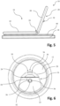
- Fig.1 shows a schematic perspective view of a resealable can lid 10 for a can, for example a beverage can, from above.
- the can lid has a lid surface 12 which, when attached to a can body, closes off the top of the can.
- a vertical direction of the can lid 10 can be defined by an upright can.
- the top of the respective parts of the can lid are defined with respect to a side facing away from the interior of the can.
- the respective undersides face the interior.
- the terms "top” and “bottom” or “top side” and “bottom side” refer to the usual arrangement of the lid on a can.
- the can lids according to the invention can also be aligned differently or attached to a can if required.
- the can lid 10 is a round flat body and has a radially outer circumferential bead 13 (see e.g. Fig.2 ) for reinforcement. On its outer peripheral edge, the lid panel 12 can be flanged to the can body to connect it and thus produce the closed can.
- the lid panel 12 can have external dimensions and materials that correspond to a conventional lid panel for drinks cans.
- the lid panel 12 is made of a metallic material such as tinplate or aluminum sheet, for example, and was produced in a deep-drawing and/or punching process.
- the lid panel 12 is additionally coated with plastic on its top and bottom.
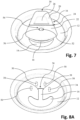
- the lid surface 12 also has a pouring opening 14, which, for example, Fig.7
- the pouring opening 14 is at least partially oval.
- the can lid 10 has an actuating element 16, which is arranged on the top side of the lid surface 12.
- the can lid 10 has a closure element 18, which is arranged on the bottom side of the lid surface 12.
- the closure element 18 is, for example, in Fig.3
- the closure element 18 can be moved translationally and essentially free of rotation between a closed position and an open position, whereby these positions correspond to a closed or opened can lid 10.
- the closure element 18 In its closed position, the closure element 18 closes the pouring opening 14 in a gas- and liquid-tight manner.
- the closure element 18 covers the pouring opening 14 in the closed position and thus seals it from the inside against the interior of the can.
- the closure element 18 In its open position, the closure element 18 at least partially exposes the pouring opening 14.
- the actuating element 16 is connected to the closure element 18. By moving the actuating element 16, the closure element 18 can therefore be moved, in particular guided, between the closed position and the open position.
- One type of guide is described below as an example.
- the connection is preferably designed as a riveted connection, which is shown here and will be described in more detail below.
- the connection can be a welded connection, for example.
- the actuating element 16 has a handle section 20 and a fastening section 22.
- the actuating element 16 is formed in one piece from a sheet metal.
- the handle section 20 and the fastening section 22 are connected via a film hinge 24 as a joint.
- the Film hinge 24 allows rotation of the handle portion 20 relative to the fastening portion 22 about its longitudinal axis.
- the film hinge 24 is formed by a local weakening in the actuating element, for example by a notch.
- Fig.2 is shown in a schematic perspective view how the handle portion 20 is partially removed from its initial position, shown in Fig.1 , has been rotated upwards relative to the fastening section 22.
- the handle section 20 has a region 30 of reduced thickness at its end facing away from the fastening section 22. This makes it particularly easy to lift the handle section 20 from its starting position, for example with a fingernail.
- the handle portion In the starting position ( Fig.1 ), the handle portion extends substantially parallel to the cover surface 12 and lies substantially flat thereon.
- Fig.4 illustrates in a schematic perspective view an actuating position of the handle section 20.
- the handle section 20 is rotated far upwards, for example at least 60° or at least 80° relative to a plane defined by the fastening section 22 and/or the cover surface.
- the handle section 20 can be gripped particularly easily to move the closure element 18, for example with two fingers.
- the handle section 20 also has a recess 26 on its upper side (see Fig.1 ), which can provide additional support for a finger (especially the thumb) when adjusting.
- the actuating element 16 has a locking section 28 on the underside.
- This locking section is also formed from a sheet metal in one piece with the rest of the actuating element 16.
- the sheet metal can be bent (in particular folded) in the area 30 to form a second layer of material on the actuating element 16.
- the second layer of material, which forms the locking section 28, can also be regarded as part of the handle section 20.
- the two layers of material can reinforce the handle section 20 so that higher actuation forces are possible without damage.
- the thin edge area 30 can also be formed cost-effectively in a single production step.
- the locking section 28 is held in other partial areas 29 by a rounded edge of the handle section 20, which also avoids a sharp outer edge.
- the locking section 28 has a locking element 32 which protrudes from the underside.
- the locking element 32 is designed as a hook, which is particularly well visible in the side view of Fig.3 can be seen.
- the locking element 32 In the starting position, the locking element 32 extends into a corresponding recess 34 of the closure element 18, whereby the handle section 20 can lie flat and the hook can grip behind the lid panel 12. The handle section 20 is thus locked in the starting position.
- the locking element 32 can plastically deform and thus detach from the lid surface 12. This can provide an authenticity feature, which can be used to identify that the can has been opened for the first time. After the can has been lifted for the first time, the plastic deformation can prevent it from being locked again. The release of the locking element 32 can cause a noise, which is also perceptible to the user as a signal.
- the locking element 32 can only deform essentially elastically when the can is opened for the first time. This allows the locking element 32 to lock again to the lid surface when the handle section 20 is adjusted back, for example in the manner of a latching and/or a snap connection. This can provide transport security even after the can has been opened for the first time. This renewed locking can also cause a noise, which signals to the user that it has been locked again.
- the actuating element 16 is preferably designed such that it deforms after the handle section 20 is moved from its initial position for the first time. This can prevent the handle section 20 from being moved back to the initial position and/or indicate that it has been opened for the first time.
- the film hinge 24 can deform and/or tear at an outer edge in such a way that the handle section 20 no longer remains in the initial position and/or the deformation and/or the tear is visible to a user.
- the handle section can only be moved to an intermediate position, as in Fig.2 and 3 shown, after initial opening.
- a backward bending of the handle section 20 is also prevented by the fact that a downward rotation beyond the lid surface 12 would be necessary to reverse the plastic deformation, but is blocked by the lid surface 12 due to the fastening of the actuating element 16 thereto.
- the locking section 28 does not extend to the Film hinge 24. This can promote a corresponding deformation as an authenticity feature.
- the starting position can correspond to a stowed position of the handle section 20 before it is opened for the first time.
- Fig. 8A illustrates in a schematic plan view the lid surface 12, which is shown there without the actuating element 16 and the closing element 18.
- the lid surface 12 has an additional passage area to the pouring opening 14 in the form of an elongated guide slot 34.
- the connection between the actuating element 16 and the closing element 18 is arranged in the guide slot 34 and thus the displacement of the closing element 18 between the closed position and the open position is guided.
- the locking element 32 is also arranged in the guide slot 34 before the can is opened for the first time.
- the pouring opening 14 and the guide slot 34 are formed as a common through-opening in the lid surface 12. This means that they can be manufactured together at low cost, for example in a stamping process.
- the can lid 12 has two relief notches 38 which extend essentially transversely to the longitudinal extent of the guide slot 34. As a result, the corners in the end region 36 of the guide slot 34 are rounded, which counteracts tearing due to internal pressure in the can.
- the lid surface 12 can also have a design which can cause pressure equalization when the can is opened.
- a notch 40 can optionally be arranged adjacent to the pouring opening 14 in an area facing away from the direction of movement of the actuating element 16 from the closed position to the open position. This notch can form a thin channel between the interior and the exterior of the can before the pouring opening 14 is actually released. An overpressure in the interior of the can can thus produce a clear hissing noise, which signals this overpressure to the user and thus the freshness of the drink.
- an additional through opening 42 with a small diameter can optionally be arranged in this area in order to also open a channel with a small cross-section before the pouring opening 14 is actually opened.
- the through opening 42 can also be referred to as a pressure equalization opening. This can also be used to acoustically signal the excess pressure and thus the freshness of the can contents to a user.
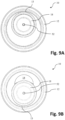
- Fig. 9A the can lid 10 with the closure element 18 in the closed position is shown in a bottom view.
- the closure element 18 covers the pouring opening 14.
- Fig. 9B the closure element 18 is shown in the open position.
- the pouring opening 14 is largely exposed.
- the pouring opening 14 is exposed in such a way that a drinking straw (not shown) can be guided directly through the pouring opening 14 into the can.
- Fig.10 illustrates the can lid 10 in another top view.
- Fig. 11 illustrates the can lid 10 according to Fig.10 in a schematic side view.
- Fig. 12 corresponds to a sectional view along the line BB, as in Fig.10 marked.
- a seal 44 is arranged on the closure element 18 in a groove on the top facing the cover surface 12.
- the seal 44 is also in Fig.3 and 5
- the closure element 18 is connected to the actuating element 16 in such a way that the seal 44 is pressed against the cover surface 12 on the underside and thus seals the pouring opening 14 in the closed position.
- the actuating element 16 rests only with its curved edge 46 on the top of the lid surface 12 and can thus be slightly pre-tensioned.
- the actuating element can be essentially straight in the unconnected state and bent towards the closure element 18 when connected to it.
- the closure element, in particular its underside can be domed in the unconnected state, in particular concavely domed.
- the closure element 18 has an area 49 that rests against the cover mirror 12. This can support the actuating element 18, in particular the film hinge 24, as well as the cover mirror 12 in this area when the handle section 20 is pivoted. This can prevent overloading and unwanted deformation of the cover mirror 12. Alternatively or additionally, the closure element 18 can rest against the cover mirror along a central area 47.
- the closure element 18 has respective recesses 48. In the open position, these recesses 48 can provide an additional air channel between the interior of the can and the surroundings. Air can flow back through the air channel during pouring to enable quick and even pouring.
- An inlet of the air channel can be formed, for example, by an opening between the actuating element 16 and the closure element 18. In the closed position, this opening is blocked by the lid surface 12. By moving this inlet into the area of the pouring opening 14, a gap is created between the actuating element 16 and the closure element 18 through which air can flow.
- An opening can be opened as an outlet for the air duct by deflecting the closure element 18 on the circumferential bead 13 of the lid surface 12 and thus spacing it from the underside of the lid surface.
- the closure element 18 and/or the lid surface 12 can deform elastically in order to also open up a gap.
- the closure element can rotate downwards slightly in an end region.
- a depression 50 in the form of an embossing can be arranged in the lid surface 12 in this region in the direction of the interior of the can downwards (not shown), which can also cause the closure element 18 to deflect from the lid surface 12 in certain regions.
- one or more bulges 50 can be formed in the top of the lid surface 12, whereby at least one passage for the air channel can be opened in the open position.
- the lid surface 12 is particularly resistant to deformation due to internal can pressure.
- Fig. 8A Four bulges 50 are illustrated by dashed lines as examples. These can be produced as embossings.
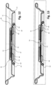
- Fig. 13 shows the sectional view of the can lid 10 along line CC, Fig. 14 along line AA.
- the connection of the actuating element 16 to the closure element 18 can be seen particularly well.
- the connection does not penetrate the closure element 18.
- the closure element 18 has a rivet nipple 52 which protrudes from the closure element 18 towards the top and is at least partially arranged in the guide slot 34.
- the rivet nipple 52 extends through a rivet opening in the actuating element 16 to its top and is clamped thereto by riveting.
- the actuating element 16 engages behind the rivet nipple 52 at least partially.
- the rivet opening of the actuating element 16 is arranged in a recess 54 of the actuating element 16 formed towards the underside.
- the recess 54 can also be seen as a projection which preferably projects towards the underside of the lid panel 12.
- the recess 54 extends into the guide slot 34 and can be supported on the edge of the guide slot 34 formed by the lid panel 12 to guide the adjustment movement between the closed position and the open position.
- the recess 54 allows the rivet connection to have a low overall height and thus also the can lid 10.
- the rivet connection only needs to have a slightly greater height than a conventional riveting of a lid panel to a metal tab of a conventional can which is not resealable. This means that conventional machines and processes can also be used for the can lid 10.
- the rivet connection does not have to have a thickness of the material of the cover plate 12, the actuating element 16 and the closure element 18, but only of the actuating element 16 and the closure element 18.
- the recess 54 can also provide an anti-twisting device.
- the recess 54 has two essentially flat surfaces 56, which, among other things, Fig.10 to recognize
- the flat surfaces 56 extend, for example, essentially parallel to the edge of the cover surface 12, which delimits the guide slot 34.
- the flat surfaces 56 can be supported on this edge when the actuating element 16 is displaced along the guide slot 34 and thus prevent an undesired rotation of the actuating element 16.
- Fig. 15 shows a particularly advantageous cross-sectional design of the seal 44 in a sectional view. It can be seen that the seal 44 is at least partially accommodated in a groove 58 of the closure element 18.
- the seal 44 has a sealing lip 60 on the top, with which it contacts the lid surface 12 on the underside.
- the sealing lip 60 is preferably inclined.
- the sealing lip 60 can extend radially inwards from the groove 58 and/or be inclined radially inwards. Below and radially inside the sealing lip 60, the latter has an undercut 62. If the sealing lip 60 is pressed more strongly, for example due to increased internal can pressure, the sealing lip can move into this free space. This allows different pressures to be compensated without damaging the seal 44.
- an actuating force can vary less with the internal can pressure due to friction between the seal 44 and the lid surface 12.
- a free space 64 is preferably provided radially on the outside in the groove 58, which is not occupied by the seal 44. This enables a compensating movement of the sealing lip 60 during a movement in the image plane of Fig. 15 to the left, whereby the sealing lip 60 can be protected from damage during repeated opening and closing of the can lid 10.
- the seal 44 can be clamped in the groove 58 by means of a folded edge 45 and/or that the groove can be formed by such a fold.
- an outer edge of the closure element 18 is sealed by the seal 44.
- This edge can, for example, not be covered with plastic In this way, the entry of metal particles into the can contents and/or corrosion of this edge can be prevented, in particular by preventing contact with the can contents.
- the seal 44 is kept safe and simple.
- Fig. 16 clarifies once again the shape of the closure element 18 in an exploded view before connection with the seal 44.
- the rivet nipple 52 can be seen, which is surrounded by the central area 47.
- the central area is at least partially or, as in Fig. 16 shown, completely surrounded by the recess 48, which also forms the air channel.
- a raised area 49 is provided all the way around, which can rest against the cover surface 12 to support the hinge 24.
- the closure element 18 is preferably rotationally symmetrical to facilitate manufacture.
- Figs. 17 and 18 show further optional features and configurations of the cover mirror 12, which can be used in combination with each of the cover mirrors 12 described above.
- the cover mirror 12 has at least one first recess 50A or several recesses 50A, which can form a second open end of the air channel 48 during the opening of the closure element 20 and/or in its open position, as already described above.
- the at least one first recess 50A is preferably arranged such that in the closed position of the closure element 18 it is located within the seal 49 (see Fig. 16 and 19 ) is arranged.
- the at least one first recess 50A is preferably arranged such that it is in the closed position of the closure element 18 (in Figs. 17 and 18 not shown) and/or covered by the actuating element 16, preferably completely.
- pressure equalization can be achieved, in particular an initial Pressure equalization when opening the closure element 18.
- the at least one first recess 50A can be arranged such that it is completely overlapped by the closure element 18 in the open position and/or is arranged completely within the seal 44.
- the cover panel 12 can have at least one second recess 50B. This is preferably arranged such that it is not covered by the closure element 18 in the closed position and/or is not arranged within the seal 44 in the closed position, not even partially.
- the at least one second recess 50B is preferably not covered by the actuating element 16 in the closed position.
- the at least one second recess is preferably partially (in particular only partially) overlapped by the closure element 20 and/or the seal 50 and/or the actuating element 16.
- the second recess 50B can thus provide an alternative open second end for the air channel 48 in the closed position.
- the use of different recesses 50A, 50B makes it possible to selectively adjust the air flow through the air channel 48.
- the at least one first recess can be dimensioned such that a hissing sound occurs when it is opened.
- the at least one second recess 50B can, for example, be dimensioned such that gurgling is prevented during pouring, in particular when the closure element 18 is completely opened.
- the second recess 50B can be designed, for example, as one or more recesses 50B which are located in the direction of displacement of the actuating element 16 behind the operating element 30 (see Fig. 17 ) and/or next to the actuating element 16 (see Fig. 18 ).
- the at least one first recess 50A and/or the at least one second recess 50B can protrude upwards or downwards.
- the at least one first recess 50A and/or the at least one second recess 50B can in particular be formed as an embossing in the cover surface 12.
- the cover surface 12 can further comprise one or more (in particular two) third recesses 51. These can be provided with one or more corresponding projections 73 on the upper side of the closure element 18 cooperate (see Fig. 21) to provide a longitudinal guide and/or anti-twist device for the closure element 18.
- the recess 51 preferably projects upwards. It can be designed as an embossing in the cover surface 12.
- Fig. 19 shows a further embodiment of the closure element 18 to illustrate some further optional features.
- the closure element here has in particular a first adjacent region 49A and a second adjacent region 49B, both of which protrude upwards from the closure element 18. These serve to support the hinge.
- the closure element can also have a recess for receiving the locking element, which in the embodiment shown is provided as a recess 74 in addition to the air channel 48.
- the closure element 18 does not have to be rotationally symmetrical.
Landscapes
- Engineering & Computer Science (AREA)
- Mechanical Engineering (AREA)
- Closures For Containers (AREA)
- Containers Opened By Tearing Frangible Portions (AREA)
- Rigid Containers With Two Or More Constituent Elements (AREA)
- Closing Of Containers (AREA)
Claims (16)
- Couvercle de canette (10) pour une canette, réalisé de préférence en tant que canette pour boisson et/ou en tant que contenant de conservation pour une marchandise en vrac, avec :au moins une surface de couvercle (12), laquelle est réalisée pour délimiter un côté supérieur de la canette, de préférence en bordant un bord périphérique extérieur de la surface de couvercle (12) avec une paroi latérale de la canette, dans lequel la surface de couvercle (12) présente au moins une ouverture de déversement (14), par laquelle une substance se trouvant dans la canette peut être déversée ;un élément d'actionnement (16), lequel est disposé sur un côté supérieur de la surface de couvercle (12), laquelle est opposée à un espace intérieur de la canette lorsque le couvercle de canette (10) est installé dessus ; etun élément de fermeture (18), lequel est agencé sur un côté inférieur de la surface de couvercle (12), lequel est tourné vers un espace intérieur de la canette lorsque le couvercle de canette (10) est installé dessus, dans lequel l'élément de fermeture (18) peut être coulissé de manière guidée sensiblement par translation le long de la surface de couvercle (12) au moyen de l'élément d'actionnement (16) entre une position fermée, dans laquelle l'élément de fermeture (18) ferme l'ouverture de déversement (14) de manière étanche aux fluides et/ou de manière étanche aux gaz, et une position ouverte, dans laquelle l'ouverture de déversement (14) est dégagée au moins en partie ;dans lequel l'élément de fermeture (18) et l'élément d'actionnement (16) sont formés à partir d'un matériau métallique, de préférence à partir d'un matériau en aluminium ou en fer-blanc ; etdans lequel l'élément de fermeture (18) et l'élément d'actionnement (16) sont fixés l'un sur l'autre au moyen d'une liaison, dans lequel la liaison se déplace dans la surface de couvercle (12) le long d'une entaille de guidage (34) lors du coulissement de l'élément de fermeture (18) depuis la position fermée dans la position ouverte ;caractérisé en ce quela distance entre l'élément d'actionnement (16) et l'élément de fermeture (18) est fixe et/ou est invariable dans la zone de la liaison ;de préférence dans lequel la liaison est une liaison par rivetage ou une liaison par soudage.
- Couvercle de canette (10) selon la revendication 1,
dans lequel la liaison réalisée en tant que liaison par rivetage est formée par un mamelon à rivet (52) formé dans l'élément de fermeture (18) ou l'élément d'actionnement (16), lequel est disposé dans une ouverture à rivet correspondante de l'autre des deux éléments (16, 18). - Couvercle de canette (10) selon la revendication 2,dans lequel l'ouverture à rivet s'étend à travers une partie faisant saillie (54), de préférence à travers une partie faisant saillie (54), faisant saillie en direction du côté inférieur de la surface de couvercle (12), de l'élément d'actionnement (16) ;dans lequel la partie faisant saillie (54) s'étend de préférence au moins en partie à travers l'entaille de guidage (34) dans la position ouverte et/ou dans la position fermée.
- Couvercle de canette (10) selon l'une quelconque des revendications précédentes, dans lequel au moins une face plane (56) est réalisée sur la liaison dans une zone, qui s'étend à travers l'entaille de guidage (34) ;
dans lequel l'au moins une face plane (56) est tournée vers un bord, délimitant l'entaille de guidage (34), de la surface de couvercle (12). - Couvercle de canette (10) selon l'une quelconque des revendications précédentes,dans lequel le couvercle de canette (10) présente au moins un joint d'étanchéité (44), lequel est agencé entre l'élément de fermeture (18) et la surface de couvercle (12) au moins dans la position fermée de l'élément de fermeture (18) ;dans lequel le joint d'étanchéité (44) est logé de préférence au moins en partie dans une rainure (58), qui est réalisée sur un côté supérieur de l'élément de fermeture (18) ;
et/oudans lequel le joint d'étanchéité (44) est bloqué sur l'élément de fermeture (18) de préférence au moyen d'un bord extérieur de l'élément de fermeture (18), dans lequel le bord extérieur est cintré dans le joint d'étanchéité (44) et/ou par-dessus une section du joint d'étanchéité (44). - Couvercle de canette (10) selon la revendication 5,dans lequel le joint d'étanchéité (44) présente une contre-dépouille (62) ;
et/ouune section transversale de la zone partielle, logée dans la rainure (58), du joint d'étanchéité (44) est plus petite qu'une section transversale de la rainure (58). - Couvercle de canette (10) selon l'une quelconque des revendications précédentes, dans lequel la surface de couvercle (12) et/ou l'élément de fermeture (18) présentent une encoche (40) ou une marque dans une zone partielle, laquelle est disposée de manière adjacente à une zone partielle de l'ouverture de déversement (14), laquelle est dégagée d'abord lors de l'ajustement de l'élément de fermeture (18) depuis la position fermée dans la position ouverte, ou délimite ladite zone partielle.
- Couvercle de canette (10) selon l'une quelconque des revendications précédentes, dans lequel la surface de couvercle (12) présente en outre une ouverture de compensation de pression (42), dans lequel la surface de section transversale de l'ouverture de compensation de pression (42) est inférieure à la surface de section transversale de l'ouverture de déversement (14) ;dans lequel l'ouverture de compensation de pression (42) est fermée de manière étanche aux fluides et/ou de manière étanche aux gaz par l'élément de fermeture (18) dans la position fermée et est dégagée au moins en partie dans la position ouverte ;dans lequel l'ouverture de compensation de pression (42) est agencée de telle manière que celle-ci est dégagée devant l'ouverture de déversement (14) lors de l'ajustement de l'élément de fermeture (18) depuis la position fermée dans la position ouverte.
- Couvercle de canette (10) selon l'une quelconque des revendications précédentes, dans lequel est formé, dans la position ouverte, entre l'élément de fermeture (18) et la surface de couvercle (12), un canal d'air (48), dont la première extrémité débouche sur le côté supérieur de la surface de couvercle (12) et/ou sur une zone d'extrémité, opposée au bord de surface de couvercle extérieur, de l'ouverture de déversement (14) et dont la seconde extrémité débouche sur un côté inférieur de la surface de couvercle (12) sur une zone d'extrémité, opposée à l'ouverture de déversement (14), de l'élément de fermeture (18).
- Couvercle de canette (10) selon l'une quelconque des revendications précédentes, dans lequel l'élément d'actionnement (16) présente au moins une section de fixation (22), dans laquelle la liaison est réalisée avec l'élément de fermeture (18), et une section de préhension (20) reliée à celle-ci, laquelle est réalisée pour la préhension aux fins de l'ajustement entre la position ouverte et la position fermée ;dans lequel la section de préhension (20) peut être pivotée de préférence entre une position de rangement, dans laquelle la section de préhension (20) est disposée de manière sensiblement parallèle par rapport à la surface de couvercle (12) et/ou à la section de fixation (22), et une position d'actionnement, dans laquelle la section de préhension (20) peut être saisie pour l'ajustement entre la position ouverte et la position fermée ; etdans lequel la section de fixation (22) et la section de préhension (20) sont reliées au moyen d'une articulation, en particulier au moyen d'une charnière à film (24), dont l'axe d'articulation s'étend de manière transversale par rapport à un axe longitudinal de l'entaille de guidage (34), dans lequel la section de préhension (20) est réalisée pour être pivotée autour de l'axe d'articulation par rapport à la section de fixation (22) pour l'ajustement entre la position de rangement et la position d'actionnement.
- Couvercle de canette (10) selon la revendication 10,dans lequel la section de préhension (20) a une position de départ, laquelle correspond de préférence à la position de rangement ;dans lequel l'élément d'actionnement (16) est réalisé de telle sorte que la section de préhension (20) peut être ramenée tout en ne restant plus dans la position de départ après un premier ajustement depuis la position de départ ;
et/oudans lequel l'élément d'actionnement (16) est réalisé de telle sorte qu'il se déforme plastiquement lors d'un premier ajustement de la section de préhension (20) depuis la position de départ, en particulier durablement et/ou tout en restant identifiable de manière optique. - Couvercle de canette (10) selon l'une quelconque des revendications précédentes, dans lequel l'élément d'actionnement (16) présente une section d'arrêt (28), au moyen de laquelle l'élément d'actionnement (16) est arrêté dans la position fermée sur la surface de couvercle (12) avant un premier ajustement depuis la position fermée dans la position ouverte ;
dans lequel la section d'arrêt (28) présente de préférence un élément d'arrêt (32) faisant saillie vers le bas depuis le côté inférieur de l'élément d'actionnement (16) ; dans lequel l'élément d'arrêt (32) est réalisé de préférence en tant que crochet. - Canette, de préférence réalisée en tant que canette pour boisson et/ou en tant que contenant de conservation pour une marchandise en vrac, présentant au moins un couvercle de canette (10) selon l'une quelconque des revendications précédentes.
- Procédé de fabrication d'un couvercle de canette (10) selon l'une quelconque des revendications 1 à 12, pour une canette, de préférence réalisée en tant que canette pour boisson et/ou en tant que contenant de conservation pour une marchandise en vrac, caractérisé par des étapes suivantes :- de fourniture d'une surface de couvercle (12), laquelle est réalisée pour délimiter un côté supérieur de la canette, en particulier en bordant un bord périphérique extérieur de la surface de couvercle (12) avec une paroi latérale de la canette, dans lequel la surface de couvercle (12) présente au moins une ouverture de déversement (14), par laquelle une substance se trouvant dans la canette peut être déversée, et une entaille de guidage (34) ;- de fourniture d'un élément d'actionnement (16) et d'un élément de fermeture (18) formé à partir d'un matériau métallique, de préférence à partir d'un matériau en aluminium ou de fer-blanc ;- d'agencement de l'élément de fermeture (18) sur un côté inférieur de la surface de couvercle (12), lequel est tourné vers un espace intérieur de la canette lorsque le couvercle de canette (10) est installé dessus ;- d'agencement de l'élément d'actionnement (16) sur un côté supérieur de la surface de couvercle (12), lequel est opposé à un espace intérieur de la canette lorsque le couvercle de canette (10) est installé dessus ;- de fixation de l'élément de fermeture (18) et de l'élément d'actionnement (16) au moyen d'une liaison l'un à l'autre, dans lequel la liaison peut être déplacée le long de l'entaille de guidage (34) ;dans lequel l'élément de fermeture (18) peut être coulissé de manière guidée sensiblement par translation le long de la surface de couvercle (12) au moyen de l'élément d'actionnement (16) entre une position fermée, dans laquelle l'élément de fermeture (18) ferme l'ouverture de déversement (14) de manière étanche aux fluides et/ou de manière étanche aux gaz, et une position ouverte, dans laquelle l'élément de fermeture (18) dégage au moins en partie l'ouverture de déversement (14) ;caractérisé en ce quela distance entre l'élément d'actionnement (16) et l'élément de fermeture (18) est fixe et/ou est invariable dans la zone de la liaison ;de préférence dans lequel la liaison est une liaison par rivetage ou une liaison par soudage.
- Procédé selon la revendication 14, dans lequel l'élément d'actionnement (16) présente une section d'arrêt (28), au moyen de laquelle l'élément d'actionnement (16) est arrêté sur la surface de couvercle (12) dans la position fermée avant un premier ajustement depuis une position fermée dans la position ouverte.
- Procédé selon la revendication 15, présentant en outre les étapes suivantes :- de formage d'une zone faisant saillie côté inférieur dans la section d'arrêt (28), en particulier au moyen d'estampage et de cintrage ;- d'agencement de l'élément d'actionnement (16) côté supérieur sur la surface de couvercle (12) de telle manière que la zone faisant saillie dépasse par l'entaille de guidage (34), dans lequel l'élément d'actionnement (16) est disposé de préférence dans la position fermée ; et- de cintrage par la suite d'une zone partielle de la zone faisant saillie, en particulier au moyen d'un coulisseau pour former de préférence un crochet (32).
Priority Applications (1)
| Application Number | Priority Date | Filing Date | Title |
|---|---|---|---|
| EP24192760.7A EP4458718A3 (fr) | 2018-12-17 | 2019-12-16 | Fermeture de boîte à boisson, boîte à boisson et méthode de fabrication d'une fermeture de boîte à boisson |
Applications Claiming Priority (2)
| Application Number | Priority Date | Filing Date | Title |
|---|---|---|---|
| EP18212937.9A EP3670373B1 (fr) | 2018-12-17 | 2018-12-17 | Système de fermeture pour canettes de boisson |
| PCT/EP2019/085335 WO2020127037A1 (fr) | 2018-12-17 | 2019-12-16 | Couvercle de boîte-boisson, boîte-boisson et procédé de fabrication d'un couvercle de boîte-boisson |
Related Child Applications (1)
| Application Number | Title | Priority Date | Filing Date |
|---|---|---|---|
| EP24192760.7A Division EP4458718A3 (fr) | 2018-12-17 | 2019-12-16 | Fermeture de boîte à boisson, boîte à boisson et méthode de fabrication d'une fermeture de boîte à boisson |
Publications (2)
| Publication Number | Publication Date |
|---|---|
| EP3898436A1 EP3898436A1 (fr) | 2021-10-27 |
| EP3898436B1 true EP3898436B1 (fr) | 2024-08-14 |
Family
ID=64744376
Family Applications (5)
| Application Number | Title | Priority Date | Filing Date |
|---|---|---|---|
| EP18212937.9A Active EP3670373B1 (fr) | 2018-12-17 | 2018-12-17 | Système de fermeture pour canettes de boisson |
| EP19818102.6A Pending EP3898437A1 (fr) | 2018-12-17 | 2019-12-16 | Système de fermeture destiné à des canettes de boisson |
| EP19818097.8A Active EP3898436B1 (fr) | 2018-12-17 | 2019-12-16 | Fermeture de boîte à boisson, boîte à boisson et méthode de fabrication d'une fermeture de boîte à boisson |
| EP24192760.7A Pending EP4458718A3 (fr) | 2018-12-17 | 2019-12-16 | Fermeture de boîte à boisson, boîte à boisson et méthode de fabrication d'une fermeture de boîte à boisson |
| EP19817358.5A Active EP3898435B1 (fr) | 2018-12-17 | 2019-12-16 | Couvercle de canette et canette |
Family Applications Before (2)
| Application Number | Title | Priority Date | Filing Date |
|---|---|---|---|
| EP18212937.9A Active EP3670373B1 (fr) | 2018-12-17 | 2018-12-17 | Système de fermeture pour canettes de boisson |
| EP19818102.6A Pending EP3898437A1 (fr) | 2018-12-17 | 2019-12-16 | Système de fermeture destiné à des canettes de boisson |
Family Applications After (2)
| Application Number | Title | Priority Date | Filing Date |
|---|---|---|---|
| EP24192760.7A Pending EP4458718A3 (fr) | 2018-12-17 | 2019-12-16 | Fermeture de boîte à boisson, boîte à boisson et méthode de fabrication d'une fermeture de boîte à boisson |
| EP19817358.5A Active EP3898435B1 (fr) | 2018-12-17 | 2019-12-16 | Couvercle de canette et canette |
Country Status (13)
| Country | Link |
|---|---|
| US (4) | US11884449B2 (fr) |
| EP (5) | EP3670373B1 (fr) |
| JP (3) | JP7538542B2 (fr) |
| KR (2) | KR102876221B1 (fr) |
| CN (4) | CN119660113A (fr) |
| AU (4) | AU2019406290B2 (fr) |
| CA (2) | CA3123736C (fr) |
| ES (1) | ES2874333T3 (fr) |
| HR (1) | HRP20211171T1 (fr) |
| MX (2) | MX2021007228A (fr) |
| RS (1) | RS61973B1 (fr) |
| RU (1) | RU2766906C1 (fr) |
| WO (3) | WO2020126969A1 (fr) |
Families Citing this family (13)
| Publication number | Priority date | Publication date | Assignee | Title |
|---|---|---|---|---|
| CN113353465B (zh) | 2016-03-14 | 2022-08-30 | 野醍冷却器有限责任公司 | 绝热容器和形成绝热容器的方法 |
| EP4268682A3 (fr) * | 2018-10-23 | 2023-12-27 | YETI Coolers, LLC | Fermeture et couvercle et procédé de formation de fermeture et de couvercle |
| RS61973B1 (sr) | 2018-12-17 | 2021-07-30 | Re Lid Eng Ag | Sistem za zatvaranje konzerve za piće |
| USD964102S1 (en) | 2019-10-09 | 2022-09-20 | Yeti Coolers, Llc | Tumbler |
| USD982973S1 (en) | 2019-10-09 | 2023-04-11 | Yeti Coolers, Llc | Tumbler |
| USD982982S1 (en) | 2020-10-01 | 2023-04-11 | Yeti Coolers, Llc | Tumbler |
| USD977912S1 (en) | 2020-10-01 | 2023-02-14 | Yeti Coolers, Llc | Tumbler |
| PL242647B1 (pl) * | 2021-02-10 | 2023-04-03 | Reend Spolka Z Ograniczona Odpowiedzialnoscia | Pokrywa pojemnika |
| DE102022202042A1 (de) | 2022-02-28 | 2023-08-31 | Gert Löwe | Gefäßdeckelanordnung für ein Trinkgefäß |
| DE102023107869A1 (de) * | 2023-03-28 | 2024-10-02 | Top Cap Holding Gmbh | Dosendeckel |
| EP4588818A1 (fr) | 2024-01-19 | 2025-07-23 | RE-LID Engineering AG | Système de fermeture, récipient de boisson et procédé de fabrication d'un système de fermeture pour récipient de boisson |
| USD1100658S1 (en) * | 2024-06-04 | 2025-11-04 | Re-Lid Engineering Ag | Re-sealable can lid |
| DE102024116754A1 (de) * | 2024-06-14 | 2025-12-18 | Ardagh Metal Packaging Europe Gmbh | Deckelelement für einen Getränkebehälter und Verschlussanordnung für einen Getränkebehälter |
Family Cites Families (147)
| Publication number | Priority date | Publication date | Assignee | Title |
|---|---|---|---|---|
| US2302972A (en) * | 1941-01-22 | 1942-11-24 | Virgil B Nuckols | Dispenser closure |
| US2429984A (en) * | 1944-08-23 | 1947-11-04 | American Can Co | Valve closed container |
| US3250425A (en) * | 1964-02-17 | 1966-05-10 | Continental Can Co | Rotatable pull tab to break scored tear strip |
| US3259265A (en) * | 1964-02-27 | 1966-07-05 | Crown Cork & Seal Co | Reseal for tab opening cans |
| US3363798A (en) | 1965-10-11 | 1968-01-16 | Panagiotis M. Garangiotis | Sliding closure for a pressurized beverage container |
| US3447724A (en) | 1967-01-10 | 1969-06-03 | Earl W Fiddyment | Pour spout and vent construction |
| US3705671A (en) | 1970-08-05 | 1972-12-12 | United States Steel Corp | Can end with bonded seal slide |
| US3705670A (en) * | 1970-08-05 | 1972-12-12 | United States Steel Corp | Can end with bonded seal slide |
| US3708091A (en) | 1970-08-05 | 1973-01-02 | Steel Corp | Can end with bonded seal slide |
| US3717276A (en) | 1971-02-12 | 1973-02-20 | Owens Illinois Inc | Vented closure |
| US3952914A (en) | 1975-02-24 | 1976-04-27 | Vogt Kuno J | Re-sealable container lid |
| US4023703A (en) | 1975-05-27 | 1977-05-17 | Strobe Carl J | Easy-open container with flange push-in member |
| US4136797A (en) * | 1976-11-15 | 1979-01-30 | Crown Cork & Seal Company, Inc. | Easy-opening can end and method of opening |
| US4077538A (en) * | 1976-08-16 | 1978-03-07 | Waterbury Nelson J | Vendable reclosable beverage container |
| US4078702A (en) * | 1976-10-14 | 1978-03-14 | Pennwalt Corporation | Automatically re-closing a closure difficult for children to open |
| US4170724A (en) * | 1977-01-28 | 1979-10-09 | Waterbury Nelson J | Vendable reclosable beverage container |
| US4127212A (en) * | 1977-01-28 | 1978-11-28 | Waterbury Nelson J | Vendable reclosable beverage container |
| US4099642A (en) * | 1977-12-01 | 1978-07-11 | Dart Industries, Inc. | Drinking receptacle cover and valve assembly |
| US4162742A (en) * | 1978-07-24 | 1979-07-31 | Vogt Kuno J | Easy opening top closure member for a container |
| US4183443A (en) | 1978-08-25 | 1980-01-15 | Billitzer Edward P | Reusable cup cover |
| US4339053A (en) | 1978-09-07 | 1982-07-13 | Tarro Richard E | Container with attached pull tab opener and indicator |
| US4234099A (en) | 1978-09-07 | 1980-11-18 | Tarro Richard E | Container with attached pull tab opening |
| US4171060A (en) | 1978-12-11 | 1979-10-16 | Spil-Les | Covered drinking cup |
| US4190174A (en) * | 1979-01-29 | 1980-02-26 | Thermo-Seal, Inc. | Drinking receptacle cover with a lip operated valve |
| US4215794A (en) | 1979-06-29 | 1980-08-05 | United States Steel Corporation | Tab for easy-open can end |
| GB2073646B (en) * | 1980-03-25 | 1983-12-07 | Metal Box Co Ltd | Moulding plastics onto metal sheets |
| US4361249A (en) * | 1981-02-25 | 1982-11-30 | Tuneski Richard J | Beverage container lid |
| US4506809A (en) | 1982-06-25 | 1985-03-26 | Calmar, Inc. | Dispensing fitment for squeeze bottles |
| US4407424A (en) * | 1982-07-01 | 1983-10-04 | The Continental Group, Inc. | Plastic plug type closure for beverage containers |
| US4673099A (en) | 1982-08-23 | 1987-06-16 | Wells Robert A | Reclosable self-opening can end |
| US4433792A (en) * | 1982-09-29 | 1984-02-28 | George Mandel | Opening and stopper device |
| US4442950A (en) * | 1983-01-24 | 1984-04-17 | Wilson Thomas P | Opening and closing means for a container top |
| US4463866A (en) * | 1983-03-11 | 1984-08-07 | George Mandel | Contamination protection member for opening and resealing device |
| GB8404320D0 (en) | 1984-02-18 | 1984-03-21 | Metal Box Plc | Closure for container |
| EP0161754B1 (fr) | 1984-05-08 | 1989-05-24 | MB GROUP plc | Fermetures pour récipients |
| US4524879A (en) * | 1984-06-18 | 1985-06-25 | Van Dorn Company | Can end pour spout and pull tab construction |
| US4541541A (en) * | 1984-10-09 | 1985-09-17 | Weatherchem Corporation | Tamper-resistant closure for dispensers |
| US4605141A (en) * | 1985-03-01 | 1986-08-12 | Duksoo Won | Opening means having hold down means |
| US4580692A (en) * | 1985-05-29 | 1986-04-08 | Aluminum Company Of America | Container sealing cap |
| US4747511A (en) * | 1986-07-10 | 1988-05-31 | Sun Coast Plastics, Inc. | Plug-type openers for plastic can ends |
| US4681238A (en) * | 1986-10-03 | 1987-07-21 | Sanchez Ruben G | Re-closure device for pop top containers |
| US4711372A (en) | 1987-02-02 | 1987-12-08 | Sunbeam Plastics Corporation | Tamper indicating closure |
| US4865215A (en) * | 1987-06-02 | 1989-09-12 | Wells Robert A | Reclosable self-opening can end |
| JPS6426264U (fr) * | 1987-08-10 | 1989-02-14 | ||
| US4746032A (en) | 1987-08-18 | 1988-05-24 | Meei Huey Tai | Quick-release resealable beverage can cover assembly |
| US4749099A (en) | 1987-11-02 | 1988-06-07 | Arthur Davis | Drink preserver |
| US4784283A (en) * | 1988-01-21 | 1988-11-15 | Paul Cantu | Self-closing beverage can |
| US4877129A (en) * | 1988-06-15 | 1989-10-31 | Wells Robert A | Reclosable self-opening can end |
| US4880137A (en) * | 1988-06-15 | 1989-11-14 | Wells Robert A | Reclosable self-opening can end |
| US4842159A (en) | 1988-08-22 | 1989-06-27 | Heidrich Dennis A | Temporary closure for beverage can |
| US5086941A (en) | 1990-01-25 | 1992-02-11 | Board Of Regents Of The University Of Wisconsin System On Behalf Of University Of Wisconsin - Stout | Dispenser closure assembly |
| US5080249A (en) * | 1990-08-29 | 1992-01-14 | Shock John P | Container and closeable pull tab |
| US5129773A (en) * | 1990-08-29 | 1992-07-14 | Shock John P | Container and closeable pull tab |
| DE9101290U1 (de) * | 1991-02-05 | 1991-04-25 | Mayer, Franz, 8317 Mengkofen | Selbstschließender Verschluß |
| US5285924A (en) * | 1993-02-16 | 1994-02-15 | Morris Kenneth S | Slidable beverage container cover |
| US5555993A (en) * | 1995-02-24 | 1996-09-17 | Borkowski; James T. | Beverage can and pivotal, screen guard opener system |
| US5810189A (en) | 1995-11-22 | 1998-09-22 | Baker; Anthony Leonard | Container seal |
| KR0141618B1 (ko) | 1995-11-28 | 1998-07-15 | 조성호 | 위생성이 개선된 캔뚜껑 |
| US6279769B1 (en) * | 1996-04-30 | 2001-08-28 | Tetra Laval Holdings & Finance S.A. | Device for forming a mouth in a container |
| US6059137A (en) * | 1997-01-24 | 2000-05-09 | Westwood; Peter L. | Reclosable drink can |
| US5938062A (en) | 1997-10-01 | 1999-08-17 | Paramski; Walter P. | Food dispensing package |
| US6050456A (en) * | 1997-11-04 | 2000-04-18 | Progressive Technology Of Wisconsin, Inc. | Screw feeder for proportioning machine |
| AU744397B2 (en) | 1998-06-17 | 2002-02-21 | Akline | Removable case for opening and closing a pressurized can provided with a frangible obturator |
| GB0103404D0 (en) * | 2001-02-12 | 2001-03-28 | Steadman William D | Can opening arrangement |
| US6626314B1 (en) | 2001-03-13 | 2003-09-30 | Rexam Beverage Can Company | Resealable closure for beverage container |
| US6732875B2 (en) | 2001-08-06 | 2004-05-11 | Solo Cup Company | Reclosable container lid |
| GB0226119D0 (en) | 2002-11-08 | 2002-12-18 | Martin Yaffe Internat Ltd | Re-sealable container |
| DE10261232A1 (de) * | 2002-12-20 | 2004-07-22 | Wichelhaus, André | Verschluss für einen Behälter |
| KR100951133B1 (ko) | 2003-01-24 | 2010-04-07 | 도요 세이칸 가부시키가이샤 | 재밀봉성을 구비하고 용이하게 개봉될 수 있는 용기 뚜껑및 그 제법 |
| WO2005110870A1 (fr) | 2003-08-08 | 2005-11-24 | Delport Petrus Jacobus Pieters | Couvercle de recipient a boisson a ouverture de type par rupture |
| NL1024270C2 (nl) | 2003-09-11 | 2005-03-14 | Nicola Perra | Drankhouder, halffabrikaat en werkwijze ter vervaardiging van een drankhouder. |
| US7152753B2 (en) * | 2004-04-23 | 2006-12-26 | Huffman Todd A | Re-sealable can mechanism |
| USD530603S1 (en) | 2004-05-11 | 2006-10-24 | Portola Packaging, Inc. | Container closure having a pull tab |
| US7850037B2 (en) | 2004-10-08 | 2010-12-14 | Dixie Consumer Products Llc | Reclosable lid having a slidable closure panel |
| USD533779S1 (en) | 2004-10-08 | 2006-12-19 | Fort James Corporation | Reclosable cup lid |
| US7874447B2 (en) | 2004-10-08 | 2011-01-25 | Dixie Consumer Products Llc | Reclosable cup lid with sliding member and scalloped track |
| US7845510B2 (en) | 2004-10-08 | 2010-12-07 | Dixie Consumer Products Llc | Reclosable cup lid with sliding closure member |
| KR20060069978A (ko) * | 2004-12-20 | 2006-06-23 | 최상근 | 캔용기 개폐장치 |
| US7275653B2 (en) | 2005-03-10 | 2007-10-02 | International Paper Company | Reclosable container lid |
| US7537134B2 (en) | 2005-06-27 | 2009-05-26 | Lee Richard S | Self-closing fluid container |
| US20070012698A1 (en) | 2005-07-15 | 2007-01-18 | Durdon Terrance N | Cup Lid Having a Sliding Stopper |
| EP1767464A1 (fr) | 2005-09-23 | 2007-03-28 | Crown Packaging Technology, Inc | Dispositif d'étanchéité pour récipient |
| US7513380B2 (en) | 2006-01-20 | 2009-04-07 | Robert Canedo | Self closing container |
| JO2803B1 (en) * | 2006-05-10 | 2014-03-15 | كراون باكيجنج تكنولوجي،انك. | Open Tool |
| DE102007028048A1 (de) * | 2006-06-17 | 2008-06-19 | Horst Heigl | Behälterverschlussvorrichtung |
| DE102006051409A1 (de) | 2006-10-27 | 2008-04-30 | C-A-P Technologies Gmbh | Verpackung für rieselfähige oder fließfähige Produkte |
| US8240498B2 (en) | 2006-10-31 | 2012-08-14 | Crown Packaging Technology, Inc. | Resealable closure |
| US7891517B2 (en) | 2007-01-12 | 2011-02-22 | Samantha Simmons | Apparatus for sealing a beverage can |
| JP4109309B1 (ja) * | 2007-02-05 | 2008-07-02 | 三浦 愛 | プルトップを備えたプルタブ付容器 |
| DE102007007372A1 (de) | 2007-02-12 | 2008-08-14 | C-A-P Technologies Gmbh | Verpackung für rieselfähige oder fließfähige Produkte |
| DE102007049754A1 (de) | 2007-10-16 | 2009-04-23 | C-A-P Technologies Gmbh | Verfahren zum Aufbringen von Deckeln an Verpackungen |
| MX2010005156A (es) * | 2007-11-09 | 2010-10-04 | Crown Packaging Technology Inc | Extremo de lata de bebida resellable y metodos concernientes con el mismo. |
| AT505756B1 (de) | 2008-02-21 | 2009-04-15 | Christian Dipl Ing Bratsch | Deckel eines behalters |
| DE102008011919A1 (de) | 2008-02-29 | 2009-09-03 | Scharf, Andreas | Behältnis für Flüssigkeiten |
| ES2389859T3 (es) | 2008-03-27 | 2012-11-02 | Xolution Gmbh | Cierre para un empaque |
| DE102008031667A1 (de) * | 2008-07-04 | 2010-01-14 | Imv Innovation Marketing Und Vertriebs Gmbh | Wieder verschließbarer Dosendeckel sowie Getränkedose |
| WO2010035914A1 (fr) * | 2008-09-25 | 2010-04-01 | Kangnung-Wonju National University Industry Academy Cooperation Group | Extrémité de boîte refermable |
| USD594329S1 (en) | 2008-10-10 | 2009-06-16 | Stolle Machinery Company, Llc | Tab flange |
| US20100126992A1 (en) | 2008-11-26 | 2010-05-27 | Evan Ira Phillips | Container |
| US8857644B2 (en) | 2008-11-26 | 2014-10-14 | B.E. Inventive, Llc | Container |
| USD615861S1 (en) | 2009-02-03 | 2010-05-18 | Graham Stewart Watts | Can cover |
| AT507950B1 (de) | 2009-02-23 | 2011-07-15 | Xolution Gmbh | Deckel eines behälters |
| AT508082B1 (de) | 2009-04-07 | 2011-01-15 | Xolution Gmbh | Wiederverschliessbarer verschluss eines flüssigkeitsbehälters |
| US8833585B2 (en) | 2009-05-22 | 2014-09-16 | Crown Packaging Technology, Inc. | Resealable beverage can ends |
| AT508717B1 (de) * | 2009-09-07 | 2011-06-15 | Xolution Gmbh | Deckel eines behälters |
| BR112012025469B1 (pt) * | 2010-04-06 | 2020-04-07 | C2C Beteiligungs Gmbh | dispositivo de fecho para recipiente e recipiente com um fecho desta espécie |
| KR101013669B1 (ko) | 2010-05-25 | 2011-02-10 | 서진혁 | 재밀봉 가능한 이지 오픈 엔드 |
| USD632562S1 (en) | 2010-06-29 | 2011-02-15 | Millercoors, Llc | Can end |
| CA2809717C (fr) | 2010-09-01 | 2018-10-23 | E.V.D.S. Bvba | Refermeture d'une canette concue pour des produits alimentaires |
| EP2426058A1 (fr) * | 2010-09-01 | 2012-03-07 | E.V.D.S. Bvba | Canette à fermeture automatique pour produit alimentaire |
| AT510368B1 (de) | 2010-09-07 | 2013-04-15 | Xolution Gmbh | Deckel eines behälters |
| AT510271B1 (de) | 2010-10-15 | 2012-03-15 | Xolution Gmbh | Verfahren zur herstellung von gefüllten und wiederverschliessbaren druckbehältern |
| DE102010056552A1 (de) * | 2010-12-30 | 2012-07-05 | Oleg Raschkov | Verschlussvorrichtung zum Wiederverschließen einer Dose, insbesondere einer Getränkedose, und Dose mit entsprechender Verschlussvorrichtung |
| FR2970239B1 (fr) | 2011-01-10 | 2013-02-08 | 3L Distrib | Emballage equipe d'un dispositif d'ouverture et de fermeture etanche |
| US20120248113A1 (en) | 2011-04-01 | 2012-10-04 | Marjan Majcen | Resealable Hinged Tab Opener For A Can |
| US8573431B2 (en) * | 2011-09-07 | 2013-11-05 | Pacific Market International, Llc | Beverage container closure with venting |
| USD708944S1 (en) | 2011-09-12 | 2014-07-15 | Save-Ty Can Cap B.V. | Can cap |
| AT511815B1 (de) | 2011-11-15 | 2013-03-15 | Xolution Gmbh | Deckel eines behälters |
| KR20130003637U (ko) * | 2011-12-12 | 2013-06-20 | 유형욱 | 미닫이 식 캔 뚜껑 |
| DE102012213093A1 (de) | 2012-07-25 | 2014-03-06 | Ball Packaging Europe Gmbh | Wiederverschließbarer Dosenverschluss, Dosendeckel und Verfahren |
| US8844761B2 (en) | 2012-08-10 | 2014-09-30 | Daniel A. Zabaleta | Resealable beverage containers and methods of making same |
| PL2711307T3 (pl) * | 2012-09-20 | 2017-03-31 | Xolution Gmbh | Pokrywa pojemnika |
| MX2015010373A (es) * | 2013-02-12 | 2016-04-04 | E V D S Bvba | Elemento intermedio para volver a cerrar una lata. |
| USD722266S1 (en) | 2013-06-01 | 2015-02-10 | Airtight Co., Ltd. | Inner cap for container |
| PL2848547T3 (pl) * | 2013-09-13 | 2017-01-31 | Xolution Gmbh | Sposób wytwarzania pokrywy z zamknięciem |
| WO2015095326A1 (fr) | 2013-12-18 | 2015-06-25 | Ignite Usa, Llc | Mécanisme de fermeture hermétique de récipient de boisson |
| USD747649S1 (en) | 2014-01-15 | 2016-01-19 | B.E. Inventive, Llc | Can end |
| EP2913276A1 (fr) * | 2014-02-27 | 2015-09-02 | Estavayer Lait SA | Cannette en plastique et son procédé de fabrication |
| EP2952438B1 (fr) * | 2014-06-05 | 2017-08-09 | Xolution GmbH | Couvercle de récipient doté d'une fermeture |
| FR3021959B1 (fr) * | 2014-06-06 | 2017-02-10 | Bettercan & Co | Emballage de produit consommable muni d'un bouchon refermable. |
| US20150375910A1 (en) | 2014-06-25 | 2015-12-31 | Abraham Cohen Bissu | Lid assembly and method |
| US9517866B2 (en) | 2015-02-09 | 2016-12-13 | Heatgenie, Inc. | Closure system for containers |
| US9938052B2 (en) | 2015-02-17 | 2018-04-10 | Sealtap Gmbh | Safety mechanism for containers |
| ES2877524T3 (es) | 2015-04-20 | 2021-11-17 | Snstech Llc | Sistema de cierre para recipientes |
| USD762116S1 (en) | 2015-05-13 | 2016-07-26 | Libation Lids, LLC | Lid |
| DE102015108403B3 (de) * | 2015-05-28 | 2016-06-09 | Norbert Klinger | Getränkedosenverschluss sowie Doseneinheit aus Getränkedose und Verschluss |
| DE102015110773A1 (de) | 2015-06-05 | 2016-12-08 | Can2Close Gmbh | Behälterverschlussvorrichtung und Behälter |
| USD816500S1 (en) | 2015-07-24 | 2018-05-01 | G3 Enterprises, Inc. | Beverage cap liner |
| USD820678S1 (en) | 2015-10-09 | 2018-06-19 | Crown Packaging Technology, Inc. | Beverage can top |
| US10232992B2 (en) | 2015-10-30 | 2019-03-19 | Yeti Coolers, Llc | Closure and lid and method of forming closure and lid |
| US11014707B2 (en) | 2016-03-04 | 2021-05-25 | Cool Gear International, Llc | Resealable container |
| PL3305432T3 (pl) | 2016-10-10 | 2022-08-16 | Xolution Gmbh | Środek kontrolny do zamykarki puszek |
| WO2018085412A1 (fr) | 2016-11-01 | 2018-05-11 | Igloo Products Corp. | Couvercle de récipient |
| USD859155S1 (en) | 2017-12-27 | 2019-09-10 | Nadiah Reiley | Lid |
| EP3520924A1 (fr) | 2018-02-06 | 2019-08-07 | Xolution GmbH | Coussinet d'éjection monté suspendu sur ressorts |
| EP4268682A3 (fr) * | 2018-10-23 | 2023-12-27 | YETI Coolers, LLC | Fermeture et couvercle et procédé de formation de fermeture et de couvercle |
| RS61973B1 (sr) * | 2018-12-17 | 2021-07-30 | Re Lid Eng Ag | Sistem za zatvaranje konzerve za piće |
-
2018
- 2018-12-17 RS RS20210738A patent/RS61973B1/sr unknown
- 2018-12-17 EP EP18212937.9A patent/EP3670373B1/fr active Active
- 2018-12-17 ES ES18212937T patent/ES2874333T3/es active Active
-
2019
- 2019-12-16 CA CA3123736A patent/CA3123736C/fr active Active
- 2019-12-16 AU AU2019406290A patent/AU2019406290B2/en active Active
- 2019-12-16 CN CN202410292001.1A patent/CN119660113A/zh active Pending
- 2019-12-16 CN CN201980091865.4A patent/CN113423645B/zh active Active
- 2019-12-16 CA CA3123739A patent/CA3123739A1/fr active Pending
- 2019-12-16 EP EP19818102.6A patent/EP3898437A1/fr active Pending
- 2019-12-16 US US17/309,666 patent/US11884449B2/en active Active
- 2019-12-16 AU AU2019407591A patent/AU2019407591B2/en active Active
- 2019-12-16 WO PCT/EP2019/085240 patent/WO2020126969A1/fr not_active Ceased
- 2019-12-16 RU RU2021121014A patent/RU2766906C1/ru active
- 2019-12-16 JP JP2021555889A patent/JP7538542B2/ja active Active
- 2019-12-16 CN CN202410176957.5A patent/CN117963304A/zh active Pending
- 2019-12-16 WO PCT/EP2019/085335 patent/WO2020127037A1/fr not_active Ceased
- 2019-12-16 EP EP19818097.8A patent/EP3898436B1/fr active Active
- 2019-12-16 KR KR1020217022214A patent/KR102876221B1/ko active Active
- 2019-12-16 EP EP24192760.7A patent/EP4458718A3/fr active Pending
- 2019-12-16 JP JP2021534718A patent/JP7468910B2/ja active Active
- 2019-12-16 WO PCT/EP2019/085378 patent/WO2020127071A1/fr not_active Ceased
- 2019-12-16 EP EP19817358.5A patent/EP3898435B1/fr active Active
- 2019-12-16 KR KR1020217022690A patent/KR20210105402A/ko active Pending
- 2019-12-16 MX MX2021007228A patent/MX2021007228A/es unknown
- 2019-12-16 US US17/309,758 patent/US11884445B2/en active Active
- 2019-12-16 CN CN201980083494.5A patent/CN113573984B/zh active Active
- 2019-12-16 MX MX2021007067A patent/MX2021007067A/es unknown
-
2021
- 2021-07-21 HR HRP20211171TT patent/HRP20211171T1/hr unknown
-
2023
- 2023-12-12 US US18/536,743 patent/US12325550B2/en active Active
- 2023-12-12 US US18/536,734 patent/US20240109685A1/en active Pending
-
2024
- 2024-08-02 JP JP2024127893A patent/JP2024144694A/ja active Pending
-
2025
- 2025-03-28 AU AU2025202247A patent/AU2025202247A1/en active Pending
- 2025-09-04 AU AU2025226769A patent/AU2025226769A1/en active Pending
Also Published As
Similar Documents
| Publication | Publication Date | Title |
|---|---|---|
| EP3898436B1 (fr) | Fermeture de boîte à boisson, boîte à boisson et méthode de fabrication d'une fermeture de boîte à boisson | |
| AT508082B1 (de) | Wiederverschliessbarer verschluss eines flüssigkeitsbehälters | |
| DE69817885T2 (de) | Lösbare hülse zum öffnen und wiederverschliessen einer getränke dose mit aufreisslasche | |
| EP2502838B1 (fr) | Construction étanche, en particulier pour couvercle de bac refermable, couvercle de bac refermable, contenant cette construction étanche, ainsi que le bac contenant ce couvercle de bac | |
| EP2396233B9 (fr) | Couvercle permettant d'ouvrir et de fermer des boîtes | |
| EP2566774A1 (fr) | Élément de fermeture pour boîte-boisson | |
| EP3929101B1 (fr) | Couvercle de boîte métallique | |
| EP2362844B1 (fr) | Élément de fermeture de cannette de boisson | |
| EP2408683A2 (fr) | Couvercle d'un contenant | |
| DE102008031667A1 (de) | Wieder verschließbarer Dosendeckel sowie Getränkedose | |
| EP1385745A2 (fr) | Couvercle de contenant et contenant | |
| DE3323009A1 (de) | Aufreissdeckel aus blech | |
| EP0934204B1 (fr) | Recipient, notamment boite-boisson, et couvercle pour un recipient de ce type | |
| EP2254802B1 (fr) | Fermeture pour un emballage | |
| DE102011101609A1 (de) | Wiederverschließbarer Behälter / Getränkedose | |
| DE102018133278A1 (de) | Getränkedose | |
| DE20206956U1 (de) | Behälterdeckel sowie Behälter | |
| EP3344559B1 (fr) | Fermeture de canette de boisson et ensemble composé de la canette de boisson et de la fermeture | |
| DE3229081A1 (de) | Deckel fuer einwegbehaelter | |
| WO2006010688A1 (fr) | Couvercle en fer-blanc a caracteristique d'ouverture ajustable pour un recipient sous pression | |
| DE20107887U1 (de) | Behälterdeckel sowie Behälter |
Legal Events
| Date | Code | Title | Description |
|---|---|---|---|
| STAA | Information on the status of an ep patent application or granted ep patent |
Free format text: STATUS: UNKNOWN |
|
| STAA | Information on the status of an ep patent application or granted ep patent |
Free format text: STATUS: THE INTERNATIONAL PUBLICATION HAS BEEN MADE |
|
| PUAI | Public reference made under article 153(3) epc to a published international application that has entered the european phase |
Free format text: ORIGINAL CODE: 0009012 |
|
| STAA | Information on the status of an ep patent application or granted ep patent |
Free format text: STATUS: REQUEST FOR EXAMINATION WAS MADE |
|
| 17P | Request for examination filed |
Effective date: 20210707 |
|
| AK | Designated contracting states |
Kind code of ref document: A1 Designated state(s): AL AT BE BG CH CY CZ DE DK EE ES FI FR GB GR HR HU IE IS IT LI LT LU LV MC MK MT NL NO PL PT RO RS SE SI SK SM TR |
|
| DAV | Request for validation of the european patent (deleted) | ||
| DAX | Request for extension of the european patent (deleted) | ||
| GRAP | Despatch of communication of intention to grant a patent |
Free format text: ORIGINAL CODE: EPIDOSNIGR1 |
|
| STAA | Information on the status of an ep patent application or granted ep patent |
Free format text: STATUS: GRANT OF PATENT IS INTENDED |
|
| INTG | Intention to grant announced |
Effective date: 20240503 |
|
| RIN1 | Information on inventor provided before grant (corrected) |
Inventor name: BUEHLER, ALOIS Inventor name: SCHANDL, CHRISTIAN |
|
| GRAS | Grant fee paid |
Free format text: ORIGINAL CODE: EPIDOSNIGR3 |
|
| GRAA | (expected) grant |
Free format text: ORIGINAL CODE: 0009210 |
|
| STAA | Information on the status of an ep patent application or granted ep patent |
Free format text: STATUS: THE PATENT HAS BEEN GRANTED |
|
| AK | Designated contracting states |
Kind code of ref document: B1 Designated state(s): AL AT BE BG CH CY CZ DE DK EE ES FI FR GB GR HR HU IE IS IT LI LT LU LV MC MK MT NL NO PL PT RO RS SE SI SK SM TR |
|
| REG | Reference to a national code |
Ref country code: GB Ref legal event code: FG4D Free format text: NOT ENGLISH |
|
| REG | Reference to a national code |
Ref country code: CH Ref legal event code: EP |
|
| REG | Reference to a national code |
Ref country code: DE Ref legal event code: R096 Ref document number: 502019011910 Country of ref document: DE |
|
| REG | Reference to a national code |
Ref country code: IE Ref legal event code: FG4D Free format text: LANGUAGE OF EP DOCUMENT: GERMAN |
|
| REG | Reference to a national code |
Ref country code: LT Ref legal event code: MG9D |
|
| REG | Reference to a national code |
Ref country code: NL Ref legal event code: MP Effective date: 20240814 |
|
| PG25 | Lapsed in a contracting state [announced via postgrant information from national office to epo] |
Ref country code: NO Free format text: LAPSE BECAUSE OF FAILURE TO SUBMIT A TRANSLATION OF THE DESCRIPTION OR TO PAY THE FEE WITHIN THE PRESCRIBED TIME-LIMIT Effective date: 20241114 |
|
| PG25 | Lapsed in a contracting state [announced via postgrant information from national office to epo] |
Ref country code: FI Free format text: LAPSE BECAUSE OF FAILURE TO SUBMIT A TRANSLATION OF THE DESCRIPTION OR TO PAY THE FEE WITHIN THE PRESCRIBED TIME-LIMIT Effective date: 20240814 Ref country code: NL Free format text: LAPSE BECAUSE OF FAILURE TO SUBMIT A TRANSLATION OF THE DESCRIPTION OR TO PAY THE FEE WITHIN THE PRESCRIBED TIME-LIMIT Effective date: 20240814 Ref country code: GR Free format text: LAPSE BECAUSE OF FAILURE TO SUBMIT A TRANSLATION OF THE DESCRIPTION OR TO PAY THE FEE WITHIN THE PRESCRIBED TIME-LIMIT Effective date: 20241115 Ref country code: PL Free format text: LAPSE BECAUSE OF FAILURE TO SUBMIT A TRANSLATION OF THE DESCRIPTION OR TO PAY THE FEE WITHIN THE PRESCRIBED TIME-LIMIT Effective date: 20240814 Ref country code: PT Free format text: LAPSE BECAUSE OF FAILURE TO SUBMIT A TRANSLATION OF THE DESCRIPTION OR TO PAY THE FEE WITHIN THE PRESCRIBED TIME-LIMIT Effective date: 20241216 |
|
| PG25 | Lapsed in a contracting state [announced via postgrant information from national office to epo] |
Ref country code: BG Free format text: LAPSE BECAUSE OF FAILURE TO SUBMIT A TRANSLATION OF THE DESCRIPTION OR TO PAY THE FEE WITHIN THE PRESCRIBED TIME-LIMIT Effective date: 20240814 |
|
| PG25 | Lapsed in a contracting state [announced via postgrant information from national office to epo] |
Ref country code: LV Free format text: LAPSE BECAUSE OF FAILURE TO SUBMIT A TRANSLATION OF THE DESCRIPTION OR TO PAY THE FEE WITHIN THE PRESCRIBED TIME-LIMIT Effective date: 20240814 |
|
| PG25 | Lapsed in a contracting state [announced via postgrant information from national office to epo] |
Ref country code: IS Free format text: LAPSE BECAUSE OF FAILURE TO SUBMIT A TRANSLATION OF THE DESCRIPTION OR TO PAY THE FEE WITHIN THE PRESCRIBED TIME-LIMIT Effective date: 20241214 |
|
| PG25 | Lapsed in a contracting state [announced via postgrant information from national office to epo] |
Ref country code: HR Free format text: LAPSE BECAUSE OF FAILURE TO SUBMIT A TRANSLATION OF THE DESCRIPTION OR TO PAY THE FEE WITHIN THE PRESCRIBED TIME-LIMIT Effective date: 20240814 |
|
| PG25 | Lapsed in a contracting state [announced via postgrant information from national office to epo] |
Ref country code: ES Free format text: LAPSE BECAUSE OF FAILURE TO SUBMIT A TRANSLATION OF THE DESCRIPTION OR TO PAY THE FEE WITHIN THE PRESCRIBED TIME-LIMIT Effective date: 20240814 Ref country code: RS Free format text: LAPSE BECAUSE OF FAILURE TO SUBMIT A TRANSLATION OF THE DESCRIPTION OR TO PAY THE FEE WITHIN THE PRESCRIBED TIME-LIMIT Effective date: 20241114 |
|
| PG25 | Lapsed in a contracting state [announced via postgrant information from national office to epo] |
Ref country code: RS Free format text: LAPSE BECAUSE OF FAILURE TO SUBMIT A TRANSLATION OF THE DESCRIPTION OR TO PAY THE FEE WITHIN THE PRESCRIBED TIME-LIMIT Effective date: 20241114 Ref country code: PT Free format text: LAPSE BECAUSE OF FAILURE TO SUBMIT A TRANSLATION OF THE DESCRIPTION OR TO PAY THE FEE WITHIN THE PRESCRIBED TIME-LIMIT Effective date: 20241216 Ref country code: PL Free format text: LAPSE BECAUSE OF FAILURE TO SUBMIT A TRANSLATION OF THE DESCRIPTION OR TO PAY THE FEE WITHIN THE PRESCRIBED TIME-LIMIT Effective date: 20240814 Ref country code: NO Free format text: LAPSE BECAUSE OF FAILURE TO SUBMIT A TRANSLATION OF THE DESCRIPTION OR TO PAY THE FEE WITHIN THE PRESCRIBED TIME-LIMIT Effective date: 20241114 Ref country code: NL Free format text: LAPSE BECAUSE OF FAILURE TO SUBMIT A TRANSLATION OF THE DESCRIPTION OR TO PAY THE FEE WITHIN THE PRESCRIBED TIME-LIMIT Effective date: 20240814 Ref country code: LV Free format text: LAPSE BECAUSE OF FAILURE TO SUBMIT A TRANSLATION OF THE DESCRIPTION OR TO PAY THE FEE WITHIN THE PRESCRIBED TIME-LIMIT Effective date: 20240814 Ref country code: IS Free format text: LAPSE BECAUSE OF FAILURE TO SUBMIT A TRANSLATION OF THE DESCRIPTION OR TO PAY THE FEE WITHIN THE PRESCRIBED TIME-LIMIT Effective date: 20241214 Ref country code: HR Free format text: LAPSE BECAUSE OF FAILURE TO SUBMIT A TRANSLATION OF THE DESCRIPTION OR TO PAY THE FEE WITHIN THE PRESCRIBED TIME-LIMIT Effective date: 20240814 Ref country code: GR Free format text: LAPSE BECAUSE OF FAILURE TO SUBMIT A TRANSLATION OF THE DESCRIPTION OR TO PAY THE FEE WITHIN THE PRESCRIBED TIME-LIMIT Effective date: 20241115 Ref country code: FI Free format text: LAPSE BECAUSE OF FAILURE TO SUBMIT A TRANSLATION OF THE DESCRIPTION OR TO PAY THE FEE WITHIN THE PRESCRIBED TIME-LIMIT Effective date: 20240814 Ref country code: ES Free format text: LAPSE BECAUSE OF FAILURE TO SUBMIT A TRANSLATION OF THE DESCRIPTION OR TO PAY THE FEE WITHIN THE PRESCRIBED TIME-LIMIT Effective date: 20240814 Ref country code: BG Free format text: LAPSE BECAUSE OF FAILURE TO SUBMIT A TRANSLATION OF THE DESCRIPTION OR TO PAY THE FEE WITHIN THE PRESCRIBED TIME-LIMIT Effective date: 20240814 |
|
| PG25 | Lapsed in a contracting state [announced via postgrant information from national office to epo] |
Ref country code: RO Free format text: LAPSE BECAUSE OF FAILURE TO SUBMIT A TRANSLATION OF THE DESCRIPTION OR TO PAY THE FEE WITHIN THE PRESCRIBED TIME-LIMIT Effective date: 20240814 Ref country code: DK Free format text: LAPSE BECAUSE OF FAILURE TO SUBMIT A TRANSLATION OF THE DESCRIPTION OR TO PAY THE FEE WITHIN THE PRESCRIBED TIME-LIMIT Effective date: 20240814 Ref country code: SM Free format text: LAPSE BECAUSE OF FAILURE TO SUBMIT A TRANSLATION OF THE DESCRIPTION OR TO PAY THE FEE WITHIN THE PRESCRIBED TIME-LIMIT Effective date: 20240814 |
|
| PG25 | Lapsed in a contracting state [announced via postgrant information from national office to epo] |
Ref country code: EE Free format text: LAPSE BECAUSE OF FAILURE TO SUBMIT A TRANSLATION OF THE DESCRIPTION OR TO PAY THE FEE WITHIN THE PRESCRIBED TIME-LIMIT Effective date: 20240814 |
|
| PG25 | Lapsed in a contracting state [announced via postgrant information from national office to epo] |
Ref country code: CZ Free format text: LAPSE BECAUSE OF FAILURE TO SUBMIT A TRANSLATION OF THE DESCRIPTION OR TO PAY THE FEE WITHIN THE PRESCRIBED TIME-LIMIT Effective date: 20240814 |
|
| PG25 | Lapsed in a contracting state [announced via postgrant information from national office to epo] |
Ref country code: IT Free format text: LAPSE BECAUSE OF FAILURE TO SUBMIT A TRANSLATION OF THE DESCRIPTION OR TO PAY THE FEE WITHIN THE PRESCRIBED TIME-LIMIT Effective date: 20240814 Ref country code: SK Free format text: LAPSE BECAUSE OF FAILURE TO SUBMIT A TRANSLATION OF THE DESCRIPTION OR TO PAY THE FEE WITHIN THE PRESCRIBED TIME-LIMIT Effective date: 20240814 |
|
| REG | Reference to a national code |
Ref country code: DE Ref legal event code: R097 Ref document number: 502019011910 Country of ref document: DE |
|
| PLBE | No opposition filed within time limit |
Free format text: ORIGINAL CODE: 0009261 |
|
| STAA | Information on the status of an ep patent application or granted ep patent |
Free format text: STATUS: NO OPPOSITION FILED WITHIN TIME LIMIT |
|
| PG25 | Lapsed in a contracting state [announced via postgrant information from national office to epo] |
Ref country code: MC Free format text: LAPSE BECAUSE OF FAILURE TO SUBMIT A TRANSLATION OF THE DESCRIPTION OR TO PAY THE FEE WITHIN THE PRESCRIBED TIME-LIMIT Effective date: 20240814 |
|
| 26N | No opposition filed |
Effective date: 20250515 |
|
| REG | Reference to a national code |
Ref country code: CH Ref legal event code: PL |
|
| PG25 | Lapsed in a contracting state [announced via postgrant information from national office to epo] |
Ref country code: LU Free format text: LAPSE BECAUSE OF NON-PAYMENT OF DUE FEES Effective date: 20241216 |
|
| PG25 | Lapsed in a contracting state [announced via postgrant information from national office to epo] |
Ref country code: SE Free format text: LAPSE BECAUSE OF FAILURE TO SUBMIT A TRANSLATION OF THE DESCRIPTION OR TO PAY THE FEE WITHIN THE PRESCRIBED TIME-LIMIT Effective date: 20240814 |
|
| REG | Reference to a national code |
Ref country code: BE Ref legal event code: MM Effective date: 20241231 |
|
| PG25 | Lapsed in a contracting state [announced via postgrant information from national office to epo] |
Ref country code: BE Free format text: LAPSE BECAUSE OF NON-PAYMENT OF DUE FEES Effective date: 20241231 |
|
| PG25 | Lapsed in a contracting state [announced via postgrant information from national office to epo] |
Ref country code: CH Free format text: LAPSE BECAUSE OF NON-PAYMENT OF DUE FEES Effective date: 20241231 |
|
| PG25 | Lapsed in a contracting state [announced via postgrant information from national office to epo] |
Ref country code: IE Free format text: LAPSE BECAUSE OF NON-PAYMENT OF DUE FEES Effective date: 20241216 |
|
| PGFP | Annual fee paid to national office [announced via postgrant information from national office to epo] |
Ref country code: GB Payment date: 20251222 Year of fee payment: 7 |
|
| PGFP | Annual fee paid to national office [announced via postgrant information from national office to epo] |
Ref country code: FR Payment date: 20251223 Year of fee payment: 7 |
|
| REG | Reference to a national code |
Ref country code: AT Ref legal event code: MM01 Ref document number: 1713116 Country of ref document: AT Kind code of ref document: T Effective date: 20241216 |
|
| PGFP | Annual fee paid to national office [announced via postgrant information from national office to epo] |
Ref country code: DE Payment date: 20251230 Year of fee payment: 7 |
|
| PG25 | Lapsed in a contracting state [announced via postgrant information from national office to epo] |
Ref country code: AT Free format text: LAPSE BECAUSE OF NON-PAYMENT OF DUE FEES Effective date: 20241216 |