EP3898502B1 - Dispositif de type microsystème électromécanique neuromorphique - Google Patents
Dispositif de type microsystème électromécanique neuromorphique Download PDFInfo
- Publication number
- EP3898502B1 EP3898502B1 EP19900848.3A EP19900848A EP3898502B1 EP 3898502 B1 EP3898502 B1 EP 3898502B1 EP 19900848 A EP19900848 A EP 19900848A EP 3898502 B1 EP3898502 B1 EP 3898502B1
- Authority
- EP
- European Patent Office
- Prior art keywords
- component
- resonant
- mems device
- inertial
- pump
- Prior art date
- Legal status (The legal status is an assumption and is not a legal conclusion. Google has not performed a legal analysis and makes no representation as to the accuracy of the status listed.)
- Active
Links
Images


Classifications
-
- B—PERFORMING OPERATIONS; TRANSPORTING
- B81—MICROSTRUCTURAL TECHNOLOGY
- B81B—MICROSTRUCTURAL DEVICES OR SYSTEMS, e.g. MICROMECHANICAL DEVICES
- B81B7/00—Microstructural systems ; Auxiliary parts of microstructural devices or systems
- B81B7/008—MEMS characterised by an electronic circuit specially adapted for controlling or driving the same
-
- H—ELECTRICITY
- H03—ELECTRONIC CIRCUITRY
- H03H—IMPEDANCE NETWORKS, e.g. RESONANT CIRCUITS; RESONATORS
- H03H9/00—Networks comprising electromechanical or electro-acoustic elements; Electromechanical resonators
- H03H9/02—Details
- H03H9/02244—Details of microelectro-mechanical resonators
- H03H9/02259—Driving or detection means
- H03H9/02275—Comb electrodes
-
- G—PHYSICS
- G01—MEASURING; TESTING
- G01P—MEASURING LINEAR OR ANGULAR SPEED, ACCELERATION, DECELERATION, OR SHOCK; INDICATING PRESENCE, ABSENCE, OR DIRECTION, OF MOVEMENT
- G01P15/00—Measuring acceleration; Measuring deceleration; Measuring shock, i.e. sudden change of acceleration
- G01P15/02—Measuring acceleration; Measuring deceleration; Measuring shock, i.e. sudden change of acceleration by making use of inertia forces using solid seismic masses
- G01P15/08—Measuring acceleration; Measuring deceleration; Measuring shock, i.e. sudden change of acceleration by making use of inertia forces using solid seismic masses with conversion into electric or magnetic values
- G01P15/097—Measuring acceleration; Measuring deceleration; Measuring shock, i.e. sudden change of acceleration by making use of inertia forces using solid seismic masses with conversion into electric or magnetic values by vibratory elements
-
- G—PHYSICS
- G05—CONTROLLING; REGULATING
- G05D—SYSTEMS FOR CONTROLLING OR REGULATING NON-ELECTRIC VARIABLES
- G05D7/00—Control of flow
- G05D7/06—Control of flow characterised by the use of electric means
-
- G—PHYSICS
- G06—COMPUTING OR CALCULATING; COUNTING
- G06N—COMPUTING ARRANGEMENTS BASED ON SPECIFIC COMPUTATIONAL MODELS
- G06N3/00—Computing arrangements based on biological models
- G06N3/02—Neural networks
- G06N3/04—Architecture, e.g. interconnection topology
- G06N3/044—Recurrent networks, e.g. Hopfield networks
-
- G—PHYSICS
- G06—COMPUTING OR CALCULATING; COUNTING
- G06N—COMPUTING ARRANGEMENTS BASED ON SPECIFIC COMPUTATIONAL MODELS
- G06N3/00—Computing arrangements based on biological models
- G06N3/02—Neural networks
- G06N3/04—Architecture, e.g. interconnection topology
- G06N3/044—Recurrent networks, e.g. Hopfield networks
- G06N3/0442—Recurrent networks, e.g. Hopfield networks characterised by memory or gating, e.g. long short-term memory [LSTM] or gated recurrent units [GRU]
-
- G—PHYSICS
- G06—COMPUTING OR CALCULATING; COUNTING
- G06N—COMPUTING ARRANGEMENTS BASED ON SPECIFIC COMPUTATIONAL MODELS
- G06N3/00—Computing arrangements based on biological models
- G06N3/02—Neural networks
- G06N3/06—Physical realisation, i.e. hardware implementation of neural networks, neurons or parts of neurons
- G06N3/063—Physical realisation, i.e. hardware implementation of neural networks, neurons or parts of neurons using electronic means
- G06N3/065—Analogue means
-
- G—PHYSICS
- G06—COMPUTING OR CALCULATING; COUNTING
- G06N—COMPUTING ARRANGEMENTS BASED ON SPECIFIC COMPUTATIONAL MODELS
- G06N3/00—Computing arrangements based on biological models
- G06N3/02—Neural networks
- G06N3/08—Learning methods
- G06N3/088—Non-supervised learning, e.g. competitive learning
-
- G—PHYSICS
- G06—COMPUTING OR CALCULATING; COUNTING
- G06N—COMPUTING ARRANGEMENTS BASED ON SPECIFIC COMPUTATIONAL MODELS
- G06N3/00—Computing arrangements based on biological models
- G06N3/02—Neural networks
- G06N3/08—Learning methods
- G06N3/09—Supervised learning
-
- H—ELECTRICITY
- H03—ELECTRONIC CIRCUITRY
- H03B—GENERATION OF OSCILLATIONS, DIRECTLY OR BY FREQUENCY-CHANGING, BY CIRCUITS EMPLOYING ACTIVE ELEMENTS WHICH OPERATE IN A NON-SWITCHING MANNER; GENERATION OF NOISE BY SUCH CIRCUITS
- H03B5/00—Generation of oscillations using amplifier with regenerative feedback from output to input
- H03B5/30—Generation of oscillations using amplifier with regenerative feedback from output to input with frequency-determining element being electromechanical resonator
- H03B5/32—Generation of oscillations using amplifier with regenerative feedback from output to input with frequency-determining element being electromechanical resonator being a piezoelectric resonator
-
- H—ELECTRICITY
- H03—ELECTRONIC CIRCUITRY
- H03H—IMPEDANCE NETWORKS, e.g. RESONANT CIRCUITS; RESONATORS
- H03H9/00—Networks comprising electromechanical or electro-acoustic elements; Electromechanical resonators
- H03H9/02—Details
- H03H9/02244—Details of microelectro-mechanical resonators
- H03H9/02338—Suspension means
- H03H9/02362—Folded-flexure
- H03H9/02377—Symmetric folded-flexure
-
- H—ELECTRICITY
- H03—ELECTRONIC CIRCUITRY
- H03H—IMPEDANCE NETWORKS, e.g. RESONANT CIRCUITS; RESONATORS
- H03H9/00—Networks comprising electromechanical or electro-acoustic elements; Electromechanical resonators
- H03H9/24—Constructional features of resonators of material which is not piezoelectric, electrostrictive, or magnetostrictive
- H03H9/2405—Constructional features of resonators of material which is not piezoelectric, electrostrictive, or magnetostrictive of microelectro-mechanical resonators
- H03H9/2426—Constructional features of resonators of material which is not piezoelectric, electrostrictive, or magnetostrictive of microelectro-mechanical resonators in combination with other electronic elements
-
- H—ELECTRICITY
- H03—ELECTRONIC CIRCUITRY
- H03H—IMPEDANCE NETWORKS, e.g. RESONANT CIRCUITS; RESONATORS
- H03H9/00—Networks comprising electromechanical or electro-acoustic elements; Electromechanical resonators
- H03H9/24—Constructional features of resonators of material which is not piezoelectric, electrostrictive, or magnetostrictive
- H03H9/2405—Constructional features of resonators of material which is not piezoelectric, electrostrictive, or magnetostrictive of microelectro-mechanical resonators
- H03H9/2447—Beam resonators
- H03H9/2463—Clamped-clamped beam resonators
-
- H—ELECTRICITY
- H04—ELECTRIC COMMUNICATION TECHNIQUE
- H04R—LOUDSPEAKERS, MICROPHONES, GRAMOPHONE PICK-UPS OR LIKE ACOUSTIC ELECTROMECHANICAL TRANSDUCERS; ELECTRIC HEARING AIDS; PUBLIC ADDRESS SYSTEMS
- H04R19/00—Electrostatic transducers
- H04R19/005—Electrostatic transducers using semiconductor materials
-
- B—PERFORMING OPERATIONS; TRANSPORTING
- B81—MICROSTRUCTURAL TECHNOLOGY
- B81B—MICROSTRUCTURAL DEVICES OR SYSTEMS, e.g. MICROMECHANICAL DEVICES
- B81B2201/00—Specific applications of microelectromechanical systems
- B81B2201/07—Data storage devices, static or dynamic memories
-
- B—PERFORMING OPERATIONS; TRANSPORTING
- B81—MICROSTRUCTURAL TECHNOLOGY
- B81B—MICROSTRUCTURAL DEVICES OR SYSTEMS, e.g. MICROMECHANICAL DEVICES
- B81B2203/00—Basic microelectromechanical structures
- B81B2203/01—Suspended structures, i.e. structures allowing a movement
- B81B2203/0118—Cantilevers
-
- B—PERFORMING OPERATIONS; TRANSPORTING
- B81—MICROSTRUCTURAL TECHNOLOGY
- B81B—MICROSTRUCTURAL DEVICES OR SYSTEMS, e.g. MICROMECHANICAL DEVICES
- B81B2203/00—Basic microelectromechanical structures
- B81B2203/04—Electrodes
-
- B—PERFORMING OPERATIONS; TRANSPORTING
- B81—MICROSTRUCTURAL TECHNOLOGY
- B81B—MICROSTRUCTURAL DEVICES OR SYSTEMS, e.g. MICROMECHANICAL DEVICES
- B81B2207/00—Microstructural systems or auxiliary parts thereof
- B81B2207/03—Electronic circuits for micromechanical devices which are not application specific, e.g. for controlling, power supplying, testing, protecting
-
- G—PHYSICS
- G01—MEASURING; TESTING
- G01P—MEASURING LINEAR OR ANGULAR SPEED, ACCELERATION, DECELERATION, OR SHOCK; INDICATING PRESENCE, ABSENCE, OR DIRECTION, OF MOVEMENT
- G01P15/00—Measuring acceleration; Measuring deceleration; Measuring shock, i.e. sudden change of acceleration
- G01P15/02—Measuring acceleration; Measuring deceleration; Measuring shock, i.e. sudden change of acceleration by making use of inertia forces using solid seismic masses
- G01P15/08—Measuring acceleration; Measuring deceleration; Measuring shock, i.e. sudden change of acceleration by making use of inertia forces using solid seismic masses with conversion into electric or magnetic values
- G01P15/12—Measuring acceleration; Measuring deceleration; Measuring shock, i.e. sudden change of acceleration by making use of inertia forces using solid seismic masses with conversion into electric or magnetic values by alteration of electrical resistance
- G01P15/123—Measuring acceleration; Measuring deceleration; Measuring shock, i.e. sudden change of acceleration by making use of inertia forces using solid seismic masses with conversion into electric or magnetic values by alteration of electrical resistance by piezo-resistive elements, e.g. semiconductor strain gauges
-
- G—PHYSICS
- G01—MEASURING; TESTING
- G01P—MEASURING LINEAR OR ANGULAR SPEED, ACCELERATION, DECELERATION, OR SHOCK; INDICATING PRESENCE, ABSENCE, OR DIRECTION, OF MOVEMENT
- G01P15/00—Measuring acceleration; Measuring deceleration; Measuring shock, i.e. sudden change of acceleration
- G01P15/02—Measuring acceleration; Measuring deceleration; Measuring shock, i.e. sudden change of acceleration by making use of inertia forces using solid seismic masses
- G01P15/08—Measuring acceleration; Measuring deceleration; Measuring shock, i.e. sudden change of acceleration by making use of inertia forces using solid seismic masses with conversion into electric or magnetic values
- G01P15/125—Measuring acceleration; Measuring deceleration; Measuring shock, i.e. sudden change of acceleration by making use of inertia forces using solid seismic masses with conversion into electric or magnetic values by capacitive pick-up
-
- G—PHYSICS
- G01—MEASURING; TESTING
- G01P—MEASURING LINEAR OR ANGULAR SPEED, ACCELERATION, DECELERATION, OR SHOCK; INDICATING PRESENCE, ABSENCE, OR DIRECTION, OF MOVEMENT
- G01P15/00—Measuring acceleration; Measuring deceleration; Measuring shock, i.e. sudden change of acceleration
- G01P15/02—Measuring acceleration; Measuring deceleration; Measuring shock, i.e. sudden change of acceleration by making use of inertia forces using solid seismic masses
- G01P15/08—Measuring acceleration; Measuring deceleration; Measuring shock, i.e. sudden change of acceleration by making use of inertia forces using solid seismic masses with conversion into electric or magnetic values
- G01P2015/0805—Measuring acceleration; Measuring deceleration; Measuring shock, i.e. sudden change of acceleration by making use of inertia forces using solid seismic masses with conversion into electric or magnetic values being provided with a particular type of spring-mass-system for defining the displacement of a seismic mass due to an external acceleration
- G01P2015/0808—Measuring acceleration; Measuring deceleration; Measuring shock, i.e. sudden change of acceleration by making use of inertia forces using solid seismic masses with conversion into electric or magnetic values being provided with a particular type of spring-mass-system for defining the displacement of a seismic mass due to an external acceleration for defining in-plane movement of the mass, i.e. movement of the mass in the plane of the substrate
- G01P2015/0811—Measuring acceleration; Measuring deceleration; Measuring shock, i.e. sudden change of acceleration by making use of inertia forces using solid seismic masses with conversion into electric or magnetic values being provided with a particular type of spring-mass-system for defining the displacement of a seismic mass due to an external acceleration for defining in-plane movement of the mass, i.e. movement of the mass in the plane of the substrate for one single degree of freedom of movement of the mass
- G01P2015/0814—Measuring acceleration; Measuring deceleration; Measuring shock, i.e. sudden change of acceleration by making use of inertia forces using solid seismic masses with conversion into electric or magnetic values being provided with a particular type of spring-mass-system for defining the displacement of a seismic mass due to an external acceleration for defining in-plane movement of the mass, i.e. movement of the mass in the plane of the substrate for one single degree of freedom of movement of the mass for translational movement of the mass, e.g. shuttle type
-
- H—ELECTRICITY
- H03—ELECTRONIC CIRCUITRY
- H03H—IMPEDANCE NETWORKS, e.g. RESONANT CIRCUITS; RESONATORS
- H03H9/00—Networks comprising electromechanical or electro-acoustic elements; Electromechanical resonators
- H03H9/02—Details
- H03H9/02244—Details of microelectro-mechanical resonators
- H03H2009/02283—Vibrating means
- H03H2009/02291—Beams
-
- H—ELECTRICITY
- H03—ELECTRONIC CIRCUITRY
- H03H—IMPEDANCE NETWORKS, e.g. RESONANT CIRCUITS; RESONATORS
- H03H9/00—Networks comprising electromechanical or electro-acoustic elements; Electromechanical resonators
- H03H9/02—Details
- H03H9/02244—Details of microelectro-mechanical resonators
- H03H2009/02283—Vibrating means
- H03H2009/02291—Beams
- H03H2009/02299—Comb-like, i.e. the beam comprising a plurality of fingers or protrusions along its length
-
- H—ELECTRICITY
- H03—ELECTRONIC CIRCUITRY
- H03H—IMPEDANCE NETWORKS, e.g. RESONANT CIRCUITS; RESONATORS
- H03H9/00—Networks comprising electromechanical or electro-acoustic elements; Electromechanical resonators
- H03H9/02—Details
- H03H9/02244—Details of microelectro-mechanical resonators
- H03H2009/02283—Vibrating means
- H03H2009/0233—Vibrating means comprising perforations
-
- H—ELECTRICITY
- H03—ELECTRONIC CIRCUITRY
- H03H—IMPEDANCE NETWORKS, e.g. RESONANT CIRCUITS; RESONATORS
- H03H9/00—Networks comprising electromechanical or electro-acoustic elements; Electromechanical resonators
- H03H9/02—Details
- H03H9/02244—Details of microelectro-mechanical resonators
- H03H9/02338—Suspension means
- H03H2009/02385—Anchors for square resonators, i.e. resonators comprising a square vibrating membrane
-
- H—ELECTRICITY
- H03—ELECTRONIC CIRCUITRY
- H03H—IMPEDANCE NETWORKS, e.g. RESONANT CIRCUITS; RESONATORS
- H03H9/00—Networks comprising electromechanical or electro-acoustic elements; Electromechanical resonators
- H03H9/02—Details
- H03H9/02244—Details of microelectro-mechanical resonators
- H03H9/02433—Means for compensation or elimination of undesired effects
- H03H2009/02464—Pull-in
-
- H—ELECTRICITY
- H03—ELECTRONIC CIRCUITRY
- H03H—IMPEDANCE NETWORKS, e.g. RESONANT CIRCUITS; RESONATORS
- H03H9/00—Networks comprising electromechanical or electro-acoustic elements; Electromechanical resonators
- H03H9/02—Details
- H03H9/02244—Details of microelectro-mechanical resonators
- H03H2009/02488—Vibration modes
- H03H2009/02496—Horizontal, i.e. parallel to the substrate plane
-
- H—ELECTRICITY
- H03—ELECTRONIC CIRCUITRY
- H03H—IMPEDANCE NETWORKS, e.g. RESONANT CIRCUITS; RESONATORS
- H03H9/00—Networks comprising electromechanical or electro-acoustic elements; Electromechanical resonators
- H03H9/02—Details
- H03H9/02244—Details of microelectro-mechanical resonators
- H03H2009/02488—Vibration modes
- H03H2009/02511—Vertical, i.e. perpendicular to the substrate plane
-
- H—ELECTRICITY
- H03—ELECTRONIC CIRCUITRY
- H03H—IMPEDANCE NETWORKS, e.g. RESONANT CIRCUITS; RESONATORS
- H03H9/00—Networks comprising electromechanical or electro-acoustic elements; Electromechanical resonators
- H03H9/24—Constructional features of resonators of material which is not piezoelectric, electrostrictive, or magnetostrictive
- H03H9/2405—Constructional features of resonators of material which is not piezoelectric, electrostrictive, or magnetostrictive of microelectro-mechanical resonators
- H03H2009/2442—Square resonators
-
- H—ELECTRICITY
- H04—ELECTRIC COMMUNICATION TECHNIQUE
- H04R—LOUDSPEAKERS, MICROPHONES, GRAMOPHONE PICK-UPS OR LIKE ACOUSTIC ELECTROMECHANICAL TRANSDUCERS; ELECTRIC HEARING AIDS; PUBLIC ADDRESS SYSTEMS
- H04R19/00—Electrostatic transducers
- H04R19/04—Microphones
-
- H—ELECTRICITY
- H04—ELECTRIC COMMUNICATION TECHNIQUE
- H04R—LOUDSPEAKERS, MICROPHONES, GRAMOPHONE PICK-UPS OR LIKE ACOUSTIC ELECTROMECHANICAL TRANSDUCERS; ELECTRIC HEARING AIDS; PUBLIC ADDRESS SYSTEMS
- H04R7/00—Diaphragms for electromechanical transducers; Cones
- H04R7/02—Diaphragms for electromechanical transducers; Cones characterised by the construction
- H04R7/04—Plane diaphragms
- H04R7/06—Plane diaphragms comprising a plurality of sections or layers
Definitions
- the application relates to devices used in neuromorphic computing and smart sensor devices.
- a sensor device that has the capacity of producing a control signal by a local nonlinear transformation of a stimulus is thus desirable.
- Neuromorphic computing may be beneficial to such smart sensor devices. As neuromorphic computing entails the training of sensor devices, the capacity of producing control signals from local nonlinear transformations may render such smart sensor devices attractive, especially if they are compact and energy efficient.
- US 2018/031601 A1 discloses a MEMS device including a drive mass that is driven into forced oscillations and is coupled to a sense mass. The coupling between the two masses has a non-linear regime.
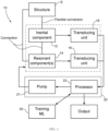
- a micro-electro-mechanical system (MEMS) device is generally illustrated at 10.
- the MEMS device 10 may be referred to as a neuromorphic MEMS device 10.
- the MEMS device 10 is of the type used with a structure S that is exposed to external stimuli.
- structure is used as the structure S supports the MEMS device 10.
- the structure S may be movable or may have movable components, or may be deformable or may have deformable components, though the structure S may be fixed as well. Embodiments described below give examples of such structure S.
- the MEMS device 10 may be an integral and/or native part of the structure S, or may be added on or retrofitted to the structure S.
- the MEMS device 10 has an inertial component 12, and one or more resonant components 14.
- the inertial component 12 is connected to the structure S by a flexible connection. Therefore, because of the flexible connection, the inertial component 12 may deform and/or move relative to the structure S in response to an external stimulus applied to the structure S.
- the resonant component(s) 14 may be connected to the structure S and/or the inertial component 12.
- the resonant component(s) 14 has one or more resonant modes, that will be driven during the use of the MEMS device 10.
- the resonant component(s) 14 defines the physical node(s) of a reservoir computer, with the resonant component(s) 14 being exposed to the external physical stimuli (e.g., acceleration, pressure) through the structure S and/or inertial component 12.
- the resonant component(s) 14 is selected to have a relatively high resonant frequency (>10 5 Hz) in order for the reservoir computer to have adequate performance.
- the resonant component(s) 14 may consequently be of relatively high stiffness and/or be of relatively low mass (e.g., ⁇ 10 -10 g) and area (e.g., ⁇ 10 -9 m 2 ), which makes them relatively insensitive to external stimuli such as acceleration or pressure.
- the resonant component(s) 14 may be interfaced to the structure S and/or inertial component 14, which are more sensitive to external stimuli.
- the displacements of these relatively larger structures is coupled to the displacement of the small resonant components 14 through an electrostatic force between them, the electrostatic force being dependent on the distance separating them.
- the resonant component(s) may be between 10 000 to 100 000 times less sensitive than the larger inertial components (i.e., the inertial component 14 and/or the structure S) to external stimuli (e.g., acceleration, sound pressure).
- the expressions "inertial” and "resonant” are used to illustrate the contrast between the components 12 and 14.
- One or more transduction unit 16 may be provided to measure the oscillatory motion of the resonant component(s) 14 relative to the structure S.
- the transduction unit 16 may take various forms as exemplified below (e.g., piezo-resistive, capacitive, optical).
- one or more transduction unit 18 may be provided to measure the movement or deformation of the inertial component 12, for example relative to the structure S.
- the transduction unit 18 may take various forms as exemplified below, and may be optional in a neuromorphic mode of the MEMS device 10.
- the position of the inertial component 12 relative to the structure S may be obtained by measuring the capacitance of an interdigitated comb structure, with one half mounted on the inertial component 12, and one half fixed to the structure S.
- the resulting measurement signal could be similar to the signal produced by a conventional MEMS accelerometer, i.e., an accelerometer that does not have neuromorphic computing capabilities.
- the position of the inertial component 12 relative to the structure S may be obtained by measuring the capacitance between the inertial component 12 and the structure S.
- the resulting measurement signal could be similar to the signal produced by a conventional MEMS microphone, i.e., a microphone that does not have neuromorphic computing capabilities.
- the mechanical components of the MEMS device 10 may be coupled to an electronic control unit (ECU) 20 to drive the resonant component(s) 14, measure the oscillatory motion and characterize it as a function of the external stimulus.
- the ECU 20 may have a pump voltage signal that creates a pump 21, the pump signal being wired to physical components of the MEMS device 10, i.e., the inertial component 12 and/or the resonant component(s) 14, and optionally to the structure S.
- the pump 21 applies an electrostatic force on the MEMS device 10, to induce an oscillatory motion of the resonant component(s) 14 in a predetermined resonant mode thereof, the oscillatory motion being a non-linear function of a strength of the electrostatic force.
- the resonant component(s) 14 is mechanically coupled to the inertial component 12 and/or the structure S such that a deformation and/or motion of the inertial component 12 and/or of the structure S in response to an external stimulus changes the strength of the pump 21.
- the electrostatic force acting on the inertial component 12 and/or on the structure S is selected to have a magnitude having negligible effect on them (e.g., causing virtually no displacement), as it is at a relatively high frequency (>10 5 Hz to match the natural frequency of the resonant component(s) 14), while the inertial component 12 and/or the structure S are only sensitive at much lower frequencies ( ⁇ 10 4 Hz).
- the ECU 21 generates the pump by applying an alternating voltage difference between the resonant component(s) 14, and the inertial component 12 and/or the structure S.
- the oscillatory motion is induced in the resonant component(s) 14 through electrostatic forces resulting from this electrostatic coupling.
- the amplitude of this oscillatory motion is governed by the amplitude of the pump and by the gap between the inertial component 12 and/or structure S and the resonant component 14.
- the gap between the resonant component(s) 14 and the inertial component 12 and/or structure S is modified.
- a strength of the electrostatic pump is modulated, and the magnitude of the strength may be used in neuromorphic mode of the MEMS device 10.
- the ECU 20 may include a processor 22 for producing measured characteristics of the oscillatory motion as measured by the transduction unit(s) 16, the processor 22 producing an output signal being a mathematical function of said measured characteristics.
- the processor 22 may operate in conjunction with non-transitory computer-readable memory of the ECU 20, the computer-readable memory communicatively coupled to the processor 22 and comprising computer-readable program instructions executable by the processor 20.
- the processor 22 is an integrated circuit component that may produce the output signal for use by another computer system, or for communication to a user.
- the processor 22 is an electrical circuit producing the pump 21 in the form of an AC voltage difference between the resonant component 14 and the inertial component 12, and a position-dependent voltage from the transduction unit(s) 16.
- the computing by the processor 22 includes measuring a plurality of characteristics of the oscillatory motion as a function of time to construct an output signal.
- the amplitude of the output signal is a mathematical function of the measured characteristics. This mathematical function may be computed so as to minimize the mean error between the output signals and target signals during a training phase, where a plurality of external stimuli are applied sequentially, each stimulus corresponding to a target signal.
- the measured characteristics of the oscillatory motion may include the deflection of the resonant component(s) 14 measured at N equally-spaced instants in time, using the transducer unit(s) 16.
- the measured characteristics may be the position of the resonant component(s) at instants of time.
- the measured characteristics may be the voltage drop across a piezoresistive strain gauge configured to measure the displacement of the resonant component(s) 14.
- the mathematical function for creating the output signal is the linear combination of the measured characteristics, computed with a set of weights.
- y' is the target vector
- X are the measured characteristics in matrix form
- ⁇ is a small regularization parameter
- I is the identity matrix.
- the mechanical non-linearity of the MEMS device 10 may be used to implement a computing device that works in the mechanical domain, in a manner similar to neuro-computing.
- the output of the MEMS device 10 is produced by linearly combining the measured characteristics from the transduction unit(s) 16 of selected nodes in a network, which can be real or virtual.
- a network which can be real or virtual.
- a single MEMS device 10 is used and the network may be created by amplitude-modulating the pump signal with a binary mask.
- numerous MEMS device 10 may be used and the resonant components could, for example, be micro beams of silicon connected via small flexure springs so the beams can each oscillate and exchange energy via the flexure springs.
- the amplitude of the pump 21 may be modulated by a binary mask.
- the binary mask may have a certain duration, and may change value at fixed times.
- the values of the mask may be chosen between two levels, such that at every time step, the pump 21 may have an amplitude which is given by one of the two levels.
- the ECU 20 may store in its memory values of the measured characteristics that are sampled at every time period r.
- the ECU 20 may store up to N consecutive values in a vector x, discarding values that were stored a time larger than N r in the past.
- the ECU 20 may store the values y consecutively in memory.
- the ECU 20 may then set the amplitude of the pump voltage to be the product of the binary mask at the current time, and of the value of the linear combination y that was stored M time steps in the past.
- the values M and N may be equal.
- the ECU 20 may be used in conjunction with a machine-learning (ML) module 30 or like training system, for the output signal to be in a desired form.
- the ML module 30 may be part of the ECU 20 as well.
- the ML module 30 may obtain feedback of the user as to a nature or form of the desired output, which feedback is an integral part of the training.
- the ML module 30 may include at least 100 captures of measured characteristics that are synchronized with the application of external stimuli.
- the learning module 30 may produce and output an optimal set of weights to from a linear combination of the measured characteristics.
- the ML algorithm may be selected from different supervised or unsupervised machine learning algorithms.
- the ML algorithm may help train the ECU 20 such that the mathematical function may have its parameters calculated by minimizing a mean error between output signals and target signals during a training phase, where a plurality of external stimuli are applied sequentially, each stimulus corresponding to a target signal.
- the mathematical function may be the linear combination of the characteristics of the measured oscillatory motion, computed with a set of weights.
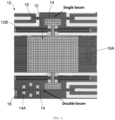
- FIG. 2 an embodiment of the MEMS device 10 is shown in greater detail. Like reference numerals in Figs. 1 and 2 will refer to corresponding elements.
- the MEMS device 10 of Fig. 2 has its resonant component 14 electrostatically coupled to the inertial component 12.
- the MEMS device 10 has, as resonant component 14, a silicon beam, although other materials may be used.
- the resonant component 14 is supported by a substrate that is the structure S supporting the MEMS device 10.
- anchors 14A support the resonant component 14.
- the resonant component 14 is also suspended over the substrate S by the anchors 14A.
- the anchors 14A are designed to allow vibrations of the resonant component 14, for instance by clamping the beam at or near its opposite ends.
- the resonant component 14 may consist of a single beam.
- the resonant components 14 may also include multiple beams, such as beams attached to one another in order to define a mechanical network.
- the transduction units 16 or like sensors may be in the form of gauges used to measure oscillations of the resonant component 14.
- the gauges may be piezo-resistive gauges transversally attached to the beam.
- Other types of sensors may also be used to measure the oscillations of the resonant component 14.
- the MEMS device 10 also has the inertial component 12 in the form of a mass 12A.
- the mass 12A is connected to the substrate S, by a flexible connection including one or more flexible members 12B, allowing the inertial component 12 to deform or move relative to the substrate S in response to an applied external stimulus.
- the mass 12A is an inertial proof mass
- the flexible member 12B may be compliant springs and/or flexure springs, among possibilities.
- the inertial proof mass 12A may be suspended over the substrate S by compliant springs 12B. As observed from Fig. 2 , a gap is present between the beam 14 and the inertial proof mass 12A. According to an embodiment, the compliant springs 12B constrain the inertial proof mass 12A to in-plane, uniaxial displacement in response to external stimuli, i.e., one translational degree of freedom, toward and away the beam 14. This motion of the proof mass 12A modulates the force acting on the resonant beam 14. This constitutes a coupling arrangement between the beam 14 and the proof mass 12A. Other embodiments are contemplated, with beams 14 along other sides, and bi-directional movement of the proof mass 12A, as another possibility. As another example, the inertial component 12 may be a single monolithic component including a cantilever beam supporting a mass portion about a frame.
- transduction unit(s) 18 may be used to measure the displacement of the inertial component 12.
- the displacement of the inertial component 12 may be assessed by measuring a change in capacitance between interdigitated electrodes 18A.
- the interdigitated electrodes 18A may include combs attached to the proof mass 12A so as to move concurrently with the proof mass 12A, while combs are connected to the substrate S, and thus remain fixed relative to the combs connected to the proof mass 12A.
- the transduction unit(s) 18 may be used to validate the measured characteristics of the oscillatory motion measured by the gauges 16, and may hence be optional.
- the resonant component(s) 14 of the MEMS device 10 is electrostatically driven at a frequency near its natural frequency, via pump 21 ( Fig. 1 ).
- the electrostatic drive may be achieved by applying a signal (e.g., alternating (AC) voltage) to the resonant component(s) 14.
- a signal e.g., AC voltage
- the compliant springs 12A constrain the inertial proof mass 12A to the in-plane, uniaxial movement as a response to and external stimulus, while the beam 14 is designed to move parallel to the plane of the substrate S.
- the movement of the proof mass 12A modulates the electrostatic force acting on the resonant beam 14, and thus modulates the strength of the pump 21.
- a virtual network is created by modulating the amplitude of the sinusoidal pump voltage signal from the pump 21 with a repetitive mask pattern.
- the strength of the pump 21 is also a mathematical function of the oscillation amplitude of the beam 14 from an instant in the past, i.e., delayed feedback.
- the measured characteristics of the oscillatory motion include the deflection of the beam 14 measured at N equally-spaced instants in time, using for example the gauges 16.
- the mathematical function described above may then be used by the ECU 20 to produce the output signal.
- the pump 21 is an alternating electric field between the resonant component 14 and the inertial component 12, the field being created by the processor 22 applying an AC voltage difference between the resonant component 14 and the inertial component 12.
- the pump 21 induces an oscillatory motion of the resonant component 14 in the resonant mode.
- the oscillatory motion induced by the ECU 20 is a non-linear function of the strength of the pump 21.
- the coupling arrangement between the resonant component 14 and the inertial component 12 causes a change in the strength of the pump 21 as a result of deformation and/or motion of the inertial component 12 in response to an external stimulus.
- the ECU 20 may hence calculate a plurality of measured characteristics of the oscillatory motion, and consequently produce an output signal, whose amplitude is a mathematical function of the measured characteristics of the oscillatory motion.
- the mathematical function is only a function of the oscillatory motion of the resonant component(s) 14.
- the oscillatory motion is a function of the pump 21, which itself is a function of the pump voltage and of the stimulus.
- the arrangement described above for Fig. 2 may be used as an electromechanical recurrent neural network (RNN) microfabricated (typically in silicon) using MEMS technology.
- the inertial component 12 acts as an intermediary to interface inertial forces with the resonant component 14, i.e., the MEMS RNN, implemented as a reservoir computer (RC).
- the inertial component 12 is placed in close proximity to the resonant component(s) 14 and is polarized with a sinusoidal pump voltage signal, such that an electrostatic force, the pump 21, drives the mechanical modes of the RC.
- the electrostatic driving force is modulated by varying the distance between the resonant component 14, acting as MEMS RC, and the inertial mass 12A.
- the resonant MEMS device 10 may be used as an artificial neuron exploited in the mechanical domain, in a manner similar to neuro-computing.
- the output of the RC is produced by linearly combining the piezo-resistive or capacitive displacement signals of selected nodes in the network, which can be real or virtual.
- the MEMS device 10 may be used with a substrate made of a silicon-on-insulator (SOI) wafer with a silicon layer of 50 um and an oxide layer of 4 um.
- the microfabrication process may include, as an example, 1) Photolithography of the Si layer: - Spin of AZ1512 photoresin, - Exposition, 60 mJ/cm 2 , - Development; 2) Advanced silicon etching; 3) Photolithography of the metal layer: - Spin of NR4 8000P, - Exposition, 500 mJ/cm 2 , - Development; 4) Metallization; 5) Lift-off; 6) HF vapor liberation.
- This is an exemplary fabrication method.
- the MEMS device 10 of Fig. 3 has two or more resonant components 14, in the form of two distinct beams.
- the use of multiple resonant components 14 in any of the embodiments described herein may assist in an accuracy of the neuromorphic computing of the MEMS device 10, by allowing a larger number of measured oscillatory characteristics and/or increasing the relevance of the measured oscillatory characteristics for neuromorphic computing due to the richer dynamics provided by multiple coupled resonant components 14.
- the use of the multiple resonant components 14 may allow the MEMS device 10 to operate under different resonant frequencies (e.g., one distinct resonant frequency per resonant component 14) and/or with different electrostatic coupling gaps, resulting in such scenarios in different mechanical responses from the multiple resonant components 14, each one of the multiple resonant components responding to a different amplitude variation of the pump 21.
- Each resonant component 14 may be coupled to its own processor 22 of a same ECU 20, or of different ECU 20.
- the different amplitude variations may lead to the processors 22 performing differently on different tasks. For example, with two components 14 and two processors 22, one may perform well on task A, and poorly on task B. The situation might be inverted for the other component 14, which may perform well on task B, and poorly on task A. Combining the output of both components 14 may lead to a system that performs well on task A and on task B.
- FIG. 4 and 5 another embodiment of the MEMS device 10 is shown, in which the resonant component(s) 14 is(are) electrostatically coupled to the structure S, as opposed to being electrostatically coupled to the inertial component 12.
- the MEMS device 10 of Figs. 4 and 5 may be used for example as a MEMS microphone, similar in its constitution and function to the neuromorphic MEMS inertial device 10.
- the MEMS device 10 of Figs. 4 and 5 comprises an electrically conductive structure S to which the inertial component 12 in the form of a membrane 12A, such as a regular polygonal plate, is connected through flexible members 12B arranged periodically around the plate 12A and anchored at one end.
- This configuration allows the plate 12A to move or deform in a direction normal to its plane in response to sound pressure exerting a force on the plate 12A.
- the flexible members 12B may be suspension units composed of folded compliant silicon beams.
- the plate 12A deforms and its flexible connection is through its elastic deformation relative to the structure S.
- a cylindrical hole S1 is defined in the structure S (e.g., etched) in order to relieve back pressure upon displacement of the plate 12A and to prevent the electrostatic pull-in (collapse) of the plate 12A onto the structure S.
- the resonant components 14 are embedded in the plate 12A.
- the resonant components 14 in Figs. 4 and 5 may for example be one or more silicon beams patterned in the suspended plate 12 and anchored to this plate at both ends.
- a piezoresistor may be patterned over the resonant component(s) 14, to measure its oscillations.
- the piezoresistor may be a small area of p-type silicon embedded in a larger intrinsic or n-type region.
- the flexible connection of the sensing plate 12A constraint same to an out-of-plane, uniaxial movement as a response to the external sound pressure stimulus.
- the beam(s) 14 is(are) also designed to move in a direction normal to the plane of the sensing plate 12A.
- the movement of the sensing plate 12A modulates the strength of the electrostatic force acting on the resonant beam(s) 14 by varying the gap between the resonant beam(s) 14 and the drive electrode S2.
- the high frequency oscillatory motion of the resonant component(s) 14 is driven by an electrostatic pump 21 ( Fig. 1 ), wherein polarizing the structure with respect to the resonant components 14 via a sinusoidal electrical signal of the pump 21 generates an attractive force between a fixed driving electrode S2 of the structure S and the individual resonant components 14.
- the strength of the pump 21 is coupled to the external sound pressure stimuli through the induced displacement of the plate 12A. This results in a variation in the gap between the resonant components 14 and the driving electrode S2 of the structure S.
- the resonant component(s) 14 is(are) electrostatically driven at a frequency near its(their) natural frequency.
- the processor 22 (e.g., a microcontroller) measures a plurality of characteristics of the oscillatory motion of the resonant components 14, the processor 22 producing an output signal, wherein the amplitude of the output signal is a mathematical function of the measured characteristics, such as a linear combination using weights computed to achieve a specific task.
- the task is to produce an output signal that varies in voltage between distinct levels (e.g., 10 levels), each level corresponding to a particular word spoken by a person, with the sound pressure being detected by the microphone MEMS device 10. This is an example among others.
- the MEMS device 10 of Figs. 4 and 5 may include a structure S made of a silicon-on-insulator (SOI) wafer with a silicon device layer of 10 um (in which the moving parts are defined) and an oxide layer of 5 um (defining the gap distance).
- the microfabrication process may include: 1) Photolithography and advanced silicon etching of the substrate; 2) Photolithography of the Si device layer: - Piezoresistor patterning and ion implantation, - Mechanical structures definition and subsequent advanced silicon etching (ASE); 3) Photolithography of the metal layer: - Patterning of the electrical traces and wirebonding pads: - Metal evaporation and lift-off; and 4) HF vapour release of suspended mechanical structures.
- the electronic control unit 20 may be a system that performs given tasks with the external stimulus on the mechanical components of the MEMS device 10.
Landscapes
- Engineering & Computer Science (AREA)
- Physics & Mathematics (AREA)
- Theoretical Computer Science (AREA)
- General Physics & Mathematics (AREA)
- Health & Medical Sciences (AREA)
- Life Sciences & Earth Sciences (AREA)
- Biomedical Technology (AREA)
- Biophysics (AREA)
- Molecular Biology (AREA)
- Software Systems (AREA)
- Evolutionary Computation (AREA)
- General Health & Medical Sciences (AREA)
- Computational Linguistics (AREA)
- Computing Systems (AREA)
- General Engineering & Computer Science (AREA)
- Artificial Intelligence (AREA)
- Mathematical Physics (AREA)
- Data Mining & Analysis (AREA)
- Acoustics & Sound (AREA)
- Computer Hardware Design (AREA)
- Microelectronics & Electronic Packaging (AREA)
- Automation & Control Theory (AREA)
- Neurology (AREA)
- Signal Processing (AREA)
- Micromachines (AREA)
Claims (15)
- Dispositif de type microsystème électromécanique, MEMS, (10) comprenant :un composant inertiel (12, 12A) configuré pour être relié à une structure (S) par une liaison flexible (12B) permettant au composant inertiel (12, 12A) de se déformer dans une déformation ou de se déplacer dans un mouvement par rapport à la structure (S) en réponse à un stimulus externe appliqué à la structure (S) ;au moins un composant résonnant (14) adapté pour être relié à l'un de ladite structure et dudit composant inertiel (12, 12A), le composant résonnant (14) étant couplé par l'intermédiaire d'un couplage à l'autre de ladite structure (S) et dudit composant inertiel (12, 12A), le composant résonnant ayant au moins un mode résonnant ;au moins une unité de transduction (16) pour mesurer un mouvement oscillatoire de l'au moins un composant résonnant (14) par rapport au composant inertiel (12, 12A) et/ou à la structure (S) ; etune unité de commande électronique (20) configurée pour appliquer une pompe (21) de force électrostatique pour induire un mouvement oscillatoire de l'au moins un composant résonnant (14) dans ledit mode résonnant, le mouvement oscillatoire étant une fonction non linéaire d'une résistance de la force électrostatique, dans lequel ledit couplage de l'au moins un composant résonnant (14) est tel que ladite déformation ou ledit mouvement du composant inertiel (12, 12A) en réponse à un stimulus externe change la résistance de la pompe (21), l'unité de commande électronique (20) étant configuré pour produire et délivrer un signal de sortie qui est une fonction mathématique du mouvement oscillatoire mesuré.
- Dispositif MEMS (10) selon la revendication 1, dans lequel l'au moins un composant résonnant (14) est une poutre fixée au niveau ou à proximité d'extrémités opposées de celui-ci.
- Dispositif MEMS (10) selon la revendication 2, dans lequel le composant inertiel (12, 12A) est une masse d'épreuve inertielle (12A) supportée par des ressorts, et séparée de la poutre (14) par un espacement.
- Dispositif MEMS (10) selon la revendication 3, dans lequel la masse d'épreuve inertielle (12A) se déplace dans un degré de liberté de translation unique vers la poutre (14) et à l'écart de celle-ci.
- Dispositif MEMS (10) selon l'une quelconque des revendications 2 à 4, dans lequel la pompe (21) est un champ électrique alternatif entre l'au moins un composant résonnant (14) et le composant inertiel (12, 12A), le champ étant créé par l'application d'une différence de tension CA entre l'au moins un composant résonnant (14) et le composant inertiel (12, 12A).
- Dispositif MEMS (10) selon l'une quelconque des revendications 2 à 5, dans lequel le mouvement oscillatoire mesuré inclut une amplitude d'oscillation de la poutre mesurée à N instants temporels équidistants.
- Dispositif MEMS (10) selon la revendication 1, dans lequel l'au moins un composant résonnant (14) est une poutre reliée, au niveau de ses extrémités opposées, au composant inertiel (12, 12A) et dans lequel, facultativement, le composant inertiel (12, 12A) est une plaque (12A) dont la périphérie est en liaison flexible avec la structure (S) et dans lequel, facultativement, la structure (S) comporte une électrode séparée de l'au moins un composant résonnant par un espacement et couplée à l'au moins un composant résonnant.
- Dispositif MEMS (10) selon la revendication 7, dans lequel la pompe (21) est un champ électrique alternatif entre l'au moins un composant résonnant (14) et l'électrode, le champ étant créé par l'application d'une différence de tension CA entre l'au moins un composant résonnant (14) et le composant inertiel (12, 12A).
- Dispositif MEMS (10) selon l'une quelconque des revendications 1 à 8, dans lequel ladite fonction mathématique comporte des paramètres, et lesdits paramètres sont calculés par la minimisation d'une erreur moyenne entre des signaux de sortie et des signaux cibles au cours d'une phase d'entraînement, où une pluralité de stimuli externes sont appliqués séquentiellement, chaque stimulus correspondant à un signal cible.
- Dispositif MEMS (10) selon l'une quelconque des revendications 1 à 9, dans lequel ladite fonction mathématique est la combinaison linéaire de N caractéristiques mesurées dudit mouvement oscillatoire, calculée avec un ensemble de poids.
- Dispositif MEMS (10) selon l'une quelconque des revendications 1 à 10, dans lequel ladite résistance de la pompe (21) est une fonction mathématique dudit signal de sortie, au temps courant ou à partir d'un instant passé.
- Dispositif MEMS (10) selon l'une quelconque des revendications 1 à 11, dans lequel l'unité de transduction inclut des extensomètres piezorésistifs reliés à moins un composant résonnant (14).
- Dispositif MEMS (10) selon l'une quelconque des revendications 1 à 12, dans lequel la pompe (21) est une force entre l'au moins un composant résonnant (14) et le composant inertiel (12), dans lequel ladite force varie de manière sinusoïdale dans le temps avec une amplitude et une fréquence et dans lequel, facultativement, ladite amplitude de la force sinusoïdale varie dans le temps en fonction d'un motif de masque répétitif.
- Dispositif MEMS (10) selon la revendication 13, dans lequel ladite fréquence est proche d'une fréquence naturelle du mode résonnant de l'au moins un composant résonnant.
- Système de production d'une sortie neuromorphique pour un dispositif MEMS (10) selon la revendication 1, exposé à des stimuli externes, le système comprenant :une unité de traitement (22) ; etune mémoire non transitoire lisible par ordinateur couplée en communication à l'unité de traitement et comprenant des instructions de programme lisibles par ordinateur exécutables par l'unité de traitement (22) pour amener le dispositif MEMS selon la revendication 1 à exécuter les étapes suivantes :l'application d'une pompe (21) de force électrostatique pour induire un mouvement oscillatoire d'au moins un composant résonnant (14) du dispositif MEMS (10) dans un mode résonnant de l'au moins un composant résonnant (14), le mouvement oscillatoire étant une fonction non linéaire d'une résistance de la pompe (21) de force électrostatique,le couplage de l'au moins un composant résonnant (14) à un composant inertiel (12, 12A) ou à une structure (S) dans le dispositif MEMS (10) de sorte qu'une déformation ou un mouvement du composant inertiel (12, 12A) en réponse à un stimulus externe change la résistance de la pompe (21),la mesure du mouvement oscillatoire de l'au moins composant résonnant (14),la production et la délivrance d'un signal de sortie qui est une fonction mathématique du mouvement oscillatoire mesuré.
Applications Claiming Priority (2)
| Application Number | Priority Date | Filing Date | Title |
|---|---|---|---|
| US201862780589P | 2018-12-17 | 2018-12-17 | |
| PCT/CA2019/051832 WO2020124219A1 (fr) | 2018-12-17 | 2019-12-17 | Dispositif de type microsystème électromécanique neuromorphique |
Publications (4)
| Publication Number | Publication Date |
|---|---|
| EP3898502A1 EP3898502A1 (fr) | 2021-10-27 |
| EP3898502A4 EP3898502A4 (fr) | 2022-09-14 |
| EP3898502C0 EP3898502C0 (fr) | 2024-07-31 |
| EP3898502B1 true EP3898502B1 (fr) | 2024-07-31 |
Family
ID=71100126
Family Applications (1)
| Application Number | Title | Priority Date | Filing Date |
|---|---|---|---|
| EP19900848.3A Active EP3898502B1 (fr) | 2018-12-17 | 2019-12-17 | Dispositif de type microsystème électromécanique neuromorphique |
Country Status (6)
| Country | Link |
|---|---|
| US (1) | US12344523B2 (fr) |
| EP (1) | EP3898502B1 (fr) |
| JP (1) | JP7422770B2 (fr) |
| CN (1) | CN113226975B (fr) |
| CA (1) | CA3123944A1 (fr) |
| WO (1) | WO2020124219A1 (fr) |
Families Citing this family (4)
| Publication number | Priority date | Publication date | Assignee | Title |
|---|---|---|---|---|
| WO2022024308A1 (fr) * | 2020-07-30 | 2022-02-03 | Tdk株式会社 | Dispositif de traitement d'informations et dispositif de détection de mouvement |
| US11965907B2 (en) | 2022-04-02 | 2024-04-23 | Emcore Corporation | Resonantly vibrating accelerometer driven in multiple vibrational modes |
| US11959935B2 (en) | 2022-04-02 | 2024-04-16 | Emcore Corporation | Resonantly vibrating accelerometer with cross-coupling signal suppression |
| US11953514B2 (en) * | 2022-04-02 | 2024-04-09 | Emcore Corporation | Self-compensating resonantly vibrating accelerometer driven in multiple vibrational modes |
Family Cites Families (59)
| Publication number | Priority date | Publication date | Assignee | Title |
|---|---|---|---|---|
| JP2728807B2 (ja) | 1991-07-24 | 1998-03-18 | 株式会社日立製作所 | 静電容量式加速度センサ |
| AU3623500A (en) | 1999-03-12 | 2000-09-28 | Graviton, Inc. | Systems and methods for network based sensing and distributed sensor, data and memory management |
| US6763340B1 (en) | 2000-09-22 | 2004-07-13 | The United States Of America As Represented By The Secretary Of The Air Force | Microelectromechanical system artificial neural network device |
| FI111457B (fi) | 2000-10-02 | 2003-07-31 | Nokia Corp | Mikromekaaninen rakenne |
| US7392230B2 (en) | 2002-03-12 | 2008-06-24 | Knowmtech, Llc | Physical neural network liquid state machine utilizing nanotechnology |
| WO2004065968A1 (fr) * | 2003-01-16 | 2004-08-05 | The Regents Of The University Of Michigan | Dispositif accelerometrique transversal capacitif micro-usine et accelerometre tri-axial monolithique comprenant un tel dispositif |
| US7418876B2 (en) * | 2003-05-21 | 2008-09-02 | Armstrong William D | Oscillatory motion based measurement method and sensor for measuring wall shear stress due to fluid flow |
| US9907473B2 (en) | 2015-04-03 | 2018-03-06 | Koninklijke Philips N.V. | Personal monitoring system |
| US7581324B1 (en) | 2007-01-12 | 2009-09-01 | Snap-On Incorporated | Wheel alignment system using smart MEMS |
| US8898036B2 (en) | 2007-08-06 | 2014-11-25 | Rosemount Inc. | Process variable transmitter with acceleration sensor |
| US8315793B2 (en) * | 2009-06-03 | 2012-11-20 | Honeywell International Inc. | Integrated micro-electro-mechanical systems (MEMS) sensor device |
| US8818923B1 (en) | 2011-06-27 | 2014-08-26 | Hrl Laboratories, Llc | Neural network device with engineered delays for pattern storage and matching |
| WO2012047356A2 (fr) | 2010-07-26 | 2012-04-12 | The University Of Vermont | Utilisations de systèmes de degrés de liberté équilibrés entre des états entièrement quantiques et entièrement classiques |
| FR2964651B1 (fr) | 2010-09-13 | 2015-05-15 | Commissariat Energie Atomique | Dispositif a poutre suspendue et moyens de detection piezoresistive du deplacement de celle-ci, et procede de fabrication du dispositif |
| US9705450B2 (en) | 2011-06-24 | 2017-07-11 | The United States Of America As Represented By The Secretary Of The Navy | Apparatus and methods for time domain measurement of oscillation perturbations |
| US9092729B2 (en) | 2011-08-11 | 2015-07-28 | Greenray Industries, Inc. | Trim effect compensation using an artificial neural network |
| WO2013188131A1 (fr) | 2012-06-13 | 2013-12-19 | Purdue Research Foundation | Système microélectromécanique (mems) et procédés d'utilisation |
| ITTO20120542A1 (it) * | 2012-06-20 | 2013-12-21 | St Microelectronics Srl | Dispositivo microelettromeccanico con instradamento dei segnali attraverso un cappuccio protettivo e metodo per controllare un dispositivo microelettromeccanico |
| US9541982B2 (en) | 2013-01-25 | 2017-01-10 | Wisconsin Alumni Research Foundation | Reconfigurable event driven hardware using reservoir computing for monitoring an electronic sensor and waking a processor |
| US9165246B2 (en) | 2013-01-29 | 2015-10-20 | Hewlett-Packard Development Company, L.P. | Neuristor-based reservoir computing devices |
| US20140260618A1 (en) | 2013-03-14 | 2014-09-18 | Agency For Science Technology And Research (A*Star) | Force feedback electrodes in mems accelerometer |
| US9300227B2 (en) | 2013-06-05 | 2016-03-29 | Silicon Laboratories Inc. | Monolithic body MEMS devices |
| WO2014203038A1 (fr) | 2013-06-19 | 2014-12-24 | Aselsan Elektronik Sanayi Ve Ticaret Anonim Sirketi | Système et procédé pour mettre en œuvre un calcul de réservoir dans un dispositif d'imagerie par résonance magnétique à l'aide de techniques d'élastographie |
| WO2014203039A1 (fr) | 2013-06-19 | 2014-12-24 | Aselsan Elektronik Sanayi Ve Ticaret Anonim Sirketi | Système et procédé de mise en œuvre d'un calcul de réservoir à l'aide d'automates cellulaires |
| US9940574B1 (en) * | 2013-06-26 | 2018-04-10 | Hrl Laboratories, Llc | System and method to control a model state of a neuromorphic model of a brain |
| EP2821942B1 (fr) | 2013-07-05 | 2020-11-04 | Universiteit Gent | Calcul de réservoir à l'aide de systèmes optiques passifs |
| CN103581080B (zh) | 2013-10-28 | 2017-01-25 | 温州大学 | 基于储备池计算的复数域多值通信信号盲检测方法 |
| US9987743B2 (en) | 2014-03-13 | 2018-06-05 | Brain Corporation | Trainable modular robotic apparatus and methods |
| US9346167B2 (en) | 2014-04-29 | 2016-05-24 | Brain Corporation | Trainable convolutional network apparatus and methods for operating a robotic vehicle |
| US9630318B2 (en) | 2014-10-02 | 2017-04-25 | Brain Corporation | Feature detection apparatus and methods for training of robotic navigation |
| WO2016054340A1 (fr) | 2014-10-02 | 2016-04-07 | Board Of Regents, The University Of Texas System | Dispositifs memristors couplés permettant une commande retour et la détection d'un actionneur micro/nano-électromécanique et de capteurs |
| US9717387B1 (en) | 2015-02-26 | 2017-08-01 | Brain Corporation | Apparatus and methods for programming and training of robotic household appliances |
| US9990580B2 (en) * | 2015-03-13 | 2018-06-05 | International Business Machines Corporation | Neuromorphic synapses |
| US9749007B1 (en) | 2015-03-19 | 2017-08-29 | Hrl Laboratories, Llc | Cognitive blind source separator |
| US9672821B2 (en) | 2015-06-05 | 2017-06-06 | Apple Inc. | Robust speech recognition in the presence of echo and noise using multiple signals for discrimination |
| US9995647B2 (en) | 2015-09-30 | 2018-06-12 | General Monitors, Inc. | Ultrasonic gas leak location system and method |
| US10395168B2 (en) | 2015-10-26 | 2019-08-27 | International Business Machines Corporation | Tunable optical neuromorphic network |
| US10902115B2 (en) * | 2015-10-28 | 2021-01-26 | Hrl Laboratories, Llc | Neuromorphic system for authorized user detection |
| US10012616B2 (en) | 2015-11-06 | 2018-07-03 | Andritz Inc. | Acoustic emission system and method for predicting explosions in dissolving tank |
| US10636057B2 (en) | 2015-11-13 | 2020-04-28 | [24]7.ai, Inc. | Method and apparatus for dynamically selecting content for online visitors |
| US9655547B1 (en) | 2015-12-16 | 2017-05-23 | Hartford Fire Insurance Company | Microelectromechanical accelerometer based sensor system |
| EP3182339A1 (fr) | 2015-12-17 | 2017-06-21 | Vrije Universiteit Brussel | Dispositif de calcul de réservoir |
| US9610476B1 (en) | 2016-05-02 | 2017-04-04 | Bao Tran | Smart sport device |
| US9852372B1 (en) | 2016-06-03 | 2017-12-26 | International Business Machines Corporation | Reservoir computing device using external-feedback laser system |
| US10176425B2 (en) * | 2016-07-14 | 2019-01-08 | University Of Dayton | Analog neuromorphic circuits for dot-product operation implementing resistive memories |
| US10234477B2 (en) | 2016-07-27 | 2019-03-19 | Google Llc | Composite vibratory in-plane accelerometer |
| US10229341B2 (en) * | 2016-12-21 | 2019-03-12 | Volkswagen Ag | Vector engine and methodologies using digital neuromorphic (NM) data |
| US10031287B1 (en) | 2017-02-02 | 2018-07-24 | International Business Machines Corporation | Waveguide architecture for photonic neural component with multiplexed optical signals on inter-node waveguides |
| US10107959B2 (en) | 2017-02-02 | 2018-10-23 | International Business Machines Corporation | Waveguide architecture for photonic neural component |
| US10052026B1 (en) | 2017-03-06 | 2018-08-21 | Bao Tran | Smart mirror |
| US11188818B2 (en) | 2017-04-03 | 2021-11-30 | International Business Machines Corporation | Reservoir computing system |
| US10622786B2 (en) | 2017-04-20 | 2020-04-14 | International Business Machines Corporation | Laser apparatus and reservoir computing system |
| EP3746879B1 (fr) * | 2018-01-29 | 2023-06-21 | Shi, Alexander | Circuit intégré sécurisé à chaîne de blocs |
| US11314210B2 (en) * | 2018-08-01 | 2022-04-26 | Nutech Ventures | Neuromorphic computing using electrostatic mems devices |
| EP3830820B1 (fr) * | 2018-08-01 | 2025-11-12 | Syntiant | Systèmes de traitement de capteur comprenant des modules de traitement neuromorphiques et procédés associés |
| DE102018219760A1 (de) | 2018-11-19 | 2020-05-20 | Zf Friedrichshafen Ag | Kollisionsprädiktionssystem |
| US11112246B2 (en) * | 2019-06-14 | 2021-09-07 | United States Government As Represented By The Secretary Of The Army | Torsional oscillator micro electro mechanical systems accelerometer |
| CN111348611B (zh) | 2020-03-10 | 2023-05-09 | 西南大学 | 一种基于硅基微腔的类神经元光脉冲输出系统 |
| CN120092316A (zh) * | 2022-06-28 | 2025-06-03 | 英奇工厂股份有限公司 | 集成台式半导体工艺单元和由此类单元所形成的半导体制造生产线以及半导体工具库 |
-
2019
- 2019-12-17 CA CA3123944A patent/CA3123944A1/fr active Pending
- 2019-12-17 JP JP2021534342A patent/JP7422770B2/ja active Active
- 2019-12-17 CN CN201980083480.3A patent/CN113226975B/zh active Active
- 2019-12-17 WO PCT/CA2019/051832 patent/WO2020124219A1/fr not_active Ceased
- 2019-12-17 US US17/414,981 patent/US12344523B2/en active Active
- 2019-12-17 EP EP19900848.3A patent/EP3898502B1/fr active Active
Also Published As
| Publication number | Publication date |
|---|---|
| JP7422770B2 (ja) | 2024-01-26 |
| EP3898502A1 (fr) | 2021-10-27 |
| EP3898502C0 (fr) | 2024-07-31 |
| CN113226975B (zh) | 2024-04-12 |
| JP2022521566A (ja) | 2022-04-11 |
| WO2020124219A1 (fr) | 2020-06-25 |
| EP3898502A4 (fr) | 2022-09-14 |
| CA3123944A1 (fr) | 2020-06-25 |
| US12344523B2 (en) | 2025-07-01 |
| CN113226975A (zh) | 2021-08-06 |
| US20220063989A1 (en) | 2022-03-03 |
Similar Documents
| Publication | Publication Date | Title |
|---|---|---|
| EP3898502B1 (fr) | Dispositif de type microsystème électromécanique neuromorphique | |
| Barazani et al. | Microfabricated neuroaccelerometer: integrating sensing and reservoir computing in MEMS | |
| Hu et al. | Some design considerations on the electrostatically actuated microstructures | |
| EP3636588B1 (fr) | Ressorts à réglage de fréquence mems | |
| Leus et al. | On the dynamic response of electrostatic MEMS switches | |
| US20140074418A1 (en) | Method and system for calibrating an inertial sensor | |
| EP2867154B1 (fr) | Résonateur perfectionné | |
| Comi et al. | A resonant micro accelerometer based on electrostatic stiffness variation | |
| EP3234503B1 (fr) | Procédé de compensation de quadrature pour gyroscopes mems et un détecteur gyroscopique | |
| US20180209791A1 (en) | Motion measurement devices and methods for measuring motion | |
| CN215101976U (zh) | 微机电结构 | |
| EP2570770B1 (fr) | Technique d'oscillation couplée à trois masses pour gyroscopes micro-usinés mécaniquement robustes | |
| CN109239403B (zh) | 一种基于时间测量的单器件虚拟加速度计及其实现方法 | |
| Daruwalla et al. | A piezo-capacitive BAW accelerometer with extended dynamic range using a gap-changing moving electrode | |
| Alattar et al. | Exploiting nonlinearities of electrostatic MEMS resonators for tunable low pressure sensing | |
| US6012341A (en) | Force sensor having an adjustable distance between an operating point and a point of mechanical instability | |
| Cortés-Pérez et al. | Performance optimization and mechanical modeling of uniaxial piezoresistive microaccelerometers | |
| JP7563631B2 (ja) | アクチュエータユニット、触覚提示装置および筐体モジュール | |
| Pustan et al. | Dynamic behavior of smart microelectromechanical systems in industrial applications | |
| Basavanna et al. | Development of a Z-Axis out of plane MEMS accelerometer | |
| Ibrahim et al. | Enhancing the sensitivity of a resonant accelerometer | |
| Singha et al. | Analysis of a micromachined vibrating beam accelerometer for early earthquake warning system | |
| RU2657351C1 (ru) | Микроэлектромеханический первичный преобразователь ускорения | |
| Singha et al. | Parametric Studies of a Clamped-to-Clamped Resonant Beam Microelectromechanical System Based Acce, lerometer | |
| Shin | Advanced Frequency Output Resonant Mems Accelerometers |
Legal Events
| Date | Code | Title | Description |
|---|---|---|---|
| STAA | Information on the status of an ep patent application or granted ep patent |
Free format text: STATUS: THE INTERNATIONAL PUBLICATION HAS BEEN MADE |
|
| PUAI | Public reference made under article 153(3) epc to a published international application that has entered the european phase |
Free format text: ORIGINAL CODE: 0009012 |
|
| STAA | Information on the status of an ep patent application or granted ep patent |
Free format text: STATUS: REQUEST FOR EXAMINATION WAS MADE |
|
| 17P | Request for examination filed |
Effective date: 20210713 |
|
| AK | Designated contracting states |
Kind code of ref document: A1 Designated state(s): AL AT BE BG CH CY CZ DE DK EE ES FI FR GB GR HR HU IE IS IT LI LT LU LV MC MK MT NL NO PL PT RO RS SE SI SK SM TR |
|
| DAV | Request for validation of the european patent (deleted) | ||
| DAX | Request for extension of the european patent (deleted) | ||
| A4 | Supplementary search report drawn up and despatched |
Effective date: 20220817 |
|
| RIC1 | Information provided on ipc code assigned before grant |
Ipc: G06F 7/38 20060101ALI20220810BHEP Ipc: G01P 15/12 20060101ALI20220810BHEP Ipc: G01P 15/097 20060101ALI20220810BHEP Ipc: B81B 7/02 20060101ALI20220810BHEP Ipc: B81B 3/00 20060101AFI20220810BHEP |
|
| REG | Reference to a national code |
Ref country code: DE Ref legal event code: R079 Ipc: G01P0015097000 Ref country code: DE Ref legal event code: R079 Ref document number: 602019056358 Country of ref document: DE Free format text: PREVIOUS MAIN CLASS: B81B0003000000 Ipc: G01P0015097000 |
|
| GRAP | Despatch of communication of intention to grant a patent |
Free format text: ORIGINAL CODE: EPIDOSNIGR1 |
|
| STAA | Information on the status of an ep patent application or granted ep patent |
Free format text: STATUS: GRANT OF PATENT IS INTENDED |
|
| RIC1 | Information provided on ipc code assigned before grant |
Ipc: G06N 3/065 20230101ALI20240214BHEP Ipc: G06N 3/044 20230101ALI20240214BHEP Ipc: H04R 19/04 20060101ALI20240214BHEP Ipc: H04R 19/00 20060101ALI20240214BHEP Ipc: H04R 7/06 20060101ALI20240214BHEP Ipc: H03H 9/24 20060101ALI20240214BHEP Ipc: H03H 9/02 20060101ALI20240214BHEP Ipc: H03B 5/32 20060101ALI20240214BHEP Ipc: G06N 3/088 20230101ALI20240214BHEP Ipc: G01P 15/08 20060101ALI20240214BHEP Ipc: G01P 15/125 20060101ALI20240214BHEP Ipc: G01P 15/12 20060101ALI20240214BHEP Ipc: G01P 15/097 20060101AFI20240214BHEP |
|
| INTG | Intention to grant announced |
Effective date: 20240301 |
|
| GRAS | Grant fee paid |
Free format text: ORIGINAL CODE: EPIDOSNIGR3 |
|
| GRAA | (expected) grant |
Free format text: ORIGINAL CODE: 0009210 |
|
| STAA | Information on the status of an ep patent application or granted ep patent |
Free format text: STATUS: THE PATENT HAS BEEN GRANTED |
|
| AK | Designated contracting states |
Kind code of ref document: B1 Designated state(s): AL AT BE BG CH CY CZ DE DK EE ES FI FR GB GR HR HU IE IS IT LI LT LU LV MC MK MT NL NO PL PT RO RS SE SI SK SM TR |
|
| REG | Reference to a national code |
Ref country code: CH Ref legal event code: EP Ref country code: GB Ref legal event code: FG4D |
|
| REG | Reference to a national code |
Ref country code: DE Ref legal event code: R096 Ref document number: 602019056358 Country of ref document: DE |
|
| REG | Reference to a national code |
Ref country code: IE Ref legal event code: FG4D |
|
| U01 | Request for unitary effect filed |
Effective date: 20240731 |
|
| U07 | Unitary effect registered |
Designated state(s): AT BE BG DE DK EE FI FR IT LT LU LV MT NL PT RO SE SI Effective date: 20240902 |
|
| PG25 | Lapsed in a contracting state [announced via postgrant information from national office to epo] |
Ref country code: NO Free format text: LAPSE BECAUSE OF FAILURE TO SUBMIT A TRANSLATION OF THE DESCRIPTION OR TO PAY THE FEE WITHIN THE PRESCRIBED TIME-LIMIT Effective date: 20241031 |
|
| PG25 | Lapsed in a contracting state [announced via postgrant information from national office to epo] |
Ref country code: GR Free format text: LAPSE BECAUSE OF FAILURE TO SUBMIT A TRANSLATION OF THE DESCRIPTION OR TO PAY THE FEE WITHIN THE PRESCRIBED TIME-LIMIT Effective date: 20241101 Ref country code: PL Free format text: LAPSE BECAUSE OF FAILURE TO SUBMIT A TRANSLATION OF THE DESCRIPTION OR TO PAY THE FEE WITHIN THE PRESCRIBED TIME-LIMIT Effective date: 20240731 |
|
| PG25 | Lapsed in a contracting state [announced via postgrant information from national office to epo] |
Ref country code: IS Free format text: LAPSE BECAUSE OF FAILURE TO SUBMIT A TRANSLATION OF THE DESCRIPTION OR TO PAY THE FEE WITHIN THE PRESCRIBED TIME-LIMIT Effective date: 20241130 |
|
| PG25 | Lapsed in a contracting state [announced via postgrant information from national office to epo] |
Ref country code: HR Free format text: LAPSE BECAUSE OF FAILURE TO SUBMIT A TRANSLATION OF THE DESCRIPTION OR TO PAY THE FEE WITHIN THE PRESCRIBED TIME-LIMIT Effective date: 20240731 |
|
| PG25 | Lapsed in a contracting state [announced via postgrant information from national office to epo] |
Ref country code: RS Free format text: LAPSE BECAUSE OF FAILURE TO SUBMIT A TRANSLATION OF THE DESCRIPTION OR TO PAY THE FEE WITHIN THE PRESCRIBED TIME-LIMIT Effective date: 20241031 Ref country code: ES Free format text: LAPSE BECAUSE OF FAILURE TO SUBMIT A TRANSLATION OF THE DESCRIPTION OR TO PAY THE FEE WITHIN THE PRESCRIBED TIME-LIMIT Effective date: 20240731 |
|
| U20 | Renewal fee for the european patent with unitary effect paid |
Year of fee payment: 6 Effective date: 20241220 |
|
| PG25 | Lapsed in a contracting state [announced via postgrant information from national office to epo] |
Ref country code: RS Free format text: LAPSE BECAUSE OF FAILURE TO SUBMIT A TRANSLATION OF THE DESCRIPTION OR TO PAY THE FEE WITHIN THE PRESCRIBED TIME-LIMIT Effective date: 20241031 Ref country code: PL Free format text: LAPSE BECAUSE OF FAILURE TO SUBMIT A TRANSLATION OF THE DESCRIPTION OR TO PAY THE FEE WITHIN THE PRESCRIBED TIME-LIMIT Effective date: 20240731 Ref country code: NO Free format text: LAPSE BECAUSE OF FAILURE TO SUBMIT A TRANSLATION OF THE DESCRIPTION OR TO PAY THE FEE WITHIN THE PRESCRIBED TIME-LIMIT Effective date: 20241031 Ref country code: IS Free format text: LAPSE BECAUSE OF FAILURE TO SUBMIT A TRANSLATION OF THE DESCRIPTION OR TO PAY THE FEE WITHIN THE PRESCRIBED TIME-LIMIT Effective date: 20241130 Ref country code: HR Free format text: LAPSE BECAUSE OF FAILURE TO SUBMIT A TRANSLATION OF THE DESCRIPTION OR TO PAY THE FEE WITHIN THE PRESCRIBED TIME-LIMIT Effective date: 20240731 Ref country code: GR Free format text: LAPSE BECAUSE OF FAILURE TO SUBMIT A TRANSLATION OF THE DESCRIPTION OR TO PAY THE FEE WITHIN THE PRESCRIBED TIME-LIMIT Effective date: 20241101 Ref country code: ES Free format text: LAPSE BECAUSE OF FAILURE TO SUBMIT A TRANSLATION OF THE DESCRIPTION OR TO PAY THE FEE WITHIN THE PRESCRIBED TIME-LIMIT Effective date: 20240731 |
|
| PG25 | Lapsed in a contracting state [announced via postgrant information from national office to epo] |
Ref country code: SM Free format text: LAPSE BECAUSE OF FAILURE TO SUBMIT A TRANSLATION OF THE DESCRIPTION OR TO PAY THE FEE WITHIN THE PRESCRIBED TIME-LIMIT Effective date: 20240731 |
|
| PG25 | Lapsed in a contracting state [announced via postgrant information from national office to epo] |
Ref country code: CZ Free format text: LAPSE BECAUSE OF FAILURE TO SUBMIT A TRANSLATION OF THE DESCRIPTION OR TO PAY THE FEE WITHIN THE PRESCRIBED TIME-LIMIT Effective date: 20240731 |
|
| PG25 | Lapsed in a contracting state [announced via postgrant information from national office to epo] |
Ref country code: SK Free format text: LAPSE BECAUSE OF FAILURE TO SUBMIT A TRANSLATION OF THE DESCRIPTION OR TO PAY THE FEE WITHIN THE PRESCRIBED TIME-LIMIT Effective date: 20240731 |
|
| PLBE | No opposition filed within time limit |
Free format text: ORIGINAL CODE: 0009261 |
|
| STAA | Information on the status of an ep patent application or granted ep patent |
Free format text: STATUS: NO OPPOSITION FILED WITHIN TIME LIMIT |
|
| PG25 | Lapsed in a contracting state [announced via postgrant information from national office to epo] |
Ref country code: MC Free format text: LAPSE BECAUSE OF FAILURE TO SUBMIT A TRANSLATION OF THE DESCRIPTION OR TO PAY THE FEE WITHIN THE PRESCRIBED TIME-LIMIT Effective date: 20240731 |
|
| 26N | No opposition filed |
Effective date: 20250501 |
|
| REG | Reference to a national code |
Ref country code: CH Ref legal event code: PL |
|
| GBPC | Gb: european patent ceased through non-payment of renewal fee |
Effective date: 20241217 |
|
| PG25 | Lapsed in a contracting state [announced via postgrant information from national office to epo] |
Ref country code: GB Free format text: LAPSE BECAUSE OF NON-PAYMENT OF DUE FEES Effective date: 20241217 |
|
| PG25 | Lapsed in a contracting state [announced via postgrant information from national office to epo] |
Ref country code: CH Free format text: LAPSE BECAUSE OF NON-PAYMENT OF DUE FEES Effective date: 20241231 |
|
| PG25 | Lapsed in a contracting state [announced via postgrant information from national office to epo] |
Ref country code: IE Free format text: LAPSE BECAUSE OF NON-PAYMENT OF DUE FEES Effective date: 20241217 |
|
| U20 | Renewal fee for the european patent with unitary effect paid |
Year of fee payment: 7 Effective date: 20251205 |