EP3899057B1 - Procédé et dispositif de réduction directe à l'aide d'un gaz de réduction chauffé électriquement - Google Patents
Procédé et dispositif de réduction directe à l'aide d'un gaz de réduction chauffé électriquement Download PDFInfo
- Publication number
- EP3899057B1 EP3899057B1 EP19827679.2A EP19827679A EP3899057B1 EP 3899057 B1 EP3899057 B1 EP 3899057B1 EP 19827679 A EP19827679 A EP 19827679A EP 3899057 B1 EP3899057 B1 EP 3899057B1
- Authority
- EP
- European Patent Office
- Prior art keywords
- gas
- reformer
- reduction
- heating chamber
- heating
- Prior art date
- Legal status (The legal status is an assumption and is not a legal conclusion. Google has not performed a legal analysis and makes no representation as to the accuracy of the status listed.)
- Active
Links
Images




Classifications
-
- C—CHEMISTRY; METALLURGY
- C21—METALLURGY OF IRON
- C21B—MANUFACTURE OF IRON OR STEEL
- C21B13/00—Making spongy iron or liquid steel, by direct processes
- C21B13/0046—Making spongy iron or liquid steel, by direct processes making metallised agglomerates or iron oxide
-
- C—CHEMISTRY; METALLURGY
- C21—METALLURGY OF IRON
- C21B—MANUFACTURE OF IRON OR STEEL
- C21B13/00—Making spongy iron or liquid steel, by direct processes
- C21B13/004—Making spongy iron or liquid steel, by direct processes in a continuous way by reduction from ores
-
- C—CHEMISTRY; METALLURGY
- C21—METALLURGY OF IRON
- C21B—MANUFACTURE OF IRON OR STEEL
- C21B13/00—Making spongy iron or liquid steel, by direct processes
- C21B13/0073—Selection or treatment of the reducing gases
-
- C—CHEMISTRY; METALLURGY
- C21—METALLURGY OF IRON
- C21B—MANUFACTURE OF IRON OR STEEL
- C21B13/00—Making spongy iron or liquid steel, by direct processes
- C21B13/12—Making spongy iron or liquid steel, by direct processes in electric furnaces
-
- C—CHEMISTRY; METALLURGY
- C21—METALLURGY OF IRON
- C21B—MANUFACTURE OF IRON OR STEEL
- C21B2100/00—Handling of exhaust gases produced during the manufacture of iron or steel
- C21B2100/20—Increasing the gas reduction potential of recycled exhaust gases
- C21B2100/22—Increasing the gas reduction potential of recycled exhaust gases by reforming
-
- Y—GENERAL TAGGING OF NEW TECHNOLOGICAL DEVELOPMENTS; GENERAL TAGGING OF CROSS-SECTIONAL TECHNOLOGIES SPANNING OVER SEVERAL SECTIONS OF THE IPC; TECHNICAL SUBJECTS COVERED BY FORMER USPC CROSS-REFERENCE ART COLLECTIONS [XRACs] AND DIGESTS
- Y02—TECHNOLOGIES OR APPLICATIONS FOR MITIGATION OR ADAPTATION AGAINST CLIMATE CHANGE
- Y02P—CLIMATE CHANGE MITIGATION TECHNOLOGIES IN THE PRODUCTION OR PROCESSING OF GOODS
- Y02P10/00—Technologies related to metal processing
- Y02P10/10—Reduction of greenhouse gas [GHG] emissions
- Y02P10/134—Reduction of greenhouse gas [GHG] emissions by avoiding CO2, e.g. using hydrogen
-
- Y—GENERAL TAGGING OF NEW TECHNOLOGICAL DEVELOPMENTS; GENERAL TAGGING OF CROSS-SECTIONAL TECHNOLOGIES SPANNING OVER SEVERAL SECTIONS OF THE IPC; TECHNICAL SUBJECTS COVERED BY FORMER USPC CROSS-REFERENCE ART COLLECTIONS [XRACs] AND DIGESTS
- Y02—TECHNOLOGIES OR APPLICATIONS FOR MITIGATION OR ADAPTATION AGAINST CLIMATE CHANGE
- Y02P—CLIMATE CHANGE MITIGATION TECHNOLOGIES IN THE PRODUCTION OR PROCESSING OF GOODS
- Y02P10/00—Technologies related to metal processing
- Y02P10/10—Reduction of greenhouse gas [GHG] emissions
- Y02P10/143—Reduction of greenhouse gas [GHG] emissions of methane [CH4]
Definitions
- the invention relates to a method for the direct reduction of metal oxides using a reducing gas which is based on at least one precursor gas, at least one precursor gas being based on reformer gas obtained by catalytic reforming of hydrocarbon-containing gas in a reformer. It also relates to a device for the direct reduction of metal oxides by means of a reducing gas, comprising a catalytic reformer for producing a reformer gas, a reformer gas line for discharging reformer gas from the catalytic reformer, a reduction unit, and a reducing gas line for introducing reducing gas into the reduction unit.
- the production of metals by direct reduction of metal oxides by means of a reducing gas produced by reforming gases containing hydrocarbons is known - for example the MIDREX® process for the direct reduction of iron oxides is economically very important.
- the reducing gas is introduced into a reduction shaft filled with the metal oxide and reacts with the filling as it flows through.
- the reaction kinetics for the reduction are more favorable at a higher temperature of the reducing gas - in order to achieve a desired system output at a comparatively lower introduction temperature of the reducing gas, the specific
- the amount of reducing gas and possibly the system pressure must be increased, or raw materials that can be reduced more easily - for example pellets - would have to be used, which are associated with significantly higher costs.
- a method and a device are to be presented which allow the introduction temperature to be increased and the production output to be increased without the disadvantages of known methods.
- Reducing gas is a gas that is introduced into a reduction unit containing the metal oxides to be reduced—for example a reduction shaft or a fluidized bed unit—in order to at least partially reduce the metal oxides there.
- a reducing gas based on at least one precursor gas wherein at least one precursor gas is based on reformer gas obtained by catalytic reforming of hydrocarbon-containing gas in a reformer and is heated by means of electrical energy during the preparation of the reducing gas, is called reducing gas A, for example.
- reducing gas A can be used for direct reduction, or in addition to reducing gas A, another reducing gas or several further reducing gases - also called additional reducing gases - can be used - the conditions specified for reducing gas A do not have to apply to the further reducing gases.
- Catalytic reforming is the reaction of hydrocarbon-containing substances, in particular gases, with H 2 O and CO 2 in the presence of a catalyst in one catalytic reformer for the production of H 2 - and CO-containing gas, which is called reformer gas in this application.
- Reformer gas generally exits the reformer at an exit temperature in the range from 850°C to 970°C.
- the metal oxides preferably include iron oxides, more preferably they are iron oxides.
- Iron oxides are, for example, hematitic or magnetitic ores, or agglomerates such as iron ore pellets.
- At least one precursor gas is used in the preparation of the reducing gas.
- At least one precursor gas is based on the reformer gas; several precursor gases can also be based on the reformer gas.
- at least one precursor gas is heated using electrical energy.
- at least one precursor gas based on reformer gas is heated by means of electrical energy.
- Another precursor gas can, for example
- the reformer gas is the catalytic reforming of hydrocarbon-containing gas - such as natural gas, methane, liquefied natural gas LNG, liquefied petroleum gas LPG, coke oven gas COG, biogas; it can be a pure gas or a mixture of gases - product obtained in a reformer.
- Precursor gas based on the reformer gas can comprise at least a subset of the reformer gas, it can also comprise the entire reformer gas.
- Precursor gas based on the reformer gas can also consist of a subset of the reformer gas or the entire reformer gas.
- Precursor gas based on the reformer gas can also be produced by changing the reformer gas, for example by changing the pressure, temperature, composition.
- the composition can be changed, for example, by supplying other gases - such as natural gas - by separating gas components, by reactions in the reformer gas - such reactions can be caused, for example, by pressure or temperature changes or by supplying other gases.
- At least one precursor gas based on reformer gas is heated by means of electrical energy during the preparation of the reducing gas.
- a further precursor gas or several further precursor gases can also be heated by means of electrical energy.
- the precursor gas based on reformer gas is preferably heated by the electrical energy to a temperature which is to an extent of up to 200° C., preferably up to 100° C., particularly preferably up to 70° C., above that Outlet temperature from the reformer is.
- precursor gas based on reformer gas which exits the reformer at an exit temperature of 900°C, is heated to 970°C by the electrical energy.
- an upper limit of 200° C. preferably up to 100° C., particularly preferably up to 70° C., is provided for the temperature increase for the heating.
- the one further precursor gas or the several further precursor gases that are heated by electrical energy are preferably heated to a temperature which is up to 200° C. above the exit temperature of reformer gas from the reformer.
- the temperature must be increased by at least 10° C., particularly preferably at least 20° C., very particularly preferably at least 30° C., and extremely preferably at least 50° C. above the exit temperature preferred.
- the one further precursor gas or several further precursor gases that are heated by electrical energy are preferably heated to a temperature that is at least 10° C., particularly preferably at least 20° C., very particularly preferably at least 30° C. and most preferably at least 50°C above the outlet temperature.
- the reformer operation can be optimized without the associated lower temperature of the reformer gas having a negative effect on the productivity of the direct reduction.
- Changes in the temperature and also in the composition of the reducing gas favorable for improved productivity of the direct reduction can be carried out after the reforming.
- the reformer does not have to be operated beyond temperatures that are optimal for its function and favorable service life in order to ensure a desired reducing gas temperature or composition.
- the reformer can be operated carefully, which extends its service life, in particular the reformer tubes, due to less creeping in the longitudinal and diameter direction of the reformer tubes, or the service life of the catalyst in the reformer. This increases the efficiency of the direct reduction process.
- a reduced temperature level in the reformer also leads to a reduced temperature of the reformer exhaust gas and a reduced fuel requirement; the associated lower energy loss of the process increases the cost-effectiveness.
- aging-related degradation or deactivation of the catalyst in the reformer can be partially compensated for by the electrical heating, thereby delaying the need for complex and expensive replacement of the catalyst material.
- electrical heating can be used to heat up to temperatures that would not be achievable with heating in the reformer.
- the electrical heating according to the invention is advantageous especially when a direct reduction plant is put into operation for carrying out the method according to the invention. It opens up the possibility of in-situ reforming in a reducing gas that is based only or also on a reformer gas, in which only a few components are reformed - because the reformer is not yet fully operational when it is put into operation - by means of a quickly controllable temperature increase and/or after contact with the metal oxides.
- At least a portion of the electrical energy is introduced directly into the precursor gas to be heated by means of electrical energy, for example by means of resistance heating with a heating spiral, arc between electrodes.
- Direct introduction has the advantage that the efficiency is very high. This also has the advantage that nothing is added materially when the energy is introduced.
- the material composition of the reducing gas can be influenced because the energy input influences the kinetics of chemical reactions of components present in the precursor gas with one another, or, for example, reactions of components present in the precursor gas take place on electrode surfaces.
- the carrier gas will at least partially dissociate due to the high temperatures in the plasma torch and will normally partially recombine when mixed with the precursor gas.
- additional reducing gas components such as CO or H 2 can arise.
- Some plasma components - such as atomic hydrogen H - also react very quickly with metal oxide, preferably iron oxide.
- carrier gases which, after mixing, produce additional reducing compounds after recombination or which, in the plasma state, react very quickly with the metal oxide, preferably iron oxide.
- a carrier gas can be a process gas - including natural gas - or an exhaust gas from a direct reduction process or from the direct reduction process according to the invention - for example top gas from the reduction unit, for example a reduction shaft or a fluidized bed unit - or it can be a gas from an external Gas source - for example a coke oven gas COG, biogas, LNG, gas on Based on LPG - these gases can be used cooled or preheated, cleaned or uncleaned. Gases containing H 2 and/or CO and/or CO 2 and/or H 2 O and/or CH 4 and/or other hydrocarbon-containing gases, cooled or preheated gases, cleaned or uncleaned gases are suitable .
- the selection of the carrier medium can influence the composition of the reducing gas, since the carrier medium itself can also supply components for the reducing gas.
- a cleaned top gas can be used alone or mixed with other carrier media, for example coke oven gas COG, as the carrier medium.
- Temperatures in a plasma are usually very high.
- compounds whose thermal destruction is desired are part of the carrier medium, the benefit of their thermal destruction can be obtained.
- products of destruction can be used as reducing gas components, or as precursors for reducing gas components, of the reducing gas.
- natural gas may contain higher hydrocarbons that have to be separated off in a reformer before being reformed. Such separated components can then be used as carrier media or parts thereof.
- gases or gas mixtures as the carrier gas, the use of which avoids the formation of soot.
- precursor gas intended for electrical heating is already heated in a different way before heating by means of electrical energy, preferably to at least 700° C., particularly preferably to at least 750° C.
- the electrical heating is arranged in the direction of flow of the reformer gas after the reformer and according to another - non-electrical - heating method, for example to circumvent the temperature limitation of this other heating method or to increase the service life/economy of this other heating method.
- the precursor gas intended for electrical heating is heated to over 800° C., preferably to over 900° C., by means of electrical energy.
- the reduction reactions proceed with economically satisfactory efficiency at such temperatures of the reducing gas.
- inexpensive iron oxides with low reduction behavior/low reducibility can also be used economically because the increase in performance through temperature increase is even significantly higher for low-reducible substances.
- the reducing gas is introduced into a reduction unit containing the metal oxides to be reduced—or into the metal oxides in the reduction unit.
- a reduction shaft for example, in a material bed containing the metal oxides in the reduction shaft, and in the case of a fluidized bed unit in a fluidized bed containing the metal oxides in the fluidized bed unit.
- the temperature of the reducing gas when it is introduced into a reduction unit containing the metal oxides to be reduced is at least above 800° C., preferably at least above 900° C., particularly preferably at least 940° C., and up to 1100° C., preferably up to 1050 °C, more preferably up to 1000°C.
- the reduction reactions then take place in a temperature range with economically satisfactory efficiency.
- the temperature in the reduction unit - for example a reduction shaft or a fluidized bed unit - should be as high as possible for the direct reduction, but the upper range that can be used is limited by the agglomeration behavior - sticking, clustering - of the metal oxides, for example iron oxides.
- At least one precursor gas is based on the reformer gas, which means that it can also include other components in addition to the reformer gas.
- this precursor gas can, according to a variant of the method according to the invention, also be smelting works gases - such as coke oven gas, COREX / FINEX export gas - and/or other CO carbon monoxide - and/or H 2 hydrogen - and/or Hydrocarbon-containing, generally CmHn-containing, gases - such as aliphatic hydrocarbons such as methane, based on liquefied petroleum gas (LPG) and / or aromatic hydrocarbons such as benzene, toluene, polycyclic hydrocarbons - include.
- gases - such as coke oven gas, COREX / FINEX export gas - and/or other CO carbon monoxide - and/or H 2 hydrogen - and/or Hydrocarbon-containing, generally CmHn-containing, gases - such as aliphatic hydrocarbons such as methane,
- these also play a role in the preparation of the reducing gas and can contribute to increasing its reduction potential.
- they can be reformed in situ in the reduction unit—that is, for example, a reduction shaft or a fluidized bed unit—and thereby used for the reduction.
- a precursor gas that is heated by means of electrical energy for example the precursor gas based on the reformer gas - containing hydrocarbons, generally containing CmHn - such as aliphatic hydrocarbons such as methane, gas based on liquefied petroleum gas (LPG) and/or aromatic hydrocarbons such as benzene, toluene, polycyclic hydrocarbons -, additional gas is added before and/or during and/or after heating by means of electrical energy.
- This additional gas then also plays a role in the preparation of the reduction gas and can contribute to increasing its reduction potential.
- the carbon content in the product of the direct reduction - in the case of iron oxides, for example DRI direct reduced iron - can be adjusted by increasing the hydrocarbon content in the reduction gas.
- the reducing gas is introduced into a reduction unit containing the metal oxides to be reduced - in the case of a reduction shaft, for example, into a material bed containing the metal oxides in the reduction shaft, and in the case of a fluidized bed unit into a fluidized bed containing the metal oxides in the fluidized bed unit.
- At least a portion of the hydrocarbon-containing additional gas is reformed in situ before the reducing gas is introduced into a reduction unit containing the metal oxides.
- the in situ reforming thus takes place, for example, before it is introduced into a material bed containing the metal oxides in a reduction shaft, or before it is introduced into a fluidized bed containing the metal oxides in a fluidized bed unit.
- Careful operation of a catalytic reformer at a reduced temperature level and/or operation of the reformer with a degraded/deactivated catalyst can lead to a composition of the reformer gas that does not support optimal direct reduction; especially with regard to CH 4 slip and CO 2 content in the reformer gas. It is particularly advantageous if the most favorable composition of the reducing gas for the respective metal oxides present can be set by decoupling the composition of the reducing gas from the composition of the reformer gas, for example by adding in-situ reformed additional gas.
- the control range is larger and the control is faster compared to being influenced by the operation of reforming, or compared to being influenced by changing the gas to be reformed.
- the operation of the reforming and the operation of the direct reduction can thus be optimized independently of one another, which makes the process more economical overall.
- Endothermic in-situ conversion of hydrocarbon-containing gas with H 2 O and CO 2 can, of course, also take place in the reduction unit, ie for example a reduction shaft or a fluidized bed unit.
- the reduction unit Before entering the reduction unit, it can take place if H 2 O/CO 2 is contained in the gas; it can take place in the reduction unit if H 2 O/CO 2 are formed as reaction products during the reduction. The reaction is enhanced in the presence of a metalized iron bed.
- At least a portion of a hydrocarbon-containing precursor gas is reformed in situ before the reducing gas is introduced into a reduction unit containing the metal oxides.
- the in situ reforming thus takes place, for example, before the reducing gas is introduced into a material bed containing the metal oxides in a reduction shaft, or before the reducing gas is introduced into a fluidized bed containing the metal oxides in a fluidized bed unit.
- a precursor gas based on the reformer gas is heated using electrical energy.
- a precursor gas based on the reformer gas can also be heated by means of electrical energy, and one or more other precursor gases based on the reformer gas can not be heated by means of electrical energy.
- one or more precursor gases based on the reformer gas and one or more other precursor gases that are not based on the reformer gas can also be heated by means of electrical energy.
- the volume flow of at least one of the precursor gases is regulated.
- At least one additional reducing gas is used for the direct reduction of metal oxides.
- Additional reducing gas is a gas that is added to the reducing gas in a die to reducing unit containing reducing metal oxides - for example a reduction shaft or a fluidized bed unit - is introduced in order to at least partially reduce the metal oxides there.
- Additional reducing gas can be, for example, a precursor gas; for example a precursor gas that has not been heated by electrical energy.
- Additional reducing gas is introduced into the reduction unit at a different location than the reducing gas.
- the material to be reduced passes through the reduction unit from an input port to an output port.
- additional reducing gas is introduced in the direction of the material flow from the input opening to the removal opening before the reducing gas. It can thus be achieved that the additional reducing gas is used to reduce the metal oxides before—seen in the direction of the material flow—the reducing gas strikes the material.
- the additional reducing gas is introduced after the reducing gas in the direction of the material flow from the input opening to the removal opening.
- the reduction gas is well suited to be introduced at a high temperature because of the temperature increase that has taken place by means of electrical heating. This is particularly favorable when, in addition to direct reduction, the material is also carburized in the reduction unit.
- Carburization - insertion of carbon in elementary form, bound as cementite (Fe 3 C) or in the form of dissolved carbon - can possibly - for example when carburizing with CH 4 methane - lead to a temperature reduction due to an endothermic reaction, which ultimately results in a cooler product when it is removed from means the reduction unit.
- the highest possible temperature of the product is often desired for the purpose Improvement of processability through hot compaction and energy balance.
- Another subject of the present application is a device according to claim 10.
- Precursor gas lines are used for Feeding of precursor gas into the reducing gas line.
- the precursor gas lines open into the reducing gas line. At least one precursor gas line extends from the reformer gas line.
- At least one of the precursor gas lines extending from the reformer gas line includes an electric gas heater, where "a” in “an electric gas heater” is not a numeral but an indefinite article - precursor gas lines may each include a single or multiple electric gas heaters.
- one or more further precursor gas lines - which do not extend from the reformer gas line - can also include an electric gas heater, where "a" in “an electric gas heater” is not a numeral, but an indefinite article - precursor gas lines can each include a single or more electric gas heaters .
- the reduction unit is, for example, a reduction shaft or a fluidized bed unit.
- a solid bed of material containing the metal oxides is located in a reduction shaft;
- a fluidized bed containing the metal oxides is located in a fluidized bed unit.
- reformer gas is obtained by catalytic reforming of hydrocarbon-containing gas. This is discharged from the catalytic reformer via the reformer gas line and introduced into at least one precursor gas line.
- precursor gas is heated using electrical energy.
- the reducing gas is based on precursor gas.
- Each precursor gas line opens into the reduction gas line, via which the reduction gas is introduced into the reduction unit - the reduction gas is therefore on all precursor gases are based, which are introduced into the reducing gas line through the corresponding precursor gas lines.
- the metal oxides are directly reduced using the reducing gas.
- a precursor gas line which starts from the reformer gas line, includes an electric gas heater and opens into the reducing gas line
- a second precursor gas line which optionally also includes an electric gas heater and opens into the reducing gas line.
- the second precursor gas line can start from the reformer gas line, for example, or from a reformer feed line, through which the gas to be reformed is fed to the reformer.
- At least one additional gas line opens into at least one precursor gas line—if the precursor gas line includes an electrical gas heating device, for example upstream or downstream of the electrical gas heating device, or into the electrical gas heating device.
- Make-up gas lines are used to feed make-up gas into precursor gas.
- the precursor gas line comprising an electrical gas heating device comprises a non-electrical heating device upstream of the electrical gas heating device, viewed in the direction of flow of the precursor gas.
- the device for direct reduction comprises at least one additional reducing gas line for introducing additional reducing gas into the reduction unit.
- At least one additional reducing gas line starts from a precursor gas line.
- the device for the direct reduction of metal oxides by means of a reducing gas preferably comprises at least one device for regulating the volume flow of at least one precursor gas.
- a further subject matter of the present application is a signal processing device with a machine-readable program code, characterized in that it has control commands for carrying out a method according to the invention.
- a further object of the present application is a machine-readable program code for a signal processing device, characterized in that the program code has control commands which cause the signal processing device to carry out a method according to the invention.
- a further object of the present application is a storage medium with a machine-readable program code according to the invention stored thereon.
- the electric gas heater can heat, for example, by means of resistance heating via a heating coil, or by means of an arc between electrodes.
- the electric gas heating device comprises at least two plasma torches, very particularly preferably it comprises at least three plasma torches. At least two plasma torches can be operated independently of one another. As a rule, plasma torches have a relatively short service life in continuous operation - the high temperatures of the arc and the arc itself put a particularly heavy strain on the anode and cathode of the plasma torch - so that they often have to be serviced or replaced. Accordingly, it would be expected that no economical operation would be possible when the process was carried out with a plasma torch because replacement or maintenance of the plasma torch would interrupt the direct reduction process. If several plasma torches are present, one plasma torch can be serviced or replaced while other plasma torches are being operated, so that the direct reduction process does not have to be interrupted or changes in operation, such as power reduction of the direct reduction process, are not required.
- the electric gas heating device can comprise a heating chamber with several plasma torches, or several heating chambers each with one or more plasma torches.
- the electric gas heating device preferably comprises at least one heating chamber with a plasma torch, with at least one discharge opening for discharging heated gas, and with at least one inlet opening for introducing precursor gas, and with at least one longitudinal wall of the heating chamber in the longitudinal extension from the inlet opening to the discharge opening, with the plasma torch in the middle is arranged in the heating chamber, and wherein the inlet opening is arranged between the plasma torch and the longitudinal wall of the heating chamber.
- This arrangement reduces the high heat transfer--for example thermal radiation and/or convection of the plasma gas--to the longitudinal wall of the heating chamber, because the precursor gas has a lower temperature than the gas emerging from the plasma torch.
- a preferred variant is to provide a plurality of inlet openings, inlet openings being arranged, for example, between all of the longitudinal walls of the heating chamber and the plasma torch.
- cooling media such as, for example, sockets and pipelines that may be lined with bricks between plasma torches and longitudinal walls of the heating chamber to prevent direct contact of plasma with the walls.
- cooling media will ultimately enter the reducing gas with heated precursor gas.
- the electric gas heating device preferably comprises at least one heating chamber with a plasma torch, with at least one discharge opening for discharging heated gas, and with at least one inlet opening for introducing precursor gas, and with at least one longitudinal wall of the heating chamber in the longitudinal extension from the inlet opening to the outlet opening, with the inlet opening being so is arranged and the heating chamber is shaped in such a way that an introduced stream of the precursor gas flows spirally around the plasma torch between the plasma torch and the longitudinal wall of the heating chamber from the inlet opening to the outlet opening.
- the shape of the introduction can, for example, be curved, for example as part of an ellipse or based on a spline.
- This arrangement also reduces the high heat transfer - for example thermal radiation and/or convection of the plasma gas - to the wall of the heating chamber because the precursor gas has a lower temperature than the gas exiting the plasma torch. Excessive heat transfer to the wall of the heating chamber can lead to excessive wear or damage to the walls and thus to the heating chamber.
- the spiral vortex of the introduced current is cooler than the plasma or the gas heated by the plasma.
- the heating of the gas is inhomogeneous since primarily the gas molecules located in the vicinity of the plasma are heated, while the gas molecules located further away from the plasma, for example in the vicinity of the longitudinal wall of the heating chamber, are heated to a lesser extent. As the movement progresses towards the discharge opening, hotter and colder gas molecules mix and a homogeneous gas temperature is established.
- the temperature on the longitudinal wall of the heating chamber preferably does not rise above the homogeneous gas temperature as the mixing progresses.
- the arrangement of the inlet opening can, for example, be such that the inlet opening is not arranged symmetrically—that is to say asymmetrically—to the longitudinal axis of the heating chamber.
- the cross section of the inlet opening is not divided symmetrically from the longitudinal axis into two equal halves or is not divided at all.
- Such an arrangement of the inlet opening can also be referred to as eccentric, especially in the case of a symmetrical design of the heating chamber with respect to the longitudinal axis.
- the introduced stream of precursor gas can flow in a spiral shape along the longitudinal wall of the heating chamber; the current is not introduced aimed at the longitudinal axis but, for example, at least partially tangentially to the longitudinal wall of the heating chamber.
- the hydraulic diameter of the inlet opening is in the range of 25% to 75% of the hydraulic diameter of the heating chamber at the height of the inlet opening.
- the heating chamber comprises a cylindrical inlet part with inlet opening and a conical outlet part with outlet opening, it is preferable that the hydraulic diameter of the inlet opening is in the range of 25% to 75% of the inlet part diameter.
- the heating chamber comprises a cylindrical inlet part with an inlet opening and a conical outlet part with an outlet opening, it is preferred that the ratio of the height of the inlet part to the diameter of the inlet part is in the range from 1 to 10, preferably 1 to 5, particularly preferably 1 to 2. 5.
- the heating chamber comprises a cylindrical part inlet part with inlet opening and a conical outlet part with outlet opening, it is preferred that the angle of the heating chamber side wall of the outlet part to the longitudinal axis is in the range of 5° - 45°.
- the gas heating device preferably comprises at least one heating chamber in which a plurality of plasma torches are present.
- the energy for heating can therefore be introduced at several points. This has the effect of reducing the local heat load on the heating chamber; instead of introducing all the energy at one point, less energy is introduced at several points. As a result, the local temperature load is distributed over a larger area.
- the arrangement can also be several rings of plasma torches one behind the other in the direction of the longitudinal axis of the heating chamber, or only individual plasma torches one behind the other in the direction of the longitudinal axis of the heating chamber.
- the longitudinal axis of the heating chamber is in the direction of longitudinal extension from a gas inlet opening in the heating chamber to a gas outlet opening of the heating chamber; in operation, the precursor gas flows from the gas inlet port to the gas outlet port.
- the directional vector of the entering plasma torch flow may be either axial or at least partially axial and/or tangential or at least partially tangential to the flow of the precursor gas from the gas inlet port to the gas outlet port. It can be directed in such a way that the thermal load on the heating chamber is minimized and/or the gas mixing is maximized. For example, tangential flow, turbulent flow or other advantageous flow patterns can be achieved in a targeted manner.
- Heating chambers are usually lined with refractory material. At least one heating chamber preferably has cooling lines. Cooling can be carried out at least partially in front of or behind lining material or instead of lining material using cooling water, steam or other media.
- figure 1 shows schematically an embodiment of a device according to the invention for the direct reduction 1 of metal oxides 2 by means of a reducing gas.
- reformer gas is produced by catalytic reforming of hydrocarbon-containing gas 4.
- the reformer gas is discharged from the catalytic reformer 3 through the reformer gas line 5 .
- a precursor gas line 6 extends from the reformer gas line 5 .
- the precursor gas line 6 includes an electric gas heater 7.
- the precursor gas is based on the reformer gas and is heated in the electrical gas heating device 7 by means of electrical energy.
- the precursor gas line 6 opens—in the flow direction away from the reformer behind the electric gas heating device 7—into a reducing gas line 8. This itself opens into a reduction unit 9, and reducing gas is introduced into the reduction unit 9 via it.
- the metal oxides are in the reduction unit 9;
- the reduction unit 9 is a reduction shaft, in which there is a solid bed of material comprising the metal oxides.
- the metal oxides 2 are directly reduced by means of the reducing gas flowing through the material bed.
- the reformer gas line 5 can also additionally have an opening into the reducing gas line 8; this is shown with a branch of reformer gas line 5 drawn in dashed lines. In this way, some reformer gas can be guided past the gas heating device 7 in the bypass and added to the heated precursor gas as additional gas.
- FIG. 1 In principle, further precursor gas lines could also be present in FIG. 1 for the purpose of preparing the reducing gas; this is not shown separately for the sake of clarity.
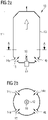
- FIGS 2a and 2b 12 show longitudinal and cross-sections through one embodiment of a portion of an electric gas heater 10 having a heating chamber 11 with a plasma torch 12.
- FIG. The plasma torch 12 is arranged in the center of the heating chamber 11 . This is made in cross-section along line AA Figure 2a in Figure 2b good to see.
- the cylindrical, round heating chamber in the example shown 11 is delimited by the longitudinal wall 13 of the heating chamber.
- Precursor gas is - shown as an arrow - introduced into the heating chamber 11 through the introduction openings 14a, 14b, 14c, 14d. Heated gas--represented by a block arrow--is discharged from the heating chamber 11 through a discharge opening, not shown separately--represented by an arrow.
- the precursor gas is introduced into the heating chamber 11 between the longitudinal wall 13 of the heating chamber and the plasma torch 12 .
- the flow of precursor gas 15 shown from the inlet opening 14a is thus located between the plasma 16 and the longitudinal wall 13 of the heating chamber.
- figure 3 12 shows a section through one embodiment of a portion of an electric gas heater 17 having a heating chamber 18 with a plasma torch 19.
- the heating chamber 18 is essentially cylindrical, with the plasma torch 19 lying essentially along the cylinder axis 20 .
- Precursor gas 22 is introduced tangentially into the heating chamber 18 through an introduction device 21 with an inlet opening and, after introduction, flows around the plasma torch 19 to the discharge opening 23.
- the cylinder axis 20 runs through the discharge opening 23 for discharging the heated gas.
- Several such heating chambers could also be used each with a plasma torch in the electric gas heating device.
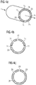
- FIGS. 4 a - i show variants of the arrangement of plasma torches in a heating chamber of a gas heating device, in which there are several plasma torches.
- possible arrangement forms are ring-shaped, semi-circular or part-circle arranged radially around the longitudinal axis of the heating chamber, which in the Figures 4a, 4b, 4c is shown.
- Figure 4a shows an oblique view in a section through a cylindrical heating chamber 24 perpendicular to the longitudinal axis - that of the flow direction of the gas to be heated, with arrows indicated corresponds to - how ring-shaped several openings 25 are present for mounting plasma torches.
- the longitudinal axis of the plasma burners can, for example, be perpendicular or inclined to the longitudinal axis of the heating chamber 24 .
- Figure 4b shows in a section through a cylindrical heating chamber 26 perpendicular to the longitudinal axis - which corresponds to the direction of flow of the gas to be heated - how semicircular several openings 27 are present for mounting plasma torches.
- Figure 4c shows in a section through a cylindrical heating chamber 28 perpendicular to the longitudinal axis - which corresponds to the direction of flow of the gas to be heated - how semicircular there are several openings 29 for mounting plasma torches.
- Figure 4d shows a longitudinal section through a section of a heating chamber as in FIG Figure 4a how to install multiple rings of plasma torches;
- the openings 25 for assembly, the longitudinal axis 30 of the heating chamber and the gas flow direction 31 are shown.
- Figure 4e shows this in a corresponding view for an arrangement in which there is only one plasma torch per position along the longitudinal axis.
- Figure 4f shows in a corresponding view an example of how the plasma torches can be oriented with respect to the longitudinal axis.
- the arrows indicate that the plasma torches are inclined to the longitudinal axis.
- Figures 4g and 4h show in to the Figure 4a largely analogous view that the plasma torches indicated by arrows can be aimed at the center of the gas flow - in Figure 4g shown -, or practically tangential to the gas flow - in Figure 4h shown.
- the directional vector of the entering plasma torch flow - the directions of the arrows in the Figures 4g and 4h corresponds - can therefore be at least partially axial and / or at least partially tangential to the flow of gas from the gas inlet port to the gas outlet port.
- Figure 4i is shown schematically in a section perpendicular to the longitudinal axis of a variant of a heating chamber 32, such as the gas flow 33 to be heated between the plasma torch 34 and wall of the heating chamber 32 is introduced.
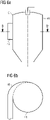
- Figure 5a shows a longitudinal section through a heating chamber 35, which includes a cylindrical part inlet part 36 with inlet opening 37 and a conical part outlet part 38 with outlet opening 39.
- the hydraulic diameter of the inlet opening 37 is 45% of the diameter of the inlet part.
- the ratio of the diameter of the inlet opening 37 to the radius of the inlet part 36 is 90%.
- the angle ⁇ of the heating chamber side wall of the discharge part to the longitudinal axis 40 is 35°.
- the plasma torch 41 is arranged centrally in the cover part 42, and a carrier gas line 43 for supplying carrier gas is also shown.
- the inlet opening is not symmetrical - ie asymmetrical - arranged to the longitudinal axis of the heating chamber.
- the flow of precursor gas that is introduced can flow in a spiral shape along the longitudinal wall of the heating chamber—in the inlet part and in the outlet part; the current is not introduced radially towards the longitudinal axis, but tangentially to the longitudinal wall of the heating chamber.
- Figure 5b shows a view of the in Figure 5a shown device from above. Analogous to Figure 5a outlines of variants of the inlet opening are also drawn in with dotted and dashed lines.
- Figure 6a and 6b show in to Figure 5a and 5b largely analogous views of an embodiment in which the introduction opening 45 on the introduction part 44 compared to Figure 5a is offset laterally.
- the gas flow to be heated is introduced into the cylindrical part, introduction part 44 spiral.
- FIG. 12 schematically shows, by means of a section along FF′, seen from above, how the inlet is drawn spirally around the cylindrical inlet part 44.
- FIG. The dashed line shows the outline of the edge C in the area where the inlet opening opens into the cylindrical inlet part.
- the helical portion could also extend less or more; it could also follow the shape of the entire lead-in portion of the spiral dictated by the lead-in 46.
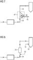
- figure 7 shows analogous to figure 1 , How in the electric gas heater 47 a plasma torch 48, whose plasma is generated with electrical energy using carrier gas from the carrier gas line 49, in the gas heater 47 the precursor gas reformer gas in the precursor gas line 50 is heated. The electrical energy is introduced into the precursor gas by means of a plasma.
- figure 8 shows largely analogous to figure 1 an embodiment of a device according to the invention, in which an additional reducing gas line 51 for introducing additional reducing gas into the reduction unit 52 is present.
- the optional addition of natural gas 53 to the precursor gas line 54 upstream of the electric gas heating device 55 is also shown in dashed lines.
- a precursor gas which is a mixture of natural gas 53 and reformer gas, is heated; this precursor gas is based on reformer gas.
Landscapes
- Engineering & Computer Science (AREA)
- Chemical & Material Sciences (AREA)
- Manufacturing & Machinery (AREA)
- Materials Engineering (AREA)
- Metallurgy (AREA)
- Organic Chemistry (AREA)
- Hydrogen, Water And Hydrids (AREA)
- Manufacture Of Iron (AREA)
- Manufacture And Refinement Of Metals (AREA)
Claims (19)
- Procédé destiné à la réduction directe d'oxydes métalliques (2) en utilisant un gaz de réduction qui se base sur au minimum un gaz faisant office de précurseur ; dans lequel au moins un gaz (15, 22) faisant office de précurseur se base sur un gaz qui a été soumis à un reformage, que l'on obtient par l'intermédiaire d'un reformage catalytique d'un gaz (4) qui contient des hydrocarbures, dans un reformeur (3),
caractérisé en ce que,au cours de la préparation du gaz de réduction, on chauffe au moins un gaz faisant office de précurseur qui se base sur un gaz qui a été soumis à un reformage, de manière facultative en outre également sur un ou plusieurs gaz supplémentaire (s) faisant office de précurseur(s), en faisant appel à de l'énergie électrique ;dans lequel on introduit au moins une quantité partielle de l'énergie électrique au moyen d'un plasma (16) dans le gaz (15, 22) faisant office de précurseur. - Procédé selon la revendication 1, caractérisé en ce que le gaz faisant office de précurseur qui se base sur un gaz qui a été soumis à un reformage est chauffé par l'énergie électrique à une température qui se situe dans une plage allant jusqu'à 200 °C au-delà de sa température de sortie à partir du reformeur.
- Procédé selon l'une quelconque des revendications 1 à 2, caractérisé en ce que l'on chauffe le gaz (15, 22) faisant office de précurseur qui est prévu pour le chauffage électrique, avant le chauffage en faisant appel à de l'énergie électrique, déjà d'une autre manière, de préférence à au moins 700 °C, de manière particulièrement préférée à au moins 750 °C.
- Procédé selon l'une quelconque des revendications 1 à 3, caractérisé en ce que l'on chauffe le gaz (15, 22) faisant office de précurseur qui est prévu pour le chauffage électrique, en faisant appel à de l'énergie électrique à une température supérieure à 800 °C, de préférence à une température supérieure à 900 °C.
- Procédé selon l'une quelconque des revendications 1 à 4, caractérisé en ce que la température du gaz de réduction, au cours de son introduction dans une installation de réduction (9) qui contient les oxydes métalliques qui font l'objet d'une réduction, s'élève à une valeur au moins supérieure à 800 °C, de préférence au moins supérieure à 900 °C, de manière particulièrement préférée s'élève à au moins 940 °C, et jusqu'à une température de 1100 °C, de préférence jusqu'à 1050 °C, de manière particulièrement préférée jusqu'à 1000 °C.
- Procédé selon l'une quelconque des revendications 1 à 5, caractérisé en ce que l'on ajoute un gaz supplémentaire qui contient des hydrocarbures à un gaz (15, 22) faisant office de précurseur, que l'on chauffe en faisant appel à de l'énergie électrique, avant et/ou pendant et/ou après son chauffage en faisant appel à de l'énergie électrique.
- Procédé selon l'une quelconque des revendications 1 à 6, caractérisé en ce que l'on soumet à un reformage in situ au moins une quantité partielle du gaz supplémentaire qui contient des hydrocarbures, avant d'introduire le gaz de réduction dans une installation de réduction (9) qui contient les oxydes métalliques (2).
- Procédé selon l'une quelconque des revendications 1 à 7, caractérisé en ce que l'on soumet à un reformage in situ au moins une quantité partielle d'un gaz faisant office de précurseur, qui contient des hydrocarbures, avant d'introduire le gaz de réduction dans une installation de réduction (9) qui contient les oxydes métalliques (2).
- Procédé selon l'une quelconque des revendications 1 à 8, caractérisé en ce que l'on utilise, pour la réduction directe des oxydes métalliques (2), au moins un gaz de réduction supplémentaire.
- Dispositif destiné à la réduction directe (1) d'oxydes métalliques (2) en faisant appel à un gaz de réduction,qui comprendun reformeur catalytique (3) qui est destiné à la préparation d'un gaz qui a été soumis à un reformage ;un conduit (5) pour le gaz qui a été soumis à un reformage, destiné à l'évacuation du gaz qui a été soumis à un reformage à l'extérieur du reformeur catalytique (3) ;une installation de réduction (9) ;un conduit (8) pour le gaz de réduction, destiné à l'introduction du gaz de réduction dans l'installation de réduction (9) ;caractérisé en ce quele dispositif comprend au moins un conduit (6) pour le gaz faisant office de précurseur ;et au moins un conduit (6) pour le gaz faisant office de précurseur comprend un dispositif électrique (7, 10, 17) pour le chauffage du gaz ;et au moins un conduit (6) pour le gaz faisant office de précurseur émane du conduit (5) destiné au gaz qui a été soumis à un reformage ;dans lequel au moins un conduit pour le gaz faisant office de précurseur qui émane du conduit pour le gaz qui a été soumis à un reformage comprend un dispositif électrique pour le chauffage du gaz ;et dans lequel chaque conduit (6) pour le gaz faisant office de précurseur débouche dans le conduit (8) pour le gaz de réduction ;et dans lequel le dispositif électrique (10) pour le chauffage du gaz comprend au moins deux brûleurs à plasma, de manière tout particulièrement préférée au moins trois brûleurs à plasma.
- Dispositif selon la revendication 10, caractérisé en ce que le dispositif destiné à la réduction directe (1) comprend au moins un conduit (35) pour le gaz de réduction supplémentaire, qui est destiné à l'introduction du gaz de réduction supplémentaire dans l'installation de réduction (9).
- Dispositif selon l'une quelconque des revendications 10 à 12, caractérisé en ce que le dispositif électrique (10) pour le chauffage du gaz comprend au moins une chambre de chauffe (11) qui comprend un brûleur à plasma (12), au moins une ouverture d'évacuation destinée à l'évacuation du gaz chauffé et au moins une ouverture d'introduction (14a, 14b) destinée à l'introduction du gaz (15) faisant office de précurseur, et qui comprend au moins une paroi longitudinale (13) de chambre de chauffe, lorsqu'on regarde dans l'étendue longitudinale depuis l'ouverture d'introduction jusqu'à l'ouverture d'évacuation ; dans lequel le brûleur à plasma (12) est monté en position centrale dans la chambre de chauffe (11) ; et dans lequel l'ouverture d'introduction (14a, 14b) est disposée entre le brûleur à plasma (12) et la paroi longitudinale (13) de la chambre de chauffe.
- Dispositif selon l'une quelconque des revendications 10 à 13, caractérisé en ce que le dispositif électrique (17) pour le chauffage du gaz comprend au moins une chambre de chauffe (18) qui comprend un brûleur à plasma (19), au moins une ouverture d'évacuation (23) destinée à l'évacuation du gaz chauffé et au moins une ouverture d'introduction destinée à l'introduction du gaz (22) faisant office de précurseur, et au moins une paroi longitudinale de chambre de chauffe, lorsqu'on regarde dans l'étendue longitudinale depuis l'ouverture d'introduction jusqu'à l'ouverture d'évacuation (23) ; dans lequel l'ouverture d'introduction est disposée et la chambre de chauffe (18) est configurée d'une manière telle qu'un courant, du gaz (22) faisant office de précurseur, qui a été introduit s'écoule en formant une spirale tout autour du brûleur à plasma (19) entre le brûleur à plasma (19) et la paroi longitudinale de la chambre de chauffe depuis l'ouverture d'introduction jusqu'à l'ouverture d'évacuation (23).
- Dispositif selon la revendication 14, caractérisé en ce que l'ouverture d'introduction est disposée de manière asymétrique par rapport à l'axe longitudinal de la chambre de chauffe et est appropriée pour guider le gaz faisant office de précurseur, dans une direction tangentielle par rapport à la paroi longitudinale de la chambre de chauffe, jusque dans la chambre de chauffe.
- Dispositif selon la revendication 14 ou 15, caractérisé en ce que le diamètre hydraulique de l'ouverture d'introduction se situe dans la plage de 25 % à 75 % du diamètre hydraulique de la chambre de chauffe.
- Dispositif selon la revendication 14 ou 15, caractérisé en ce que la chambre de chauffe comprend une partie de forme cylindrique faisant office d'introduction qui comprend une ouverture d'introduction et une partie de forme conique faisant office d'évacuation qui comprend une ouverture d'évacuation, et le diamètre hydraulique de l'ouverture d'introduction se situe dans la plage de 25 % à 75 % du diamètre de la partie faisant office d'introduction.
- Dispositif selon l'une quelconque des revendications 13, 14, 16, caractérisé en ce que la chambre de chauffe comprend une partie de forme cylindrique faisant office d'introduction qui comprend une ouverture d'introduction et une partie de forme conique faisant office d'évacuation qui comprend une ouverture d'évacuation ; dans lequel le rapport entre la hauteur de la partie faisant office d'introduction et le diamètre de la partie faisant office d'introduction se situe dans la plage de 1 à 10, de préférence de 1 à 5, de manière particulièrement préférée de 1 à 2,5.
- Dispositif selon l'une quelconque des revendications 13, 14, 16, 17, caractérisé en ce que la chambre de chauffe comprend une partie de forme cylindrique faisant office d'introduction qui comprend une ouverture d'introduction et une partie de forme conique faisant office d'évacuation qui comprend une ouverture d'évacuation ; dans lequel l'angle formé par la paroi latérale de chambre de chauffe de la partie faisant office d'évacuation par rapport à l'axe longitudinal se situe dans la plage de 5° à 45°.
- Dispositif selon l'une quelconque des revendications 10 à 18, caractérisé en ce que le dispositif (7, 10, 17)pour le chauffage du gaz comprend au moins une chambre de chauffe dans laquelle sont présents plusieurs brûleurs à plasma.
Applications Claiming Priority (2)
| Application Number | Priority Date | Filing Date | Title |
|---|---|---|---|
| EP18213141.7A EP3670676A1 (fr) | 2018-12-17 | 2018-12-17 | Procédé et dispositif de réduction directe à l'aide d'un gaz de réduction chauffé électriquement |
| PCT/EP2019/085350 WO2020127049A1 (fr) | 2018-12-17 | 2019-12-16 | Procédé et dispositif de réduction directe par un gaz réducteur chauffé par voie électrique |
Publications (2)
| Publication Number | Publication Date |
|---|---|
| EP3899057A1 EP3899057A1 (fr) | 2021-10-27 |
| EP3899057B1 true EP3899057B1 (fr) | 2022-12-14 |
Family
ID=64744482
Family Applications (2)
| Application Number | Title | Priority Date | Filing Date |
|---|---|---|---|
| EP18213141.7A Withdrawn EP3670676A1 (fr) | 2018-12-17 | 2018-12-17 | Procédé et dispositif de réduction directe à l'aide d'un gaz de réduction chauffé électriquement |
| EP19827679.2A Active EP3899057B1 (fr) | 2018-12-17 | 2019-12-16 | Procédé et dispositif de réduction directe à l'aide d'un gaz de réduction chauffé électriquement |
Family Applications Before (1)
| Application Number | Title | Priority Date | Filing Date |
|---|---|---|---|
| EP18213141.7A Withdrawn EP3670676A1 (fr) | 2018-12-17 | 2018-12-17 | Procédé et dispositif de réduction directe à l'aide d'un gaz de réduction chauffé électriquement |
Country Status (8)
| Country | Link |
|---|---|
| US (1) | US12209293B2 (fr) |
| EP (2) | EP3670676A1 (fr) |
| CA (1) | CA3121597A1 (fr) |
| ES (1) | ES2940209T3 (fr) |
| MX (1) | MX2021006611A (fr) |
| RU (1) | RU2771127C1 (fr) |
| SA (1) | SA521422308B1 (fr) |
| WO (1) | WO2020127049A1 (fr) |
Families Citing this family (3)
| Publication number | Priority date | Publication date | Assignee | Title |
|---|---|---|---|---|
| CN115896378B (zh) * | 2022-10-24 | 2023-05-23 | 中国科学院过程工程研究所 | 一种电能加热的氢气直接还原炼铁方法 |
| EP4379069A1 (fr) * | 2022-11-30 | 2024-06-05 | Primetals Technologies Austria GmbH | Réduction de lit fluidisé à base d'hydrogène |
| CN116837162B (zh) * | 2023-06-07 | 2025-11-25 | 北京科技大学 | 基于等离子加热生产金属化球团的系统及方法 |
Family Cites Families (11)
| Publication number | Priority date | Publication date | Assignee | Title |
|---|---|---|---|---|
| SE388210B (sv) | 1973-01-26 | 1976-09-27 | Skf Svenska Kullagerfab Ab | Sett vid reduktion av metall ur metalloxider |
| SE434408B (sv) | 1980-09-17 | 1984-07-23 | Asea Ab | Anordning for reduktion av metalloxid |
| US5997596A (en) | 1997-09-05 | 1999-12-07 | Spectrum Design & Consulting International, Inc. | Oxygen-fuel boost reformer process and apparatus |
| US6478841B1 (en) | 2001-09-12 | 2002-11-12 | Techint Technologies Inc. | Integrated mini-mill for iron and steel making |
| EP1641945B1 (fr) * | 2003-05-15 | 2018-12-12 | HYLSA, S.A. de C.V. | Procede et appareil pour ameliorer l'utilisation de sources d'energie primaire dans des usines siderurgiques integrees |
| WO2005080609A1 (fr) | 2004-02-23 | 2005-09-01 | Anatoly Timofeevich Neklesa | Procede de fabrication de fer par sa reduction directe et dispositif correspondant |
| BE1016305A6 (fr) * | 2004-11-10 | 2006-07-04 | Allard Georges | Procede de production d'eponges de fer a partir de fines de minerais. |
| US20070084116A1 (en) | 2005-10-13 | 2007-04-19 | Bayerische Motoren Werke Aktiengesellschaft | Reformer system having electrical heating devices |
| WO2014040989A2 (fr) | 2012-09-14 | 2014-03-20 | Voestalpine Stahl Gmbh | Procédé de production d'acier |
| DE102016122083A1 (de) | 2016-11-17 | 2018-05-17 | Salzgitter Flachstahl Gmbh | Verfahren und Vorrichtung zum Betreiben eines Direktreduktionsreaktors zur Herstellung von direkt reduziertem Eisen aus Eisenerz |
| CN207567268U (zh) * | 2017-08-31 | 2018-07-03 | 江苏省冶金设计院有限公司 | 用于气基竖炉直接还原系统的还原气的加热系统 |
-
2018
- 2018-12-17 EP EP18213141.7A patent/EP3670676A1/fr not_active Withdrawn
-
2019
- 2019-12-16 RU RU2021120201A patent/RU2771127C1/ru active
- 2019-12-16 MX MX2021006611A patent/MX2021006611A/es unknown
- 2019-12-16 ES ES19827679T patent/ES2940209T3/es active Active
- 2019-12-16 EP EP19827679.2A patent/EP3899057B1/fr active Active
- 2019-12-16 CA CA3121597A patent/CA3121597A1/fr active Pending
- 2019-12-16 US US17/414,368 patent/US12209293B2/en active Active
- 2019-12-16 WO PCT/EP2019/085350 patent/WO2020127049A1/fr not_active Ceased
-
2021
- 2021-06-17 SA SA521422308A patent/SA521422308B1/ar unknown
Also Published As
| Publication number | Publication date |
|---|---|
| US20220074006A1 (en) | 2022-03-10 |
| ES2940209T3 (es) | 2023-05-04 |
| EP3899057A1 (fr) | 2021-10-27 |
| MX2021006611A (es) | 2021-07-07 |
| EP3670676A1 (fr) | 2020-06-24 |
| RU2771127C1 (ru) | 2022-04-26 |
| US12209293B2 (en) | 2025-01-28 |
| SA521422308B1 (ar) | 2024-01-09 |
| CA3121597A1 (fr) | 2020-06-25 |
| WO2020127049A1 (fr) | 2020-06-25 |
Similar Documents
| Publication | Publication Date | Title |
|---|---|---|
| EP3008218B1 (fr) | Haut fourneau et procédé servant à faire fonctionner un haut fourneau | |
| EP0157758B1 (fr) | Procédé pour la production de gaz synthétiques, en particulier de gaz de réduction ainsi que dispositif pour la mise en oeuvre de ce procédé | |
| DE1417796C3 (de) | Verfahren zur Herstellung eines wasserstoffreichen Gases | |
| EP3212566B1 (fr) | Procédé et installation de production de gaz de synthèse | |
| EP2729404A2 (fr) | Procédé de production parallèle d'hydrogène et de produits à base de carbone | |
| AT510955B1 (de) | Reduktion von metalloxiden unter verwendung eines sowohl kohlenwasserstoff als auch wasserstoff enthaltenden gasstromes | |
| EP3172164B1 (fr) | Procédé pour la préparation d'hydrogène | |
| EP3383976A1 (fr) | Procédé de production de gaz de synthèse | |
| EP3899057A1 (fr) | Procédé et dispositif de réduction directe par un gaz réducteur chauffé par voie électrique | |
| EP3194333A1 (fr) | Procédé de production de gaz de synthèse | |
| WO2021094464A1 (fr) | Procédé et dispositif de production d'hydrogène et de carbone pyrolytique à partir d'hydrocarbures | |
| EP0920352A2 (fr) | Appareil et procede pour effectuer des reactions dans des couches de particules fluidisees | |
| DE102015015968A1 (de) | Verfahren zur Erzeugung von Synthesegas | |
| WO2024027948A1 (fr) | Procédé et installation pour la mise en œuvre d'une réaction en phase gazeuse | |
| LU103152B1 (de) | Chemieanlage und Verfahren zur Hydrodesulfurierung eines kohlenwasserstoff- und schwefelhaltigen Einsatzstoffstroms | |
| DD202052A5 (de) | Verfahren und vorrichtung zur reduktion von metallerzen | |
| EP4549595A1 (fr) | Réduction de matériau contenant de l'oxyde métallique à base d'ammoniac nh3 et de gaz contenant du carbone | |
| EP4461701A1 (fr) | Procédé et installation de production d'un ou plusieurs produits de traitement | |
| EP4585558A1 (fr) | Procédé et installation de fabrication d'un produit de processus | |
| EP4455313A1 (fr) | Procédé pour réduire le support de minerai de fer dans l'éponge de fer | |
| EP4379069A1 (fr) | Réduction de lit fluidisé à base d'hydrogène | |
| EP4731729A1 (fr) | Installation chimique et procédé d'hydrodésulfuration d'un courant de charge d'alimentation contenant des hydrocarbures et du soufre | |
| WO2025093545A1 (fr) | Réduction d'un matériau contenant de l'oxyde métallique sur la base d'ammoniac nh3 et de gaz contenant du carbone | |
| DE102023116010A1 (de) | Chemieanlage und Verfahren zur Hydrodesulfurierung eines kohlenwasserstoff- und schwefelhaltigen Einsatzstoffstroms | |
| WO2026037794A1 (fr) | Production d'une éponge de fer nitrurée |
Legal Events
| Date | Code | Title | Description |
|---|---|---|---|
| STAA | Information on the status of an ep patent application or granted ep patent |
Free format text: STATUS: UNKNOWN |
|
| STAA | Information on the status of an ep patent application or granted ep patent |
Free format text: STATUS: THE INTERNATIONAL PUBLICATION HAS BEEN MADE |
|
| PUAI | Public reference made under article 153(3) epc to a published international application that has entered the european phase |
Free format text: ORIGINAL CODE: 0009012 |
|
| STAA | Information on the status of an ep patent application or granted ep patent |
Free format text: STATUS: REQUEST FOR EXAMINATION WAS MADE |
|
| 17P | Request for examination filed |
Effective date: 20210719 |
|
| AK | Designated contracting states |
Kind code of ref document: A1 Designated state(s): AL AT BE BG CH CY CZ DE DK EE ES FI FR GB GR HR HU IE IS IT LI LT LU LV MC MK MT NL NO PL PT RO RS SE SI SK SM TR |
|
| DAV | Request for validation of the european patent (deleted) | ||
| DAX | Request for extension of the european patent (deleted) | ||
| GRAP | Despatch of communication of intention to grant a patent |
Free format text: ORIGINAL CODE: EPIDOSNIGR1 |
|
| STAA | Information on the status of an ep patent application or granted ep patent |
Free format text: STATUS: GRANT OF PATENT IS INTENDED |
|
| INTG | Intention to grant announced |
Effective date: 20220722 |
|
| GRAS | Grant fee paid |
Free format text: ORIGINAL CODE: EPIDOSNIGR3 |
|
| GRAA | (expected) grant |
Free format text: ORIGINAL CODE: 0009210 |
|
| STAA | Information on the status of an ep patent application or granted ep patent |
Free format text: STATUS: THE PATENT HAS BEEN GRANTED |
|
| AK | Designated contracting states |
Kind code of ref document: B1 Designated state(s): AL AT BE BG CH CY CZ DE DK EE ES FI FR GB GR HR HU IE IS IT LI LT LU LV MC MK MT NL NO PL PT RO RS SE SI SK SM TR |
|
| REG | Reference to a national code |
Ref country code: GB Ref legal event code: FG4D Free format text: NOT ENGLISH |
|
| REG | Reference to a national code |
Ref country code: CH Ref legal event code: EP |
|
| REG | Reference to a national code |
Ref country code: DE Ref legal event code: R096 Ref document number: 502019006546 Country of ref document: DE |
|
| REG | Reference to a national code |
Ref country code: IE Ref legal event code: FG4D Free format text: LANGUAGE OF EP DOCUMENT: GERMAN |
|
| REG | Reference to a national code |
Ref country code: AT Ref legal event code: REF Ref document number: 1537692 Country of ref document: AT Kind code of ref document: T Effective date: 20230115 |
|
| REG | Reference to a national code |
Ref country code: SE Ref legal event code: TRGR |
|
| REG | Reference to a national code |
Ref country code: NL Ref legal event code: FP |
|
| REG | Reference to a national code |
Ref country code: NO Ref legal event code: T2 Effective date: 20221214 |
|
| REG | Reference to a national code |
Ref country code: LT Ref legal event code: MG9D |
|
| PG25 | Lapsed in a contracting state [announced via postgrant information from national office to epo] |
Ref country code: LT Free format text: LAPSE BECAUSE OF FAILURE TO SUBMIT A TRANSLATION OF THE DESCRIPTION OR TO PAY THE FEE WITHIN THE PRESCRIBED TIME-LIMIT Effective date: 20221214 Ref country code: FI Free format text: LAPSE BECAUSE OF FAILURE TO SUBMIT A TRANSLATION OF THE DESCRIPTION OR TO PAY THE FEE WITHIN THE PRESCRIBED TIME-LIMIT Effective date: 20221214 |
|
| REG | Reference to a national code |
Ref country code: ES Ref legal event code: FG2A Ref document number: 2940209 Country of ref document: ES Kind code of ref document: T3 Effective date: 20230504 |
|
| PG25 | Lapsed in a contracting state [announced via postgrant information from national office to epo] |
Ref country code: RS Free format text: LAPSE BECAUSE OF FAILURE TO SUBMIT A TRANSLATION OF THE DESCRIPTION OR TO PAY THE FEE WITHIN THE PRESCRIBED TIME-LIMIT Effective date: 20221214 Ref country code: LV Free format text: LAPSE BECAUSE OF FAILURE TO SUBMIT A TRANSLATION OF THE DESCRIPTION OR TO PAY THE FEE WITHIN THE PRESCRIBED TIME-LIMIT Effective date: 20221214 Ref country code: HR Free format text: LAPSE BECAUSE OF FAILURE TO SUBMIT A TRANSLATION OF THE DESCRIPTION OR TO PAY THE FEE WITHIN THE PRESCRIBED TIME-LIMIT Effective date: 20221214 Ref country code: GR Free format text: LAPSE BECAUSE OF FAILURE TO SUBMIT A TRANSLATION OF THE DESCRIPTION OR TO PAY THE FEE WITHIN THE PRESCRIBED TIME-LIMIT Effective date: 20230315 |
|
| PG25 | Lapsed in a contracting state [announced via postgrant information from national office to epo] |
Ref country code: SM Free format text: LAPSE BECAUSE OF FAILURE TO SUBMIT A TRANSLATION OF THE DESCRIPTION OR TO PAY THE FEE WITHIN THE PRESCRIBED TIME-LIMIT Effective date: 20221214 Ref country code: RO Free format text: LAPSE BECAUSE OF FAILURE TO SUBMIT A TRANSLATION OF THE DESCRIPTION OR TO PAY THE FEE WITHIN THE PRESCRIBED TIME-LIMIT Effective date: 20221214 Ref country code: PT Free format text: LAPSE BECAUSE OF FAILURE TO SUBMIT A TRANSLATION OF THE DESCRIPTION OR TO PAY THE FEE WITHIN THE PRESCRIBED TIME-LIMIT Effective date: 20230414 Ref country code: IT Free format text: LAPSE BECAUSE OF NON-PAYMENT OF DUE FEES Effective date: 20221216 Ref country code: EE Free format text: LAPSE BECAUSE OF FAILURE TO SUBMIT A TRANSLATION OF THE DESCRIPTION OR TO PAY THE FEE WITHIN THE PRESCRIBED TIME-LIMIT Effective date: 20221214 Ref country code: CZ Free format text: LAPSE BECAUSE OF FAILURE TO SUBMIT A TRANSLATION OF THE DESCRIPTION OR TO PAY THE FEE WITHIN THE PRESCRIBED TIME-LIMIT Effective date: 20221214 |
|
| REG | Reference to a national code |
Ref country code: CH Ref legal event code: PL |
|
| REG | Reference to a national code |
Ref country code: BE Ref legal event code: MM Effective date: 20221231 |
|
| PG25 | Lapsed in a contracting state [announced via postgrant information from national office to epo] |
Ref country code: SK Free format text: LAPSE BECAUSE OF FAILURE TO SUBMIT A TRANSLATION OF THE DESCRIPTION OR TO PAY THE FEE WITHIN THE PRESCRIBED TIME-LIMIT Effective date: 20221214 Ref country code: PL Free format text: LAPSE BECAUSE OF FAILURE TO SUBMIT A TRANSLATION OF THE DESCRIPTION OR TO PAY THE FEE WITHIN THE PRESCRIBED TIME-LIMIT Effective date: 20221214 Ref country code: LU Free format text: LAPSE BECAUSE OF NON-PAYMENT OF DUE FEES Effective date: 20221216 Ref country code: IS Free format text: LAPSE BECAUSE OF FAILURE TO SUBMIT A TRANSLATION OF THE DESCRIPTION OR TO PAY THE FEE WITHIN THE PRESCRIBED TIME-LIMIT Effective date: 20230414 Ref country code: AL Free format text: LAPSE BECAUSE OF FAILURE TO SUBMIT A TRANSLATION OF THE DESCRIPTION OR TO PAY THE FEE WITHIN THE PRESCRIBED TIME-LIMIT Effective date: 20221214 |
|
| REG | Reference to a national code |
Ref country code: DE Ref legal event code: R097 Ref document number: 502019006546 Country of ref document: DE |
|
| PG25 | Lapsed in a contracting state [announced via postgrant information from national office to epo] |
Ref country code: MC Free format text: LAPSE BECAUSE OF FAILURE TO SUBMIT A TRANSLATION OF THE DESCRIPTION OR TO PAY THE FEE WITHIN THE PRESCRIBED TIME-LIMIT Effective date: 20221214 |
|
| PLBE | No opposition filed within time limit |
Free format text: ORIGINAL CODE: 0009261 |
|
| STAA | Information on the status of an ep patent application or granted ep patent |
Free format text: STATUS: NO OPPOSITION FILED WITHIN TIME LIMIT |
|
| PG25 | Lapsed in a contracting state [announced via postgrant information from national office to epo] |
Ref country code: LI Free format text: LAPSE BECAUSE OF NON-PAYMENT OF DUE FEES Effective date: 20221231 Ref country code: IE Free format text: LAPSE BECAUSE OF NON-PAYMENT OF DUE FEES Effective date: 20221216 Ref country code: DK Free format text: LAPSE BECAUSE OF FAILURE TO SUBMIT A TRANSLATION OF THE DESCRIPTION OR TO PAY THE FEE WITHIN THE PRESCRIBED TIME-LIMIT Effective date: 20221214 Ref country code: CH Free format text: LAPSE BECAUSE OF NON-PAYMENT OF DUE FEES Effective date: 20221231 |
|
| 26N | No opposition filed |
Effective date: 20230915 |
|
| PG25 | Lapsed in a contracting state [announced via postgrant information from national office to epo] |
Ref country code: SI Free format text: LAPSE BECAUSE OF FAILURE TO SUBMIT A TRANSLATION OF THE DESCRIPTION OR TO PAY THE FEE WITHIN THE PRESCRIBED TIME-LIMIT Effective date: 20221214 Ref country code: BE Free format text: LAPSE BECAUSE OF NON-PAYMENT OF DUE FEES Effective date: 20221231 |
|
| PG25 | Lapsed in a contracting state [announced via postgrant information from national office to epo] |
Ref country code: IT Free format text: LAPSE BECAUSE OF NON-PAYMENT OF DUE FEES Effective date: 20221216 |
|
| PGRI | Patent reinstated in contracting state [announced from national office to epo] |
Ref country code: IT Effective date: 20221231 |
|
| PG25 | Lapsed in a contracting state [announced via postgrant information from national office to epo] |
Ref country code: CY Free format text: LAPSE BECAUSE OF FAILURE TO SUBMIT A TRANSLATION OF THE DESCRIPTION OR TO PAY THE FEE WITHIN THE PRESCRIBED TIME-LIMIT Effective date: 20221214 |
|
| PG25 | Lapsed in a contracting state [announced via postgrant information from national office to epo] |
Ref country code: MK Free format text: LAPSE BECAUSE OF FAILURE TO SUBMIT A TRANSLATION OF THE DESCRIPTION OR TO PAY THE FEE WITHIN THE PRESCRIBED TIME-LIMIT Effective date: 20221214 Ref country code: HU Free format text: LAPSE BECAUSE OF FAILURE TO SUBMIT A TRANSLATION OF THE DESCRIPTION OR TO PAY THE FEE WITHIN THE PRESCRIBED TIME-LIMIT; INVALID AB INITIO Effective date: 20191216 |
|
| PG25 | Lapsed in a contracting state [announced via postgrant information from national office to epo] |
Ref country code: BG Free format text: LAPSE BECAUSE OF FAILURE TO SUBMIT A TRANSLATION OF THE DESCRIPTION OR TO PAY THE FEE WITHIN THE PRESCRIBED TIME-LIMIT Effective date: 20221214 |
|
| GBPC | Gb: european patent ceased through non-payment of renewal fee |
Effective date: 20231216 |
|
| PG25 | Lapsed in a contracting state [announced via postgrant information from national office to epo] |
Ref country code: MT Free format text: LAPSE BECAUSE OF FAILURE TO SUBMIT A TRANSLATION OF THE DESCRIPTION OR TO PAY THE FEE WITHIN THE PRESCRIBED TIME-LIMIT Effective date: 20221214 |
|
| PG25 | Lapsed in a contracting state [announced via postgrant information from national office to epo] |
Ref country code: GB Free format text: LAPSE BECAUSE OF NON-PAYMENT OF DUE FEES Effective date: 20231216 |
|
| PG25 | Lapsed in a contracting state [announced via postgrant information from national office to epo] |
Ref country code: GB Free format text: LAPSE BECAUSE OF NON-PAYMENT OF DUE FEES Effective date: 20231216 |
|
| PG25 | Lapsed in a contracting state [announced via postgrant information from national office to epo] |
Ref country code: TR Free format text: LAPSE BECAUSE OF FAILURE TO SUBMIT A TRANSLATION OF THE DESCRIPTION OR TO PAY THE FEE WITHIN THE PRESCRIBED TIME-LIMIT Effective date: 20221214 |
|
| PGFP | Annual fee paid to national office [announced via postgrant information from national office to epo] |
Ref country code: DE Payment date: 20251211 Year of fee payment: 7 |
|
| PGFP | Annual fee paid to national office [announced via postgrant information from national office to epo] |
Ref country code: AT Payment date: 20251222 Year of fee payment: 7 |
|
| PGFP | Annual fee paid to national office [announced via postgrant information from national office to epo] |
Ref country code: IT Payment date: 20251223 Year of fee payment: 7 |
|
| PGFP | Annual fee paid to national office [announced via postgrant information from national office to epo] |
Ref country code: NL Payment date: 20251219 Year of fee payment: 7 Ref country code: FR Payment date: 20251229 Year of fee payment: 7 |
|
| PGFP | Annual fee paid to national office [announced via postgrant information from national office to epo] |
Ref country code: SE Payment date: 20251219 Year of fee payment: 7 |
|
| PGFP | Annual fee paid to national office [announced via postgrant information from national office to epo] |
Ref country code: ES Payment date: 20260130 Year of fee payment: 7 |
|
| PGFP | Annual fee paid to national office [announced via postgrant information from national office to epo] |
Ref country code: NO Payment date: 20251230 Year of fee payment: 7 |