EP3899224B1 - Dispositif de refroidissement d'un turbocompresseur d'un moteur hybride - Google Patents
Dispositif de refroidissement d'un turbocompresseur d'un moteur hybride Download PDFInfo
- Publication number
- EP3899224B1 EP3899224B1 EP19823800.8A EP19823800A EP3899224B1 EP 3899224 B1 EP3899224 B1 EP 3899224B1 EP 19823800 A EP19823800 A EP 19823800A EP 3899224 B1 EP3899224 B1 EP 3899224B1
- Authority
- EP
- European Patent Office
- Prior art keywords
- engine
- temperature
- turbocharger
- automatic
- shutdown
- Prior art date
- Legal status (The legal status is an assumption and is not a legal conclusion. Google has not performed a legal analysis and makes no representation as to the accuracy of the status listed.)
- Active
Links
Images
Classifications
-
- F—MECHANICAL ENGINEERING; LIGHTING; HEATING; WEAPONS; BLASTING
- F01—MACHINES OR ENGINES IN GENERAL; ENGINE PLANTS IN GENERAL; STEAM ENGINES
- F01P—COOLING OF MACHINES OR ENGINES IN GENERAL; COOLING OF INTERNAL-COMBUSTION ENGINES
- F01P3/00—Liquid cooling
- F01P3/20—Cooling circuits not specific to a single part of engine or machine
-
- F—MECHANICAL ENGINEERING; LIGHTING; HEATING; WEAPONS; BLASTING
- F02—COMBUSTION ENGINES; HOT-GAS OR COMBUSTION-PRODUCT ENGINE PLANTS
- F02B—INTERNAL-COMBUSTION PISTON ENGINES; COMBUSTION ENGINES IN GENERAL
- F02B39/00—Component parts, details, or accessories relating to, driven charging or scavenging pumps, not provided for in groups F02B33/00 - F02B37/00
- F02B39/005—Cooling of pump drives
-
- F—MECHANICAL ENGINEERING; LIGHTING; HEATING; WEAPONS; BLASTING
- F02—COMBUSTION ENGINES; HOT-GAS OR COMBUSTION-PRODUCT ENGINE PLANTS
- F02B—INTERNAL-COMBUSTION PISTON ENGINES; COMBUSTION ENGINES IN GENERAL
- F02B77/00—Component parts, details or accessories, not otherwise provided for
- F02B77/04—Cleaning of, preventing corrosion or erosion in, or preventing unwanted deposits in, combustion engines
-
- F—MECHANICAL ENGINEERING; LIGHTING; HEATING; WEAPONS; BLASTING
- F02—COMBUSTION ENGINES; HOT-GAS OR COMBUSTION-PRODUCT ENGINE PLANTS
- F02N—STARTING OF COMBUSTION ENGINES; STARTING AIDS FOR SUCH ENGINES, NOT OTHERWISE PROVIDED FOR
- F02N11/00—Starting of engines by means of electric motors
- F02N11/08—Circuits specially adapted for starting of engines
- F02N11/0814—Circuits specially adapted for starting of engines comprising means for controlling automatic idle-start-stop
-
- F—MECHANICAL ENGINEERING; LIGHTING; HEATING; WEAPONS; BLASTING
- F01—MACHINES OR ENGINES IN GENERAL; ENGINE PLANTS IN GENERAL; STEAM ENGINES
- F01P—COOLING OF MACHINES OR ENGINES IN GENERAL; COOLING OF INTERNAL-COMBUSTION ENGINES
- F01P2031/00—Fail safe
- F01P2031/30—Cooling after the engine is stopped
-
- F—MECHANICAL ENGINEERING; LIGHTING; HEATING; WEAPONS; BLASTING
- F01—MACHINES OR ENGINES IN GENERAL; ENGINE PLANTS IN GENERAL; STEAM ENGINES
- F01P—COOLING OF MACHINES OR ENGINES IN GENERAL; COOLING OF INTERNAL-COMBUSTION ENGINES
- F01P2060/00—Cooling circuits using auxiliaries
- F01P2060/12—Turbo charger
-
- F—MECHANICAL ENGINEERING; LIGHTING; HEATING; WEAPONS; BLASTING
- F02—COMBUSTION ENGINES; HOT-GAS OR COMBUSTION-PRODUCT ENGINE PLANTS
- F02B—INTERNAL-COMBUSTION PISTON ENGINES; COMBUSTION ENGINES IN GENERAL
- F02B39/00—Component parts, details, or accessories relating to, driven charging or scavenging pumps, not provided for in groups F02B33/00 - F02B37/00
- F02B39/16—Other safety measures for, or other control of, pumps
- F02B2039/162—Control of pump parameters to improve safety thereof
- F02B2039/164—Control of pump parameters to improve safety thereof the temperature of the pump, of the pump drive or the pumped fluid being limited
-
- Y—GENERAL TAGGING OF NEW TECHNOLOGICAL DEVELOPMENTS; GENERAL TAGGING OF CROSS-SECTIONAL TECHNOLOGIES SPANNING OVER SEVERAL SECTIONS OF THE IPC; TECHNICAL SUBJECTS COVERED BY FORMER USPC CROSS-REFERENCE ART COLLECTIONS [XRACs] AND DIGESTS
- Y02—TECHNOLOGIES OR APPLICATIONS FOR MITIGATION OR ADAPTATION AGAINST CLIMATE CHANGE
- Y02T—CLIMATE CHANGE MITIGATION TECHNOLOGIES RELATED TO TRANSPORTATION
- Y02T10/00—Road transport of goods or passengers
- Y02T10/10—Internal combustion engine [ICE] based vehicles
- Y02T10/12—Improving ICE efficiencies
-
- Y—GENERAL TAGGING OF NEW TECHNOLOGICAL DEVELOPMENTS; GENERAL TAGGING OF CROSS-SECTIONAL TECHNOLOGIES SPANNING OVER SEVERAL SECTIONS OF THE IPC; TECHNICAL SUBJECTS COVERED BY FORMER USPC CROSS-REFERENCE ART COLLECTIONS [XRACs] AND DIGESTS
- Y02—TECHNOLOGIES OR APPLICATIONS FOR MITIGATION OR ADAPTATION AGAINST CLIMATE CHANGE
- Y02T—CLIMATE CHANGE MITIGATION TECHNOLOGIES RELATED TO TRANSPORTATION
- Y02T10/00—Road transport of goods or passengers
- Y02T10/10—Internal combustion engine [ICE] based vehicles
- Y02T10/40—Engine management systems
Definitions
- the invention generally relates to the cooling of the turbocharger of an engine, in particular a motor vehicle engine, using an oil circuit.
- the invention relates more precisely to the determination of the maximum duration of stopping the engine of a vehicle, in particular of a motor vehicle, the stopping of the engine causing the cessation of the circulation of oil and the heat dissipation.
- a turbocharger consists of a turbine and a compressor connected by an axis resting on two bearings, one of the bearings being located at the level of the turbine while the other bearing is located at the level of the compressor .
- the two bearings allow guided rotation of the axis without friction.
- the turbocharger collects the exhaust gases leaving the engine and allows the turbine connected to the air compressor and placed at the outlet of the exhaust manifold, to be driven by the exhaust gases and to rotate .
- the rotation of the turbine drives the compressor, which compresses the intake air. This movement makes it possible to send pressurized air into the intake circuit to increase the filling of the engine, and obtain greater power which, without a turbocharger, would have required a greater displacement.
- the turbine and the turbine housing strongly heat the bearing as well as the side of the axis located on the turbine side.
- the axis connecting the turbine to the compressor and the two bearings are then lubricated and cooled by oil circulation in order to avoid any overheating.
- turbocharger can be damaged by this deposit of abrasive material, which can lead to inconveniences that can harm the engine such as excessive oil consumption, seizure of the rotational movement of the turbine or deterioration of one of the elements of the turbocharger.
- an engine cooling control device capable of adequately controlling the temperature of the coolant of an engine without losing fuel.
- This is an electronic control unit controlling the power supply to drive a motorized water pump to regulate the flow of coolant to be discharged from the water pump and control the power supply to power a regulating heater opening a valve element of an electronic thermostat and thus controlling the temperature of the coolant.
- the electronic control unit corrects the electrical power supplying the heater based on the difference between a detected value of the coolant temperature and a set temperature value.
- the correction applied is therefore a function of the temperature difference of the coolant before and after passing through the engine, it is compared to a reference value.
- the invention therefore aims to resolve these drawbacks by proposing a method of thermal regulation of a turbocharger of an engine making it possible to predefine a planned shutdown triggered by the stop and start function under certain temperature conditions.
- said maximum duration of the determined stopping of the engine includes a predefined limit duration, below which automatic stopping of the engine is prohibited.
- the method includes automatic stopping and restarting of the engine are always authorized.
- said maximum engine stopping duration is memorized by an electronic engine control unit and in that the method comprises the automatic restart of the engine when the engine stopping time reaches the memorized value .
- the application of a predefined two-dimensional map determines the maximum duration of stopping the engine, as a function of the temperature of the oil in the engine and a temperature representative of the temperature of the engine. turbine bearing.
- the two-dimensional map includes the temperature of the oil in the engine on a first axis and the temperature of the first bearing of the turbine on a second axis.
- the two-dimensional map includes the temperature of the oil in the engine on a first axis and the temperature of the exhaust gas on a second axis.
- the temperature of the exhaust gas is measured after filtration.
- the present invention also relates to a motor vehicle comprising an internal combustion engine comprising a turbocharger, as well as an engine control computer configured to implement the thermal regulation method of said turbocharger as briefly described above.
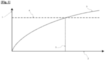
- FIG. 1 represents a graph showing the evolution of the bearing temperature on the turbine side as a function of time, according to the invention.
- FIG. 1 shows a graph representing the temperature 1 of the turbine bearing of a turbocharger of a vehicle internal combustion engine, the engine comprising an automatic stopping and restarting management system for this engine, as a function of the time from the stopping of the engine 2. It can be seen that the curve 3 obtained presents an evolution of the temperature of the turbine bearing which is progressive and reaches in a limited time 5 a critical temperature 4 from which coking of the oil at said bearing of said turbine of the turbocharger can occur. Generally, the time limit 5 is around 30 seconds.
- a two-dimensional map with the engine oil temperature on a first axis and the turbine bearing temperature on a second axis makes it possible to define a maximum engine shutdown duration, designated D max , below which we do not reach the critical temperature 4 of the turbine bearing.
- the thermal regulation method according to the invention authorizes or prohibits stopping or restarting the motor.
- D max is less than or equal to a previously defined time value, designated D 1 .
- D 1 designates a time value for which there is a high risk of reaching critical temperature 4 too quickly. It is then uninteresting, from an energy point of view, to turn the engine off and then on again a few seconds later.
- D max is between two predefined values, respectively lower and upper, designated D 2 and D 3 .
- the value of D max is stored in the memory of the vehicle's electronic control unit.
- the motor stop and start management function restarts the motor when the time from which the motor was stopped reaches the recorded D max value.
- the temperature of the turbine bearing does not reach the critical temperature 4 at which coking of the oil occurs.
- the two-dimensional mapping includes the temperature of the exhaust gases, filtered or not, on the second axis.
- the motor stopping and restarting management function therefore determines the authorization or prohibition of motor stopping depending on whether or not the bearing temperature exceeds the value of critical temperature 4.
Landscapes
- Engineering & Computer Science (AREA)
- Chemical & Material Sciences (AREA)
- Combustion & Propulsion (AREA)
- Mechanical Engineering (AREA)
- General Engineering & Computer Science (AREA)
- Supercharger (AREA)
- Output Control And Ontrol Of Special Type Engine (AREA)
- Hybrid Electric Vehicles (AREA)
Description
- L'invention concerne, de façon générale, le refroidissement du turbocompresseur d'un moteur, en particulier un moteur de véhicule automobile, à l'aide d'un circuit d'huile.
- L'invention porte plus précisément sur la détermination de la durée maximale de l'arrêt du moteur d'un véhicule, notamment d'un véhicule automobile, l'arrêt du moteur entraînant l'arrêt de la circulation d'huile et de l'évacuation de la chaleur.
- De manière connue, un turbocompresseur est constitué d'une turbine et d'un compresseur reliés par un axe reposant sur deux paliers, l'un des paliers étant situé au niveau de la turbine tandis que l'autre palier est situé au niveau du compresseur. Les deux paliers permettent la rotation guidée de l'axe sans frottements.
- Le turbocompresseur récupère les gaz d'échappement qui sortent du moteur et permet à la turbine reliée au compresseur d'air et placée à la sortie du collecteur d'échappement, d'être entraînée par les gaz d'échappement et d'effectuer une rotation. La rotation de la turbine entraine le compresseur, ce qui compresse l'air d'admission. Ce mouvement permet d'envoyer de l'air sous pression dans le circuit d'admission pour augmenter le remplissage du moteur, et obtenir une puissance supérieure qui, sans turbocompresseur, aurait nécessité une cylindrée supérieure.
- Cependant, la turbine et le carter de la turbine chauffent fortement le palier ainsi que le côté de l'axe se trouvant du côté de la turbine. L'axe reliant la turbine au compresseur et les deux paliers sont alors lubrifiés et refroidis par une circulation d'huile afin d'éviter tout surchauffage.
- Mais, lorsque le moteur s'arrête, la circulation d'huile s'arrête également, l'évacuation de chaleur ne peut alors plus continuer.
- En revanche, lorsque la turbine et le carter de la turbine sont très chauds, ils vont continuer à dissiper de la chaleur et la température de l'huile présente entre l'axe et le palier de la turbine va augmenter fortement. Il se crée alors un dépôt de matière abrasive qui s'accroît à chaque arrêt du moment, ce procédé étant appelé cokéfaction.
- Or, le turbocompresseur peut être endommagé par ce dépôt de matière abrasive, ce qui peut entraîner des désagréments pouvant nuire au moteur comme une consommation excessive d'huile, un grippage du mouvement de rotation de la turbine ou la détérioration d'un des éléments du turbocompresseur.
- En outre, sur les motorisations hybrides le moteur peut s'arrêter chaque fois que le véhicule s'arrête, le nombre d'arrêts du moteur est donc important.
- De manière connue, il existe un dispositif de contrôle du refroidissement du moteur capable d'assurer convenablement le contrôle de la température du liquide de refroidissement d'un moteur sans perdre de carburant. Il s'agit d'une unité de contrôle électronique commandant l'alimentation électrique pour entraîner une pompe à eau motorisée afin de réguler le débit du liquide de refroidissement à évacuer de la pompe à eau et contrôler l'alimentation électrique pour alimenter un réchauffeur régulant l'ouverture d'un élément de soupape d'un thermostat électronique et ainsi contrôler la température du liquide de refroidissement.
- L'unité de contrôle électronique corrige la puissance électrique alimentant le réchauffeur en fonction de la différence entre une valeur détectée de la température du liquide de refroidissement et une consigne de valeur de température. La correction appliquée est donc en fonction de l'écart de température du liquide de refroidissement avant et après le passage dans le moteur, elle est comparée à une valeur de référence.
- On connaît par le document
CN107893697 un procédé de commande électronique de l'ouverture d'un thermostat contrôlant la température du moteur. Dans ce cas, un degré précis d'ouverture du thermostat est contrôlé, afin d'aboutir à une température de fonctionnement ciblée. Plusieurs éléments sont alors pris en compte comme la température du liquide de refroidissement, la climatisation, la vitesse du véhicule. - Cependant une telle solution présente des inconvénients car elle nécessite l'utilisation d'un refroidissement additionnel à l'aide d'une pompe à eau électrique ou d'une pompe à huile électrique. Elle ne tient pas compte du fait que le roulement de l'axe joignant le compresseur à la turbine d'un turbocompresseur est refroidi avec de l'huile. A chaque fois que le moteur s'arrête, le débit d'huile s'arrête également, et l'huile restante est exposée à la cokéfaction. De plus, lorsque la fonction d'arrêt et de démarrage d'un véhicule est activée, le risque de cokéfaction est encore plus élevé.
- On connaît du document
WO2016007203A1 un procédé de régulation thermique d'un turbocompresseur pour un moteur comprenant un système de gestion d'arrêt et de redémarrage automatique de ce moteur. - L'invention vise donc à résoudre ces inconvénients en proposant un procédé de régulation thermique d'un turbocompresseur d'un moteur permettant de prédéfinir un arrêt planifié déclenché par la fonction d'arrêt et de démarrage dans certaines conditions de température.
- Pour parvenir à ce résultat, la présente invention concerne un de régulation thermique d'un turbocompresseur, le turbocompresseur étant destiné à suralimenter un moteur à combustion interne de véhicule en air comprimé, le moteur comprenant un système de gestion d'arrêt et de redémarrage automatique de ce moteur, le turbocompresseur comprenant une turbine traversée par des gaz d'échappement et comprenant un premier palier lubrifié par une circulation d'huile, caractérisé en ce que ledit procédé comprend :
- la détermination d'un seuil de température du premier palier à partir duquel se produit la cokéfaction de l'huile,
- la détermination d'une durée maximale de l'arrêt du moteur lors d'une demande d'arrêt automatique du moteur en dessous de laquelle on n'atteint pas le seuil de température à partir duquel se produit la cokéfaction de l'huile,
- si ladite durée maximale de l'arrêt du moteur est comprise dans une échelle de temps comprenant une valeur inférieure et une valeur supérieure, le procédé comprend l'arrêt automatique du moteur est autorisé, ladite valeur inférieure et ladite valeur supérieure étant prédéfinies,
- suite à l'arrêt automatique du moteur, le redémarrage automatique du moteur si la durée maximale est dépassée.
- Selon un mode de réalisation, ladite durée maximale de l'arrêt déterminé du moteur comprend une durée limite, prédéfinie, en-dessous de laquelle l'arrêt automatique du moteur est interdit.
- Selon un mode de réalisation, au-delà de ladite valeur supérieure, le procédé comprend l'arrêt et le redémarrage automatique du moteur sont toujours autorisés.
- Selon un mode de réalisation, ladite durée maximale de l'arrêt du moteur est mémorisée par une unité électronique de commande du moteur et en ce que le procédé comprend le redémarrage automatique du moteur lorsque le temps d'arrêt du moteur atteint la valeur de mémorisée.
- Selon un mode de réalisation, l'application d'une cartographie à deux dimensions prédéfinie détermine la durée maximale de l'arrêt du moteur, en fonction de la température de l'huile dans le moteur et d'une température représentative de la température du palier de la turbine.
- Selon un mode de réalisation, la cartographie à deux dimensions comprend la température de l'huile dans le moteur sur un premier axe et la température du premier palier de la turbine sur un deuxième axe.
- Selon un mode de réalisation, la cartographie à deux dimensions comprend la température de l'huile dans le moteur sur un premier axe et la température de gaz d'échappement sur un deuxième axe.
- Selon un mode de réalisation, la température des gaz d'échappement est mesurée après filtration.
- La présente invention vise aussi véhicule automobile comprenant un moteur à combustion interne comportant un turbocompresseur, ainsi qu'un calculateur de contrôle moteur configuré pour mettre en oeuvre le procédé de régulation thermique dudit turbocompresseur tel que brièvement décrit ci-dessus.
- D'autres caractéristiques et avantages de l'invention apparaîtront à la lecture de la description détaillée des modes de réalisation de l'invention, donnés à titre d'exemple uniquement, et en référence au dessin qui montre :
[Fig. 1 ] représente un graphique montrant l'évolution de la température de palier du côté de la turbine en fonction du temps, selon l'invention. - La
figure 1 montre un graphique représentant la température 1 du palier de la turbine d'un turbocompresseur d'un moteur à combustion interne de véhicule, le moteur comprenant un système de gestion d'arrêt et de redémarrage automatique de ce moteur , en fonction du temps à partir de l'arrêt du moteur 2. On constate que la courbe 3 obtenue présente une évolution de la température du palier de la turbine qui est progressive et atteint en un temps limite 5 une température critique 4 à partir de laquelle la cokéfaction de l'huile au niveau dudit palier de ladite turbine du turbocompresseur peut se produire. Généralement, le temps limite 5 est de l'ordre de 30 secondes. - Une cartographie à deux dimensions avec la température de l'huile du moteur sur un premier axe et la température du palier de la turbine sur un deuxième axe permet de définir une durée maximale de l'arrêt du moteur, désignée Dmax, en dessous de laquelle on n'atteint pas la température critique 4 du palier de la turbine.
- Lors d'une demande d'une demande d'arrêt automatique du moteur, la valeur de Dmax, est calculée.
- Selon la valeur de Dmax, le procédé de régulation thermique selon l'invention autorise ou interdit l'arrêt ou le redémarrage du moteur.
- Plus précisément, si Dmax est inférieur ou égal à une valeur du temps préalablement définie, désignée D1, les arrêts automatiques du moteur sont interdits sauf si l'utilisateur décide de couper lui-même le moteur de son véhicule.
- En effet, D1 désigne une valeur du temps pour laquelle il existe un risque élevé d'atteindre la température critique 4 trop rapidement. Il est alors inintéressant, d'un point de vue énergétique, de couper puis de rallumer le moteur quelques secondes plus tard.
- Si Dmax est compris entre deux valeurs, respectivement inférieure et supérieure, prédéfinies, désignées D2 et D3, les arrêts automatiques du moteur sont autorisés.
- Lors de l'arrêt du moteur, la valeur de Dmax est enregistrée dans la mémoire de l'unité de contrôle électronique du véhicule.
- Après l'arrêt automatique du moteur, la fonction de gestion de l'arrêt et du redémarrage du moteur redémarre le moteur lorsque le temps à partir duquel le moteur a été arrêté atteint la valeur de Dmax enregistrée. Ainsi, la température du palier de la turbine n'atteint pas la température critique 4 à laquelle se produit la cokéfaction de l'huile.
- Enfin, si la valeur de Dmax est supérieure à la valeur supérieure D3, l'arrêt du moteur et son redémarrage sont toujours autorisés.
- Selon une variante de l'invention, la cartographie à deux dimensions comprend la température des gaz d'échappement, filtrée ou non, sur le deuxième axe.
- La fonction de gestion de l'arrêt et du redémarrage du moteur détermine donc l'autorisation ou l'interdiction de l'arrêt du moteur selon que la température du palier dépasse ou non la valeur de la température critique 4.
Claims (9)
- Procédé de régulation thermique d'un turbocompresseur, le turbocompresseur étant destiné à suralimenter un moteur à combustion interne de véhicule en air comprimé, le moteur comprenant un système de gestion d'arrêt et de redémarrage automatique de ce moteur, le turbocompresseur comprenant une turbine traversée par des gaz d'échappement et comprenant un palier lubrifié par une circulation d'huile, ledit procédé comprend :- la détermination d'un seuil de température du palier à partir duquel se produit la cokéfaction de l'huile,- la détermination d'une durée maximale de l'arrêt du moteur lors d'une demande d'arrêt automatique du moteur en dessous de laquelle on n'atteint pas le seuil de température à partir duquel se produit la cokéfaction de l'huile, et est caractérisé en ce qu'il comprend- si ladite durée maximale de l'arrêt du moteur est comprise dans une échelle de temps comprenant une valeur inférieure et une valeur supérieure, l'arrêt automatique du moteur est autorisé, ladite valeur inférieure et ladite valeur supérieure étant prédéfinies,- suite à l'arrêt automatique du moteur, le redémarrage automatique du moteur si la durée maximale est dépassée.
- Procédé de régulation thermique d'un turbocompresseur selon la revendication 1, caractérisé en ce que ladite durée maximale de l'arrêt du moteur déterminée comprend une durée limite, prédéfinie, en-dessous de laquelle l'arrêt automatique du moteur est interdit.
- Procédé de régulation thermique d'un turbocompresseur selon la revendication 1 ou la revendication 2, caractérisé en ce que, au-delà de ladite valeur supérieure, l'arrêt et le redémarrage automatique du moteur sont toujours autorisés.
- Procédé de régulation thermique d'un turbocompresseur selon l'une des revendications précédentes, caractérisé en ce que ladite durée maximale de l'arrêt du moteur est mémorisée par une unité électronique de commande du moteur et en ce que le procédé comprend le redémarrage automatique du moteur lorsque le temps d'arrêt du moteur atteint la valeur de mémorisée.
- Procédé de régulation thermique d'un turbocompresseur selon l'une des revendications précédentes, caractérisé en ce que l'application d'une cartographie à deux dimensions prédéfinie détermine la durée maximale de l'arrêt du moteur, en fonction de la température de l'huile dans le moteur et d'une température représentative de la température du premier palier de la turbine.
- Procédé de régulation thermique d'un turbocompresseur selon la revendication précédente, caractérisé en ce que la cartographie à deux dimensions comprend la température de l'huile dans le moteur sur un premier axe et la température du palier de la turbine sur un deuxième axe.
- Procédé de régulation thermique d'un turbocompresseur selon la revendication 5, caractérisé en ce que la cartographie à deux dimensions comprend la température de l'huile dans le moteur sur un premier axe et la température de gaz d'échappement sur un deuxième axe.
- Procédé de régulation thermique d'un turbocompresseur selon la revendication précédente, dans lequel la température des gaz d'échappement est mesurée après filtration.
- Véhicule automobile comprenant un moteur à combustion interne comportant un turbocompresseur, ainsi qu'un calculateur de contrôle moteur configuré pour mettre en oeuvre le procédé de régulation thermique d'un turbocompresseur selon l'une des revendications précédentes.
Applications Claiming Priority (2)
| Application Number | Priority Date | Filing Date | Title |
|---|---|---|---|
| FR1873521A FR3090741B1 (fr) | 2018-12-20 | 2018-12-20 | Dispositif de refroidissement d’un turbocompresseur d’un moteur hybride |
| PCT/FR2019/052752 WO2020128174A1 (fr) | 2018-12-20 | 2019-11-19 | Dispositif de refroidissement d'un turbocompresseur d'un moteur hybride |
Publications (2)
| Publication Number | Publication Date |
|---|---|
| EP3899224A1 EP3899224A1 (fr) | 2021-10-27 |
| EP3899224B1 true EP3899224B1 (fr) | 2024-04-17 |
Family
ID=66776469
Family Applications (1)
| Application Number | Title | Priority Date | Filing Date |
|---|---|---|---|
| EP19823800.8A Active EP3899224B1 (fr) | 2018-12-20 | 2019-11-19 | Dispositif de refroidissement d'un turbocompresseur d'un moteur hybride |
Country Status (3)
| Country | Link |
|---|---|
| EP (1) | EP3899224B1 (fr) |
| FR (1) | FR3090741B1 (fr) |
| WO (1) | WO2020128174A1 (fr) |
Family Cites Families (4)
| Publication number | Priority date | Publication date | Assignee | Title |
|---|---|---|---|---|
| JPS59221441A (ja) * | 1983-05-30 | 1984-12-13 | Toyota Motor Corp | エンジン自動停止始動装置 |
| DE102010043920B4 (de) * | 2010-11-15 | 2014-09-11 | Ford Global Technologies, Llc | Verfahren zum Vermeiden von Turboladerschäden |
| US9447764B2 (en) * | 2014-07-10 | 2016-09-20 | Cummins Inc. | Internal combustion engine start-stop controls |
| CN107893697B (zh) | 2017-11-24 | 2020-04-07 | 奇瑞汽车股份有限公司 | 一种电子节温器开度控制方法 |
-
2018
- 2018-12-20 FR FR1873521A patent/FR3090741B1/fr active Active
-
2019
- 2019-11-19 EP EP19823800.8A patent/EP3899224B1/fr active Active
- 2019-11-19 WO PCT/FR2019/052752 patent/WO2020128174A1/fr not_active Ceased
Also Published As
| Publication number | Publication date |
|---|---|
| EP3899224A1 (fr) | 2021-10-27 |
| FR3090741B1 (fr) | 2020-12-18 |
| WO2020128174A1 (fr) | 2020-06-25 |
| FR3090741A1 (fr) | 2020-06-26 |
Similar Documents
| Publication | Publication Date | Title |
|---|---|---|
| EP2417338B1 (fr) | Dispositif de refroidissement pour véhicule automobile | |
| FR2916586A1 (fr) | Appareil de commande et moteur-generateur integre | |
| FR2829531A1 (fr) | Appareil de commande du moment de mise en marche et appareil de commande du moment d'arret d'un moteur a combustion interne, procedes de commande de ceux-ci et supports d'enregistrement | |
| EP1264086B1 (fr) | Procede et dispositif de refroidissement d'un moteur de vehicule automobile | |
| FR2982316A1 (fr) | Procede de regeneration d'un filtre a particules pour vehicule automobile hybrideprocede de regeneration d'un filtre a particules pour vehicule automobile hybride | |
| FR2958581A1 (fr) | Dispositif de refroidissement pour vehicule automobile | |
| WO2008059152A1 (fr) | Procede de commande d'un dispositif d'arret et de redemarrage automatique d'un moteur thermique | |
| EP3899224B1 (fr) | Dispositif de refroidissement d'un turbocompresseur d'un moteur hybride | |
| EP2806143A1 (fr) | Procédé d'arrêt d'un moteur thermique de véhicule automobile | |
| FR2519694A1 (fr) | Circuit hydraulique economique pour le refroidissement d'un moteur a combustion interne de vehicule automobile | |
| FR3012520A1 (fr) | Ligne d'echappement de moteur a combustion interne | |
| EP3390797B1 (fr) | Procédé de pilotage d'un moteur à combustion interne suralimenté et moteur suralimenté associé | |
| FR2787141A1 (fr) | Moteur a combustion interne suralimente | |
| WO2007085752A2 (fr) | Dispositif permettant d'accelerer la montee en temperature d'huile de lubrification d'un moteur a combustion interne a turbocompresseur a gaz d'echappement | |
| WO2015140432A1 (fr) | Procédé de gestion du fonctionnement d'un demarreur d'un moteur thermique afin d'éviter une éventuelle surchauffe pendant le démarrage | |
| FR2960592A1 (fr) | Procede de demarrage d'un moteur d'aeronef | |
| FR3013395A1 (fr) | Procede et systeme d'alimentation en gazole d'un vehicule automobile. | |
| EP3894684B1 (fr) | Procede de chauffage du liquide de refroidissement d'un moteur a combustion interne apres un demarrage a froid | |
| FR3031139A1 (fr) | Procede de regulation de la temperature d'huile de lubrification d'un moteur | |
| FR2857913A1 (fr) | Procede et dispositif de commande d'un moteur de vehicule | |
| FR3002976A1 (fr) | Procede de mise en œuvre d'un circuit de refroidissement | |
| EP2128414A1 (fr) | Procédé de contrôle moteur | |
| EP3450718A1 (fr) | Systeme d'alimentation en gaz pour un moteur à combustion interne | |
| FR3067061B1 (fr) | Systeme d'alimentation d'un moteur a combustion interne | |
| FR3059722A1 (fr) | Procede et systeme de protection d'une roue d'un compresseur d'un turbocompresseur |
Legal Events
| Date | Code | Title | Description |
|---|---|---|---|
| STAA | Information on the status of an ep patent application or granted ep patent |
Free format text: STATUS: UNKNOWN |
|
| STAA | Information on the status of an ep patent application or granted ep patent |
Free format text: STATUS: THE INTERNATIONAL PUBLICATION HAS BEEN MADE |
|
| PUAI | Public reference made under article 153(3) epc to a published international application that has entered the european phase |
Free format text: ORIGINAL CODE: 0009012 |
|
| STAA | Information on the status of an ep patent application or granted ep patent |
Free format text: STATUS: REQUEST FOR EXAMINATION WAS MADE |
|
| 17P | Request for examination filed |
Effective date: 20210517 |
|
| AK | Designated contracting states |
Kind code of ref document: A1 Designated state(s): AL AT BE BG CH CY CZ DE DK EE ES FI FR GB GR HR HU IE IS IT LI LT LU LV MC MK MT NL NO PL PT RO RS SE SI SK SM TR |
|
| DAV | Request for validation of the european patent (deleted) | ||
| DAX | Request for extension of the european patent (deleted) | ||
| GRAP | Despatch of communication of intention to grant a patent |
Free format text: ORIGINAL CODE: EPIDOSNIGR1 |
|
| STAA | Information on the status of an ep patent application or granted ep patent |
Free format text: STATUS: GRANT OF PATENT IS INTENDED |
|
| RAP3 | Party data changed (applicant data changed or rights of an application transferred) |
Owner name: STELLANTIS AUTO SAS |
|
| INTG | Intention to grant announced |
Effective date: 20231208 |
|
| GRAS | Grant fee paid |
Free format text: ORIGINAL CODE: EPIDOSNIGR3 |
|
| GRAA | (expected) grant |
Free format text: ORIGINAL CODE: 0009210 |
|
| STAA | Information on the status of an ep patent application or granted ep patent |
Free format text: STATUS: THE PATENT HAS BEEN GRANTED |
|
| AK | Designated contracting states |
Kind code of ref document: B1 Designated state(s): AL AT BE BG CH CY CZ DE DK EE ES FI FR GB GR HR HU IE IS IT LI LT LU LV MC MK MT NL NO PL PT RO RS SE SI SK SM TR |
|
| REG | Reference to a national code |
Ref country code: GB Ref legal event code: FG4D Free format text: NOT ENGLISH |
|
| REG | Reference to a national code |
Ref country code: CH Ref legal event code: EP |
|
| REG | Reference to a national code |
Ref country code: DE Ref legal event code: R096 Ref document number: 602019050553 Country of ref document: DE |
|
| REG | Reference to a national code |
Ref country code: IE Ref legal event code: FG4D Free format text: LANGUAGE OF EP DOCUMENT: FRENCH |
|
| REG | Reference to a national code |
Ref country code: LT Ref legal event code: MG9D |
|
| REG | Reference to a national code |
Ref country code: NL Ref legal event code: MP Effective date: 20240417 |
|
| REG | Reference to a national code |
Ref country code: AT Ref legal event code: MK05 Ref document number: 1677447 Country of ref document: AT Kind code of ref document: T Effective date: 20240417 |
|
| PG25 | Lapsed in a contracting state [announced via postgrant information from national office to epo] |
Ref country code: NL Free format text: LAPSE BECAUSE OF FAILURE TO SUBMIT A TRANSLATION OF THE DESCRIPTION OR TO PAY THE FEE WITHIN THE PRESCRIBED TIME-LIMIT Effective date: 20240417 |
|
| PG25 | Lapsed in a contracting state [announced via postgrant information from national office to epo] |
Ref country code: NL Free format text: LAPSE BECAUSE OF FAILURE TO SUBMIT A TRANSLATION OF THE DESCRIPTION OR TO PAY THE FEE WITHIN THE PRESCRIBED TIME-LIMIT Effective date: 20240417 |
|
| PG25 | Lapsed in a contracting state [announced via postgrant information from national office to epo] |
Ref country code: IS Free format text: LAPSE BECAUSE OF FAILURE TO SUBMIT A TRANSLATION OF THE DESCRIPTION OR TO PAY THE FEE WITHIN THE PRESCRIBED TIME-LIMIT Effective date: 20240817 |
|
| PG25 | Lapsed in a contracting state [announced via postgrant information from national office to epo] |
Ref country code: BG Free format text: LAPSE BECAUSE OF FAILURE TO SUBMIT A TRANSLATION OF THE DESCRIPTION OR TO PAY THE FEE WITHIN THE PRESCRIBED TIME-LIMIT Effective date: 20240417 |
|
| PG25 | Lapsed in a contracting state [announced via postgrant information from national office to epo] |
Ref country code: HR Free format text: LAPSE BECAUSE OF FAILURE TO SUBMIT A TRANSLATION OF THE DESCRIPTION OR TO PAY THE FEE WITHIN THE PRESCRIBED TIME-LIMIT Effective date: 20240417 Ref country code: FI Free format text: LAPSE BECAUSE OF FAILURE TO SUBMIT A TRANSLATION OF THE DESCRIPTION OR TO PAY THE FEE WITHIN THE PRESCRIBED TIME-LIMIT Effective date: 20240417 |
|
| PG25 | Lapsed in a contracting state [announced via postgrant information from national office to epo] |
Ref country code: GR Free format text: LAPSE BECAUSE OF FAILURE TO SUBMIT A TRANSLATION OF THE DESCRIPTION OR TO PAY THE FEE WITHIN THE PRESCRIBED TIME-LIMIT Effective date: 20240718 |
|
| PG25 | Lapsed in a contracting state [announced via postgrant information from national office to epo] |
Ref country code: PT Free format text: LAPSE BECAUSE OF FAILURE TO SUBMIT A TRANSLATION OF THE DESCRIPTION OR TO PAY THE FEE WITHIN THE PRESCRIBED TIME-LIMIT Effective date: 20240819 |
|
| PG25 | Lapsed in a contracting state [announced via postgrant information from national office to epo] |
Ref country code: ES Free format text: LAPSE BECAUSE OF FAILURE TO SUBMIT A TRANSLATION OF THE DESCRIPTION OR TO PAY THE FEE WITHIN THE PRESCRIBED TIME-LIMIT Effective date: 20240417 |
|
| REG | Reference to a national code |
Ref country code: DE Ref legal event code: R084 Ref document number: 602019050553 Country of ref document: DE |
|
| PG25 | Lapsed in a contracting state [announced via postgrant information from national office to epo] |
Ref country code: AT Free format text: LAPSE BECAUSE OF FAILURE TO SUBMIT A TRANSLATION OF THE DESCRIPTION OR TO PAY THE FEE WITHIN THE PRESCRIBED TIME-LIMIT Effective date: 20240417 |
|
| PG25 | Lapsed in a contracting state [announced via postgrant information from national office to epo] |
Ref country code: PL Free format text: LAPSE BECAUSE OF FAILURE TO SUBMIT A TRANSLATION OF THE DESCRIPTION OR TO PAY THE FEE WITHIN THE PRESCRIBED TIME-LIMIT Effective date: 20240417 |
|
| PG25 | Lapsed in a contracting state [announced via postgrant information from national office to epo] |
Ref country code: LV Free format text: LAPSE BECAUSE OF FAILURE TO SUBMIT A TRANSLATION OF THE DESCRIPTION OR TO PAY THE FEE WITHIN THE PRESCRIBED TIME-LIMIT Effective date: 20240417 |
|
| PG25 | Lapsed in a contracting state [announced via postgrant information from national office to epo] |
Ref country code: PT Free format text: LAPSE BECAUSE OF FAILURE TO SUBMIT A TRANSLATION OF THE DESCRIPTION OR TO PAY THE FEE WITHIN THE PRESCRIBED TIME-LIMIT Effective date: 20240819 Ref country code: PL Free format text: LAPSE BECAUSE OF FAILURE TO SUBMIT A TRANSLATION OF THE DESCRIPTION OR TO PAY THE FEE WITHIN THE PRESCRIBED TIME-LIMIT Effective date: 20240417 Ref country code: NO Free format text: LAPSE BECAUSE OF FAILURE TO SUBMIT A TRANSLATION OF THE DESCRIPTION OR TO PAY THE FEE WITHIN THE PRESCRIBED TIME-LIMIT Effective date: 20240717 Ref country code: LV Free format text: LAPSE BECAUSE OF FAILURE TO SUBMIT A TRANSLATION OF THE DESCRIPTION OR TO PAY THE FEE WITHIN THE PRESCRIBED TIME-LIMIT Effective date: 20240417 Ref country code: IS Free format text: LAPSE BECAUSE OF FAILURE TO SUBMIT A TRANSLATION OF THE DESCRIPTION OR TO PAY THE FEE WITHIN THE PRESCRIBED TIME-LIMIT Effective date: 20240817 Ref country code: HR Free format text: LAPSE BECAUSE OF FAILURE TO SUBMIT A TRANSLATION OF THE DESCRIPTION OR TO PAY THE FEE WITHIN THE PRESCRIBED TIME-LIMIT Effective date: 20240417 Ref country code: GR Free format text: LAPSE BECAUSE OF FAILURE TO SUBMIT A TRANSLATION OF THE DESCRIPTION OR TO PAY THE FEE WITHIN THE PRESCRIBED TIME-LIMIT Effective date: 20240718 Ref country code: FI Free format text: LAPSE BECAUSE OF FAILURE TO SUBMIT A TRANSLATION OF THE DESCRIPTION OR TO PAY THE FEE WITHIN THE PRESCRIBED TIME-LIMIT Effective date: 20240417 Ref country code: ES Free format text: LAPSE BECAUSE OF FAILURE TO SUBMIT A TRANSLATION OF THE DESCRIPTION OR TO PAY THE FEE WITHIN THE PRESCRIBED TIME-LIMIT Effective date: 20240417 Ref country code: BG Free format text: LAPSE BECAUSE OF FAILURE TO SUBMIT A TRANSLATION OF THE DESCRIPTION OR TO PAY THE FEE WITHIN THE PRESCRIBED TIME-LIMIT Effective date: 20240417 Ref country code: AT Free format text: LAPSE BECAUSE OF FAILURE TO SUBMIT A TRANSLATION OF THE DESCRIPTION OR TO PAY THE FEE WITHIN THE PRESCRIBED TIME-LIMIT Effective date: 20240417 Ref country code: RS Free format text: LAPSE BECAUSE OF FAILURE TO SUBMIT A TRANSLATION OF THE DESCRIPTION OR TO PAY THE FEE WITHIN THE PRESCRIBED TIME-LIMIT Effective date: 20240717 |
|
| PG25 | Lapsed in a contracting state [announced via postgrant information from national office to epo] |
Ref country code: DK Free format text: LAPSE BECAUSE OF FAILURE TO SUBMIT A TRANSLATION OF THE DESCRIPTION OR TO PAY THE FEE WITHIN THE PRESCRIBED TIME-LIMIT Effective date: 20240417 |
|
| REG | Reference to a national code |
Ref country code: DE Ref legal event code: R097 Ref document number: 602019050553 Country of ref document: DE |
|
| PG25 | Lapsed in a contracting state [announced via postgrant information from national office to epo] |
Ref country code: EE Free format text: LAPSE BECAUSE OF FAILURE TO SUBMIT A TRANSLATION OF THE DESCRIPTION OR TO PAY THE FEE WITHIN THE PRESCRIBED TIME-LIMIT Effective date: 20240417 |
|
| PG25 | Lapsed in a contracting state [announced via postgrant information from national office to epo] |
Ref country code: CZ Free format text: LAPSE BECAUSE OF FAILURE TO SUBMIT A TRANSLATION OF THE DESCRIPTION OR TO PAY THE FEE WITHIN THE PRESCRIBED TIME-LIMIT Effective date: 20240417 |
|
| PG25 | Lapsed in a contracting state [announced via postgrant information from national office to epo] |
Ref country code: SK Free format text: LAPSE BECAUSE OF FAILURE TO SUBMIT A TRANSLATION OF THE DESCRIPTION OR TO PAY THE FEE WITHIN THE PRESCRIBED TIME-LIMIT Effective date: 20240417 Ref country code: RO Free format text: LAPSE BECAUSE OF FAILURE TO SUBMIT A TRANSLATION OF THE DESCRIPTION OR TO PAY THE FEE WITHIN THE PRESCRIBED TIME-LIMIT Effective date: 20240417 |
|
| PG25 | Lapsed in a contracting state [announced via postgrant information from national office to epo] |
Ref country code: SM Free format text: LAPSE BECAUSE OF FAILURE TO SUBMIT A TRANSLATION OF THE DESCRIPTION OR TO PAY THE FEE WITHIN THE PRESCRIBED TIME-LIMIT Effective date: 20240417 |
|
| PG25 | Lapsed in a contracting state [announced via postgrant information from national office to epo] |
Ref country code: SM Free format text: LAPSE BECAUSE OF FAILURE TO SUBMIT A TRANSLATION OF THE DESCRIPTION OR TO PAY THE FEE WITHIN THE PRESCRIBED TIME-LIMIT Effective date: 20240417 Ref country code: SK Free format text: LAPSE BECAUSE OF FAILURE TO SUBMIT A TRANSLATION OF THE DESCRIPTION OR TO PAY THE FEE WITHIN THE PRESCRIBED TIME-LIMIT Effective date: 20240417 Ref country code: RO Free format text: LAPSE BECAUSE OF FAILURE TO SUBMIT A TRANSLATION OF THE DESCRIPTION OR TO PAY THE FEE WITHIN THE PRESCRIBED TIME-LIMIT Effective date: 20240417 Ref country code: EE Free format text: LAPSE BECAUSE OF FAILURE TO SUBMIT A TRANSLATION OF THE DESCRIPTION OR TO PAY THE FEE WITHIN THE PRESCRIBED TIME-LIMIT Effective date: 20240417 Ref country code: DK Free format text: LAPSE BECAUSE OF FAILURE TO SUBMIT A TRANSLATION OF THE DESCRIPTION OR TO PAY THE FEE WITHIN THE PRESCRIBED TIME-LIMIT Effective date: 20240417 Ref country code: CZ Free format text: LAPSE BECAUSE OF FAILURE TO SUBMIT A TRANSLATION OF THE DESCRIPTION OR TO PAY THE FEE WITHIN THE PRESCRIBED TIME-LIMIT Effective date: 20240417 |
|
| PG25 | Lapsed in a contracting state [announced via postgrant information from national office to epo] |
Ref country code: IT Free format text: LAPSE BECAUSE OF FAILURE TO SUBMIT A TRANSLATION OF THE DESCRIPTION OR TO PAY THE FEE WITHIN THE PRESCRIBED TIME-LIMIT Effective date: 20240417 |
|
| PLBE | No opposition filed within time limit |
Free format text: ORIGINAL CODE: 0009261 |
|
| STAA | Information on the status of an ep patent application or granted ep patent |
Free format text: STATUS: NO OPPOSITION FILED WITHIN TIME LIMIT |
|
| 26N | No opposition filed |
Effective date: 20250120 |
|
| PG25 | Lapsed in a contracting state [announced via postgrant information from national office to epo] |
Ref country code: SI Free format text: LAPSE BECAUSE OF FAILURE TO SUBMIT A TRANSLATION OF THE DESCRIPTION OR TO PAY THE FEE WITHIN THE PRESCRIBED TIME-LIMIT Effective date: 20240417 |
|
| REG | Reference to a national code |
Ref country code: CH Ref legal event code: PL |
|
| PG25 | Lapsed in a contracting state [announced via postgrant information from national office to epo] |
Ref country code: MC Free format text: LAPSE BECAUSE OF FAILURE TO SUBMIT A TRANSLATION OF THE DESCRIPTION OR TO PAY THE FEE WITHIN THE PRESCRIBED TIME-LIMIT Effective date: 20240417 |
|
| PG25 | Lapsed in a contracting state [announced via postgrant information from national office to epo] |
Ref country code: LU Free format text: LAPSE BECAUSE OF NON-PAYMENT OF DUE FEES Effective date: 20241119 |
|
| REG | Reference to a national code |
Ref country code: CH Ref legal event code: PL |
|
| GBPC | Gb: european patent ceased through non-payment of renewal fee |
Effective date: 20241119 |
|
| PG25 | Lapsed in a contracting state [announced via postgrant information from national office to epo] |
Ref country code: CH Free format text: LAPSE BECAUSE OF NON-PAYMENT OF DUE FEES Effective date: 20241130 |
|
| REG | Reference to a national code |
Ref country code: BE Ref legal event code: MM Effective date: 20241130 |
|
| PG25 | Lapsed in a contracting state [announced via postgrant information from national office to epo] |
Ref country code: SE Free format text: LAPSE BECAUSE OF FAILURE TO SUBMIT A TRANSLATION OF THE DESCRIPTION OR TO PAY THE FEE WITHIN THE PRESCRIBED TIME-LIMIT Effective date: 20240417 |
|
| PG25 | Lapsed in a contracting state [announced via postgrant information from national office to epo] |
Ref country code: GB Free format text: LAPSE BECAUSE OF NON-PAYMENT OF DUE FEES Effective date: 20241119 Ref country code: BE Free format text: LAPSE BECAUSE OF NON-PAYMENT OF DUE FEES Effective date: 20241130 |
|
| PG25 | Lapsed in a contracting state [announced via postgrant information from national office to epo] |
Ref country code: IE Free format text: LAPSE BECAUSE OF NON-PAYMENT OF DUE FEES Effective date: 20241119 |
|
| PGFP | Annual fee paid to national office [announced via postgrant information from national office to epo] |
Ref country code: DE Payment date: 20251022 Year of fee payment: 7 |
|
| PGFP | Annual fee paid to national office [announced via postgrant information from national office to epo] |
Ref country code: FR Payment date: 20251022 Year of fee payment: 7 |
|
| PGFP | Annual fee paid to national office [announced via postgrant information from national office to epo] |
Ref country code: TR Payment date: 20251028 Year of fee payment: 7 |
|
| PG25 | Lapsed in a contracting state [announced via postgrant information from national office to epo] |
Ref country code: HU Free format text: LAPSE BECAUSE OF FAILURE TO SUBMIT A TRANSLATION OF THE DESCRIPTION OR TO PAY THE FEE WITHIN THE PRESCRIBED TIME-LIMIT; INVALID AB INITIO Effective date: 20191119 |
|
| PG25 | Lapsed in a contracting state [announced via postgrant information from national office to epo] |
Ref country code: CY Free format text: LAPSE BECAUSE OF FAILURE TO SUBMIT A TRANSLATION OF THE DESCRIPTION OR TO PAY THE FEE WITHIN THE PRESCRIBED TIME-LIMIT; INVALID AB INITIO Effective date: 20191119 |