EP3899231B1 - Moteur à combustion interne avec post-traitement des gaz d'échappement et commande des émissions d'oxyde d'azote - Google Patents
Moteur à combustion interne avec post-traitement des gaz d'échappement et commande des émissions d'oxyde d'azote Download PDFInfo
- Publication number
- EP3899231B1 EP3899231B1 EP18829716.2A EP18829716A EP3899231B1 EP 3899231 B1 EP3899231 B1 EP 3899231B1 EP 18829716 A EP18829716 A EP 18829716A EP 3899231 B1 EP3899231 B1 EP 3899231B1
- Authority
- EP
- European Patent Office
- Prior art keywords
- internal combustion
- combustion engine
- engine
- loop control
- closed
- Prior art date
- Legal status (The legal status is an assumption and is not a legal conclusion. Google has not performed a legal analysis and makes no representation as to the accuracy of the status listed.)
- Active
Links
Images


Classifications
-
- F—MECHANICAL ENGINEERING; LIGHTING; HEATING; WEAPONS; BLASTING
- F02—COMBUSTION ENGINES; HOT-GAS OR COMBUSTION-PRODUCT ENGINE PLANTS
- F02D—CONTROLLING COMBUSTION ENGINES
- F02D41/00—Electrical control of supply of combustible mixture or its constituents
- F02D41/02—Circuit arrangements for generating control signals
- F02D41/14—Introducing closed-loop corrections
- F02D41/1438—Introducing closed-loop corrections using means for determining characteristics of the combustion gases; Sensors therefor
- F02D41/1444—Introducing closed-loop corrections using means for determining characteristics of the combustion gases; Sensors therefor characterised by the characteristics of the combustion gases
- F02D41/146—Introducing closed-loop corrections using means for determining characteristics of the combustion gases; Sensors therefor characterised by the characteristics of the combustion gases the characteristics being an NOx content or concentration
- F02D41/1461—Introducing closed-loop corrections using means for determining characteristics of the combustion gases; Sensors therefor characterised by the characteristics of the combustion gases the characteristics being an NOx content or concentration of the exhaust gases emitted by the engine
-
- F—MECHANICAL ENGINEERING; LIGHTING; HEATING; WEAPONS; BLASTING
- F02—COMBUSTION ENGINES; HOT-GAS OR COMBUSTION-PRODUCT ENGINE PLANTS
- F02D—CONTROLLING COMBUSTION ENGINES
- F02D29/00—Controlling engines, such controlling being peculiar to the devices driven thereby, the devices being other than parts or accessories essential to engine operation, e.g. controlling of engines by signals external thereto
- F02D29/06—Controlling engines, such controlling being peculiar to the devices driven thereby, the devices being other than parts or accessories essential to engine operation, e.g. controlling of engines by signals external thereto peculiar to engines driving electric generators
-
- F—MECHANICAL ENGINEERING; LIGHTING; HEATING; WEAPONS; BLASTING
- F02—COMBUSTION ENGINES; HOT-GAS OR COMBUSTION-PRODUCT ENGINE PLANTS
- F02D—CONTROLLING COMBUSTION ENGINES
- F02D41/00—Electrical control of supply of combustible mixture or its constituents
- F02D41/0002—Controlling intake air
- F02D41/0007—Controlling intake air for control of turbo-charged or super-charged engines
-
- F—MECHANICAL ENGINEERING; LIGHTING; HEATING; WEAPONS; BLASTING
- F02—COMBUSTION ENGINES; HOT-GAS OR COMBUSTION-PRODUCT ENGINE PLANTS
- F02D—CONTROLLING COMBUSTION ENGINES
- F02D41/00—Electrical control of supply of combustible mixture or its constituents
- F02D41/02—Circuit arrangements for generating control signals
- F02D41/14—Introducing closed-loop corrections
- F02D41/1438—Introducing closed-loop corrections using means for determining characteristics of the combustion gases; Sensors therefor
- F02D41/1444—Introducing closed-loop corrections using means for determining characteristics of the combustion gases; Sensors therefor characterised by the characteristics of the combustion gases
- F02D41/1446—Introducing closed-loop corrections using means for determining characteristics of the combustion gases; Sensors therefor characterised by the characteristics of the combustion gases the characteristics being exhaust temperatures
-
- F—MECHANICAL ENGINEERING; LIGHTING; HEATING; WEAPONS; BLASTING
- F02—COMBUSTION ENGINES; HOT-GAS OR COMBUSTION-PRODUCT ENGINE PLANTS
- F02D—CONTROLLING COMBUSTION ENGINES
- F02D41/00—Electrical control of supply of combustible mixture or its constituents
- F02D41/02—Circuit arrangements for generating control signals
- F02D41/14—Introducing closed-loop corrections
- F02D41/1438—Introducing closed-loop corrections using means for determining characteristics of the combustion gases; Sensors therefor
- F02D41/1444—Introducing closed-loop corrections using means for determining characteristics of the combustion gases; Sensors therefor characterised by the characteristics of the combustion gases
- F02D41/146—Introducing closed-loop corrections using means for determining characteristics of the combustion gases; Sensors therefor characterised by the characteristics of the combustion gases the characteristics being an NOx content or concentration
- F02D41/1463—Introducing closed-loop corrections using means for determining characteristics of the combustion gases; Sensors therefor characterised by the characteristics of the combustion gases the characteristics being an NOx content or concentration of the exhaust gases downstream of exhaust gas treatment apparatus
-
- F—MECHANICAL ENGINEERING; LIGHTING; HEATING; WEAPONS; BLASTING
- F02—COMBUSTION ENGINES; HOT-GAS OR COMBUSTION-PRODUCT ENGINE PLANTS
- F02D—CONTROLLING COMBUSTION ENGINES
- F02D41/00—Electrical control of supply of combustible mixture or its constituents
- F02D41/02—Circuit arrangements for generating control signals
- F02D41/14—Introducing closed-loop corrections
- F02D41/1438—Introducing closed-loop corrections using means for determining characteristics of the combustion gases; Sensors therefor
- F02D41/1473—Introducing closed-loop corrections using means for determining characteristics of the combustion gases; Sensors therefor characterised by the regulation method
- F02D41/1475—Regulating the air fuel ratio at a value other than stoichiometry
-
- F—MECHANICAL ENGINEERING; LIGHTING; HEATING; WEAPONS; BLASTING
- F02—COMBUSTION ENGINES; HOT-GAS OR COMBUSTION-PRODUCT ENGINE PLANTS
- F02P—IGNITION, OTHER THAN COMPRESSION IGNITION, FOR INTERNAL-COMBUSTION ENGINES; TESTING OF IGNITION TIMING IN COMPRESSION-IGNITION ENGINES
- F02P5/00—Advancing or retarding ignition; Control therefor
- F02P5/04—Advancing or retarding ignition; Control therefor automatically, as a function of the working conditions of the engine or vehicle or of the atmospheric conditions
- F02P5/145—Advancing or retarding ignition; Control therefor automatically, as a function of the working conditions of the engine or vehicle or of the atmospheric conditions using electrical means
- F02P5/15—Digital data processing
- F02P5/1502—Digital data processing using one central computing unit
-
- F—MECHANICAL ENGINEERING; LIGHTING; HEATING; WEAPONS; BLASTING
- F01—MACHINES OR ENGINES IN GENERAL; ENGINE PLANTS IN GENERAL; STEAM ENGINES
- F01N—GAS-FLOW SILENCERS OR EXHAUST APPARATUS FOR MACHINES OR ENGINES IN GENERAL; GAS-FLOW SILENCERS OR EXHAUST APPARATUS FOR INTERNAL-COMBUSTION ENGINES
- F01N11/00—Monitoring or diagnostic devices for exhaust-gas treatment apparatus
- F01N11/007—Monitoring or diagnostic devices for exhaust-gas treatment apparatus the diagnostic devices measuring oxygen or air concentration downstream of the exhaust apparatus
-
- F—MECHANICAL ENGINEERING; LIGHTING; HEATING; WEAPONS; BLASTING
- F01—MACHINES OR ENGINES IN GENERAL; ENGINE PLANTS IN GENERAL; STEAM ENGINES
- F01N—GAS-FLOW SILENCERS OR EXHAUST APPARATUS FOR MACHINES OR ENGINES IN GENERAL; GAS-FLOW SILENCERS OR EXHAUST APPARATUS FOR INTERNAL-COMBUSTION ENGINES
- F01N13/00—Exhaust or silencing apparatus characterised by constructional features
- F01N13/009—Exhaust or silencing apparatus characterised by constructional features having two or more separate purifying devices arranged in series
-
- F—MECHANICAL ENGINEERING; LIGHTING; HEATING; WEAPONS; BLASTING
- F01—MACHINES OR ENGINES IN GENERAL; ENGINE PLANTS IN GENERAL; STEAM ENGINES
- F01N—GAS-FLOW SILENCERS OR EXHAUST APPARATUS FOR MACHINES OR ENGINES IN GENERAL; GAS-FLOW SILENCERS OR EXHAUST APPARATUS FOR INTERNAL-COMBUSTION ENGINES
- F01N2240/00—Combination or association of two or more different exhaust treating devices, or of at least one such device with an auxiliary device, not covered by indexing codes F01N2230/00 or F01N2250/00, one of the devices being
- F01N2240/04—Combination or association of two or more different exhaust treating devices, or of at least one such device with an auxiliary device, not covered by indexing codes F01N2230/00 or F01N2250/00, one of the devices being an electric, e.g. electrostatic, device other than a heater
-
- F—MECHANICAL ENGINEERING; LIGHTING; HEATING; WEAPONS; BLASTING
- F01—MACHINES OR ENGINES IN GENERAL; ENGINE PLANTS IN GENERAL; STEAM ENGINES
- F01N—GAS-FLOW SILENCERS OR EXHAUST APPARATUS FOR MACHINES OR ENGINES IN GENERAL; GAS-FLOW SILENCERS OR EXHAUST APPARATUS FOR INTERNAL-COMBUSTION ENGINES
- F01N2250/00—Combinations of different methods of purification
- F01N2250/12—Combinations of different methods of purification absorption or adsorption, and catalytic conversion
-
- F—MECHANICAL ENGINEERING; LIGHTING; HEATING; WEAPONS; BLASTING
- F01—MACHINES OR ENGINES IN GENERAL; ENGINE PLANTS IN GENERAL; STEAM ENGINES
- F01N—GAS-FLOW SILENCERS OR EXHAUST APPARATUS FOR MACHINES OR ENGINES IN GENERAL; GAS-FLOW SILENCERS OR EXHAUST APPARATUS FOR INTERNAL-COMBUSTION ENGINES
- F01N2560/00—Exhaust systems with means for detecting or measuring exhaust gas components or characteristics
- F01N2560/02—Exhaust systems with means for detecting or measuring exhaust gas components or characteristics the means being an exhaust gas sensor
- F01N2560/026—Exhaust systems with means for detecting or measuring exhaust gas components or characteristics the means being an exhaust gas sensor for measuring or detecting NOx
-
- F—MECHANICAL ENGINEERING; LIGHTING; HEATING; WEAPONS; BLASTING
- F01—MACHINES OR ENGINES IN GENERAL; ENGINE PLANTS IN GENERAL; STEAM ENGINES
- F01N—GAS-FLOW SILENCERS OR EXHAUST APPARATUS FOR MACHINES OR ENGINES IN GENERAL; GAS-FLOW SILENCERS OR EXHAUST APPARATUS FOR INTERNAL-COMBUSTION ENGINES
- F01N2560/00—Exhaust systems with means for detecting or measuring exhaust gas components or characteristics
- F01N2560/06—Exhaust systems with means for detecting or measuring exhaust gas components or characteristics the means being a temperature sensor
-
- F—MECHANICAL ENGINEERING; LIGHTING; HEATING; WEAPONS; BLASTING
- F01—MACHINES OR ENGINES IN GENERAL; ENGINE PLANTS IN GENERAL; STEAM ENGINES
- F01N—GAS-FLOW SILENCERS OR EXHAUST APPARATUS FOR MACHINES OR ENGINES IN GENERAL; GAS-FLOW SILENCERS OR EXHAUST APPARATUS FOR INTERNAL-COMBUSTION ENGINES
- F01N2560/00—Exhaust systems with means for detecting or measuring exhaust gas components or characteristics
- F01N2560/14—Exhaust systems with means for detecting or measuring exhaust gas components or characteristics having more than one sensor of one kind
-
- F—MECHANICAL ENGINEERING; LIGHTING; HEATING; WEAPONS; BLASTING
- F01—MACHINES OR ENGINES IN GENERAL; ENGINE PLANTS IN GENERAL; STEAM ENGINES
- F01N—GAS-FLOW SILENCERS OR EXHAUST APPARATUS FOR MACHINES OR ENGINES IN GENERAL; GAS-FLOW SILENCERS OR EXHAUST APPARATUS FOR INTERNAL-COMBUSTION ENGINES
- F01N2570/00—Exhaust treating apparatus eliminating, absorbing or adsorbing specific elements or compounds
- F01N2570/14—Nitrogen oxides
-
- F—MECHANICAL ENGINEERING; LIGHTING; HEATING; WEAPONS; BLASTING
- F01—MACHINES OR ENGINES IN GENERAL; ENGINE PLANTS IN GENERAL; STEAM ENGINES
- F01N—GAS-FLOW SILENCERS OR EXHAUST APPARATUS FOR MACHINES OR ENGINES IN GENERAL; GAS-FLOW SILENCERS OR EXHAUST APPARATUS FOR INTERNAL-COMBUSTION ENGINES
- F01N2570/00—Exhaust treating apparatus eliminating, absorbing or adsorbing specific elements or compounds
- F01N2570/18—Ammonia
-
- F—MECHANICAL ENGINEERING; LIGHTING; HEATING; WEAPONS; BLASTING
- F01—MACHINES OR ENGINES IN GENERAL; ENGINE PLANTS IN GENERAL; STEAM ENGINES
- F01N—GAS-FLOW SILENCERS OR EXHAUST APPARATUS FOR MACHINES OR ENGINES IN GENERAL; GAS-FLOW SILENCERS OR EXHAUST APPARATUS FOR INTERNAL-COMBUSTION ENGINES
- F01N2590/00—Exhaust or silencing apparatus adapted to particular use, e.g. for military applications, airplanes, submarines
- F01N2590/10—Exhaust or silencing apparatus adapted to particular use, e.g. for military applications, airplanes, submarines for stationary applications
-
- F—MECHANICAL ENGINEERING; LIGHTING; HEATING; WEAPONS; BLASTING
- F01—MACHINES OR ENGINES IN GENERAL; ENGINE PLANTS IN GENERAL; STEAM ENGINES
- F01N—GAS-FLOW SILENCERS OR EXHAUST APPARATUS FOR MACHINES OR ENGINES IN GENERAL; GAS-FLOW SILENCERS OR EXHAUST APPARATUS FOR INTERNAL-COMBUSTION ENGINES
- F01N2610/00—Adding substances to exhaust gases
- F01N2610/02—Adding substances to exhaust gases the substance being ammonia or urea
-
- F—MECHANICAL ENGINEERING; LIGHTING; HEATING; WEAPONS; BLASTING
- F01—MACHINES OR ENGINES IN GENERAL; ENGINE PLANTS IN GENERAL; STEAM ENGINES
- F01N—GAS-FLOW SILENCERS OR EXHAUST APPARATUS FOR MACHINES OR ENGINES IN GENERAL; GAS-FLOW SILENCERS OR EXHAUST APPARATUS FOR INTERNAL-COMBUSTION ENGINES
- F01N2610/00—Adding substances to exhaust gases
- F01N2610/14—Arrangements for the supply of substances, e.g. conduits
- F01N2610/1453—Sprayers or atomisers; Arrangement thereof in the exhaust apparatus
-
- F—MECHANICAL ENGINEERING; LIGHTING; HEATING; WEAPONS; BLASTING
- F01—MACHINES OR ENGINES IN GENERAL; ENGINE PLANTS IN GENERAL; STEAM ENGINES
- F01N—GAS-FLOW SILENCERS OR EXHAUST APPARATUS FOR MACHINES OR ENGINES IN GENERAL; GAS-FLOW SILENCERS OR EXHAUST APPARATUS FOR INTERNAL-COMBUSTION ENGINES
- F01N2900/00—Details of electrical control or of the monitoring of the exhaust gas treating apparatus
- F01N2900/04—Methods of control or diagnosing
- F01N2900/0416—Methods of control or diagnosing using the state of a sensor, e.g. of an exhaust gas sensor
-
- F—MECHANICAL ENGINEERING; LIGHTING; HEATING; WEAPONS; BLASTING
- F01—MACHINES OR ENGINES IN GENERAL; ENGINE PLANTS IN GENERAL; STEAM ENGINES
- F01N—GAS-FLOW SILENCERS OR EXHAUST APPARATUS FOR MACHINES OR ENGINES IN GENERAL; GAS-FLOW SILENCERS OR EXHAUST APPARATUS FOR INTERNAL-COMBUSTION ENGINES
- F01N2900/00—Details of electrical control or of the monitoring of the exhaust gas treating apparatus
- F01N2900/04—Methods of control or diagnosing
- F01N2900/0418—Methods of control or diagnosing using integration or an accumulated value within an elapsed period
-
- F—MECHANICAL ENGINEERING; LIGHTING; HEATING; WEAPONS; BLASTING
- F01—MACHINES OR ENGINES IN GENERAL; ENGINE PLANTS IN GENERAL; STEAM ENGINES
- F01N—GAS-FLOW SILENCERS OR EXHAUST APPARATUS FOR MACHINES OR ENGINES IN GENERAL; GAS-FLOW SILENCERS OR EXHAUST APPARATUS FOR INTERNAL-COMBUSTION ENGINES
- F01N2900/00—Details of electrical control or of the monitoring of the exhaust gas treating apparatus
- F01N2900/04—Methods of control or diagnosing
- F01N2900/0422—Methods of control or diagnosing measuring the elapsed time
-
- F—MECHANICAL ENGINEERING; LIGHTING; HEATING; WEAPONS; BLASTING
- F01—MACHINES OR ENGINES IN GENERAL; ENGINE PLANTS IN GENERAL; STEAM ENGINES
- F01N—GAS-FLOW SILENCERS OR EXHAUST APPARATUS FOR MACHINES OR ENGINES IN GENERAL; GAS-FLOW SILENCERS OR EXHAUST APPARATUS FOR INTERNAL-COMBUSTION ENGINES
- F01N2900/00—Details of electrical control or of the monitoring of the exhaust gas treating apparatus
- F01N2900/06—Parameters used for exhaust control or diagnosing
- F01N2900/08—Parameters used for exhaust control or diagnosing said parameters being related to the engine
-
- F—MECHANICAL ENGINEERING; LIGHTING; HEATING; WEAPONS; BLASTING
- F01—MACHINES OR ENGINES IN GENERAL; ENGINE PLANTS IN GENERAL; STEAM ENGINES
- F01N—GAS-FLOW SILENCERS OR EXHAUST APPARATUS FOR MACHINES OR ENGINES IN GENERAL; GAS-FLOW SILENCERS OR EXHAUST APPARATUS FOR INTERNAL-COMBUSTION ENGINES
- F01N2900/00—Details of electrical control or of the monitoring of the exhaust gas treating apparatus
- F01N2900/06—Parameters used for exhaust control or diagnosing
- F01N2900/14—Parameters used for exhaust control or diagnosing said parameters being related to the exhaust gas
- F01N2900/1402—Exhaust gas composition
-
- F—MECHANICAL ENGINEERING; LIGHTING; HEATING; WEAPONS; BLASTING
- F01—MACHINES OR ENGINES IN GENERAL; ENGINE PLANTS IN GENERAL; STEAM ENGINES
- F01N—GAS-FLOW SILENCERS OR EXHAUST APPARATUS FOR MACHINES OR ENGINES IN GENERAL; GAS-FLOW SILENCERS OR EXHAUST APPARATUS FOR INTERNAL-COMBUSTION ENGINES
- F01N2900/00—Details of electrical control or of the monitoring of the exhaust gas treating apparatus
- F01N2900/06—Parameters used for exhaust control or diagnosing
- F01N2900/16—Parameters used for exhaust control or diagnosing said parameters being related to the exhaust apparatus, e.g. particulate filter or catalyst
- F01N2900/1602—Temperature of exhaust gas apparatus
-
- F—MECHANICAL ENGINEERING; LIGHTING; HEATING; WEAPONS; BLASTING
- F01—MACHINES OR ENGINES IN GENERAL; ENGINE PLANTS IN GENERAL; STEAM ENGINES
- F01N—GAS-FLOW SILENCERS OR EXHAUST APPARATUS FOR MACHINES OR ENGINES IN GENERAL; GAS-FLOW SILENCERS OR EXHAUST APPARATUS FOR INTERNAL-COMBUSTION ENGINES
- F01N2900/00—Details of electrical control or of the monitoring of the exhaust gas treating apparatus
- F01N2900/06—Parameters used for exhaust control or diagnosing
- F01N2900/16—Parameters used for exhaust control or diagnosing said parameters being related to the exhaust apparatus, e.g. particulate filter or catalyst
- F01N2900/1614—NOx amount trapped in catalyst
-
- F—MECHANICAL ENGINEERING; LIGHTING; HEATING; WEAPONS; BLASTING
- F01—MACHINES OR ENGINES IN GENERAL; ENGINE PLANTS IN GENERAL; STEAM ENGINES
- F01N—GAS-FLOW SILENCERS OR EXHAUST APPARATUS FOR MACHINES OR ENGINES IN GENERAL; GAS-FLOW SILENCERS OR EXHAUST APPARATUS FOR INTERNAL-COMBUSTION ENGINES
- F01N2900/00—Details of electrical control or of the monitoring of the exhaust gas treating apparatus
- F01N2900/06—Parameters used for exhaust control or diagnosing
- F01N2900/16—Parameters used for exhaust control or diagnosing said parameters being related to the exhaust apparatus, e.g. particulate filter or catalyst
- F01N2900/1616—NH3-slip from catalyst
-
- F—MECHANICAL ENGINEERING; LIGHTING; HEATING; WEAPONS; BLASTING
- F01—MACHINES OR ENGINES IN GENERAL; ENGINE PLANTS IN GENERAL; STEAM ENGINES
- F01N—GAS-FLOW SILENCERS OR EXHAUST APPARATUS FOR MACHINES OR ENGINES IN GENERAL; GAS-FLOW SILENCERS OR EXHAUST APPARATUS FOR INTERNAL-COMBUSTION ENGINES
- F01N2900/00—Details of electrical control or of the monitoring of the exhaust gas treating apparatus
- F01N2900/06—Parameters used for exhaust control or diagnosing
- F01N2900/16—Parameters used for exhaust control or diagnosing said parameters being related to the exhaust apparatus, e.g. particulate filter or catalyst
- F01N2900/1621—Catalyst conversion efficiency
-
- F—MECHANICAL ENGINEERING; LIGHTING; HEATING; WEAPONS; BLASTING
- F01—MACHINES OR ENGINES IN GENERAL; ENGINE PLANTS IN GENERAL; STEAM ENGINES
- F01N—GAS-FLOW SILENCERS OR EXHAUST APPARATUS FOR MACHINES OR ENGINES IN GENERAL; GAS-FLOW SILENCERS OR EXHAUST APPARATUS FOR INTERNAL-COMBUSTION ENGINES
- F01N3/00—Exhaust or silencing apparatus having means for purifying, rendering innocuous, or otherwise treating exhaust
- F01N3/08—Exhaust or silencing apparatus having means for purifying, rendering innocuous, or otherwise treating exhaust for rendering innocuous
- F01N3/0807—Exhaust or silencing apparatus having means for purifying, rendering innocuous, or otherwise treating exhaust for rendering innocuous by using absorbents or adsorbents
- F01N3/0814—Exhaust or silencing apparatus having means for purifying, rendering innocuous, or otherwise treating exhaust for rendering innocuous by using absorbents or adsorbents combined with catalytic converters, e.g. NOx absorption/storage reduction catalysts
-
- F—MECHANICAL ENGINEERING; LIGHTING; HEATING; WEAPONS; BLASTING
- F01—MACHINES OR ENGINES IN GENERAL; ENGINE PLANTS IN GENERAL; STEAM ENGINES
- F01N—GAS-FLOW SILENCERS OR EXHAUST APPARATUS FOR MACHINES OR ENGINES IN GENERAL; GAS-FLOW SILENCERS OR EXHAUST APPARATUS FOR INTERNAL-COMBUSTION ENGINES
- F01N3/00—Exhaust or silencing apparatus having means for purifying, rendering innocuous, or otherwise treating exhaust
- F01N3/08—Exhaust or silencing apparatus having means for purifying, rendering innocuous, or otherwise treating exhaust for rendering innocuous
- F01N3/0807—Exhaust or silencing apparatus having means for purifying, rendering innocuous, or otherwise treating exhaust for rendering innocuous by using absorbents or adsorbents
- F01N3/0871—Exhaust or silencing apparatus having means for purifying, rendering innocuous, or otherwise treating exhaust for rendering innocuous by using absorbents or adsorbents using means for controlling, e.g. purging, the absorbents or adsorbents
- F01N3/0885—Regeneration of deteriorated absorbents or adsorbents, e.g. desulfurization of NOx traps
-
- F—MECHANICAL ENGINEERING; LIGHTING; HEATING; WEAPONS; BLASTING
- F01—MACHINES OR ENGINES IN GENERAL; ENGINE PLANTS IN GENERAL; STEAM ENGINES
- F01N—GAS-FLOW SILENCERS OR EXHAUST APPARATUS FOR MACHINES OR ENGINES IN GENERAL; GAS-FLOW SILENCERS OR EXHAUST APPARATUS FOR INTERNAL-COMBUSTION ENGINES
- F01N3/00—Exhaust or silencing apparatus having means for purifying, rendering innocuous, or otherwise treating exhaust
- F01N3/08—Exhaust or silencing apparatus having means for purifying, rendering innocuous, or otherwise treating exhaust for rendering innocuous
- F01N3/10—Exhaust or silencing apparatus having means for purifying, rendering innocuous, or otherwise treating exhaust for rendering innocuous by thermal or catalytic conversion of noxious components of exhaust
- F01N3/103—Oxidation catalysts for HC and CO only
-
- F—MECHANICAL ENGINEERING; LIGHTING; HEATING; WEAPONS; BLASTING
- F01—MACHINES OR ENGINES IN GENERAL; ENGINE PLANTS IN GENERAL; STEAM ENGINES
- F01N—GAS-FLOW SILENCERS OR EXHAUST APPARATUS FOR MACHINES OR ENGINES IN GENERAL; GAS-FLOW SILENCERS OR EXHAUST APPARATUS FOR INTERNAL-COMBUSTION ENGINES
- F01N3/00—Exhaust or silencing apparatus having means for purifying, rendering innocuous, or otherwise treating exhaust
- F01N3/08—Exhaust or silencing apparatus having means for purifying, rendering innocuous, or otherwise treating exhaust for rendering innocuous
- F01N3/10—Exhaust or silencing apparatus having means for purifying, rendering innocuous, or otherwise treating exhaust for rendering innocuous by thermal or catalytic conversion of noxious components of exhaust
- F01N3/105—General auxiliary catalysts, e.g. upstream or downstream of the main catalyst
- F01N3/108—Auxiliary reduction catalysts
-
- F—MECHANICAL ENGINEERING; LIGHTING; HEATING; WEAPONS; BLASTING
- F01—MACHINES OR ENGINES IN GENERAL; ENGINE PLANTS IN GENERAL; STEAM ENGINES
- F01N—GAS-FLOW SILENCERS OR EXHAUST APPARATUS FOR MACHINES OR ENGINES IN GENERAL; GAS-FLOW SILENCERS OR EXHAUST APPARATUS FOR INTERNAL-COMBUSTION ENGINES
- F01N3/00—Exhaust or silencing apparatus having means for purifying, rendering innocuous, or otherwise treating exhaust
- F01N3/08—Exhaust or silencing apparatus having means for purifying, rendering innocuous, or otherwise treating exhaust for rendering innocuous
- F01N3/10—Exhaust or silencing apparatus having means for purifying, rendering innocuous, or otherwise treating exhaust for rendering innocuous by thermal or catalytic conversion of noxious components of exhaust
- F01N3/18—Exhaust or silencing apparatus having means for purifying, rendering innocuous, or otherwise treating exhaust for rendering innocuous by thermal or catalytic conversion of noxious components of exhaust characterised by methods of operation; Control
- F01N3/20—Exhaust or silencing apparatus having means for purifying, rendering innocuous, or otherwise treating exhaust for rendering innocuous by thermal or catalytic conversion of noxious components of exhaust characterised by methods of operation; Control specially adapted for catalytic conversion
- F01N3/206—Adding periodically or continuously substances to exhaust gases for promoting purification, e.g. catalytic material in liquid form, NOx reducing agents
- F01N3/2066—Selective catalytic reduction [SCR]
- F01N3/2073—Means for generating a reducing substance from the exhaust gases
-
- F—MECHANICAL ENGINEERING; LIGHTING; HEATING; WEAPONS; BLASTING
- F01—MACHINES OR ENGINES IN GENERAL; ENGINE PLANTS IN GENERAL; STEAM ENGINES
- F01N—GAS-FLOW SILENCERS OR EXHAUST APPARATUS FOR MACHINES OR ENGINES IN GENERAL; GAS-FLOW SILENCERS OR EXHAUST APPARATUS FOR INTERNAL-COMBUSTION ENGINES
- F01N3/00—Exhaust or silencing apparatus having means for purifying, rendering innocuous, or otherwise treating exhaust
- F01N3/08—Exhaust or silencing apparatus having means for purifying, rendering innocuous, or otherwise treating exhaust for rendering innocuous
- F01N3/10—Exhaust or silencing apparatus having means for purifying, rendering innocuous, or otherwise treating exhaust for rendering innocuous by thermal or catalytic conversion of noxious components of exhaust
- F01N3/18—Exhaust or silencing apparatus having means for purifying, rendering innocuous, or otherwise treating exhaust for rendering innocuous by thermal or catalytic conversion of noxious components of exhaust characterised by methods of operation; Control
- F01N3/20—Exhaust or silencing apparatus having means for purifying, rendering innocuous, or otherwise treating exhaust for rendering innocuous by thermal or catalytic conversion of noxious components of exhaust characterised by methods of operation; Control specially adapted for catalytic conversion
- F01N3/206—Adding periodically or continuously substances to exhaust gases for promoting purification, e.g. catalytic material in liquid form, NOx reducing agents
- F01N3/208—Control of selective catalytic reduction [SCR], e.g. by adjusting the dosing of reducing agent
-
- F—MECHANICAL ENGINEERING; LIGHTING; HEATING; WEAPONS; BLASTING
- F01—MACHINES OR ENGINES IN GENERAL; ENGINE PLANTS IN GENERAL; STEAM ENGINES
- F01N—GAS-FLOW SILENCERS OR EXHAUST APPARATUS FOR MACHINES OR ENGINES IN GENERAL; GAS-FLOW SILENCERS OR EXHAUST APPARATUS FOR INTERNAL-COMBUSTION ENGINES
- F01N9/00—Electrical control of exhaust gas treating apparatus
-
- F—MECHANICAL ENGINEERING; LIGHTING; HEATING; WEAPONS; BLASTING
- F02—COMBUSTION ENGINES; HOT-GAS OR COMBUSTION-PRODUCT ENGINE PLANTS
- F02D—CONTROLLING COMBUSTION ENGINES
- F02D2200/00—Input parameters for engine control
- F02D2200/02—Input parameters for engine control the parameters being related to the engine
- F02D2200/08—Exhaust gas treatment apparatus parameters
-
- F—MECHANICAL ENGINEERING; LIGHTING; HEATING; WEAPONS; BLASTING
- F02—COMBUSTION ENGINES; HOT-GAS OR COMBUSTION-PRODUCT ENGINE PLANTS
- F02D—CONTROLLING COMBUSTION ENGINES
- F02D2200/00—Input parameters for engine control
- F02D2200/02—Input parameters for engine control the parameters being related to the engine
- F02D2200/10—Parameters related to the engine output, e.g. engine torque or engine speed
-
- F—MECHANICAL ENGINEERING; LIGHTING; HEATING; WEAPONS; BLASTING
- F02—COMBUSTION ENGINES; HOT-GAS OR COMBUSTION-PRODUCT ENGINE PLANTS
- F02D—CONTROLLING COMBUSTION ENGINES
- F02D2250/00—Engine control related to specific problems or objectives
- F02D2250/36—Control for minimising NOx emissions
-
- F—MECHANICAL ENGINEERING; LIGHTING; HEATING; WEAPONS; BLASTING
- F02—COMBUSTION ENGINES; HOT-GAS OR COMBUSTION-PRODUCT ENGINE PLANTS
- F02D—CONTROLLING COMBUSTION ENGINES
- F02D41/00—Electrical control of supply of combustible mixture or its constituents
- F02D41/0025—Controlling engines characterised by use of non-liquid fuels, pluralities of fuels, or non-fuel substances added to the combustible mixtures
- F02D41/0027—Controlling engines characterised by use of non-liquid fuels, pluralities of fuels, or non-fuel substances added to the combustible mixtures the fuel being gaseous
-
- F—MECHANICAL ENGINEERING; LIGHTING; HEATING; WEAPONS; BLASTING
- F02—COMBUSTION ENGINES; HOT-GAS OR COMBUSTION-PRODUCT ENGINE PLANTS
- F02D—CONTROLLING COMBUSTION ENGINES
- F02D41/00—Electrical control of supply of combustible mixture or its constituents
- F02D41/02—Circuit arrangements for generating control signals
- F02D41/04—Introducing corrections for particular operating conditions
- F02D41/06—Introducing corrections for particular operating conditions for engine starting or warming up
- F02D41/062—Introducing corrections for particular operating conditions for engine starting or warming up for starting
-
- Y—GENERAL TAGGING OF NEW TECHNOLOGICAL DEVELOPMENTS; GENERAL TAGGING OF CROSS-SECTIONAL TECHNOLOGIES SPANNING OVER SEVERAL SECTIONS OF THE IPC; TECHNICAL SUBJECTS COVERED BY FORMER USPC CROSS-REFERENCE ART COLLECTIONS [XRACs] AND DIGESTS
- Y02—TECHNOLOGIES OR APPLICATIONS FOR MITIGATION OR ADAPTATION AGAINST CLIMATE CHANGE
- Y02A—TECHNOLOGIES FOR ADAPTATION TO CLIMATE CHANGE
- Y02A50/00—TECHNOLOGIES FOR ADAPTATION TO CLIMATE CHANGE in human health protection, e.g. against extreme weather
- Y02A50/20—Air quality improvement or preservation, e.g. vehicle emission control or emission reduction by using catalytic converters
-
- Y—GENERAL TAGGING OF NEW TECHNOLOGICAL DEVELOPMENTS; GENERAL TAGGING OF CROSS-SECTIONAL TECHNOLOGIES SPANNING OVER SEVERAL SECTIONS OF THE IPC; TECHNICAL SUBJECTS COVERED BY FORMER USPC CROSS-REFERENCE ART COLLECTIONS [XRACs] AND DIGESTS
- Y02—TECHNOLOGIES OR APPLICATIONS FOR MITIGATION OR ADAPTATION AGAINST CLIMATE CHANGE
- Y02T—CLIMATE CHANGE MITIGATION TECHNOLOGIES RELATED TO TRANSPORTATION
- Y02T10/00—Road transport of goods or passengers
- Y02T10/10—Internal combustion engine [ICE] based vehicles
- Y02T10/12—Improving ICE efficiencies
Definitions
- the invention relates to an internal combustion engine having the features of the preamble of claim 1 and a genset with such an internal combustion engine.
- the NO x conversion rate of the catalytic material of the SCR catalyst is not sufficient to reduce an increased NO x content at the outlet point of the SCR catalyst.
- State-of-the-art control circuits for controlling the exhaust gas aftertreatment device have proven to be insufficiently reliable to maintain a desired target value for the NO x content of the exhaust gas at the exit point of the SCR catalyst, particularly when disruptive factors such as changing humidity of the ambient air of the internal combustion engine occur or when the components (in particular of the SCR catalyst) of the internal combustion engine age.
- the NO x fraction, the NO x reference value, the target value and the NO x average value can be specified either in the form of a mass flow or in the form of a concentration.
- the outlet point of the exhaust gas aftertreatment device is the outlet point of the at least one SCR catalyst if no further catalyst devices, in particular no oxidation catalyst and/or an ammonia slip catalyst, are arranged downstream of the latter; if an oxidation catalyst and/or an ammonia slip catalyst is arranged downstream of the at least one SCR catalyst, the outlet point of the oxidation catalyst or the ammonia slip catalyst is the outlet point of the exhaust gas aftertreatment device.
- the engine control device may activate the operating mode according to the invention only if it is to be expected or becomes apparent that the predeterminable or predetermined target value cannot be achieved without the measure(s) according to the invention.
- the invention makes it possible, especially during transient operating behavior (especially during a cold start or warm start), to temporarily to permit higher NO x contents of the exhaust gas at the outlet point of the exhaust gas after-treatment device, since it is ensured that overall, after the expiry of the predeterminable or predetermined period of time, the NO x average value of the NO x content of the exhaust gases resulting in relation to the predeterminable or predetermined period of time at the outlet point of the exhaust gas after-treatment device is equal to the predeterminable or predetermined target value.
- the invention makes it possible to adhere to a predetermined or predeterminable start time without exceeding the target value for the NO x average value resulting in relation to the predeterminable or predetermined time period.
- the start time is the time that elapses until a predetermined or predeterminable target value for the speed and/or the mechanical power of the internal combustion engine (or for the electrical power of a genset resulting from mechanical coupling of the internal combustion engine with an electrical generator) is reached, starting from a start of the internal combustion engine (e.g. by pressing a start button).
- the invention makes it possible to minimize the consumption of reducing agent by the exhaust gas aftertreatment device because it is possible to operate closer to the predeterminable or predetermined target value for the NO x average value over longer periods of time than in the prior art, and thus less reducing agent is required. During these periods of time, the internal combustion engine can be operated with a higher level of efficiency than in the prior art.
- control circuit for controlling exhaust gases of the internal combustion engine therefore has at least two logically separate components (which can be present on the hardware side in a common electronic control device or in physically separate electronic control devices), namely on the one hand the engine control device and on the other hand the catalyst control device.
- the engine control device is a target value NO x , Tar can be specified or given, which must be reached after the expiry of the specified or given time period t av (and generally must not be exceeded).
- the time period t av can be 30 minutes, for example, but alternatively or additionally other time periods t av are also conceivable, such as an hourly value, a daily value, etc. It is conceivable that the time period t av only has to be run through once and then a control can be operated according to the state of the art. It is also conceivable that the time period t av is to be considered as sliding (and e.g.
- this target value was NO x , Tar , is reduced by a safety margin to avoid an exceedance, which was specified to the catalyst control device as a constant NO x setpoint.
- the engine control device of the internal combustion engine calculates continuously or in time steps (hereinafter referred to as “continuously"), taking into account the NO x proportions already emitted, how large a NO x mass flow must be in relation to the remaining time period for the purposes of this calculation (but continuously recalculated in each calculation step) so that at the end of the predeterminable or predetermined time period t av at the outlet point of the exhaust gas aftertreatment device, the predeterminable or predetermined target value NO x , Tar .
- the expression on the left-hand side of the equation is known, as it is specified or can be specified as a target value for the engine control unit.
- the first term on the right-hand side of this equation takes into account the NO x proportions already emitted in the time period t 1 ⁇ t and therefore known (these can be measured or - depending on the condition of the engine block and the exhaust gas treatment device - taken from a look-up table or calculated during the time period t 1 ⁇ t ), the second term calculates the NO x proportion which, from the perspective of time t, may be emitted in the remaining time period t ⁇ t 2 so that the specifiable or specified target value NO x , Tar is and should be calculated using this equation.
- the engine control device is configured to take into account cumulatively accumulated NO x proportions of the exhaust gases before the start of the time period t av for the calculation of the NO x reference value NO x,Ref (t). These cumulative NO x proportions cumu / NO x can be known from measurements, calculations or estimates.
- the engine control device can be configured to control the engine block and the catalyst control device in a manner that corresponds to stationary operation of the internal combustion engine. This type of control is known from the prior art and therefore does not need to be described in more detail here.
- the instantaneous mass flows NO x,in (t) and NO x,out (t) can be measured by NO x sensors. Alternatively, values from a look-up table or from a calculation can be used, since it is known from theory which mass flows are to be expected for a certain state of the engine block.
- the conversion rate R conv (t) at time t can be monitored by the engine control system as an absolute value or - preferably - relative to an expected target value and used for the control or regulation of the catalyst control system.
- the engine control device is configured to specify a momentary (time-dependent, in particular ramp-shaped) setpoint value for the preferably electrical power of the internal combustion engine during a first part of the predefinable or predetermined time period (preferably from the start of the internal combustion engine) that is lower than the desired setpoint value in a stationary operation of the internal combustion engine.
- a first and possibly a second maximum of the NO x content of the exhaust gas occurs.
- a first maximum is achieved by enriching the air-fuel mixture to increase the speed.
- a second maximum can occur if at least one existing turbocharger is switched on until it overcomes the turbo lag. After overcoming the turbo lag, the engine block is in a state in which an actual value for a boost pressure of a charge air (or a mixture) can follow a target value specified by the engine control device, so that stable values for the NO x content of the exhaust gas result (any deviations can be attributed to air humidity, charge air temperature, etc.).
- the engine control device is configured to take into account not only a state of the engine block but also a state of the exhaust gas aftertreatment device when controlling the engine block. This can relate to the first part of the predefinable or predetermined time period described above and/or (independently of the first part of the predefinable or predetermined time period) be indicated in order to take into account aging of the at least one SCR catalyst (which reduces the efficiency of NO x reduction).
- the temperature of the catalytic zone of the at least one SCR catalyst is still below a temperature necessary for a reduction of the NO x , so that the NO x components of the exhaust gas present behind the piston-cylinder units are essentially the same as the NO x components of the exhaust gas at the outlet point of the exhaust gas aftertreatment device (i.e. R conv (t) ⁇ 0).
- the consideration of this state of the at least one SCR catalyst by the engine control device when controlling the engine block in a preferred embodiment has the effect that overall fewer NO x components are produced by the engine block during the first part of the predeterminable or predetermined time period.
- the engine control device is configured to move a current, first operating point of the engine block, which is present after the internal combustion engine has reached a nominal power, to a transient operating point with lower NO x emissions, for example to an operating point with higher temperatures of the exhaust gases immediately behind the exhaust valves of the piston-cylinder units (the engine control device preferably uses the temperature of the hottest piston-cylinder unit).
- This can be done, for example, by adjusting the ignition timing of the ignition in the piston-cylinder units to a later time (which reduces the NO x produced). It is also possible - if necessary alternatively - to use (preferably simultaneously) leaning out of the fuel-air mixture available for combustion in the piston-cylinder units to reduce the NO x produced.
- the engine control device controls and/or regulates the engine block such that the current operating point moves away from the transient operating point back towards the first operating point (preferably on the same trajectory as for the movement from the nominal operating point to the stationary operating point, only in the opposite direction) and reaches it.
- the engine control device can use the current conversion rate R conv (t). If the current NO x content is too high (i.e. the exhaust gas aftertreatment device is not able to maintain the NO x reference value NO x,Ref ( t ) specified by the engine control unit at the exit point) and the current conversion rate R conv (t) is below a predeterminable or specified value (this can be close to zero, for example), the shift in the operating point described above takes place from the first operating point to the transient operating point with reduced NO x emissions.
- a predeterminable or specified value this can be close to zero, for example
- the above-described shift of the operating point from the transient operating point to the first operating point takes place, preferably in (for example proportional) dependence on the current conversion rate R conv (t), until it has reached a target conversion rate at which the first operating point is to be reached.
- the engine control system recognizes this new state of the at least one SCR catalyst and can now control the engine block in such a way that the engine block is operated at the first operating point with optimum efficiency (and therefore with higher NO x proportions of the exhaust gas in an exhaust manifold of the engine block).
- the current operating point of the engine block is controlled and/or regulated as a function of the conversion rate R conv (t) of the exhaust gas aftertreatment device (if applicable, of the at least one SCR catalyst if no further catalysts are present), preferably after the expiry of a start-up time of the internal combustion engine.
- the engine control unit is configured to specify a power ramp for the engine block during the start-up time of the internal combustion engine in a first time period, preferably after a minimum power is reached, until a predetermined limit value for the power is reached with a first, smaller gradient, and to specify it in a second time period until a nominal power of the internal combustion engine is reached with a second, larger gradient, wherein it is preferably provided that the larger gradient is calculated as a function of the time remaining until the start-up time is reached.
- the first, smaller gradient prevents excessive enrichment of the air-fuel mixture and thus excessive production of NOx in the exhaust gas in the first time period.
- the second, larger gradient ensures that the nominal power is reached within the desired start-up time.
- the engine control device is configured to reduce the NO x proportion of the exhaust gases emitted by the internal combustion engine during a start-up time by increasing an excess air number of the air-fuel mixture available for combustion in the piston-cylinder units from a lower first value to a higher second value within the start-up time of the internal combustion engine. This reduces the NO x proportion of the exhaust gases emitted by the internal combustion engine during the start-up time.
- the engine control device is configured to increase a boost pressure of the engine block for a predeterminable or predetermined period of time after a nominal power of the internal combustion engine has been reached. This makes it possible to lean out the air-fuel mixture available for combustion in the piston-cylinder units and thus reduce the NO x portion of the exhaust gas escaping from the engine block.
- the nominal operating point of the internal combustion engine is the desired operating point in stationary operation, in which a lean air-fuel mixture with an excess air number ⁇ > 1 is used.
- the internal combustion engine is therefore preferably designed as a lean-burn engine, i.e. the internal combustion engine is always operated with an excess air number ⁇ > 1 and an excess air number ⁇ > 1 is maintained even in the event of enrichment.
- leaning can be achieved by increasing the boost pressure (as in EP 0 259 382 B1 described) and/or by directly reducing the absolute amount of fuel. Accordingly, enrichment can be achieved by lowering the boost pressure or directly increasing the absolute amount of fuel.
- the engine control device is configured to select a desired Excess air factor ⁇ a synchronization period (time until a synchronous speed is reached in relation to a mains frequency of the power supply network) of a genset containing the internal combustion engine with a power supply network must be taken into account.
- a synchronization period time until a synchronous speed is reached in relation to a mains frequency of the power supply network
- enrichment limits can be selected depending on the synchronization period. If, for example, the synchronization period is short (i.e. the synchronous speed is reached quickly), enrichment should be less severe than with a longer synchronization period, since more time is available from the start time to reach the rated power of the internal combustion engine.
- the synchronization period is long (i.e. the synchronous speed is reached slowly), enrichment must be greater than with a shorter synchronization period, since less time is available from the start time to reach the rated power of the internal combustion engine.
- the terms “long” and “short” are of course to be seen in relation to a specified or specifiable limit for the synchronization period.
- Examples of sensors via which the engine control device can obtain or determine information about the state of the engine block (in particular with regard to the control tasks described above) and the state of the exhaust gas aftertreatment device are NO x sensors and temperature sensors for measuring an exhaust gas temperature.
- At least one NO x sensor can be provided in an exhaust manifold downstream of a possibly present low-pressure turbine of a turbocharger upstream of an injection device for reducing agents of the at least one SCR catalyst (preferably at least one such NO x sensor is provided per engine bank of the engine block) and/or at least one NO x sensor can be provided at an outlet point of the exhaust gas aftertreatment device (e.g. of the at least one SCR catalyst and/or of a possibly present oxidation catalyst).
- a temperature sensor can be arranged for each piston-cylinder unit directly behind the exhaust valve(s) of the respective piston-cylinder unit.
- the temperature of the exhaust gases of all piston-cylinder units is determined and the temperature of the hottest piston-cylinder unit is used by the engine control device to control the internal combustion engine.
- At least one temperature sensor can be provided at an inlet point of the at least one SCR catalyst.
- At least one temperature sensor can be provided at an outlet point of an oxidation catalyst, if present.
- the internal combustion engine according to the invention is preferably a spark-ignited four-stroke engine and preferably has at least eight, particularly preferably at least twenty, piston-cylinder units.
- the invention can preferably be used in a stationary internal combustion engine.
- the internal combustion engine preferably serves as part of a genset as a mechanical drive, e.g. in combination with a mechanically coupled or coupled electrical generator for generating electrical energy.
- the introduction of fuel into the piston-cylinder units can be done by port injection or in the form of a premixed air-fuel mixture.
- a preferred reducing agent is urea.
- the engine control device is configured not to exceed a predetermined or predeterminable limit value for a momentary mass flow or for a momentary concentration of the NO x components of the exhaust gases in an exhaust manifold, which limit value depends in particular on the operating mode (stationary or transient) and - if necessary - is time-dependent.
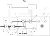
- the Fig. 6 shows a genset that is electrically connectable or connected to an energy supply network 23 with an internal combustion engine 1 according to the invention, which is coupled to an electric generator 8 by means of a mechanical clutch 24.
- the engine control device 3 is a target value NO x , Tar for an average NO x value resulting from a predeterminable or predetermined time period t av at an outlet point 7 of the exhaust gas aftertreatment device 16 NO x the NO x content of the exhaust gases can be specified or is given.
- the engine control device 3 is, at least during the time period t av , in an operating mode in which it is configured to continuously take into account the NO x components already emitted and the predefinable or predefined target value NO x , Tar to calculate a NO x reference value NO x,Ref ( t ) for the catalyst control device (6), which is selected such that at the end of the predeterminable or predetermined time period t av at the outlet point of the exhaust gas aftertreatment device 16 the predeterminable or predetermined target value NO x , Tar and to supply the calculated NO x reference value NO x,Ref ( t ) to the catalyst control device 6 as the NO x setpoint.
- FIG. 2 shows a typical operating case in which Fig. 1 illustrated embodiment of an internal combustion engine 1 according to the invention, here starting from a start of the internal combustion engine 1 by actuating a start button at time t 1 .
- the starting process is therefore completed at time t 3 (here, for example, about 5 minutes).
- the NO x proportions NO x,in the exhaust gases produced in the engine block 5 fall to a first value which is constant for the remainder of the start time t start .
- the noticeable drop in the NO x content NO x in the exhaust gases that is generated in the engine block 5 after the start-up process has ended is due to the fact that the engine control device 3 is configured to increase the boost pressure of the engine block 5 for a predeterminable or predetermined period of time after the internal combustion engine 1 has reached a nominal power and/or to retard the ignition timing of the piston-cylinder units (see also the combustion diagram of the Fig. 4 ).
- the engine control device 3 monitors a conversion rate R conv (t) of the exhaust gas aftertreatment device as an absolute value or - preferably - relative to an expected target value.
- R conv (t) a conversion rate of the exhaust gas aftertreatment device as an absolute value or - preferably - relative to an expected target value.
- the SCR catalyst 4 begins to operate because the temperature necessary for the reduction of the NO x in the catalytic zone is reached and reducing agent is injected with a mass flow Redux through the injection device 15 (controlled by the catalyst control device 6) into the exhaust manifold 17.
- the conversion rate R conv (t) begins to increase starting from the value zero and the NO x proportions NO x,out of the exhaust gases at the exit point of the SCR catalyst 4 begin to deviate from the NO x proportions NO x,in (the expected target value of the conversion rate R conv (t) is only reached at time t 5 ).
- the engine control unit 3 begins to enrich the air-fuel mixture again and to set the ignition timing back to an earlier point (see also the combustion diagram of the Fig. 4 ). Therefore, the NO x content NO x,in increases again to the Value at time ts, but this can be accepted since the SCR catalyst 4 is now operating.
- the specified time period t av (here, for example, 30 minutes) has elapsed and the NO x reference value NO x,Ref ( t ) for the catalyst control device 6 has reached the specified target value NO x , Tar reached (compare Fig. 5 ).
- time t 6 (here 2 hours as an example) to time t 7 (here 24 hours as an example) shows that here a target value of 30 minutes NO x , Tar increased 24-hour target value NO x , Tar is accepted in order to minimize the consumption of reducing agent.
- Fig. 3 An optional control scheme is shown in which the engine control device 3 of the internal combustion engine 1 of the Fig. 1 in order to reduce the NO x proportion of the exhaust gases emitted by the internal combustion engine (1) during a start-up time, it is additionally configured to specify a power ramp (dotted line which coincides with the solid line over a large period of time) for the engine block 3 (here for the electrical power P el ) during the start-up time t start of the internal combustion engine 1 in a first time section, preferably after reaching a minimum power (time ts), until reaching a predetermined limit value for the power (time t 11 ) with a first, smaller gradient and to specify it in a second time section (from time t 11 ) until reaching a nominal power of the internal combustion engine 1 (at time t 3 ) with a second, larger gradient, wherein it is preferably provided that the larger gradient is calculated as a function of the remaining time (time period t 3 - t 11 ) until reaching the start-up time
- the solid line represents the actual power delivered. It can be seen that the engine block 5 can only follow the power ramp after overcoming the turbo lag, which takes most of the time period t 9 - t 8 .
- a power ramp without the optional control scheme is shown in dashed form. It can be seen that a steeper power ramp is selected from the outset, which leads to increased NO x emissions during the turbo lag, which from the Time t 9 would have to be compensated by lowering the power ramp in order to achieve the specified NO x average value for the period t av NO x the NO x content of the exhaust gases.
- FIG. 4 A combustion diagram is shown in which it can be seen that the engine control device 3 of the internal combustion engine 1 of the Fig. 1 is optionally configured to move a current, first operating point 19 of the engine block 5, which is present after reaching a nominal power of the internal combustion engine 1, to a transient operating point 20 with lower NO x emissions (the NO x emissions generated in the engine block 5, for which straight lines with constant values are drawn, decrease in Fig. 4 decreases upwards), for example to an operating point with higher temperatures (the temperatures of the piston-cylinder units, for which straight lines with constant values are drawn, decrease in Fig. 4 towards the left), the exhaust gases immediately behind the exhaust valves of the piston-cylinder units (the engine control device 3 preferably uses the temperature T of the hottest piston-cylinder unit).
- the operating point In the combustion diagram (with the coordinate axes "excess air number ⁇ " and ignition timing measured at the "crankshaft angle ⁇ "), the operating point therefore moves within the knock limit and the misfire limit in the direction of higher exhaust gas temperatures.
- the engine control device controls and/or regulates the engine block such that the current operating point moves away from the transient operating point back towards the first operating point (preferably on the same trajectory as for the movement from the nominal operating point to the stationary operating point, only in the opposite direction) and reaches it.
- Fig. 5 shows again the most important parameters discussed above over time t. It is clearly visible how the time-dependent NO x reference value NO x,Ref ( t ) is increasingly approaching the specified target value NO x , Tar and finally reaches it at time t 2 (thick dot on the right). As an example, rectangles are drawn in grey for an earlier point in time (thick dot on the left), which show the average NO x content of the exhaust gases emitted by the internal combustion engine 1 up to this point in time and the amount of NO x required to achieve the specified target value. NO x , Tar still available average NO x contents of the exhaust gases.
- the synchronization duration is measured (here equal to: t 8 - t 1 ) and a decision is made depending on the synchronization duration (immediately after the time ts) whether the enrichment should be more or less pronounced, i.e. a desired excess air number ⁇ is determined depending on the synchronization duration.
Landscapes
- Engineering & Computer Science (AREA)
- Chemical & Material Sciences (AREA)
- Mechanical Engineering (AREA)
- General Engineering & Computer Science (AREA)
- Combustion & Propulsion (AREA)
- Chemical Kinetics & Catalysis (AREA)
- Toxicology (AREA)
- Health & Medical Sciences (AREA)
- Theoretical Computer Science (AREA)
- Signal Processing (AREA)
- Exhaust Gas After Treatment (AREA)
- Combined Controls Of Internal Combustion Engines (AREA)
- Electrical Control Of Air Or Fuel Supplied To Internal-Combustion Engine (AREA)
Claims (20)
- Moteur à combustion interne (1) avec :- un bloc moteur (5), avec une pluralité d'unités à pistons et cylindres (2), dans lesquelles en fonctionnement du moteur à combustion interne (1), un mélange air-carburant peut être brûlé en dégageant des gaz d'échappement contenant une fraction de NOx, dans lequel un dispositif de réglage de moteur (3) est prévu pour le réglage du fonctionnement du bloc moteur (5),- un dispositif de post-traitement de gaz d'échappement (16) pour le post-traitement des gaz d'échappement dégagés en fonctionnement pour la réduction au moins de la fraction de NOx, dans lequel le dispositif de post-traitement de gaz d'échappement (16) présente au moins un catalyseur SCR (4), et- un dispositif de réglage de catalyseur (6) pour la commande ou le réglage au moins d'au moins un catalyseur SCR (4),dans lequel au dispositif de réglage de moteur (3) est spécifiée une valeur cible (
NO x,Tar )pour une valeur moyenne de NOx (NO x ) obtenue par rapport à un intervalle (tav) prédéfini en un point de sortie (7) du dispositif de post-traitement de gaz d'échappement (16) de la fraction de NOx des gaz d'échappement, etdans lequel le dispositif de réglage de moteur (3) est configuré au moins dans un mode de fonctionnement afin de prendre en compte de manière cumulée les fractions de NOx des gaz d'échappement déjà émises depuis le début (t1) de l'intervalle (tav),caractérisé en ce que- le dispositif de réglage de moteur (3) est configuré afin de calculer en permanence au moins en prenant compte les fractions de NOx déjà émises depuis le début (t1) de l'intervalle (tav) et la valeur cible (NO x ,Tar ) prédéfinie une valeur de référence de NOx (NOx,Ref (t)) pour le dispositif de réglage de catalyseur (6) qui est choisie de sorte à obtenir à la fin de l'intervalle prédéfini (tav) au point de sortie du dispositif de post-traitement de gaz d'échappement (16) la valeur cible (NO x,Tar ) prédéfinie, et- la valeur de référence de NOx (NOx,Ref (t)) calculée est fournie au système de réglage de catalyseur (6) comme valeur de consigne de NOx. - Moteur à combustion interne selon la revendication 1, dans lequel le dispositif de réglage de moteur (3) est configuré afin de calculer la valeur de référence de NOx (NOx,Ref (t)) pour le système de réglage de catalyseur (6) en permanence selon la formule ci-après :

- Moteur à combustion interne selon l'une quelconque des revendications précédentes, dans lequel le dispositif de réglage de moteur (3) est configuré afin de prendre en compte aussi lors du réglage du bloc moteur (5), outre un état du bloc moteur (5), un état du dispositif de post-traitement de gaz d'échappement (16).
- Moteur à combustion interne selon la revendication précédente, dans lequel le dispositif de réglage de moteur (3) est configuré afin de prendre en compte l'état du dispositif de post-traitement de gaz d'échappement (16) sous la forme d'un taux de conversion actuel (R conv(t)).
- Moteur à combustion interne selon au moins l'une quelconque des revendications précédentes, dans lequel le dispositif de réglage de moteur (3) est configuré afin de commander et/ou de réguler - de préférence après expiration d'un temps de démarrage du moteur à combustion interne (1) - un point de fonctionnement actuel du bloc moteur (5) en fonction d'un taux de conversion Rconv (t) du dispositif de post-traitement de gaz d'échappement (16).
- Moteur à combustion interne selon la revendication précédente, dans lequel le dispositif de réglage de moteur (3) est configuré afin de déplacer un point de fonctionnement actuel du bloc moteur (5) d'un premier point de fonctionnement (19) à un point de fonctionnement (20) transitoire avec de plus faibles émissions de NOx au cas où l'au moins un catalyseur SCR (4) du dispositif de post-traitement de gaz d'échappement (16) réduit moins de fractions de NOx qu'il n'est requis pour l'obtention de la valeur de référence de NOx (NOx,Ref(t)) au point de sortie du dispositif de post-traitement de gaz d'échappement (16).
- Moteur à combustion interne selon au moins l'une quelconque des revendications précédentes, dans lequel le dispositif de réglage de moteur (3) est configuré afin de prendre en compte une puissance réelle mécanique (Pm,ist) du moteur à combustion interne (1) ou une puissance réelle électrique (Pel,ist) d'un générateur (8) électrique couplé au moteur à combustion interne (1) lors du réglage du bloc moteur (5) et du dispositif de réglage de catalyseur (6).
- Moteur à combustion interne selon au moins l'une quelconque des revendications précédentes, dans lequel un dispositif d'injection (5) pour l'injection d'agent de réduction dans une conduite de collecte de gaz d'échappement (17) est prévu avant une zone catalytique d'au moins un catalyseur SCR (4) et le dispositif de réglage de catalyseur (6) commande ou règle une quantité (Redux) d'agent de réduction transférée dans au moins un catalyseur SCR (4).
- Moteur à combustion interne selon au moins l'une quelconque des revendications précédentes, dans lequel le dispositif de réglage de moteur (3) est configuré pour la réduction de la fraction de NOx émise pendant un temps de démarrage du moteur à combustion interne (1) afin de prédéfinir pendant le temps de démarrage du moteur à combustion interne (1) une rampe de puissance pour le bloc moteur dans une première section temporelle, de préférence après l'obtention d'une puissance minimale, jusqu'à l'atteinte d'une valeur limite prédéfinie pour la puissance avec une première pente plus faible et de prédéfinir dans une deuxième section temporelle jusqu'à l'obtention d'une puissance nominale du moteur à combustion interne (1) avec une deuxième pente plus grande, dans lequel il est de préférence prévu que la pente plus grande soit calculée en fonction du temps restant jusqu'à l'obtention du temps de démarrage.
- Moteur à combustion interne selon au moins l'une quelconque des revendications précédentes, dans lequel le dispositif de réglage de moteur (3) est configuré pour la réduction de la fraction de NOx de gaz d'échappement émise pendant un temps de démarrage du moteur à combustion interne (1) afin d'augmenter dans le temps de démarrage du moteur à combustion interne (1) un coefficient d'excédent d'air (λ) du mélange air-carburant se trouvant à disposition pour la combustion dans les unités à pistons et cylindres d'une première valeur plus faible (λ1) à une deuxième valeur plus élevée (λ2).
- Moteur à combustion interne selon au moins l'une quelconque des revendications précédentes, dans lequel le dispositif de réglage de moteur (3) est configuré après l'obtention d'une puissance nominale du moteur à combustion interne (1) pour un intervalle prédéfinissable ou prédéfini afin de- diminuer une pression de charge du bloc moteur (5) et/ou- de retarder un moment de l'allumage dans les unités à pistons et cylindres.
- Moteur à combustion interne selon au moins l'une quelconque des revendications précédentes, dans lequel l'intervalle (tav) prédéfinissable ou prédéfini commence à s'écouler- avec un démarrage du moteur à combustion interne (1), de préférence avec une durée de 30 minutes et/ou- à un moment déterminé après une synchronisation du groupe électrogène avec un réseau d'alimentation en énergie ou pendant la rampe de puissance du moteur à combustion interne et/ou- après l'obtention de la puissance nominale du moteur à combustion interne (1) en présence d'une modification de charge.
- Moteur à combustion interne selon au moins l'une quelconque des revendications précédentes, dans lequel le dispositif de réglage de moteur (3) est configuré afin de ne pas dépasser une valeur limite prédéfinie ou prédéfinissable - éventuellement en fonction du temps -, dépendant en particulier du type de fonctionnement pour un courant de masse momentané ou pour une concentration momentanée des fractions de NOx des gaz d'échappement dans une conduite de collecte de gaz d'échappement (17).
- Moteur à combustion interne selon au moins l'une quelconque des revendications précédentes, dans lequel des capteurs sont prévus, par le biais desquels le dispositif de réglage de moteur (3) peut obtenir ou déterminer des informations sur l'état du bloc moteur (5) et l'état du dispositif de post-traitement de gaz d'échappement (16), de préférence au moins un capteur de NOx (12) et/ou un capteur de température (13).
- Moteur à combustion interne selon au moins l'une quelconque des revendications précédentes, dans lequel le dispositif de réglage de moteur (3) est configuré afin d'entreprendre une adaptation de conversions et/ou de fractions de NOx des gaz d'échappement pour obtenir une optimisation de l'agent de réduction et/ou d'une consommation des ressources globale, de préférence de l'urée et du gaz propulseur.
- Moteur à combustion interne selon au moins l'une quelconque des revendications précédentes, dans lequel le dispositif de réglage de moteur (3) est configuré afin de commander pour la régulation des émissions de NOx une pression de charge du bloc moteur (5) de sorte à obtenir un coefficient d'excédent d'air (X) souhaité.
- Moteur à combustion interne selon au moins l'une quelconque des revendications précédentes, dans lequel le dispositif de réglage de moteur (3) est configuré afin de prendre en compte lors du choix d'un coefficient d'excédent d'air (X) souhaité une durée de synchronisation d'un groupe électrogène contenant le moteur à combustion interne (1) avec un réseau d'alimentation en énergie.
- Moteur à combustion interne selon au moins l'une quelconque des revendications précédentes, dans lequel le dispositif de post-traitement de gaz d'échappement présente au moins un catalyseur d'oxydation (14) qui est monté en amont ou en aval de préférence en écoulement de l'au moins un catalyseur SCR (4).
- Moteur à combustion interne selon au moins l'une quelconque des revendications précédentes, dans lequel le dispositif de réglage de moteur (3) et le dispositif de réglage de catalyseur (6) sont réalisés dans un dispositif de réglage commun.
- Groupe électrogène avec un moteur à combustion interne (1) selon au moins l'une quelconque des revendications précédentes et un générateur (8) électrique couplé ou pouvant être couplé au moyen d'un couplage mécanique (24) au moteur à combustion interne (1).
Applications Claiming Priority (1)
| Application Number | Priority Date | Filing Date | Title |
|---|---|---|---|
| PCT/AT2018/060312 WO2020124101A1 (fr) | 2018-12-20 | 2018-12-20 | Moteur à combustion interne avec post-traitement des gaz d'échappement et commande des émissions d'oxyde d'azote |
Publications (3)
| Publication Number | Publication Date |
|---|---|
| EP3899231A1 EP3899231A1 (fr) | 2021-10-27 |
| EP3899231C0 EP3899231C0 (fr) | 2024-11-13 |
| EP3899231B1 true EP3899231B1 (fr) | 2024-11-13 |
Family
ID=64948993
Family Applications (1)
| Application Number | Title | Priority Date | Filing Date |
|---|---|---|---|
| EP18829716.2A Active EP3899231B1 (fr) | 2018-12-20 | 2018-12-20 | Moteur à combustion interne avec post-traitement des gaz d'échappement et commande des émissions d'oxyde d'azote |
Country Status (4)
| Country | Link |
|---|---|
| US (2) | US11391231B2 (fr) |
| EP (1) | EP3899231B1 (fr) |
| CA (1) | CA3123302C (fr) |
| WO (1) | WO2020124101A1 (fr) |
Families Citing this family (3)
| Publication number | Priority date | Publication date | Assignee | Title |
|---|---|---|---|---|
| US20250320839A1 (en) * | 2022-05-27 | 2025-10-16 | Cummins Power Generation Inc. | Control system for internal combustion engine, internal combustion engine configured to control combusion, and method of control thereof |
| US11773798B1 (en) * | 2022-12-01 | 2023-10-03 | Caterpillar Inc. | Controlling operation of an engine based on emissions monitoring |
| CN116838458B (zh) * | 2023-06-16 | 2025-10-21 | 中国船舶集团有限公司第七一一研究所 | 一种scr闭环控制装置及控制方法 |
Family Cites Families (22)
| Publication number | Priority date | Publication date | Assignee | Title |
|---|---|---|---|---|
| AT384279B (de) | 1986-03-05 | 1987-10-27 | Jenbacher Werke Ag | Einrichtung zur regelung des verbrennungsluftverh|ltnisses bei einem gasmotor mit magerer betriebsweise |
| DE19926146A1 (de) * | 1999-06-09 | 2000-12-14 | Volkswagen Ag | Verfahren zur Initiierung und Überwachung einer Entschwefelung von wenigstens einem in einem Abgaskanal einer Verbrennungskraftmaschine angeordneten NOx-Speicherkatalysator |
| JP4354068B2 (ja) * | 2000-02-02 | 2009-10-28 | 本田技研工業株式会社 | 内燃機関の排ガスの空燃比制御装置 |
| US6499293B1 (en) * | 2000-03-17 | 2002-12-31 | Ford Global Technologies, Inc. | Method and system for reducing NOx tailpipe emissions of a lean-burn internal combustion engine |
| DE102007006489B4 (de) * | 2007-02-09 | 2018-10-04 | Robert Bosch Gmbh | Verfahren zur Diagnose eines in einem Abgasbereich einer Brennkraftmaschine angeordneten Abgassensors und Vorrichtung zur Durchführung des Verfahrens |
| JP4830912B2 (ja) * | 2007-03-05 | 2011-12-07 | トヨタ自動車株式会社 | 内燃機関の制御装置 |
| US8156729B2 (en) | 2007-12-20 | 2012-04-17 | Detroit Diesel Corporation | Variable engine out emission control roadmap |
| DE102009055082A1 (de) * | 2009-12-21 | 2011-06-22 | Robert Bosch GmbH, 70469 | Verfahren zur Überwachung einer Schadstoff-Konvertierungsfähigkeit in einem Abgasnachbehandlungssystem |
| GB2480465A (en) * | 2010-05-19 | 2011-11-23 | Gm Global Tech Operations Inc | Method of controlling injection of diesel exhaust fluid |
| US9080488B2 (en) * | 2011-03-24 | 2015-07-14 | Ford Global Technologies, Llc | Method for estimating slippage of a selective catalyst reduction system |
| WO2012138936A1 (fr) * | 2011-04-05 | 2012-10-11 | Cummins Inc. | Système, procédé, et appareil pour surveillance de système de post-traitement |
| JP5817342B2 (ja) | 2011-08-29 | 2015-11-18 | トヨタ自動車株式会社 | 内燃機関の制御目標値設定方法及び内燃機関の制御装置 |
| EP2761154A4 (fr) * | 2011-09-28 | 2016-01-06 | Continental Controls Corp | Système et procédé de réglage automatique de point de consigne pour système de régulation du rapport air-carburant d'un moteur |
| AT512760B1 (de) | 2012-03-21 | 2014-05-15 | Avl List Gmbh | Verfahren zum Betreiben einer Brennkraftmaschine |
| US9371766B2 (en) * | 2012-09-14 | 2016-06-21 | Ford Global Technologies, Llc | Engine-on time predictor for aftertreatment scheduling for a vehicle |
| US9890678B2 (en) * | 2013-10-03 | 2018-02-13 | Baohua Qi | Multi-stage SCR control and diagnostic system |
| JP6015629B2 (ja) * | 2013-11-01 | 2016-10-26 | トヨタ自動車株式会社 | 内燃機関の制御装置 |
| JP6248789B2 (ja) * | 2014-05-08 | 2017-12-20 | いすゞ自動車株式会社 | 排気浄化システム |
| DE102015212697B4 (de) * | 2015-07-07 | 2020-07-30 | Mtu Friedrichshafen Gmbh | Verfahren zum Betreiben eines Abgasnachbehandlungssystems mit einem SCR-Katalysator, Steuereinrichtung für ein solches Abgasnachbehandlungssystem, Abgasnachbehandlungssystem und Brennkraftmaschine |
| US20160252036A1 (en) * | 2016-05-10 | 2016-09-01 | Caterpillar Inc. | System and method for controlling air-fuel ratio |
| FR3062162A1 (fr) | 2017-01-24 | 2018-07-27 | Peugeot Citroen Automobiles Sa | Procede d'activation d'un mode de combustion d'un moteur favorisant la thermique a l'echappement en cours de roulage |
| CN107914860B (zh) | 2017-10-26 | 2024-03-15 | 上海宏华海洋油气装备有限公司 | 智能液化天然气发电船 |
-
2018
- 2018-12-20 EP EP18829716.2A patent/EP3899231B1/fr active Active
- 2018-12-20 US US17/416,499 patent/US11391231B2/en active Active
- 2018-12-20 CA CA3123302A patent/CA3123302C/fr active Active
- 2018-12-20 WO PCT/AT2018/060312 patent/WO2020124101A1/fr not_active Ceased
-
2022
- 2022-07-19 US US17/868,593 patent/US11898514B2/en active Active
Also Published As
| Publication number | Publication date |
|---|---|
| US20220042475A1 (en) | 2022-02-10 |
| US20220403793A1 (en) | 2022-12-22 |
| CA3123302A1 (fr) | 2020-06-25 |
| EP3899231C0 (fr) | 2024-11-13 |
| US11391231B2 (en) | 2022-07-19 |
| CA3123302C (fr) | 2023-10-03 |
| EP3899231A1 (fr) | 2021-10-27 |
| US11898514B2 (en) | 2024-02-13 |
| WO2020124101A1 (fr) | 2020-06-25 |
Similar Documents
| Publication | Publication Date | Title |
|---|---|---|
| EP1576268B1 (fr) | Procede pour chauffer un catalyseur d'un moteur a combustion interne a injection directe de carburant | |
| AT516134B1 (de) | Brennkraftmaschine mit einer Regeleinrichtung | |
| DE102011011371B4 (de) | Adaptive Dieselmotorsteuerung bei Cetanzahlschwankungen | |
| AT511001B1 (de) | Verfahren zum betreiben einer über wenigstens zwei zylinder verfügenden brennkraftmaschine | |
| EP3899231B1 (fr) | Moteur à combustion interne avec post-traitement des gaz d'échappement et commande des émissions d'oxyde d'azote | |
| DE4407475A1 (de) | Verfahren und Vorrichtung zur Steuerung eines Fahrzeugs | |
| DE112011102184B4 (de) | Motorsteuergerät und Steuerverfahren | |
| DE102016222108A1 (de) | Verfahren zum Einstellen eines Kraftstoff/Luft-Verhältnisses eines Verbrennungsmotors | |
| AT506472B1 (de) | Brennkraftmaschine | |
| WO2011000640A1 (fr) | Procédé et dispositif permettant de faire fonctionner un moteur à combustion interne | |
| DE4106308C2 (de) | Verfahren und Vorrichtung zur Temperaturregelung für eine Abgassonde | |
| DE102016218818B4 (de) | Sekundärluftabhängige Lambdaregelung | |
| EP2071160A2 (fr) | Procédé de commande destiné à l'augmentation temporaire de la température de gaz d'échappement | |
| DE19626783A1 (de) | Motorsteuersystem | |
| EP1377738A1 (fr) | Procedes de commande du dosage de carburant en mode d'injection multiple | |
| AT517216B1 (de) | Brennkraftmaschine mit einer Regeleinrichtung | |
| DE102007000046B4 (de) | Steuersystem für eine Selbstzündungsbrennkraftmaschine | |
| EP2396528A2 (fr) | Procédé de régulation d'un moteur à combustion interne | |
| DE102010027970A1 (de) | Verfahren zum Betreiben eines Verbrennungsmotors | |
| DE10210550A1 (de) | Verfahren zum Betrieb einer Brennkraftmaschine | |
| DE102011055275B4 (de) | Verfahren zur Regelung der Abgastemperatur einer direkteinspritzenden Brennkraftmaschine | |
| DE102014005986B4 (de) | Betriebsverfahren für einen Magergasmotor und Magergasmotor | |
| DE102015207273A1 (de) | Motorsteuerung | |
| DE102011121100B4 (de) | Verfahren zum Betreiben eines Verbrennungsmotors mit einem Kraftstoffeinspritzsystem mit zumindest zwei Einspritzvorrichtungen | |
| EP3935272B1 (fr) | Moteur à combustion interne et procédé de fonctionnement d'un moteur à combustion interne |
Legal Events
| Date | Code | Title | Description |
|---|---|---|---|
| STAA | Information on the status of an ep patent application or granted ep patent |
Free format text: STATUS: UNKNOWN |
|
| STAA | Information on the status of an ep patent application or granted ep patent |
Free format text: STATUS: THE INTERNATIONAL PUBLICATION HAS BEEN MADE |
|
| PUAI | Public reference made under article 153(3) epc to a published international application that has entered the european phase |
Free format text: ORIGINAL CODE: 0009012 |
|
| STAA | Information on the status of an ep patent application or granted ep patent |
Free format text: STATUS: REQUEST FOR EXAMINATION WAS MADE |
|
| 17P | Request for examination filed |
Effective date: 20210714 |
|
| AK | Designated contracting states |
Kind code of ref document: A1 Designated state(s): AL AT BE BG CH CY CZ DE DK EE ES FI FR GB GR HR HU IE IS IT LI LT LU LV MC MK MT NL NO PL PT RO RS SE SI SK SM TR |
|
| DAV | Request for validation of the european patent (deleted) | ||
| DAX | Request for extension of the european patent (deleted) | ||
| P01 | Opt-out of the competence of the unified patent court (upc) registered |
Effective date: 20230614 |
|
| STAA | Information on the status of an ep patent application or granted ep patent |
Free format text: STATUS: EXAMINATION IS IN PROGRESS |
|
| 17Q | First examination report despatched |
Effective date: 20240328 |
|
| REG | Reference to a national code |
Ref country code: DE Ref legal event code: R079 Ipc: F02D0041140000 Ref country code: DE Ref legal event code: R079 Ref document number: 502018015331 Country of ref document: DE Free format text: PREVIOUS MAIN CLASS: F02D0041000000 Ipc: F02D0041140000 |
|
| RIC1 | Information provided on ipc code assigned before grant |
Ipc: F02D 29/06 20060101ALN20240611BHEP Ipc: F02D 41/06 20060101ALN20240611BHEP Ipc: F01N 9/00 20060101ALN20240611BHEP Ipc: F01N 13/00 20100101ALN20240611BHEP Ipc: F01N 3/10 20060101ALN20240611BHEP Ipc: F02P 5/15 20060101ALI20240611BHEP Ipc: F01N 3/20 20060101ALI20240611BHEP Ipc: F02D 41/00 20060101ALI20240611BHEP Ipc: F02D 41/14 20060101AFI20240611BHEP |
|
| GRAP | Despatch of communication of intention to grant a patent |
Free format text: ORIGINAL CODE: EPIDOSNIGR1 |
|
| STAA | Information on the status of an ep patent application or granted ep patent |
Free format text: STATUS: GRANT OF PATENT IS INTENDED |
|
| RIC1 | Information provided on ipc code assigned before grant |
Ipc: F02D 29/06 20060101ALN20240717BHEP Ipc: F02D 41/06 20060101ALN20240717BHEP Ipc: F01N 9/00 20060101ALN20240717BHEP Ipc: F01N 13/00 20100101ALN20240717BHEP Ipc: F01N 3/10 20060101ALN20240717BHEP Ipc: F02P 5/15 20060101ALI20240717BHEP Ipc: F01N 3/20 20060101ALI20240717BHEP Ipc: F02D 41/00 20060101ALI20240717BHEP Ipc: F02D 41/14 20060101AFI20240717BHEP |
|
| INTG | Intention to grant announced |
Effective date: 20240731 |
|
| GRAS | Grant fee paid |
Free format text: ORIGINAL CODE: EPIDOSNIGR3 |
|
| GRAA | (expected) grant |
Free format text: ORIGINAL CODE: 0009210 |
|
| STAA | Information on the status of an ep patent application or granted ep patent |
Free format text: STATUS: THE PATENT HAS BEEN GRANTED |
|
| AK | Designated contracting states |
Kind code of ref document: B1 Designated state(s): AL AT BE BG CH CY CZ DE DK EE ES FI FR GB GR HR HU IE IS IT LI LT LU LV MC MK MT NL NO PL PT RO RS SE SI SK SM TR |
|
| REG | Reference to a national code |
Ref country code: GB Ref legal event code: FG4D Free format text: NOT ENGLISH |
|
| REG | Reference to a national code |
Ref country code: CH Ref legal event code: EP |
|
| REG | Reference to a national code |
Ref country code: DE Ref legal event code: R096 Ref document number: 502018015331 Country of ref document: DE |
|
| REG | Reference to a national code |
Ref country code: IE Ref legal event code: FG4D Free format text: LANGUAGE OF EP DOCUMENT: GERMAN |
|
| U01 | Request for unitary effect filed |
Effective date: 20241204 |
|
| P04 | Withdrawal of opt-out of the competence of the unified patent court (upc) registered |
Free format text: CASE NUMBER: APP_65299/2024 Effective date: 20241210 |
|
| U07 | Unitary effect registered |
Designated state(s): AT BE BG DE DK EE FI FR IT LT LU LV MT NL PT RO SE SI Effective date: 20241213 |
|
| U20 | Renewal fee for the european patent with unitary effect paid |
Year of fee payment: 7 Effective date: 20241230 |
|
| PG25 | Lapsed in a contracting state [announced via postgrant information from national office to epo] |
Ref country code: HR Free format text: LAPSE BECAUSE OF FAILURE TO SUBMIT A TRANSLATION OF THE DESCRIPTION OR TO PAY THE FEE WITHIN THE PRESCRIBED TIME-LIMIT Effective date: 20241113 Ref country code: IS Free format text: LAPSE BECAUSE OF FAILURE TO SUBMIT A TRANSLATION OF THE DESCRIPTION OR TO PAY THE FEE WITHIN THE PRESCRIBED TIME-LIMIT Effective date: 20250313 |
|
| PG25 | Lapsed in a contracting state [announced via postgrant information from national office to epo] |
Ref country code: ES Free format text: LAPSE BECAUSE OF FAILURE TO SUBMIT A TRANSLATION OF THE DESCRIPTION OR TO PAY THE FEE WITHIN THE PRESCRIBED TIME-LIMIT Effective date: 20241113 |
|
| PG25 | Lapsed in a contracting state [announced via postgrant information from national office to epo] |
Ref country code: NO Free format text: LAPSE BECAUSE OF FAILURE TO SUBMIT A TRANSLATION OF THE DESCRIPTION OR TO PAY THE FEE WITHIN THE PRESCRIBED TIME-LIMIT Effective date: 20250213 |
|
| PG25 | Lapsed in a contracting state [announced via postgrant information from national office to epo] |
Ref country code: GR Free format text: LAPSE BECAUSE OF FAILURE TO SUBMIT A TRANSLATION OF THE DESCRIPTION OR TO PAY THE FEE WITHIN THE PRESCRIBED TIME-LIMIT Effective date: 20250214 |
|
| PG25 | Lapsed in a contracting state [announced via postgrant information from national office to epo] |
Ref country code: PL Free format text: LAPSE BECAUSE OF FAILURE TO SUBMIT A TRANSLATION OF THE DESCRIPTION OR TO PAY THE FEE WITHIN THE PRESCRIBED TIME-LIMIT Effective date: 20241113 |
|
| PG25 | Lapsed in a contracting state [announced via postgrant information from national office to epo] |
Ref country code: RS Free format text: LAPSE BECAUSE OF FAILURE TO SUBMIT A TRANSLATION OF THE DESCRIPTION OR TO PAY THE FEE WITHIN THE PRESCRIBED TIME-LIMIT Effective date: 20250213 |
|
| PG25 | Lapsed in a contracting state [announced via postgrant information from national office to epo] |
Ref country code: SM Free format text: LAPSE BECAUSE OF FAILURE TO SUBMIT A TRANSLATION OF THE DESCRIPTION OR TO PAY THE FEE WITHIN THE PRESCRIBED TIME-LIMIT Effective date: 20241113 |
|
| PG25 | Lapsed in a contracting state [announced via postgrant information from national office to epo] |
Ref country code: SK Free format text: LAPSE BECAUSE OF FAILURE TO SUBMIT A TRANSLATION OF THE DESCRIPTION OR TO PAY THE FEE WITHIN THE PRESCRIBED TIME-LIMIT Effective date: 20241113 |
|
| PG25 | Lapsed in a contracting state [announced via postgrant information from national office to epo] |
Ref country code: CZ Free format text: LAPSE BECAUSE OF FAILURE TO SUBMIT A TRANSLATION OF THE DESCRIPTION OR TO PAY THE FEE WITHIN THE PRESCRIBED TIME-LIMIT Effective date: 20241113 |
|
| REG | Reference to a national code |
Ref country code: CH Ref legal event code: PL |
|
| PG25 | Lapsed in a contracting state [announced via postgrant information from national office to epo] |
Ref country code: MC Free format text: LAPSE BECAUSE OF FAILURE TO SUBMIT A TRANSLATION OF THE DESCRIPTION OR TO PAY THE FEE WITHIN THE PRESCRIBED TIME-LIMIT Effective date: 20241113 |
|
| PLBE | No opposition filed within time limit |
Free format text: ORIGINAL CODE: 0009261 |
|
| STAA | Information on the status of an ep patent application or granted ep patent |
Free format text: STATUS: NO OPPOSITION FILED WITHIN TIME LIMIT |
|
| PG25 | Lapsed in a contracting state [announced via postgrant information from national office to epo] |
Ref country code: CH Free format text: LAPSE BECAUSE OF NON-PAYMENT OF DUE FEES Effective date: 20241231 |
|
| 26N | No opposition filed |
Effective date: 20250814 |
|
| PG25 | Lapsed in a contracting state [announced via postgrant information from national office to epo] |
Ref country code: IE Free format text: LAPSE BECAUSE OF NON-PAYMENT OF DUE FEES Effective date: 20241220 |
|
| U20 | Renewal fee for the european patent with unitary effect paid |
Year of fee payment: 8 Effective date: 20251119 |
|
| PGFP | Annual fee paid to national office [announced via postgrant information from national office to epo] |
Ref country code: GB Payment date: 20251119 Year of fee payment: 8 |