EP3899253B1 - Procédé de détection de vibrations différentes d'une éolienne - Google Patents
Procédé de détection de vibrations différentes d'une éolienne Download PDFInfo
- Publication number
- EP3899253B1 EP3899253B1 EP19827678.4A EP19827678A EP3899253B1 EP 3899253 B1 EP3899253 B1 EP 3899253B1 EP 19827678 A EP19827678 A EP 19827678A EP 3899253 B1 EP3899253 B1 EP 3899253B1
- Authority
- EP
- European Patent Office
- Prior art keywords
- vibration
- generator
- tower
- wind turbine
- control
- Prior art date
- Legal status (The legal status is an assumption and is not a legal conclusion. Google has not performed a legal analysis and makes no representation as to the accuracy of the status listed.)
- Active
Links
Images


Classifications
-
- F—MECHANICAL ENGINEERING; LIGHTING; HEATING; WEAPONS; BLASTING
- F03—MACHINES OR ENGINES FOR LIQUIDS; WIND, SPRING, OR WEIGHT MOTORS; PRODUCING MECHANICAL POWER OR A REACTIVE PROPULSIVE THRUST, NOT OTHERWISE PROVIDED FOR
- F03D—WIND MOTORS
- F03D7/00—Controlling wind motors
- F03D7/02—Controlling wind motors the wind motors having rotation axis substantially parallel to the air flow entering the rotor
- F03D7/0296—Controlling wind motors the wind motors having rotation axis substantially parallel to the air flow entering the rotor to prevent, counteract or reduce noise emissions
-
- F—MECHANICAL ENGINEERING; LIGHTING; HEATING; WEAPONS; BLASTING
- F03—MACHINES OR ENGINES FOR LIQUIDS; WIND, SPRING, OR WEIGHT MOTORS; PRODUCING MECHANICAL POWER OR A REACTIVE PROPULSIVE THRUST, NOT OTHERWISE PROVIDED FOR
- F03D—WIND MOTORS
- F03D7/00—Controlling wind motors
- F03D7/02—Controlling wind motors the wind motors having rotation axis substantially parallel to the air flow entering the rotor
- F03D7/0298—Controlling wind motors the wind motors having rotation axis substantially parallel to the air flow entering the rotor to prevent, counteract or reduce vibrations
-
- F—MECHANICAL ENGINEERING; LIGHTING; HEATING; WEAPONS; BLASTING
- F03—MACHINES OR ENGINES FOR LIQUIDS; WIND, SPRING, OR WEIGHT MOTORS; PRODUCING MECHANICAL POWER OR A REACTIVE PROPULSIVE THRUST, NOT OTHERWISE PROVIDED FOR
- F03D—WIND MOTORS
- F03D13/00—Assembly, mounting or commissioning of wind motors; Arrangements specially adapted for transporting wind motor components
- F03D13/20—Arrangements for mounting or supporting wind motors; Masts or towers for wind motors
-
- F—MECHANICAL ENGINEERING; LIGHTING; HEATING; WEAPONS; BLASTING
- F03—MACHINES OR ENGINES FOR LIQUIDS; WIND, SPRING, OR WEIGHT MOTORS; PRODUCING MECHANICAL POWER OR A REACTIVE PROPULSIVE THRUST, NOT OTHERWISE PROVIDED FOR
- F03D—WIND MOTORS
- F03D17/00—Monitoring or testing of wind motors, e.g. diagnostics
- F03D17/009—Monitoring or testing of wind motors, e.g. diagnostics characterised by the purpose
- F03D17/013—Monitoring or testing of wind motors, e.g. diagnostics characterised by the purpose for detecting abnormalities or damage
- F03D17/014—Monitoring or testing of wind motors, e.g. diagnostics characterised by the purpose for detecting abnormalities or damage indicative of a fault or failure
-
- F—MECHANICAL ENGINEERING; LIGHTING; HEATING; WEAPONS; BLASTING
- F03—MACHINES OR ENGINES FOR LIQUIDS; WIND, SPRING, OR WEIGHT MOTORS; PRODUCING MECHANICAL POWER OR A REACTIVE PROPULSIVE THRUST, NOT OTHERWISE PROVIDED FOR
- F03D—WIND MOTORS
- F03D17/00—Monitoring or testing of wind motors, e.g. diagnostics
- F03D17/009—Monitoring or testing of wind motors, e.g. diagnostics characterised by the purpose
- F03D17/015—Monitoring or testing of wind motors, e.g. diagnostics characterised by the purpose for monitoring vibrations
-
- F—MECHANICAL ENGINEERING; LIGHTING; HEATING; WEAPONS; BLASTING
- F03—MACHINES OR ENGINES FOR LIQUIDS; WIND, SPRING, OR WEIGHT MOTORS; PRODUCING MECHANICAL POWER OR A REACTIVE PROPULSIVE THRUST, NOT OTHERWISE PROVIDED FOR
- F03D—WIND MOTORS
- F03D17/00—Monitoring or testing of wind motors, e.g. diagnostics
- F03D17/027—Monitoring or testing of wind motors, e.g. diagnostics characterised by the component being monitored or tested
- F03D17/034—Towers
-
- F—MECHANICAL ENGINEERING; LIGHTING; HEATING; WEAPONS; BLASTING
- F03—MACHINES OR ENGINES FOR LIQUIDS; WIND, SPRING, OR WEIGHT MOTORS; PRODUCING MECHANICAL POWER OR A REACTIVE PROPULSIVE THRUST, NOT OTHERWISE PROVIDED FOR
- F03D—WIND MOTORS
- F03D17/00—Monitoring or testing of wind motors, e.g. diagnostics
- F03D17/027—Monitoring or testing of wind motors, e.g. diagnostics characterised by the component being monitored or tested
- F03D17/036—Generators
-
- F—MECHANICAL ENGINEERING; LIGHTING; HEATING; WEAPONS; BLASTING
- F05—INDEXING SCHEMES RELATING TO ENGINES OR PUMPS IN VARIOUS SUBCLASSES OF CLASSES F01-F04
- F05B—INDEXING SCHEME RELATING TO WIND, SPRING, WEIGHT, INERTIA OR LIKE MOTORS, TO MACHINES OR ENGINES FOR LIQUIDS COVERED BY SUBCLASSES F03B, F03D AND F03G
- F05B2220/00—Application
- F05B2220/70—Application in combination with
- F05B2220/706—Application in combination with an electrical generator
- F05B2220/7066—Application in combination with an electrical generator via a direct connection, i.e. a gearless transmission
-
- F—MECHANICAL ENGINEERING; LIGHTING; HEATING; WEAPONS; BLASTING
- F05—INDEXING SCHEMES RELATING TO ENGINES OR PUMPS IN VARIOUS SUBCLASSES OF CLASSES F01-F04
- F05B—INDEXING SCHEME RELATING TO WIND, SPRING, WEIGHT, INERTIA OR LIKE MOTORS, TO MACHINES OR ENGINES FOR LIQUIDS COVERED BY SUBCLASSES F03B, F03D AND F03G
- F05B2270/00—Control
- F05B2270/30—Control parameters, e.g. input parameters
- F05B2270/334—Vibration measurements
-
- Y—GENERAL TAGGING OF NEW TECHNOLOGICAL DEVELOPMENTS; GENERAL TAGGING OF CROSS-SECTIONAL TECHNOLOGIES SPANNING OVER SEVERAL SECTIONS OF THE IPC; TECHNICAL SUBJECTS COVERED BY FORMER USPC CROSS-REFERENCE ART COLLECTIONS [XRACs] AND DIGESTS
- Y02—TECHNOLOGIES OR APPLICATIONS FOR MITIGATION OR ADAPTATION AGAINST CLIMATE CHANGE
- Y02E—REDUCTION OF GREENHOUSE GAS [GHG] EMISSIONS, RELATED TO ENERGY GENERATION, TRANSMISSION OR DISTRIBUTION
- Y02E10/00—Energy generation through renewable energy sources
- Y02E10/70—Wind energy
- Y02E10/72—Wind turbines with rotation axis in wind direction
-
- Y—GENERAL TAGGING OF NEW TECHNOLOGICAL DEVELOPMENTS; GENERAL TAGGING OF CROSS-SECTIONAL TECHNOLOGIES SPANNING OVER SEVERAL SECTIONS OF THE IPC; TECHNICAL SUBJECTS COVERED BY FORMER USPC CROSS-REFERENCE ART COLLECTIONS [XRACs] AND DIGESTS
- Y02—TECHNOLOGIES OR APPLICATIONS FOR MITIGATION OR ADAPTATION AGAINST CLIMATE CHANGE
- Y02E—REDUCTION OF GREENHOUSE GAS [GHG] EMISSIONS, RELATED TO ENERGY GENERATION, TRANSMISSION OR DISTRIBUTION
- Y02E10/00—Energy generation through renewable energy sources
- Y02E10/70—Wind energy
- Y02E10/728—Onshore wind turbines
Definitions
- the present invention relates to a method for detecting multiple vibrations of a wind turbine.
- the invention also relates to a method for operating a wind turbine in which multiple vibrations are detected.
- the present invention also relates to a wind turbine.
- Wind turbines are well known for generating electrical power from wind.
- faults can occur which are monitored to protect the wind turbine.
- One possible fault is excessive oscillation of the tower, namely in the area of the tower head and thus in the area of the wind turbine nacelle mounted on the tower head.
- Such oscillation can be caused by excitation by wind at a corresponding resonance frequency and can reach such high amplitudes that the wind turbine must be at least partially switched off to protect it.
- Such a tower oscillation which leads to a wind turbine being switched off, can also be triggered by an earthquake, for example. Even then, depending on the amplitude of the oscillation, the operation of the wind turbine can be stopped or at least interrupted. As soon as this strong oscillation is over, the wind turbine can be put back into operation, possibly fully automatically.
- an acceleration sensor can be placed on top of the nacelle of the wind turbine. It detects accelerations, which allows the tower movement to be calculated. This is described, for example, in the patent specification US$6,876,099 .
- Another possible problem could be mechanical vibration of the generator.
- the electrodynamic rotor of the generator rotates just as fast as the aerodynamic rotor, namely in the range of 5 to 20 rpm. If, for example, imbalances occur here, this can also pose a risk to the wind turbine. And here too, depending on such a detected vibration, a protective measure can be initiated, which in extreme cases can mean stopping the wind turbine.
- German Patent and Trademark Office has searched the following prior art in the priority application for the present application: EN 10 2007 011 835 A1 , EN 10 2016 203 013 A1 , US 6 876 099 B2 , US 2014 / 0 122 011 A1 , US 2017 / 0 306 926 A1 and US 2017 / 0 363 072 A1 . Further state of the art is in US 2006/066111 A1 disclosed.
- the present invention is therefore based on the object of at least one of the above-mentioned.
- a method according to claim 1 is proposed.
- a method for detecting several vibrations of a wind turbine is proposed. It is therefore about detecting mechanical vibrations of a wind turbine and a wind turbine is used as a basis, which has a generator with a generator axis for generating electrical power from wind, as well as a nacelle for supporting the generator.
- a tower is provided for supporting the nacelle.
- a tower vibration is detected with a vibration sensor and a Fault-induced mechanical generator vibration is detected with the same vibration sensor.
- a mechanical generator oscillation caused by electrical faults is one in which an irregularity in the electrical field occurs, for example due to a partial short circuit or other electrical fault. This causes the generator to no longer run smoothly, which can also be referred to as uneven running. Such uneven running caused by an electrical fault is different from uneven running due to an imbalance.
- An imbalance leads to a periodic load with a frequency corresponding to the rotor speed, whereas a mechanical generator oscillation caused by electrical faults can lead to a load with a higher frequency.
- a mechanical generator oscillation caused by electrical faults can also lead to a more jerky movement, whereas an imbalance leads to an essentially sinusoidal load curve or a sinusoidal oscillating movement.
- the operation of the wind turbine takes into account the detected tower vibration and the detected mechanical generator vibration.
- the control of the wind turbine is carried out depending on the detected tower vibration and the detected generator vibration.
- a generator speed can be adjusted depending on the detected tower vibration as well as the detected generator vibration.
- the tower vibration can be related to the mechanical generator vibration.
- the mechanical generator vibration triggered by at least one electrical fault can stimulate a tower vibration, even if it is only half the frequency of the generator vibration.
- systematic measurement errors particularly measurement delays, can be avoided or they become irrelevant, or at least less important, if they are present equally for both vibrations recorded. Such systematic errors can cancel each other out, especially when comparing both vibrations.
- phase shift between these two oscillations can be distorted by different measuring sensors. If the same measuring sensor is used, this problem does not generally exist.
- phase shift can also exist between the fundamental oscillation and one type of oscillation on the one hand and a harmonic of another type of oscillation on the other.
- An important consideration of the recorded tower vibration and the recorded mechanical generator vibration when operating a wind turbine is to change the operating point of the wind turbine if necessary in the event of a fault that can be detected by these vibrations, in particular to change or reduce its speed, i.e. the speed of the aerodynamic rotor. Reducing the speed to zero is also an option.
- the vibration sensor is designed as an acceleration sensor.
- the idea here is that a wear-free or low-wear sensor can be used because the measurement of the acceleration can be sufficient to detect a mechanical vibration.
- a wear-free or low-wear sensor can be used because the measurement of the acceleration can be sufficient to detect a mechanical vibration.
- not only a tower movement can be detected using an acceleration sensor, but also a generator vibration.
- the use of a strain gauge the measurement accuracy of which also depends on the quality of the fastening, can be avoided.
- both the tower vibration and the mechanical generator vibration can be recorded. In order to achieve this result of joint vibration recording with a strain gauge or strain sensor, one would have to be arranged in a position where both the generator vibration and the tower vibration lead to a strain.
- the acceleration sensor detects an acceleration in at least two directions, ideally in two directions that are orthogonal to one another. This allows any direction of vibration to be detected continuously, which is composed of these two detected vibrations that are orthogonal to one another.
- an acceleration sensor can record both directions of vibration at one and the same point and can thus detect the resulting or underlying common direction of vibration. It was also recognized that this is also possible individually for each of the two types of vibration, namely for both the tower vibration and the mechanical generator vibration. If the respective vibration is extracted from the signal in each direction recorded, i.e. the tower vibration on the one hand and the generator vibration on the other, a separate direction of vibration can be recognized for both the tower vibration and the generator vibration. Furthermore, any subsequent explanations of a generator vibration also basically relate to a mechanical generator vibration.
- the vibration sensor is arranged on the generator, in particular on a stator of the generator.
- a stator of the generator has only one stator and this vibration sensor can be It then records mechanical vibrations from the generator, as it is directly connected to the generator. At the same time, however, it also records tower vibrations, as the entire nacelle and thus the generator also vibrates with the tower.
- the position of the vibration sensor on the stator of the generator is therefore not only good for recording the mechanical generator vibration, but also for recording the tower vibration.
- the vibration sensor be arranged on a stator carrier that supports the stator of the generator.
- a stator carrier is also located in the immediate vicinity of the generator and can transmit generator vibrations well.
- Such a stator carrier can be arranged so rigidly and close to the stator that it can also be considered part of the stator.
- the vibration sensor would thus be arranged on the stator and at the same time on the stator carrier. The same advantageous effects therefore apply to this position as were explained above for the position on the stator of the generator.
- the vibration sensor in a front part of the nacelle and/or in an area in front of the tower axis.
- An arrangement on the stator of the generator and/or on the supporting stator carrier is in the front part of the nacelle in a gearless wind turbine, which is preferably proposed here.
- the front part of the nacelle is an area for aerodynamic Rotor. It is assumed here that the wind turbine is designed as a so-called windward rotor. In the same case of a leeward rotor, an arrangement in the rear part of the nacelle would be assumed.
- the area in front of the tower axis is therefore also an area in the front part of the nacelle, and arranging the sensor there has the same advantages as was explained for the arrangement in the front part of the nacelle.
- a longitudinal vibration signal and a transverse vibration signal are recorded.
- the longitudinal vibration signal is directed in a longitudinal direction of the generator axis and the transverse vibration signal is directed in a direction transverse to the longitudinal direction.
- both vibration directions are recorded in a horizontal plane.
- a tower vibration namely in particular a vibration of the tower head, takes place essentially in a horizontal plane.
- This vibration direction can then oscillate in one direction in this horizontal plane, for example from north to south or from northeast to southwest, to name just two clear examples. Of course, this vibration direction can also change.
- the generator can perform an oscillation in the sense of eccentricity, which leads to an oscillation or several oscillations perpendicular to the axis of rotation.
- a vertical oscillation direction can also occur in the generator as part of this.
- a quasi-eccentric oscillation i.e. an oscillation perpendicular to the axis of rotation of the generator, also has a horizontal component, but still perpendicular to the axis of rotation.
- an oscillation direction namely perpendicular to the axis of rotation, is dominant or is to be expected predominantly. This can be easily recorded by recording an oscillation in a horizontal direction, namely perpendicular to the axis of rotation.
- the generator can also have a vibration in the form of a tilting direction, which, however, is essentially recorded as a vibration in the longitudinal direction of the generator's axis of rotation, particularly in the area of the generator's air gap. This is then also a direction in a horizontal plane and transverse to the previously described direction of vibration, which is also formed in the horizontal plane but transverse to the longitudinal axis.
- At least one vibration signal recorded by the vibration sensor is separated into a tower vibration signal and a generator vibration signal depending on the frequency, whereby in particular a filter device is used and frequency components below a predeterminable cut-off frequency are used as the tower vibration signal and frequency components above the cut-off frequency are used as the generator vibration signal.
- a jointly recorded vibration signal can be divided into signal components of the tower vibration or the generator vibration by means of a simple frequency division.
- one recorded vibration signal can be a longitudinal vibration signal and another recorded vibration signal can be a transverse vibration signal.
- These signals can then be further processed, namely depending on whether they are assigned to the tower vibration or the generator vibration.
- the filter device can have a high-pass filter and a low-pass filter and it can be implemented as a digital filter device in a process computer.
- the generator oscillation be recorded in a frequency range of 2 to 20 Hz. It is therefore particularly advantageous to set a cut-off frequency in the range between 1.25 and 2 Hz. For example, a cut-off frequency of 1.5 Hz can be used as a basis.
- the separation frequency is specified depending on the current rotor speed and thus the generator speed.
- this frequency for separating tower vibration and generator vibration can depend on the speed of the rotor or generator.
- the frequency of the Generator vibration depends on the rotor speed, whereby the frequency of the tower vibration can depend particularly on a natural frequency of the tower, and less on the rotor speed.
- there is a larger frequency difference between the two types of vibration which can also make a change in the crossover frequency sensible.
- a longitudinal tower vibration and a transverse tower vibration are detected as at least one tower vibration.
- a longitudinal tower vibration is a vibration of the tower that is directed in the longitudinal direction of the generator axis.
- a transverse tower vibration is a vibration of the tower in a direction transverse to the generator axis, which also oscillates in a horizontal plane and is directed transverse to the tower axis.
- a longitudinal tower vibration which can also be referred to as a tower pitch vibration, is triggered in particular by the wind, namely by the fact that it acts on an aerodynamic rotor of the wind turbine.
- the aerodynamic rotor is also referred to simply as the rotor below.
- the transverse tower vibration can be caused particularly by an imbalance of the rotor.
- All three vibrations i.e. the mechanical generator vibration caused by at least one electrical fault, the longitudinal tower vibration and the transverse tower vibration, are recorded with the same vibration sensor. It was found that all three vibrations can still be distinguished. This is possible because the tower vibrations can be distinguished from the mechanical generator vibration by their different frequencies and the two tower vibrations can be distinguished from each other by their directions.
- control of the wind turbine is functionally divided into an operating point control and a protection control.
- both control areas are strictly separated from one another.
- the operating point control is designed to control the wind turbine at an operating point. It controls the wind turbine, particularly depending on the wind speed, at a speed appropriate to this wind speed and at a power output appropriate to this wind speed.
- This operating point control is a normal control. If the wind changes, this is recorded and the operating point can change accordingly, for example if the wind speed drops during partial load operation and the operating point changes to an operating point with a lower speed than before and a lower output power than before.
- the protection control is hierarchically superior to this operating point control and is intended to check the protective functions of the wind turbine.
- the hierarchical superiority means that the operating point control must be subordinate to the protection control. If the protection control specifies a different speed than the operating point control, particularly if the protection control specifies a reduction in the speed to zero, the operating point control must be subordinate to this and the speed that the operating point control would suggest will not be controlled. In particular, the speed specified up to that point by the operating point control will be abandoned.
- the protection control checks for fault criteria and, if a predetermined fault criterion is detected, takes over the operating point control and moves to a secured operating point depending on the detected fault criterion.
- a secured operating point can mean in particular that the rotation of the rotor of the wind turbine is reduced to zero. However, it can also mean that the wind turbine continues to operate at a lower speed.
- speed here basically refers to the rotor speed of the aerodynamic rotor, which, however, corresponds to the speed of the generator if a gearless wind turbine is used as a basis.
- the protection control can use one and the same vibration sensor for tower vibration monitoring and generator vibration monitoring, or evaluate information or signals from one and the same vibration sensor.
- a distinction is made between tower vibration and generator vibration, and different limit values are also used.
- it was recognized that the use of one and the same vibration sensor is still possible, thus enabling little effort in terms of providing the vibration sensor.
- the protective control is designed as a fail-safe control.
- the operating point control is not designed as a fail-safe control system.
- the idea behind this is that a complex fail-safe control system is only required for the protective control system. This means that the wind turbine can be controlled and managed via the operating point control system using complex control and regulation processes, without the need to ensure fail-safe operation with similar effort.
- the protective control has a main and a secondary control, wherein the main control carries out the protective control and the secondary control takes over the protective control or part thereof if the main control fails completely or partially. In this way, the said fail-safe control can be achieved.
- main control and the secondary control are carried out simultaneously. If the protective control takes over when a fault criterion is detected, it carries out the main control and the secondary control simultaneously so that they both control the safe operating point. This can mean, for example, that both initiate the shutdown of the wind turbine by both triggering a pre-programmed or otherwise prepared emergency adjustment of the rotor blades.
- the main control and the secondary control can be designed similarly or even identically or at least almost identically in order to thereby achieve redundancy.
- redundancy can also preferably be achieved by two different systems being able to achieve the same or similar things.
- the protection controller should do this using its main controller.
- the main controller can bring the rotor blades into their feathering position using a pre-programmed blade angle time profile. If the main controller of the protective control itself fails, the secondary controller can bring the rotor blades into the feathering position instead, but possibly in a simpler way, e.g. by providing the relevant pitch motors with a constant input voltage or current to thereby generate an essentially constant pitch torque with which the rotor blades are turned into the feathering position until they reach a mechanical limit switch.
- the operating point control does not need to be prepared for problems. If significant problems occur, the protection control, which is hierarchically superior to the operating point control, can take over. In such a fault, which generally occurs rarely, the operating point control is temporarily denied permission and ability to control and the protection control takes over until the detected fault is remedied and the wind turbine can and may operate normally again.
- a fault is detected, in particular that the protective control detects a fault, when the detected tower vibration exceeds a predetermined tower vibration limit value, in particular when a or the tower longitudinal vibration exceeds a predetermined tower longitudinal vibration limit value and/or a or the tower transverse vibration exceeds a predetermined tower transverse vibration limit value.
- the protection controller can also detect a fault if the detected generator vibration exceeds a predetermined generator vibration limit.
- a predetermined generator vibration limit it is proposed here to define the detected tower vibration to use the tower vibration amplitude of the respective tower vibration, and/or to consider an acceleration in each case, so that the respective vibration limit value represents a limit value of an acceleration.
- the generator vibration amplitude it is proposed here to use the generator vibration amplitude to consider the generator vibration.
- the acceleration of the generator vibration can be considered for this purpose.
- the tower vibration limit value, the tower longitudinal vibration limit value and the tower transverse vibration limit value are each different from the generator vibration limit value.
- the tower vibration limit value, the tower longitudinal vibration limit value and the tower transverse vibration limit value are each greater than the generator vibration limit value, in particular the tower vibration limit value, the tower longitudinal vibration limit value and the tower transverse vibration limit value are each at least five times as large as the generator vibration limit value.
- the vibration tolerance band therefore has a positive and a negative limit that the vibration should not exceed or fall below. If the limit is nevertheless exceeded or not reached, i.e. the tolerance band is left, the process begins to further observe and evaluate this exceedance or undershoot.
- the positive and negative limits preferably have the same value in terms of magnitude, in particular the generator vibration limit value or the tower vibration limit value, or the tower longitudinal vibration limit value or the tower transverse vibration limit value.
- the generator vibration limit value or the tower vibration limit value or the tower longitudinal vibration limit value or the tower transverse vibration limit value.
- several of these types of vibration can also be monitored simultaneously, in particular all three types of vibration simultaneously, and then the corresponding limit and thus the corresponding limit value is used in each case.
- a first and a second limit value can be specified for the generator vibration limit value and the tower vibration limit value, or the tower longitudinal vibration limit value and the tower transverse vibration limit value, wherein the first limit value can correspond to the limit of the first vibration tolerance band and the second limit value can correspond to the limit of a second vibration tolerance band described below.
- the first vibration tolerance band Every time the first vibration tolerance band is left, i.e. every time the limit is exceeded or undershot, it is recorded and integrated or summed up.
- the area between the vibration curve that exceeds or falls below the limit and the limit in question is integrated and compared with a predetermined maximum sum. It was recognized that instead of integrating such areas, it is usually sufficient to simply record the number of times the tolerance band is left, or exceeded or undershot, i.e. to just count the times it is left. In both cases, the result is compared with a predetermined maximum sum, the value of which is of course predetermined depending on whether integration or counting is used. If this maximum sum is reached or exceeded, it is assumed that there is a fault, and a fault is therefore recognized.
- the wind turbine is stopped when the fault is detected, which can be accompanied by the output of a corresponding error signal.
- a vibration warning i.e. a warning signal
- the wind turbine can initially continue to operate. However, the vibration behavior continues to be monitored.
- monitoring be carried out to see whether such a fault occurs again, and in particular how often or frequently it occurs.
- the integration or summation i.e. the counting
- the integration or summation can be reset so that it starts again from the beginning. This can be done by resetting the excess sum to zero. Then, as described above, a check can be made for a renewed fault by integrating or counting.
- a second test period is set that is longer than the first test period.
- the first test period can, for example, last between 5 hours and 2 days, in particular one day, while the second test period can last between 3 and 14 days, in particular 7 days.
- the predetermined warning limit can be in a range from 3 to 10, in particular around 5 or 6.
- the count of detected faults can also be reset, either reduced to zero or reduced by one counter at predetermined reduction intervals, which can be one day, for example. This can also reduce the counter to zero if, for example, it had risen to four but then no faults were detected for four days. The values are not reduced beyond zero into the negative.
- the test to see whether the number of vibration warnings has reached a predetermined warning number limit in the predetermined second test period can also be carried out by selecting the warning number limit and the duration of the reduction interval. If the warning number limit is, for example, 4 and the duration of the reduction interval is one day, the system will stop if 4 faults are detected in one day, 5 faults are detected in two days, 6 faults are detected in three days, or 7 faults are detected in four days. A maximum permissible number of 7 faults in four days can therefore be achieved by setting the warning number limit to 4 and the duration of the reduction interval to one day. In this case, a fault would still be detected even if one or a few fewer faults were detected in a shorter period of time, but this is an advantageous effect.
- a fault is detected and the wind turbine is stopped if the vibration curve leaves a second vibration tolerance band that is larger than the first tolerance band once.
- This second vibration tolerance band therefore has larger limits than the first vibration tolerance band. If it is left just once, the fault is so serious that the wind turbine is stopped immediately for its own protection, at least without further checking the vibration.
- the described monitoring of the vibration curve can be carried out independently for each described vibration type, whereby preferably different values are specified for the test criteria.
- the two-stage test for a disturbance is carried out only for the tower vibration, whereas a one-stage test is provided for the generator vibration.
- an acceleration curve is monitored as the oscillation curve.
- An acceleration curve can also be taken into account for the generator oscillation and thus an acceleration that has a magnitude should not exceed 2 g. Accordingly, a limit value can be set at 2 g, or preferably in the range of 1 to 2 g.
- tower vibrations in the longitudinal and transverse directions are recorded in the frequency range from 0.1 to 1.25 Hz.
- a crossover frequency be set to a value above 1.25 Hz.
- a value of 1.25 to 2 Hz is proposed as the crossover frequency.
- the maximum acceleration occurring in each case is recorded for the vibration being examined. This can preferably be done in the longitudinal and transverse directions.
- a limit value for both the longitudinal and transverse directions that corresponds in magnitude to twice the acceleration due to gravity, i.e. two g.
- a lower value in the range of 1 to 2 g is specified as the maximum acceleration in magnitude, and when this limit value is reached, the wind turbine is stopped, in particular the rotor blades are emergency adjusted to the feather position.
- a wind turbine is also proposed.
- a wind turbine comprises a generator having a generator axis for generating electrical power from wind, wherein the generator can be driven by an aerodynamic rotor with one or more rotor blades, a nacelle for operating the generator, a tower for supporting the nacelle, a vibration sensor for detecting a tower vibration, wherein the vibration sensor is also prepared for detecting a mechanical generator vibration, and a control device for controlling the wind turbine depending on the detected tower vibration and depending on the detected generator vibration.
- a wind turbine is therefore proposed which is based on the method described above, wherein the above method is implemented on the wind turbine according to at least one described embodiment.
- the control is implemented in the control device.
- the control device can be designed in particular as a process computer or implemented in a process computer of the wind turbine.
- the wind turbine is designed as a gearless wind turbine.
- the aerodynamic rotor therefore drives directly to the generator, namely its electrodynamic rotor, which is also referred to as the runner.
- the generator which is preferably designed as a synchronous generator, is a slowly rotating generator, in particular a multi-pole generator.
- a multi-pole generator is understood to be one that has at least 96 stator poles.
- Such a generator in a gearless wind turbine therefore also leads to a potential vibration spectrum that has higher frequencies than that of an expected tower vibration, but the spectrum, i.e. the frequency range in which vibrations are to be expected, is significantly closer to that of the expected tower vibrations.
- such a generator has a nominal speed of less than 20 rpm. This makes it significantly different from a generator of a geared wind turbine, whose speed can regularly be in the range of 1500 to 3000 rpm.
- the generator of a gearless wind turbine is usually arranged in an area in front of the tower of the wind turbine, at least in relation to the upper tower area. This means that a vibration sensor arranged in the area of the generator is also arranged in such an area.
- the vibration sensor is designed as an acceleration sensor and is prepared to detect an acceleration in at least two directions, in particular in two directions arranged essentially orthogonally to one another in a horizontal plane.
- the vibration sensor is arranged on the generator, in particular on a stator of the generator, on a generator support carrying the generator and/or in a front part of the nacelle.
- Figure 1 shows a wind turbine 100 with a tower 102 and a nacelle 104.
- a rotor 106 with three rotor blades 108 and a spinner 110 is arranged on the nacelle 104.
- the rotor 106 is set in rotation by the wind and thereby drives a generator in the nacelle 104.
- Figure 2 shows schematically a section of a wind turbine 200 with a nacelle 202 and a generator 204.
- the generator 204 has a stator 206 and a rotor 208.
- the rotor 208 is directly coupled to three rotor blades 210, which are only partially shown, only schematically and of which only two are shown, because the third rotor blade is located on the opposite side of the nacelle 202 in the position shown.
- the generator 204 is thus designed as an internal rotor and since this rotor 208 is directly connected to the rotor blades 210 and thus to the aerodynamic rotor 212, a gearless wind turbine is present.
- the rotor 208 then rotates during operation relative to the stator 206 and thereby about a generator axis 214.
- the generator axis 214 is thus also the axis of rotation of the rotor 212.
- any bearings are in Figure 2 not shown.
- the stator 206 is attached to a machine carrier 218 via a stator carrier 216.
- the machine carrier 218 is rotatably mounted on the tower 222 via an azimuth bearing 220.
- FIG. 2 also shows an enlarged detail 224.
- a vibration sensor 228 is shown, which is designed as an acceleration sensor. This vibration sensor 228 is arranged and fastened to the stator 206 and thus to the generator 204. The vibration sensor 228 is simultaneously arranged on the stator carrier 216.
- the vibration sensor 228 is arranged in a front part of the nacelle 202.
- the rotating part namely the so-called spinner 230
- spinner 230 is drawn significantly longer than usual.
- the front part 234 can be referred to as the nacelle part that is connected to the machine carrier 218 and in which the generator 204 including the stator carrier 216 is arranged.
- the rear part 236 of the nacelle extends approximately from the connection area between the machine carrier 218 and the stator carrier 216, backwards to the ventilation outlet 238.
- the generator 204 extends far beyond the tower 222.
- the vibration sensor 228 also extends far beyond this tower 222. It is not arranged on the tower 222 and also not in the area above the tower 220, and in particular not in the area of an extension of the tower axis 240.
- the vibration sensor 228 is prepared to record two vibration directions, namely in the longitudinal direction of the generator axis 214 and in a direction transverse to it, namely according to Figure 2 into the drawing plane. This allows two meaningful vibration directions to be recorded for both a tower vibration of the tower 222 and a generator vibration of the generator 204. A possible evaluation and further processing is described in Figure 3 illustrated.
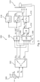
- FIG 3 thus schematically shows a measuring and control structure 300.
- This measuring and control structure 300 begins on the left side shown there with the schematic representation of a vibration sensor 328, which is connected to the vibration sensor 228 of the Figure 2
- This vibration sensor 328 which is designed as an acceleration sensor, can detect two mutually orthogonal vibration directions, which are designated here as X and Y.
- X and Y Preferably and/or in the case of a preferred vibration sensor 228 according to Figure 2 these two directions X and Y lie in a horizontal plane.
- the X direction can indicate a direction of oscillation in the direction of the generator's longitudinal axis and the Y direction a direction perpendicular to it.
- this vibration sensor 328 outputs two measurement signals, one for each of the two directions X and Y. These two vibration signals can be referred to as the longitudinal vibration signal S X and the transverse vibration signal Sv. These two signals are then sent to a separation block 302, in which a separation circuit can be installed, or in which a signal separation described below is carried out by a corresponding microprocessor or a corresponding evaluation program.
- both signals i.e. the longitudinal vibration signal S X and the transverse vibration signal Sv, are each separated into a tower vibration signal and a generator vibration signal.
- the separation block 302 symbolically shows that an overall signal S is separated into a tower signal T and a generator signal G.
- the separation block 302 then outputs three individual signals as a result, namely a tower longitudinal vibration signal S TX , a tower transverse vibration signal S TY , and a generator vibration signal S G .
- this exemplary measurement and control structure 300 proposes to take these three signals into account in a protection control contained in the protection function block 306, namely the tower longitudinal vibration signal S TX , the tower transverse vibration signal S TY , and the generator vibration signal S G .
- an operating control block 308 which contains an operating point control and also receives all information about the vibration, namely the three signals, i.e. the tower longitudinal vibration signal S TX , the tower transverse vibration signal S TY , and the generator vibration signal S G .
- An operating point specified by the operating point control of the operating control block 308 in order to control the wind turbine at this operating point can therefore be adapted, changed or set depending on vibration information, or it can also be determined that a change in the operating point is not necessary.
- the operating control block 308 or the operating point control therein controls the wind turbine, namely at least to the extent that it outputs a target power Ps and a target speed ns.
- These two variables can essentially define the operating point of the wind turbine, which can also be referred to as the operating point. This can be done in particular depending on a detected speed n i and a detected power P i .
- the recorded power P i and then accordingly also the target power Ps, refers in particular to an output power of the wind turbine, which is schematically shown as wind turbine 310.
- the representation of the wind turbine 310 of the Figure 3 is also to be understood only schematically insofar as the measurement and control structure 300 shown can in principle be completely contained in the wind turbine 310.
- this operating point is entered into the main control device 312 by specifying the target speed ns and the target power Ps.
- the main control device 312 is also to be understood only schematically in this respect, because in principle everything that is explained in the measurement and control structure 300 can be carried out in a main control device of a wind turbine. In any case, the main control device 312 can then generate control variables with which the wind turbine 312 or its components are adjusted.
- the main control device 312 of the measurement and control structure 300 of the Figure 3 a torque for each pitch motor, and a target power Ps.
- the torque for the pitch motor is referred to here as M ⁇ . It is specified by the main control device 312 and can relate to various other aspects that are not explained further here, such as taking into account the load of the relevant pitch drives, and taking into account a required adjustment speed, to name just two examples.
- the target power Ps is also only given for illustrative purposes and its implementation can be carried out, for example, in such a way that in the case of a separately excited synchronous generator, a corresponding excitation current for this external excitation is set.
- the setting of the target power Ps can be achieved or influenced by controlling stator currents.
- these two values shown as examples namely the drive torque M ⁇ of a pitch motor and the intended output power Ps are given to the wind turbine 310.
- these values are given to the corresponding control devices.
- the wind turbine 310 is normally operated in this way, i.e. via the operating point control in the operating control block 308 and the further implementation in the main control device 312.
- a protective control as contained in the protective control function block 306, can be activated.
- Such a protective control function monitors the vibrations, namely the tower longitudinal vibration signal S TX , the tower transverse vibration signal S TY , and the generator vibration signal S G .
- the protective control is activated and this initially leads to the normal control being overridden. This is illustrated by the deactivation block 314.
- the protective function block 306 can control the deactivation block 413 and deactivate the normal control according to the operating control block 308 and the main control device 312. This is indicated by the open switch symbolically shown in the deactivation block 314.
- the protection control of the protection function block 306 carries out its own control of the wind turbine 310 in order to bring it to a safe operating point.
- the wind turbine is stopped for this purpose, i.e. controlled to zero speed as quickly as possible.
- it is also necessary to turn the blade angle to the vane position which in Figure 3 than 90 degrees.
- other controls can also be carried out, such as reducing the output power. However, this is not explained further here for the sake of clarity.
- the protection control of the protection function block 306 moves the rotor blades into the feather position and generates a torque for each pitch motor via the main block 316.
- the main block 316 can, for example, generate or specify a torque that initially increases and then decreases again over time for the relevant pitch motor. This is illustrated accordingly in the main block 316.
- this protective control is also designed as a fail-safe control and can have a main control and a secondary control for this purpose.
- the main block 316 can be viewed as the main control for illustrative purposes. or it can be representative of other main control functions that the protective control may have to perform. If this main control or the main block 316 shown as a representative thereof cannot perform the desired control, i.e. the desired generation of the torque for the pitch motor, a secondary block 318 is available as an illustrative element for a secondary control, which then takes over the activity that the main control can no longer perform due to the failure.
- the secondary control and thus illustratively the secondary block 318 can be prepared to carry out the control to be carried out more easily. This is illustrated here by the fact that the secondary block 318 also generates or specifies a torque M ⁇ in order to control a pitch motor, but that this torque specification is carried out less specifically. To illustrate this, the secondary block 318 has a symbolic diagram which is intended to indicate that the torque M ⁇ is simply set to a fixed value here. The rotor blade in question can then rotate to its feather position and this control, i.e. the generation or specification of the torque for the pitch motor, ends when the rotor blade has reached its feather position and actuates a limit switch. This limit switch then means that no further torque is applied to the pitch motor in question.
- the main control and the secondary control can also be designed in the same way and work simultaneously and in parallel, for example by both issuing a torque request to the pitch motors or a pitch motor control in the event of a fault, or only issuing a shutdown signal that the pitch control can execute independently because it is pre-programmed accordingly.
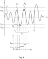
- FIG 4 shows a schematic progression of an oscillation a over time.
- This illustratively shown oscillation a can represent a temporal progression of an acceleration and can be illustrative of a tower oscillation as well as a generator oscillation.
- they can refer to the tower longitudinal oscillation signal S TX , the tower transverse oscillation signal S TY , and the generator oscillation signal S G and show, for example, the respective acceleration.
- These three oscillations can differ in many properties, but in the diagram of the Figure 4 Two possible criteria should be explained in particular which can lead to the detection of a fault. And these criteria are proposed in the same way for the three types of vibration.
- the vibration under consideration can be a tower vibration, both transverse and longitudinal, or a generator vibration.
- the value of the respective criterion or criteria, especially the limit values, can be adjusted accordingly.
- These first two vibration limits can therefore form a first vibration tolerance band. They can each form a first generator vibration limit value or a first tower vibration limit value, or a first tower longitudinal vibration limit value or a first tower transverse vibration limit value.
- the second integration area IF 2 a value that must be integrated is also produced, which is illustrated as the second integration area IF 2. This is also added to the integrated value of the first integration area IF 1. The oscillation then continues and, in the example shown, once again exceeds the first upper oscillation limit value, so that the integration is continued, namely with the contents of the third integration area IF 3 .
- a fault is therefore not detected because in the example shown the oscillation dies down again somewhat and then within the integration period t l no longer falls below the first lower oscillation limit value A u1 and also no longer exceeds the first upper oscillation limit value A o1 , i.e. it remains within the first oscillation tolerance band.
- summing i.e. counting
- the reference integral value i.e. the maximum sum
- the first vibration tolerance band was only exceeded three times, so that the value of the excess sum is 3 and thus no fault has yet been detected.
- the excess integral value or the excess sum can be gradually reduced. For example, if the departure from the first tolerance band is only counted, the excess sum can be reduced by 1 per day.
- a second upper vibration limit value A o2 is provided. This is also marked by a dashed horizontal line and there is also a counterpart, namely the second lower vibration limit value A u2 .
- These two second vibration limit values can thus form a second vibration tolerance band. They can each have a second generator vibration limit value or a second tower vibration limit value, or a second tower longitudinal vibration limit value or a second tower transverse vibration limit value.
Landscapes
- Engineering & Computer Science (AREA)
- Life Sciences & Earth Sciences (AREA)
- Sustainable Development (AREA)
- Sustainable Energy (AREA)
- Chemical & Material Sciences (AREA)
- Combustion & Propulsion (AREA)
- Mechanical Engineering (AREA)
- General Engineering & Computer Science (AREA)
- Health & Medical Sciences (AREA)
- Toxicology (AREA)
- Wind Motors (AREA)
Claims (14)
- Procédé pour faire fonctionner une éolienne sans transmission, laquelle éolienne sans transmission comprend- un générateur, présentant un axe de générateur, destiné à générer une puissance électrique à partir du vent,- une nacelle destinée à supporter le générateur, et- un mât présentant un axe de mât, destiné à supporter la nacelle, et lequel procédé comprend les étapes- de détection d'au moins une oscillation de mât avec une sonde d'oscillations,- de détection d'une oscillation de générateur mécanique déclenchée par au moins une anomalie électrique avec la même sonde d'oscillations, et- de commande de l'éolienne en fonction de l'oscillation de mât détectée et de l'oscillation de générateur détectée, dans lequella sonde d'oscillations- est réalisée en tant que capteur d'accélération, et- détecte une accélération dans au moins deux directions.
- Procédé selon la revendication 1,
caractérisé en ce que
la sonde d'oscillations est disposée- sur le générateur, en particulier sur un stator du générateur,- sur un support de stator supportant le stator du générateur,- dans une partie avant de la nacelle, et/ou- devant l'axe de mât. - Procédé selon la revendication 1 ou 2,
caractérisé en ce que
un signal d'oscillation longitudinale et un signal d'oscillation transversale sont détectés, dans lequel- le signal d'oscillation longitudinale est dirigé dans une direction longitudinale de l'axe de générateur, et- le signal d'oscillation transversale est dirigé dans une direction de manière transversale par rapport à la direction longitudinale, dans lequel en particulier- le signal d'oscillation transversale est détecté également en tant qu'une oscillation dans un plan horizontal. - Procédé selon l'une quelconque des revendications précédentes,
caractérisé en ce que- au moins un signal d'oscillation enregistré par la sonde d'oscillations est divisé en fonction de la fréquence en un signal d'oscillation de mât et en un signal d'oscillation de générateur, dans lequel en particulier- un dispositif de filtration est utilisé, et-- des composantes de fréquence situées en dessous d'une fréquence de coupure pouvant être prédéfinie sont utilisées en tant que signal d'oscillation de mât, et-- des composantes de fréquence situées au-dessus de la fréquence de coupure sont utilisées en tant que signal d'oscillation de générateur. - Procédé selon l'une quelconque des revendications précédentes,
caractérisé en ce que
sont détectées en tant qu'au moins une oscillation de mât- une oscillation longitudinale de mât et- une oscillation transversale de mât. - Procédé selon l'une quelconque des revendications précédentes,
caractérisé en ce que
la commande de l'éolienne est répartie de manière fonctionnelle en- une commande de point de travail destinée à commander l'éolienne dans un point de travail, et- une commande de protection supérieure hiérarchiquement à la commande de point de travail, destinée à surveiller des fonctions de protection de l'éolienne, dans lequel- la commande de protection examine des critères de dysfonctionnement, et-- assure la commande de point de travail en cas d'identification d'un critère de dysfonctionnement prédéfini, et-- se déplace sur un point de travail sécurisé en fonction du critère de dysfonctionnement identifié, en particulier réduit ou arrête une rotation du rotor de l'éolienne. - Procédé selon l'une quelconque des revendications précédentes,
caractérisé en ce que- une ou la commande de protection est réalisée en tant que commande à sûreté intégrée,
et/ou- la commande de protection présente une commande principale et une commande secondaire, dans lequel-- la commande principale exécute la commande de protection, et-- la commande auxiliaire assure la commande de protection ou une partie de celle-ci lorsque la commande principale tombe en panne en totalité ou en partie, ou est exécutée simultanément. - Procédé selon l'une quelconque des revendications précédentes,
caractérisé en ce que- un dysfonctionnement est identifié lorsqu'une des oscillations de mât détectées dépasse une valeur limite d'oscillation de mât prédéfinie, en particulier lorsque-- une oscillation ou l'oscillation longitudinale de mât dépasse une valeur limite d'oscillation longitudinale de mât prédéfinie, et/ou-- une oscillation ou l'oscillation transversale de mât dépasse une valeur limite d'oscillation transversale de mât prédéfinie, et/ou- un dysfonctionnement est détecté lorsque l'oscillation de générateur détectée dépasse une valeur limite d'oscillation de générateur prédéfinie. - Procédé selon l'une quelconque des revendications précédentes,
caractérisé en ce que
pour l'oscillation longitudinale de mât, l'oscillation transversale de mât et/ou l'oscillation de générateur, une courbe d'oscillations est respectivement surveillée, et- il est vérifié pour la courbe d'oscillations si elle quitte une première bande de tolérance d'oscillation, et-- toute sortie de la première bande de tolérance d'oscillation est ajoutée ou intégrée en une somme de dépassement, et-- lorsque la somme de dépassement atteint ou dépasse une somme maximale prédéfinie dans une première période de contrôle prédéfinie,--- l'éolienne est arrêtée en raison d'un dysfonctionnement, ou--- un avertissement d'oscillation est émis et un arrêt de l'éolienne dépend de l'évolution ultérieure de la courbe d'oscillations. - Procédé selon la revendication 9,
caractérisé en ce que- pour arrêter l'éolienne en fonction de l'évolution ultérieure de la courbe d'oscillations-- la somme de dépassement est placée sur zéro dans une première étape ultérieure,-- toute sortie de la première bande de tolérance est à nouveau ajoutée ou intégrée en la somme de dépassement dans une deuxième étape ultérieure jusqu'à ce qu'un avertissement d'oscillation soit à nouveau émis, dans lequel--- alors la première et la deuxième étape ultérieure sont répétées,--- les avertissements d'oscillation survenus dans ce cadre sont comptés et---- il est surveillé si, dans une deuxième période de contrôle, qui est plus longue que la première période de contrôle, le nombre d'avertissements d'oscillation a atteint une limite de nombre d'avertissements prédéfinie et, sur cette base, l'éolienne est arrêtée en raison d'un dysfonctionnement ou elle continue à fonctionner, et/ou que---- il est vérifié si la limite de nombre d'avertissements prédéfinie ou une deuxième limite de nombre d'avertissements est principalement atteinte, tandis que par ailleurs le nombre d'avertissements d'oscillation est réduit respectivement après l'écoulement d'une durée d'un intervalle de réduction d'un numérateur, et, sur cette base, l'éolienne est arrêtée en raison d'un dysfonctionnement ou elle continue à fonctionner. - Procédé selon la revendication 9 ou 10,
caractérisé en ce que
un dysfonctionnement est identifié et l'éolienne est arrêtée lorsque la courbe d'oscillations quitte une fois une deuxième bande de tolérance d'oscillation, qui est supérieure à la première bande de tolérance. - Eolienne sans transmission comprenant- un générateur, présentant un axe de générateur, destiné à produire de la puissance électrique à partir du vent, dans laquelle le générateur peut être entraîné par un rotor aérodynamique avec une ou plusieurs pales de rotor,- une nacelle destinée à supporter le générateur,- un mât destiné à supporter la nacelle,- une sonde d'oscillations destinée à détecter une oscillation de mât, dans laquelle la sonde d'oscillations est également préparée pour détecter une oscillation de générateur mécanique déclenchée par au moins une anomalie électrique, et- un dispositif de commande destiné à commander l'éolienne en fonction de l'oscillation de mât détectée et de l'oscillation de générateur détectée, dans laquellela sonde d'oscillations- est réalisée en tant que capteur d'accélération, et- est préparée pour détecter une accélération dans au moins deux directions.
- Eolienne selon la revendication 12,
caractérisée en ce
qu'un procédé selon l'une quelconque des revendications 1 à 11 est mis en oeuvre, en particulier que le procédé est mis en œuvre sur le dispositif de commande. - Eolienne selon l'une quelconque des revendications 12 ou 13,
caractérisée en ce que
la sonde d'oscillations est disposée- sur le générateur, en particulier sur un stator du générateur,- sur un support de générateur supportant le générateur, et/ou- dans une partie avant de la nacelle.
Applications Claiming Priority (2)
| Application Number | Priority Date | Filing Date | Title |
|---|---|---|---|
| DE102018132413.8A DE102018132413A1 (de) | 2018-12-17 | 2018-12-17 | Verfahren zum Erfassen unterschiedlicher Schwingungen einer Windenergieanlage |
| PCT/EP2019/085331 WO2020127034A1 (fr) | 2018-12-17 | 2019-12-16 | Procédé de détection de vibrations différentes d'une éolienne |
Publications (3)
| Publication Number | Publication Date |
|---|---|
| EP3899253A1 EP3899253A1 (fr) | 2021-10-27 |
| EP3899253B1 true EP3899253B1 (fr) | 2024-06-26 |
| EP3899253C0 EP3899253C0 (fr) | 2024-06-26 |
Family
ID=69005720
Family Applications (1)
| Application Number | Title | Priority Date | Filing Date |
|---|---|---|---|
| EP19827678.4A Active EP3899253B1 (fr) | 2018-12-17 | 2019-12-16 | Procédé de détection de vibrations différentes d'une éolienne |
Country Status (5)
| Country | Link |
|---|---|
| US (1) | US12025101B2 (fr) |
| EP (1) | EP3899253B1 (fr) |
| CN (1) | CN113227567B (fr) |
| DE (1) | DE102018132413A1 (fr) |
| WO (1) | WO2020127034A1 (fr) |
Families Citing this family (7)
| Publication number | Priority date | Publication date | Assignee | Title |
|---|---|---|---|---|
| DK4127747T3 (da) * | 2020-03-24 | 2025-03-31 | Schaeffler Technologies Ag | Fremgangsmåde og anordning til detektering af elektriske strømimpulser, der opstår i et rulleleje som følge af statisk opladning af roterende maskin-/anlægsdele |
| WO2022012739A1 (fr) * | 2020-07-13 | 2022-01-20 | General Electric Renovables España S.L. | Système comprenant une éolienne et procédé de fonctionnement du système |
| EP4008896A1 (fr) * | 2020-12-03 | 2022-06-08 | Siemens Gamesa Renewable Energy A/S | Compensation des cycles de gravité d'un système de tangage |
| CN114687953B (zh) * | 2020-12-31 | 2025-06-06 | 金风科技股份有限公司 | 风力发电机组的振动类型识别方法、控制方法及装置 |
| EP4092263A1 (fr) * | 2021-05-18 | 2022-11-23 | Siemens Gamesa Renewable Energy A/S | Réduction des charges sismiques agissant sur une éolienne |
| EP4257821A1 (fr) * | 2022-04-08 | 2023-10-11 | Siemens Gamesa Renewable Energy A/S | Réduction des charges sismiques agissant sur une éolienne |
| CN118346527B (zh) * | 2024-03-28 | 2026-06-09 | 华能浙江平湖海上风电有限责任公司 | 一种基于振动信号的风机塔筒气动力识别方法 |
Family Cites Families (24)
| Publication number | Priority date | Publication date | Assignee | Title |
|---|---|---|---|---|
| US4410806A (en) | 1981-09-03 | 1983-10-18 | Brulle Robert V | Control system for a vertical axis windmill |
| WO1983001490A1 (fr) | 1981-10-13 | 1983-04-28 | Werner, Per-Axel | Dispositif de securite pour eoliennes |
| US4420692A (en) | 1982-04-02 | 1983-12-13 | United Technologies Corporation | Motion responsive wind turbine tower damping |
| US4703189A (en) | 1985-11-18 | 1987-10-27 | United Technologies Corporation | Torque control for a variable speed wind turbine |
| US5239468A (en) | 1990-12-07 | 1993-08-24 | United Technologies Corporation | Automated helicopter maintenance monitoring |
| US5978972A (en) | 1996-06-14 | 1999-11-09 | Johns Hopkins University | Helmet system including at least three accelerometers and mass memory and method for recording in real-time orthogonal acceleration data of a head |
| DE69901876T2 (de) | 1998-01-14 | 2003-02-20 | Dancontrol Engineering A/S, Hammel | Schwingungsfeststellungs- und steuerungssystem für windturbine |
| DE10016912C1 (de) | 2000-04-05 | 2001-12-13 | Aerodyn Eng Gmbh | Turmeigenfrequenzabhängige Betriebsführung von Offshore-Windenergieanlagen |
| DE10113038C2 (de) | 2001-03-17 | 2003-04-10 | Aloys Wobben | Turmschwingungsüberwachung |
| US7309930B2 (en) * | 2004-09-30 | 2007-12-18 | General Electric Company | Vibration damping system and method for variable speed wind turbines |
| DE102006022266A1 (de) * | 2005-11-04 | 2007-05-10 | Daubner & Stommel GbR Bau-Werk-Planung (vertretungsberechtigter Gesellschafter: Matthias Stommel, 27777 Ganderkesee) | Windenergieanlage |
| JP4814644B2 (ja) * | 2006-02-01 | 2011-11-16 | 富士重工業株式会社 | 風力発電装置 |
| DE102007011835A1 (de) * | 2007-03-12 | 2008-10-02 | µ-SEN GMBH | Sensormodul und Sensornetzwerk zur Überwachung einer Windenergieanlage sowie entsprechende Überwachungsverfahren |
| DE102008023109A1 (de) * | 2007-09-14 | 2009-03-19 | Prüftechnik Dieter Busch AG | Windenergieanlage und Verfahren zum Betreiben einer Windenergieanlage |
| DE202008006322U1 (de) * | 2008-05-08 | 2008-07-17 | Aradex Ag | Windkraftanlage |
| CN102042166B (zh) * | 2010-11-25 | 2012-12-26 | 华锐风电科技(集团)股份有限公司 | 风电机组振动检测装置及方法 |
| DE102010053523B4 (de) * | 2010-12-04 | 2015-09-10 | Nordex Energy Gmbh | Verfahren zur Überwachung einer statischen und/oder dynamischen Stabilität einer Windenergieanlage |
| EP2659242B1 (fr) * | 2010-12-29 | 2023-06-07 | Vestas Wind Systems A/S | Système et methode pour générateur d'éolienne |
| EP2665925B1 (fr) * | 2011-01-20 | 2017-09-13 | Vestas Wind Systems A/S | Procédé pour diagnostique le monitorage d'un système de générateur d'éolienne |
| DE102012218484A1 (de) * | 2012-10-10 | 2014-04-10 | Wobben Properties Gmbh | Verfahren zum Betreiben einer Windenergieanlage |
| DE102014201507A1 (de) * | 2014-01-28 | 2015-07-30 | Wobben Properties Gmbh | Windenergieanlage mit einer Faserwicklung |
| DE102016203013A1 (de) | 2016-02-25 | 2017-08-31 | Innogy Se | Verfahren zur Schwingungszustandsüberwachung einer Windkraftanlage |
| US10774810B2 (en) * | 2016-04-25 | 2020-09-15 | General Electric Company | System and method for estimating high bandwidth tower deflection for wind turbines |
| KR101764540B1 (ko) * | 2016-06-21 | 2017-08-02 | 두산중공업 주식회사 | 풍력발전기 진동 상태감시 및 진단 시스템 |
-
2018
- 2018-12-17 DE DE102018132413.8A patent/DE102018132413A1/de not_active Withdrawn
-
2019
- 2019-12-16 US US17/413,826 patent/US12025101B2/en active Active
- 2019-12-16 CN CN201980083989.8A patent/CN113227567B/zh active Active
- 2019-12-16 WO PCT/EP2019/085331 patent/WO2020127034A1/fr not_active Ceased
- 2019-12-16 EP EP19827678.4A patent/EP3899253B1/fr active Active
Also Published As
| Publication number | Publication date |
|---|---|
| US12025101B2 (en) | 2024-07-02 |
| US20220025862A1 (en) | 2022-01-27 |
| CN113227567A (zh) | 2021-08-06 |
| DE102018132413A1 (de) | 2020-06-18 |
| CN113227567B (zh) | 2024-06-21 |
| EP3899253C0 (fr) | 2024-06-26 |
| WO2020127034A1 (fr) | 2020-06-25 |
| EP3899253A1 (fr) | 2021-10-27 |
Similar Documents
| Publication | Publication Date | Title |
|---|---|---|
| EP3899253A1 (fr) | Procédé de détection de vibrations différentes d'une éolienne | |
| DE10113038C2 (de) | Turmschwingungsüberwachung | |
| DE102007030268B9 (de) | Verfahren und Vorrichtung zur indirekten Bestimmung dynamischer Größen einer Wind- oder Wasserkraftanlage mittels beliebig angeordneter Messsensoren | |
| DE69919910T2 (de) | Methode zur regelung einer windkraftanlage sowie entsprechende windkraftanlage | |
| EP2582972B1 (fr) | Procédé et dispositif empêchant une oscillation transversale d'une éolienne | |
| EP3008334B1 (fr) | Procédé pour injecter une puissance électrique dans un réseau de distribution électrique | |
| WO2009083085A1 (fr) | Procédé permettant de faire fontionner une éolienne | |
| DE102008012957A1 (de) | Verfahren zum Betreiben einer Windenergieanlage und Windenergieanlage | |
| WO2011061015A1 (fr) | Installation éolienne | |
| EP2058513B1 (fr) | Procédé de fonctionnement d'une éolienne | |
| DE102008057934A1 (de) | Windenergieanlage mit einer zentralen Steuerungseinrichtung und einer Steuerungseinheit im Rotor sowie Verfahren zum Betreiben einer derartigen Windenergieanlage | |
| DE102018102224A1 (de) | Verfahren zum Einspeisen elektrischer Leistung in ein elektrisches Versorgungsnetz | |
| DE102007045437A1 (de) | Verfahren zur Steuerung einer Windenergieanlage | |
| DE102007006966A1 (de) | Antriebseinrichtung zum Antreiben von mehreren Achsen | |
| DE112010002632T5 (de) | Verfahren zum Auswuchten einer Windenergieanlage | |
| WO2013072005A1 (fr) | Procédé d'amortissement d'oscillations de torsion dans une installation de production d'énergie | |
| WO2014166824A1 (fr) | Éolienne et procédé de fonctionnement d'une éolienne | |
| EP3124787B1 (fr) | Commande et procede de commande d'eolienne | |
| EP4325046A1 (fr) | Procédé de réglage d'une éolienne | |
| DE102019115943A1 (de) | Verfahren zum Steuern einer Windenergieanlage | |
| EP4253753A1 (fr) | Procédé de détection d'un mauvais réglage d'une pale de rotor d'éolienne | |
| EP4234920B1 (fr) | Réglage individuel des pales dans une éolienne | |
| DE102009051963A1 (de) | Neigungssensor für eine Windkraftanlage | |
| EP4632218A1 (fr) | Procédé de commande d'une éolienne dans un arrêt de sécurité | |
| DE102013007744A1 (de) | Windkraftanlage und Verfahren |
Legal Events
| Date | Code | Title | Description |
|---|---|---|---|
| STAA | Information on the status of an ep patent application or granted ep patent |
Free format text: STATUS: UNKNOWN |
|
| STAA | Information on the status of an ep patent application or granted ep patent |
Free format text: STATUS: THE INTERNATIONAL PUBLICATION HAS BEEN MADE |
|
| PUAI | Public reference made under article 153(3) epc to a published international application that has entered the european phase |
Free format text: ORIGINAL CODE: 0009012 |
|
| STAA | Information on the status of an ep patent application or granted ep patent |
Free format text: STATUS: REQUEST FOR EXAMINATION WAS MADE |
|
| 17P | Request for examination filed |
Effective date: 20210719 |
|
| AK | Designated contracting states |
Kind code of ref document: A1 Designated state(s): AL AT BE BG CH CY CZ DE DK EE ES FI FR GB GR HR HU IE IS IT LI LT LU LV MC MK MT NL NO PL PT RO RS SE SI SK SM TR |
|
| DAV | Request for validation of the european patent (deleted) | ||
| DAX | Request for extension of the european patent (deleted) | ||
| STAA | Information on the status of an ep patent application or granted ep patent |
Free format text: STATUS: EXAMINATION IS IN PROGRESS |
|
| 17Q | First examination report despatched |
Effective date: 20230413 |
|
| GRAP | Despatch of communication of intention to grant a patent |
Free format text: ORIGINAL CODE: EPIDOSNIGR1 |
|
| STAA | Information on the status of an ep patent application or granted ep patent |
Free format text: STATUS: GRANT OF PATENT IS INTENDED |
|
| INTG | Intention to grant announced |
Effective date: 20240119 |
|
| GRAS | Grant fee paid |
Free format text: ORIGINAL CODE: EPIDOSNIGR3 |
|
| GRAA | (expected) grant |
Free format text: ORIGINAL CODE: 0009210 |
|
| STAA | Information on the status of an ep patent application or granted ep patent |
Free format text: STATUS: THE PATENT HAS BEEN GRANTED |
|
| AK | Designated contracting states |
Kind code of ref document: B1 Designated state(s): AL AT BE BG CH CY CZ DE DK EE ES FI FR GB GR HR HU IE IS IT LI LT LU LV MC MK MT NL NO PL PT RO RS SE SI SK SM TR |
|
| REG | Reference to a national code |
Ref country code: GB Ref legal event code: FG4D Free format text: NOT ENGLISH |
|
| REG | Reference to a national code |
Ref country code: CH Ref legal event code: EP |
|
| REG | Reference to a national code |
Ref country code: DE Ref legal event code: R096 Ref document number: 502019011537 Country of ref document: DE |
|
| U01 | Request for unitary effect filed |
Effective date: 20240626 |
|
| U07 | Unitary effect registered |
Designated state(s): AT BE BG DE DK EE FI FR IT LT LU LV MT NL PT SE SI Effective date: 20240701 |
|
| PG25 | Lapsed in a contracting state [announced via postgrant information from national office to epo] |
Ref country code: HR Free format text: LAPSE BECAUSE OF FAILURE TO SUBMIT A TRANSLATION OF THE DESCRIPTION OR TO PAY THE FEE WITHIN THE PRESCRIBED TIME-LIMIT Effective date: 20240626 |
|
| PG25 | Lapsed in a contracting state [announced via postgrant information from national office to epo] |
Ref country code: GR Free format text: LAPSE BECAUSE OF FAILURE TO SUBMIT A TRANSLATION OF THE DESCRIPTION OR TO PAY THE FEE WITHIN THE PRESCRIBED TIME-LIMIT Effective date: 20240927 |
|
| PG25 | Lapsed in a contracting state [announced via postgrant information from national office to epo] |
Ref country code: NO Free format text: LAPSE BECAUSE OF FAILURE TO SUBMIT A TRANSLATION OF THE DESCRIPTION OR TO PAY THE FEE WITHIN THE PRESCRIBED TIME-LIMIT Effective date: 20240926 Ref country code: HR Free format text: LAPSE BECAUSE OF FAILURE TO SUBMIT A TRANSLATION OF THE DESCRIPTION OR TO PAY THE FEE WITHIN THE PRESCRIBED TIME-LIMIT Effective date: 20240626 Ref country code: GR Free format text: LAPSE BECAUSE OF FAILURE TO SUBMIT A TRANSLATION OF THE DESCRIPTION OR TO PAY THE FEE WITHIN THE PRESCRIBED TIME-LIMIT Effective date: 20240927 Ref country code: RS Free format text: LAPSE BECAUSE OF FAILURE TO SUBMIT A TRANSLATION OF THE DESCRIPTION OR TO PAY THE FEE WITHIN THE PRESCRIBED TIME-LIMIT Effective date: 20240926 |
|
| U20 | Renewal fee for the european patent with unitary effect paid |
Year of fee payment: 6 Effective date: 20241118 |
|
| PG25 | Lapsed in a contracting state [announced via postgrant information from national office to epo] |
Ref country code: PL Free format text: LAPSE BECAUSE OF FAILURE TO SUBMIT A TRANSLATION OF THE DESCRIPTION OR TO PAY THE FEE WITHIN THE PRESCRIBED TIME-LIMIT Effective date: 20240626 |
|
| PG25 | Lapsed in a contracting state [announced via postgrant information from national office to epo] |
Ref country code: IS Free format text: LAPSE BECAUSE OF FAILURE TO SUBMIT A TRANSLATION OF THE DESCRIPTION OR TO PAY THE FEE WITHIN THE PRESCRIBED TIME-LIMIT Effective date: 20241026 |
|
| PG25 | Lapsed in a contracting state [announced via postgrant information from national office to epo] |
Ref country code: CZ Free format text: LAPSE BECAUSE OF FAILURE TO SUBMIT A TRANSLATION OF THE DESCRIPTION OR TO PAY THE FEE WITHIN THE PRESCRIBED TIME-LIMIT Effective date: 20240626 |
|
| PG25 | Lapsed in a contracting state [announced via postgrant information from national office to epo] |
Ref country code: RO Free format text: LAPSE BECAUSE OF FAILURE TO SUBMIT A TRANSLATION OF THE DESCRIPTION OR TO PAY THE FEE WITHIN THE PRESCRIBED TIME-LIMIT Effective date: 20240626 Ref country code: SK Free format text: LAPSE BECAUSE OF FAILURE TO SUBMIT A TRANSLATION OF THE DESCRIPTION OR TO PAY THE FEE WITHIN THE PRESCRIBED TIME-LIMIT Effective date: 20240626 |
|
| PG25 | Lapsed in a contracting state [announced via postgrant information from national office to epo] |
Ref country code: SM Free format text: LAPSE BECAUSE OF FAILURE TO SUBMIT A TRANSLATION OF THE DESCRIPTION OR TO PAY THE FEE WITHIN THE PRESCRIBED TIME-LIMIT Effective date: 20240626 Ref country code: ES Free format text: LAPSE BECAUSE OF FAILURE TO SUBMIT A TRANSLATION OF THE DESCRIPTION OR TO PAY THE FEE WITHIN THE PRESCRIBED TIME-LIMIT Effective date: 20240626 |
|
| PG25 | Lapsed in a contracting state [announced via postgrant information from national office to epo] |
Ref country code: SM Free format text: LAPSE BECAUSE OF FAILURE TO SUBMIT A TRANSLATION OF THE DESCRIPTION OR TO PAY THE FEE WITHIN THE PRESCRIBED TIME-LIMIT Effective date: 20240626 Ref country code: SK Free format text: LAPSE BECAUSE OF FAILURE TO SUBMIT A TRANSLATION OF THE DESCRIPTION OR TO PAY THE FEE WITHIN THE PRESCRIBED TIME-LIMIT Effective date: 20240626 Ref country code: RO Free format text: LAPSE BECAUSE OF FAILURE TO SUBMIT A TRANSLATION OF THE DESCRIPTION OR TO PAY THE FEE WITHIN THE PRESCRIBED TIME-LIMIT Effective date: 20240626 Ref country code: PL Free format text: LAPSE BECAUSE OF FAILURE TO SUBMIT A TRANSLATION OF THE DESCRIPTION OR TO PAY THE FEE WITHIN THE PRESCRIBED TIME-LIMIT Effective date: 20240626 Ref country code: IS Free format text: LAPSE BECAUSE OF FAILURE TO SUBMIT A TRANSLATION OF THE DESCRIPTION OR TO PAY THE FEE WITHIN THE PRESCRIBED TIME-LIMIT Effective date: 20241026 Ref country code: ES Free format text: LAPSE BECAUSE OF FAILURE TO SUBMIT A TRANSLATION OF THE DESCRIPTION OR TO PAY THE FEE WITHIN THE PRESCRIBED TIME-LIMIT Effective date: 20240626 Ref country code: CZ Free format text: LAPSE BECAUSE OF FAILURE TO SUBMIT A TRANSLATION OF THE DESCRIPTION OR TO PAY THE FEE WITHIN THE PRESCRIBED TIME-LIMIT Effective date: 20240626 |
|
| PLBE | No opposition filed within time limit |
Free format text: ORIGINAL CODE: 0009261 |
|
| STAA | Information on the status of an ep patent application or granted ep patent |
Free format text: STATUS: NO OPPOSITION FILED WITHIN TIME LIMIT |
|
| 26N | No opposition filed |
Effective date: 20250327 |
|
| PG25 | Lapsed in a contracting state [announced via postgrant information from national office to epo] |
Ref country code: MC Free format text: LAPSE BECAUSE OF FAILURE TO SUBMIT A TRANSLATION OF THE DESCRIPTION OR TO PAY THE FEE WITHIN THE PRESCRIBED TIME-LIMIT Effective date: 20240626 |
|
| REG | Reference to a national code |
Ref country code: CH Ref legal event code: PL |
|
| PG25 | Lapsed in a contracting state [announced via postgrant information from national office to epo] |
Ref country code: CH Free format text: LAPSE BECAUSE OF NON-PAYMENT OF DUE FEES Effective date: 20241231 |
|
| PG25 | Lapsed in a contracting state [announced via postgrant information from national office to epo] |
Ref country code: IE Free format text: LAPSE BECAUSE OF NON-PAYMENT OF DUE FEES Effective date: 20241216 |
|
| U20 | Renewal fee for the european patent with unitary effect paid |
Year of fee payment: 7 Effective date: 20251128 |
|
| PGFP | Annual fee paid to national office [announced via postgrant information from national office to epo] |
Ref country code: GB Payment date: 20251218 Year of fee payment: 7 |
|
| PG25 | Lapsed in a contracting state [announced via postgrant information from national office to epo] |
Ref country code: CY Free format text: LAPSE BECAUSE OF FAILURE TO SUBMIT A TRANSLATION OF THE DESCRIPTION OR TO PAY THE FEE WITHIN THE PRESCRIBED TIME-LIMIT Effective date: 20240626 |
|
| PG25 | Lapsed in a contracting state [announced via postgrant information from national office to epo] |
Ref country code: TR Free format text: LAPSE BECAUSE OF FAILURE TO SUBMIT A TRANSLATION OF THE DESCRIPTION OR TO PAY THE FEE WITHIN THE PRESCRIBED TIME-LIMIT Effective date: 20240626 |
|
| PG25 | Lapsed in a contracting state [announced via postgrant information from national office to epo] |
Ref country code: HU Free format text: LAPSE BECAUSE OF FAILURE TO SUBMIT A TRANSLATION OF THE DESCRIPTION OR TO PAY THE FEE WITHIN THE PRESCRIBED TIME-LIMIT; INVALID AB INITIO Effective date: 20191216 |