EP3899319B1 - Courroie crantée synchrone souple à épissure étroite - Google Patents
Courroie crantée synchrone souple à épissure étroite Download PDFInfo
- Publication number
- EP3899319B1 EP3899319B1 EP19829122.1A EP19829122A EP3899319B1 EP 3899319 B1 EP3899319 B1 EP 3899319B1 EP 19829122 A EP19829122 A EP 19829122A EP 3899319 B1 EP3899319 B1 EP 3899319B1
- Authority
- EP
- European Patent Office
- Prior art keywords
- belt
- tooth
- pair
- clamp
- cords
- Prior art date
- Legal status (The legal status is an assumption and is not a legal conclusion. Google has not performed a legal analysis and makes no representation as to the accuracy of the status listed.)
- Active
Links
Images







Classifications
-
- F—MECHANICAL ENGINEERING; LIGHTING; HEATING; WEAPONS; BLASTING
- F16—ENGINEERING ELEMENTS AND UNITS; GENERAL MEASURES FOR PRODUCING AND MAINTAINING EFFECTIVE FUNCTIONING OF MACHINES OR INSTALLATIONS; THERMAL INSULATION IN GENERAL
- F16G—BELTS, CABLES, OR ROPES, PREDOMINANTLY USED FOR DRIVING PURPOSES; CHAINS; FITTINGS PREDOMINANTLY USED THEREFOR
- F16G1/00—Driving-belts
- F16G1/28—Driving-belts with a contact surface of special shape, e.g. toothed
-
- A—HUMAN NECESSITIES
- A01—AGRICULTURE; FORESTRY; ANIMAL HUSBANDRY; HUNTING; TRAPPING; FISHING
- A01D—HARVESTING; MOWING
- A01D61/00—Elevators or conveyors for binders or combines
- A01D61/002—Elevators or conveyors for binders or combines transversal conveying devices
-
- A—HUMAN NECESSITIES
- A01—AGRICULTURE; FORESTRY; ANIMAL HUSBANDRY; HUNTING; TRAPPING; FISHING
- A01D—HARVESTING; MOWING
- A01D57/00—Delivering mechanisms for harvesters or mowers
- A01D57/20—Delivering mechanisms for harvesters or mowers with conveyor belts
-
- A—HUMAN NECESSITIES
- A01—AGRICULTURE; FORESTRY; ANIMAL HUSBANDRY; HUNTING; TRAPPING; FISHING
- A01D—HARVESTING; MOWING
- A01D61/00—Elevators or conveyors for binders or combines
- A01D61/02—Endless belts
-
- B—PERFORMING OPERATIONS; TRANSPORTING
- B65—CONVEYING; PACKING; STORING; HANDLING THIN OR FILAMENTARY MATERIAL
- B65G—TRANSPORT OR STORAGE DEVICES, e.g. CONVEYORS FOR LOADING OR TIPPING, SHOP CONVEYOR SYSTEMS OR PNEUMATIC TUBE CONVEYORS
- B65G15/00—Conveyors having endless load-conveying surfaces, i.e. belts and like continuous members, to which tractive effort is transmitted by means other than endless driving elements of similar configuration
- B65G15/30—Belts or like endless load-carriers
- B65G15/32—Belts or like endless load-carriers made of rubber or plastics
- B65G15/34—Belts or like endless load-carriers made of rubber or plastics with reinforcing layers, e.g. of fabric
- B65G15/36—Belts or like endless load-carriers made of rubber or plastics with reinforcing layers, e.g. of fabric the layers incorporating ropes, chains, or rolled steel sections
-
- B—PERFORMING OPERATIONS; TRANSPORTING
- B65—CONVEYING; PACKING; STORING; HANDLING THIN OR FILAMENTARY MATERIAL
- B65G—TRANSPORT OR STORAGE DEVICES, e.g. CONVEYORS FOR LOADING OR TIPPING, SHOP CONVEYOR SYSTEMS OR PNEUMATIC TUBE CONVEYORS
- B65G15/00—Conveyors having endless load-conveying surfaces, i.e. belts and like continuous members, to which tractive effort is transmitted by means other than endless driving elements of similar configuration
- B65G15/30—Belts or like endless load-carriers
- B65G15/32—Belts or like endless load-carriers made of rubber or plastics
- B65G15/42—Belts or like endless load-carriers made of rubber or plastics having ribs, ridges, or other surface projections
-
- B—PERFORMING OPERATIONS; TRANSPORTING
- B65—CONVEYING; PACKING; STORING; HANDLING THIN OR FILAMENTARY MATERIAL
- B65G—TRANSPORT OR STORAGE DEVICES, e.g. CONVEYORS FOR LOADING OR TIPPING, SHOP CONVEYOR SYSTEMS OR PNEUMATIC TUBE CONVEYORS
- B65G23/00—Driving gear for endless conveyors; Belt- or chain-tensioning arrangements
- B65G23/02—Belt- or chain-engaging elements
- B65G23/04—Drums, rollers, or wheels
- B65G23/06—Drums, rollers, or wheels with projections engaging abutments on belts or chains, e.g. sprocket wheels
-
- F—MECHANICAL ENGINEERING; LIGHTING; HEATING; WEAPONS; BLASTING
- F16—ENGINEERING ELEMENTS AND UNITS; GENERAL MEASURES FOR PRODUCING AND MAINTAINING EFFECTIVE FUNCTIONING OF MACHINES OR INSTALLATIONS; THERMAL INSULATION IN GENERAL
- F16G—BELTS, CABLES, OR ROPES, PREDOMINANTLY USED FOR DRIVING PURPOSES; CHAINS; FITTINGS PREDOMINANTLY USED THEREFOR
- F16G3/00—Belt fastenings, e.g. for conveyor belts
- F16G3/06—Belt fastenings, e.g. for conveyor belts with outwardly-bent, mutually-connected belt ends
-
- A—HUMAN NECESSITIES
- A01—AGRICULTURE; FORESTRY; ANIMAL HUSBANDRY; HUNTING; TRAPPING; FISHING
- A01D—HARVESTING; MOWING
- A01D61/00—Elevators or conveyors for binders or combines
- A01D61/04—Chains
-
- B—PERFORMING OPERATIONS; TRANSPORTING
- B65—CONVEYING; PACKING; STORING; HANDLING THIN OR FILAMENTARY MATERIAL
- B65G—TRANSPORT OR STORAGE DEVICES, e.g. CONVEYORS FOR LOADING OR TIPPING, SHOP CONVEYOR SYSTEMS OR PNEUMATIC TUBE CONVEYORS
- B65G2201/00—Indexing codes relating to handling devices, e.g. conveyors, characterised by the type of product or load being conveyed or handled
- B65G2201/02—Articles
- B65G2201/0202—Agricultural and processed food products
-
- B—PERFORMING OPERATIONS; TRANSPORTING
- B65—CONVEYING; PACKING; STORING; HANDLING THIN OR FILAMENTARY MATERIAL
- B65G—TRANSPORT OR STORAGE DEVICES, e.g. CONVEYORS FOR LOADING OR TIPPING, SHOP CONVEYOR SYSTEMS OR PNEUMATIC TUBE CONVEYORS
- B65G2201/00—Indexing codes relating to handling devices, e.g. conveyors, characterised by the type of product or load being conveyed or handled
- B65G2201/04—Bulk
-
- B—PERFORMING OPERATIONS; TRANSPORTING
- B65—CONVEYING; PACKING; STORING; HANDLING THIN OR FILAMENTARY MATERIAL
- B65G—TRANSPORT OR STORAGE DEVICES, e.g. CONVEYORS FOR LOADING OR TIPPING, SHOP CONVEYOR SYSTEMS OR PNEUMATIC TUBE CONVEYORS
- B65G2812/00—Indexing codes relating to the kind or type of conveyors
- B65G2812/02—Belt or chain conveyors
- B65G2812/02128—Belt conveyors
- B65G2812/02217—Belt conveyors characterised by the configuration
Definitions
- the field to which the disclosure generally relates is a belt comprising a cover layer and opposing continuous tooth section defining an outer surface, a cross-linked elastomeric body and a tensile reinforcement section disposed between the cover layer and the cross-linked elastomeric body, wherein the continuous tooth section is comprised of a plurality of tooth structures, wherein each tooth of the plurality of tooth structures comprises a tooth flank, a land, and an easement area between the tooth flank and the land, wherein the easement area has a progressively decreasing radial thickness from the tooth flank to the land, wherein the belt is a spliced belt having a splice positioned in one tooth structure between a pair of corresponding lands. Toothed belts are useful for harvesting machines, and more particularly to toothed belts used in feederhousings.
- Agricultural harvesting machines such as combine harvesters are used to reap, thresh, and winnow grain crops such as wheat, rye, barley, corn, soybeans, oats, flax, sunflower, canola, and the like. More specifically, combine harvesters are used to cut grain crops at the base, separate the grains from the remainder of the plant (the chaff), and sort the grain from the chaff.
- combine harvesters require special adaptations to accommodate specific crops, navigate through field landscapes, and resist damage from the crops, stone, and the elements; especially moisture and high temperature which can lead to the degradation of the machine's rubber components.
- combine harvesting machines gather crops using a header as the machine moves through a field.
- the header may be one of several types, each of which provides a means of gathering a particular type of crop.
- the header is connected to a feederhousing which provides a means of conveying the crop to a threshing mechanism which is part of the harvesting machine.
- headers In one type of header which is useful for small grain, the gathered crops are pushed by a reel into a cutter bar, which runs the length of the header and is equipped with teeth made of metal or plastic to cut crops at their base. Headers may have a rigid or flexible header platform depending upon the operator's needs. Flexible header platforms, or "flex headers" have a cutter bar which is capable of flexing over uneven terrain. Machines using flex headers are most often used to cut soybeans, whereas conventional header platforms have a rigid cutter bar and are most often used to cut cereal crops. Freshly cut crops fall behind the cutter bar and onto a plurality of draper belts which are wrapped around parallel spaced rollers.
- Draper belts function primarily to consolidate crops and move the crops within the header towards a feederhousing, which then conveys the crops to a threshing mechanism.
- the freshly cut crop may be conveyed within the header to the feederhousing by augers.
- a second type of header is useful for row crops such as corn.
- This type of header has dividers which define crop gathering gaps for each crop row. In each gap, the ears of corn containing the corn grain kernels is removed from the corn stock and is conveyed by auger or belt to the feederhousing. The stalk and other plant residue are separated from the ears and remain in the field so that the amount of material processed by the threshing mechanism is minimized.
- a third type of header is useful for crops which have been previously cut and collected for drying or other aging in the field.
- This type of header includes a pickup apron to convey the cut crop into the header and onto a plurality of draper belts which are wrapped around parallel spaced rollers.
- the draper belts function primarily to consolidate crops and to gently move the crops within the header towards a feederhousing, which then conveys the crops to the threshing mechanism.
- the feederhousing movably supports the header and connects it to the threshing mechanism contained in the main body of the combine harvester.
- the feederhousing includes a closed channel, typically of rectangular cross section, having an inlet opening at the forward end which engages the header at the point where the header discharges the crop.
- the feederhousing has a discharge opening at the rearward end which engages the desired inlet area of the threshing mechanism.
- the crop is conveyed within the closed channel of the feederhousing from the header to the threshing mechanism by bars or cleats which are attached to chains or belts.
- the chains or belts are supported by a shaft and sprockets near the discharge opening, and by one or more shafts or drums near the inlet opening. Rotation of the belts or chains about the shafts moves the bars or cleats in a closed loop path from the inlet to the discharge.
- the moving bars or cleats carry or drag the crop from the header to the threshing mechanism
- Additional mechanisms within the feederhousing may be used to assist the conveyance of the crop. They may guide the path of the bars or cleats or chains, allow limited motion of the drums, and/or control the tension of the chain.
- the bars and belts or chains are subject to abrasive wear from contact with the crop, and to damage from foreign object that inadvertently enter the feederhousing. Belts made in a continuous loop are difficult to install in a traditional feederhousing, so an assembly of belts and bars in which the continuous loop can be opened for installation is useful.
- the grain is separated from the plant stems, cobs, straw, leaves, and chaff.
- the threshed grains are collected in a grain collecting tank, and the plant waste, or chaff, is moved to discharge openings of the threshing mechanism for disposal to the field or for collection if desired as a secondary product.
- the header of this machine usually is made to engage with row crops, but instead of striping ears from the stalk, the stalk is cut near the ground and the entire plant is conveyed to the feederhousing.
- the feederhousing conveys the plant to a chopping mechanism instead of a threshing mechanism to produce animal feed.
- US 5 405 299 A shows a timing belt comprising a tensile cords embedded in an elastic body.
- the timing belt comprises a plurality of tooth structures wherein each tooth of the plurality of tooth structures comprises a tooth flank a land and an easement area between the tooth flank and the land, wherein the easement area has a progressively decreasing radial thickness from the tooth flank to the land.
- EP 3 409 098 A1 relates to a coupler for endless belts of conveyors for example for agricultural harvesters.
- the belt has a first hole at the first end and a second hole at the second end.
- the coupler comprises a first pin extending through the first hole and a second pin extending through the second hole when the belt ends are coupled by the coupler.
- EP 3 078 880 A1 relates to a belt as an endless traction means for conveyor belts of agricultural machines. At least one fabric layer of each belt end is folded back onto itself and wraps around a thickening and runs between the thickening and a stop forming an abutment for the thickening, that it gets jammed between the thickening and the stop when tension acts on the belt in the return direction.
- DE 20 2005 020 662 U1 relates to a connecting unit connecting two ends of a timing belt.
- the connecting unit comprises an outer body and a clamping unit arranged inside the body.
- the clamping unit comprises an adjusting mechanism, that extends the clamping unit outwardly in a direction of a wall of the body. The belt ends are clamped between the clamping unit and the body.
- the splice comprises a pair of looped cords extending from ends of the tensile reinforcement section, a pair of glad hand connectors disposed between the pair of looped cords, a clamp disposed over the pair of glad hand connectors and the pair of looped cords on a side of the belt comprising the cover layer, and a bottom clamp disposed on an end of the one tooth, wherein a clamp connector extends through the clamp and between the pair of glad hand connectors, and wherein the clamp connector securely engages the bottom clamp.
- Some embodiments of the disclosure are directed to belts having a cover layer and opposing continuous tooth section defining an outer surface, a cross-linked elastomeric body, and a tensile reinforcement section disposed between the cover layer and the cross-linked elastomeric body.
- the continuous tooth section includes a plurality of tooth structures, each having tooth flank, a land, and an easement area between the tooth flank and the land, and the easement area has a progressively decreasing radial thickness from the tooth flank to the land.
- the easement area reduces shear stress between the tensile reinforcement and the elastomeric body of the tooth.
- the easement area provides a gradual change in belt bending stiffness from a high bending stiffness near the tooth flank to a low bending stiffness near the land. In some aspects, the easement area controls the bending radius of the tensile layer between the tooth flank and the land as the belt engages a sprocket.
- the easement area near the land has a low angle of contact with the outer portion of a sprocket tooth when engaging a sprocket, and the low angle of contact may provide a radial or circumferential displacement of the belt with respect to the sprocket when forces applied to the belt tooth flank by the sprocket tooth are excessive, and the displacement of the belt can transfer a portion of those forces to other belt tooth structures of the continuous tooth section, thus limiting the force applied to an individual tooth.
- the belt is an endless belt, while in some other aspects, the belt is a spliced belt having a splice.
- the belts are spliced belts
- the belt is first made in an open loop containing a desired number of whole teeth along the loop, and with a partial tooth at each end of the loop.
- a splice is positioned in one tooth structure between a pair of corresponding lands.
- the splice includes such elements as a pair of looped cords extending from ends of the tensile reinforcement section, a pair of connectors disposed between the pair of looped cords, a clamp disposed over the pair of connectors and the pair of looped cords on a side of the belt comprising the cover layer, and/or a bottom clamp disposed on an end of the one tooth, where a clamp connector extends through the clamp and between the pair of glad hand connectors, and where the clamp connector securely engages the bottom clamp.
- a deadman may be disposed within each loop of the pair of looped cords, and in some cases, the deadman have a kickstand structure.
- Some other embodiments of the disclosure are spliced belts having a cover layer and opposing continuous tooth section defining an outer surface, where the continuous tooth section has a plurality of tooth structures, and where each tooth of the plurality of tooth structures has a tooth flank, a land, and an easement area between the tooth flank and the land.
- the belt also includes a cross-linked elastomeric body, a tensile reinforcement section disposed between the cover layer and the cross-linked elastomeric body, and a splice positioned in one tooth structure between a pair of corresponding lands.
- the splice has a pair of looped cords extending from ends of the tensile reinforcement section, a pair of glad hand connectors disposed between the pair of looped cords, a clamp disposed over the pair and the pair of looped cords on a side of the belt having the cover layer, and a bottom clamp disposed on an end of the one tooth.
- the clamp connector extends through the clamp and between the pair of glad hand connectors, and the clamp connector securely engages the bottom clamp.
- a deadman is disposed within each loop comprised in the pair of looped cords, and the deadman may have a kickstand structure.
- the easement area has a progressively decreasing radial thickness from the tooth flank to the land, and the easement area may have a low angle of contact with a sprocket at the land end.
- each belt comprised in the plurality of elastomeric drive belts includes a cover layer and opposing continuous tooth section defining an outer surface, a cross-linked elastomeric body, and a tensile reinforcement section disposed between the cover layer and the cross-linked elastomeric body.
- the continuous tooth section includes a plurality of tooth structures, each having a tooth flank, a land, and an easement area between the tooth flank and the land.
- the easement area has a progressively decreasing radial thickness from the tooth flank to the land, and may have a low pressure-angle of contact with a sprocket.
- the belt is an endless belt, while in some other aspects, the belt is a spliced belt having a splice.
- each of the spliced belts further include a splice positioned in one tooth structure between a pair of corresponding lands.
- the splice has a pair of looped cords extending from ends of the tensile reinforcement section, a pair of glad hand connectors disposed between the pair of looped cords, a clamp disposed over the pair and the pair of looped cords on a side of the belt having the cover layer, and/or a bottom clamp disposed on an end of the one tooth.
- a clamp connector extends through the clamp and between the pair of glad hand connectors, and the clamp connector securely engages the bottom clamp.
- a deadman in disposed within each loop of the pair of looped cords, and the deadman may have a kickstand structure.
- a range of from 1 to 10 is to be read as indicating each and every possible number along the continuum between about 1 and about 10.
- any references to "one embodiment” or “an embodiment” means that a particular element, feature, structure, or characteristic described in connection with the embodiment is included in at least one embodiment.
- the appearances of the phrase “in one embodiment” in various places in the specification are not necessarily referring to the same embodiment.
- belts according to the disclosure include a cover layer and opposing continuous tooth section defining an outer surface as depicted in FIG. 1 , which illustrates a portion of a belt in a fragmented perspective view according to one embodiment of the disclosure.
- the belts are HNBR (hydrogenated nitrile butadiene rubber) belts where the back side of the HNBR belt is a cover 102 to protect the tensile cords.
- the cover can be elastomer HNBR or fabric impregnated with elastomer.
- the tensile cords 114 are embedded in a cord support elastomer 108 which may be the same elastomer as used in the cover 102 or the body 106.
- the body 106 is commonly called the tooth stock elastomer and may not be continuous along the length of the belt.
- the toothed surface of the belt 104 is usually covered with one or more layers of continuous fabric that follow the contour of the tooth and the land between the teeth.
- the outer surface of the outer fabric layer 112 may be impregnated with an elastomer with low coefficient of friction and with resistance to abrasion as described in US Pat. No. 8,192,797 B2 .
- the inner surface of the inner layer of fabric may be impregnated with elastomer compatible with the body 106 or the cord encapsulant 108.
- the surfaces between the layers may be impregnated with the material of 104, 106, or 108.
- the tensile cords 114 may be placed close to the inner fabric layer in the land area between the belt teeth and define the neutral plane of the belt in bending.
- the cross-linked elastomeric body 106 is based upon a urethane material, formed from the reaction product of a polyisocyanate and a hydroxyl functional polyol which react during a molding process used in forming belt 100.
- the polyisocyanate and the hydroxyl functional polyol may be injected separately into the belt mold and reacted during the belt molding process. Further, the polyisocyanate and the hydroxyl functional polyol may envelop the fabric reinforcement prior to reacting during the belt molding process; or in some cases during reacting in the belt molding process.
- the belt mold Prior to injection, the belt mold typically contains the outer tension section 102, the tensile reinforcement section 108 and the fabric reinforcement 110 prior to injecting the polyisocyanate and the hydroxyl functional polyol.
- any suitable material for the cross-linked elastomeric materials can be used.
- suitable elastomeric materials include chloroprene rubber (“CR”), acrylonitrile butadiene rubber (“NBR”), styrene-butadiene rubber (“SBR”), alkylated chlorosulfonated polyethylene (“ACSM”), epichlorohydrin, butadiene rubber (“BR”), natural rubber (“NR”) and ethylene alpha olefin elastomers such as ethylene propylene terpolymer (“EPDM”) and ethylene propylene copolymer (“EPM”), or a combination of any two or more of the foregoing.
- CR chloroprene rubber
- NBR acrylonitrile butadiene rubber
- SBR styrene-butadiene rubber
- ACSM alkylated chlorosulfonated polyethylene
- BR butadiene rubber
- NR natural rubber
- the materials forming the elastomeric body 106 and cover layer 102 may be blended with conventional compounding ingredients including fillers, plasticizers, carbon black, agents to reduce static build up, stabilizers, vulcanization agents/curatives and accelerators, in amounts conventionally employed.
- the tensile reinforcement section 108 disposed between the outer tension section and the cross-linked elastomeric body is useful for providing support and strength to belts.
- the tensile reinforcement section 108 contains a plurality of cords 114 aligned longitudinally along the length of main body portion.
- any type of tensile reinforcement section known to the art may be utilized.
- any desired material may be used as the tensile members in the tensile reinforcement section, such as cotton, rayon, nylon, polyester, aramid, steel, carbon fiber, PBO, and even discontinuous fibers oriented for low load carrying capability.
- the cords are embedded in a material, the embedding material being an elastomeric material.
- continuous tooth section 104 has a plurality of tooth structures.
- Each tooth 116 of the plurality of tooth structures includes tooth flanks 118, lands 120, and easement areas 122 between the tooth flanks 118 and the lands 120, which is illustrated in FIG. 2 .
- the easement areas 122 have a progressively decreasing radial thickness from the tooth flanks 118 to the lands 120.
- the easement area 122 of the tooth profile may serve to support the plurality of cords 114 on a curve, as well as improves fatigue life of plurality of cords 114 by preventing small bend radiuses in the plurality of cords 114, as belt 100 engages and bends around a sprocket.
- the tensile cords 114 are straight in the area above the tooth, the easements and the land between teeth when the belt is under tension between sprockets or other supports.
- the tensile cords 114 above the tooth may be straight or curved when the belt under tension is bent around a sprocket, depending on the bending stiffness of the belt in the area of the tooth.
- the tensile cords 114 above the land 120 may be bent to the radius of the top of the sprocket tooth, in an arc with total angle equal to the angle between adjacent belt teeth.
- the arc radius is much less than the outer radius of the sprocket teeth, and fatigue damage to the cord 114 is increased in the land area 120.
- the cord 114 is supported at a gently decreasing radius from the tooth flank to the land, and the arc length at the land is reduced to near zero, resulting in reduced fatigue of the cord 114.
- the support of the cord 114 in the easement area 122 is partially due to the variable bending stiffness of the belt 100 in the easement area 122, which also supports the cord 114 if the belt is bent around a flat drum instead of a sprocket.
- the support of the cord 114 in the easement area 122 is also due to decreasing radial thickness of the easement 122 from the tooth flank to the land which conforms to the flanks 118 of the sprocket tooth as the belt 100 is bent.
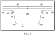
- FIG. 3 which illustrates in a portion of conventional toothed belt in rack form (the neutral plane is a straight line).
- FIG. 3 shows one belt tooth 302, top surface 304 of the belt and a portion of the belt lands 306, 308 between the teeth on either side of the tooth 302.
- Line 310 is the neutral plane of the belt which would be near the center of tensile cords.
- the trapezoidal tooth 302 defines bottom 312.
- the tooth 302 also defines flanks 314, 316 of the trapezoidal tooth, which are joined to the lands 306, 308 and tooth bottom 312 with fillet curves 318, 320, 322, 324.
- the belt has a tooth pitch of 50mm, neutral plane 310 to lands 306, 308 of 1.7mm, and neutral plane 310 to top surface 304 of 1.5mm.
- FIG. 4 depicts a section of the trapezoidal toothed belt shown in FIG. 3 , when wrapped around a sprocket in an ideal form.
- Two cylindrical teeth 402, 404 on sprocket 406 are shown.
- the angled lines 408, 410 passing through the two cylindrical teeth 402, 404 represent one pitch of sprocket 406 and meet on the center 412 of sprocket 406.
- the belt also defines top surface 304 and neutral plane 310 which is near the center of tensile cords.
- the belt tooth 302 and lands 306, 308 are deformed into an idealized shape where the lands are in contact with the outer diameter of sprocket 406, and the lands 306, 308 as well as belt tooth 302 are curved so that the belt neutral plane 310 is an arc with constant radius centered at the center 412 of the sprocket 406.
- the bending radius of cords is the sprocket outside radius plus the belt neutral plane to land distance. This the condition which provides the largest possible cord bend radius for the given sprocket size (pitch and number of teeth).
- the belt tooth pitch is 50mm
- neutral plane to land is 1.7mm
- neutral plane to top is 1.5mm
- sprocket pitch is 50mm
- number of teeth is 10
- the tooth-to-tooth angle is 36°, having half angle of 18°
- sprocket pin outer diameter is 20mm
- cord bend radius is 79.577mm
- pitch line arc length is 50mm.
- FIG. 5 which illustrates a section of the trapezoidal toothed belt, such as that shown in FIG. 3 , when wrapped around a sprocket 506 in a form that has an undesirably small cord bending radius, and where the belt land wraps around the cylindrical teeth 502, 504 of the sprocket 506, at regions 520, 522.
- the belt cords positioned about belt neutral plane 510, are under tension, which pulls the unsupported belt tooth 512 and parts of the lands 514, 516 into a chordal straight-line X.
- the tension also holds part of the lands at regions 524, 526 in an arc around the outer diameter of the cylindrical sprocket teeth 502, 504.
- the minimum bending radius of the cord is the radius of the sprocket pin plus the belt PLD neutral plane to land, which is significantly smaller than that depicted in FIG. 4 , and, for example, in comparison, has a cord bend radius of 11.7mm at arc of 36° with a ten tooth sprocket.
- FIG. 6 depicts a section of a toothed belt according to the disclosure, when wrapped around pins of a sprocket.
- toothed belt 600 includes easements 606, 608 wrapped around pins 602, 604 of sprocket 610.
- the easements 606, 608 are a transition area between the belt tooth flank 612, 614 and the land 616, 618, which significantly shorten the length of the land, between teeth, in comparison to that shown FIG. 5 .
- Such easements 606, 608 prevent the undesirably small cord bending radius of FIG. 5 where the land 514, 516 wraps around the sprocket tooth pin 502, 504.
- the belt cords positioned about belt neutral plane 620, are under tension and the bending stiffness of the belt 600 in the tooth 622 area may hold the cord above the tooth 622 in a straight chordal line or in a slight curve with a significantly larger cord bending radius than that depicted in FIG. 5 .
- the bottom 624 of the tooth 622 is unsupported.
- easement 606 or 608 can be defined as a belt structure as having a progressively decreasing radial thickness, relative sprocket 610 center point 626, between tooth flank 612, 614 and land 616, 618 respectively. This is contrast to that depicted in FIG.
- the radius of the belt at easement 606 or 608 are like or similar to the radius of the sprocket pin 602 or 604.
- Each easement area 606, 608 acts as a tapered cantilever beam to support the cord at a variable radius, until the easement 606, 608 deforms to contact the sprocket pin 602, 604.
- the cord bending radius is determined by the radial thickness of the deformed easement 606, 608 at each point between the tooth flank 612, 614 and the small remaining land 616, 618.
- the narrow land is in contact with the sprocket at the outer diameter of the sprocket pin, but the arc of contact is very small and the curve of the cord over the easement brings the cord tangent to the cord at the end of the easement of the next tooth.
- the minimum bend radius of the cord is much greater than the minimum radius shown in FIG. 5 .
- belts according to the disclosure having easement area designs which reduce the peak shear stress and increased tooth fatigue life due to larger shear area, may be useful in an endless belt where the drive shaft(s)/sprockets are removeable from the equipment in which the belt is used.
- the belts according to the disclosure are spliced belts which are installed in equipment without removal of drive shaft(s)/sprockets.
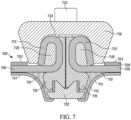
- spliced belt 700 includes a first end 702 and opposing second end 704.
- a tensile reinforcement section includes a plurality of cords 706, disposed between a cover layer 708 and a cross-linked elastomeric body 710.
- Cords 706 extend from both first end 702 and opposing second end 704.
- the extended portion of the pair of cords 706 are each looped to form looped cords 712, which are positioned in a tooth structure of spliced belt 700, between a pair of corresponding lands 714.
- An optional fabric layer 715 may be disposed on the outer surface of the tooth structure, or slightly inward therefrom.
- a pair of glad hand connectors 716 are disposed between the pair of looped cords 712, and a clamp 718 disposed over the pair of looped cords 712 on a side of the belt 700 where the cover layer 708 is located.
- a bottom clamp 720 is disposed on an end of the tooth structure, and a clamp connector 722 extends through the clamp 718 and between the pair of glad hand connectors 716, and the clamp connector 722 securely engages the bottom clamp 720.
- an air space compression zone 724 may remain outwardly from looped cords 712.
- a deadman 726 is disposed within looped cords 712.
- Ends 702 and 704 are two ends of the same belt, and each end contains one half of the tooth, including one deadman 726, and one septum (716).
- FIG. 7 shows slightly more than one pitch and includes only the two half-tooth ends with the septums in contact, along with the top 718, bottom clamp 720 and connector 722.
- Bottom clamp 720 interferes with the tooth fabric and rubber in this assembled view.
- the looped cords are shown as turned in a 270 degree loop, which, as tension in the cords 706 increases, the loops provide a self-activating increase in the clamping force on the end of the cord loop between the deadman 726 and upper clamp 718.
- the loops could be turned in any suitable amount, such as, but not necessarily limited to, 45 degrees, 90 degrees, 180 degrees, or even 360 degrees.
- spliced belt 800 includes a first end 802 and opposing second end 804. Similar to above, tensile reinforcement section includes a plurality of cords 806, disposed between a cover layer 808 and a cross-linked elastomeric body 810 where cords 806 extend from both first end 802 and opposing second end 804. The extended portion of cords 806 are each looped to form looped cords 812, positioned in a tooth structure of spliced belt 800, between a pair of corresponding lands 814.
- An optional fabric layer 815 may be disposed on the outer surface of the tooth structure, or slightly inward therefrom.
- a pair of glad hand connectors 816 are disposed between the pair of looped cords 812, and a clamp 818 disposed over the pair of looped cords 812.
- a bottom clamp 820 is disposed on an end of the tooth structure, and a clamp connector 822 extends through the clamp 818 and between the pair of glad hand connectors 816, and the clamp connector 822 securely engages the bottom clamp 820, while an air space compression zone 824 remains outwardly from looped cords 812.
- a deadman 826 is disposed within looped cords 812.
- Deadman 826 includes a kickstand 828.
- the kick stands 828, glad hands 816 and mold used to form the belt end confine the deadman 826 and displace rubber encapsulating the cord 826 to create pinch points and glands.
- the first pinch point 830 is just above the 90-degree cord bend from horizontal to vertical, and the first gland 832 is above the first pinch point 830.
- a second pinch point 834 is in the 180-degree bend at the top.
- the cut end of the cord ends at the top of the kickstand 828 in the second gland 836. With 270 degrees of wrap, increasing the tension in the cords causes the deadman 826 to rotate when the cord and elastomer in the gland area 832 deforms.
- the kickstand 828 limits the rotation movement of the deadman 826 so that it is not separated from the septum 816 and overall pitch of the spliced tooth is accurately maintained.
- spliced belt 900 includes almost all of the same elements as shown in FIG. 8 for spliced belt 800. However, ends of the cords are extended to be pinched between the deadman kickstand and the clamp. As depicted, the extended ends 902 from cord loops 812, of cord 806, is disposed between deadman 826 kickstands 828 and the clamp 818, or otherwise extended over the tip of the kickstands 828 to clamp the ends of cord 806. Initial clamping force is provided by top clamp 818 when securely connected to bottom clamp 820 via the clamp connector.
- the glad-hands shown on the above figures are formed of a pair of septums which are essentially symmetric with an interlocking feature.
- the septums can be brought in contact from the left and right with vertical and horizontal alignment controlled by glad-hand pins and sockets, after which the top and bottom clamp can be applied.
- spliced belt 1000 includes many of the same elements as described in the embodiments above including a first end 1002 and opposing second end 1004, a plurality of cords 1006, where extended portion of cords 1006 are each looped to form looped cords 1012, and a clamp 1018 disposed over the pair of looped cords 1012.
- asymmetrical septum connectors 1040 and 1042 are disposed between the pair of looped cords 1012, and beneath clamp 1018 disposed over the pair of looped cords 1012.
- Deadmans 1026 with kickstands 1028 are disposed within looped cords 1012.
- the bottom clamp mechanism is incorporated into septum connector 1040 and clamp connector 1022, as a part of septum connector 1040, extends up between and between asymmetrical connectors 1040, 1042, and through clamp 1018, and is secured to clamp 1018 with a fastener.
- Asymmetrical septum connectors 1040 and 1042 may have corresponding mating interlocking features 1044 and 1046.
- septums 1040 and 1042 in FIG. 10 are not a glad-hand design (i.e. symmetrical septums). Also, here a bottom clamp is incorporated in septum 1040, and the septums 1040 and 1042 cannot be brought in contact from the left and right unless septum 1040 is lower than septum 1042 so that the interlocking features 1044 and 1046 do not interfere. After the septum faces touch, the septum 1040 must be slid upward to the same height as 1042. The vertical alignment is dependent on the engagement of interlocking features 1044 and 1046.
- Belt samples D-1 to D-5 and K-1 to K-5 were butt splices of the belt strand having the features of holding the ends of the cords by wrapping around a deadman and capturing the belt ends with top and bottom clamps, as described above for embodiments according to the disclosure.
- Belt samples D-1 to D-5 were similar to shown in Fig. 7 , where the deadman does not have a kickstand and where the path of the cables and encapsulating elastomer is relatively uniform in thickness.
- Belt samples K-1 to K-5 were similar to embodiments shown in FIGS. 8 - 9 , where the deadman does have a kickstand and where the path of the cables and encapsulating elastomer varies in thickness to bring the cables closer to the deadman at the pinch points and to provide a tapered gland of encapsulating elastomer between the pinch points.
- the ends of the cables are captured by a pinch point between the top clamp and the kickstand of the deadman, as shown in FIG. 9 .
- Belts according to the disclosure may be used in any suitable application or equipment where the advantages of such belts provide improvement over the conventional belts used.
- One nonlimiting example of such equipment is a combine crop harvester feederhousing.
- Figure 11 depicts one example of a conventional combine crop harvester 1100, in perspective view, which is equipped with a removable head 1102, this is designed for particular crops. Shown is a corn head 1102, but other types include a grain platform, a flex head which can cut soybeans as well as cereal crops, wheat headers, also called “draper" headers, and the like.
- Harvesting head 1102 includes an auger 1104 for conveying harvested crop from each side toward center 1106, where it then enters feederhousing 1108.
- the crop is carried up the feederhousing 1108 by one or more belts and flight elevator, then fed into the thresher 1110 having the threshing mechanism of the combine 1100, which generally includes a rotating threshing drum to which rasp bars are bolted, to separate the crop and chaff.
- the clean crop falls through a concave and to a shoe, and thereafter lifted to container 1112.
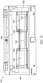
- Feederhousing 1200 generally includes an outer housing structure 1202 which defines a hollow 1204 therein.
- a feed drum 1206 is disposed within hollow 1204 and rotatably attached to outer housing structure 1202.
- Feed drum 1206 is rotated by belts 1208, and attached to belts 1208 are conveyor belt slats 1210 (five shown).
- the feed drum 1206, belts 1208 and conveyor belt slats 1210 are part of a larger structure called a mid-frame, an example of which is showing in FIG. 13 .
- Mid-frame 1300 includes feed drum 1302 which is attachable to an outer housing structure (not shown), and an axle with drive sprockets 1304.
- Belts 1306 are connected to both feed drum 1302 and corresponding drive sprockets 1304. Attached to belts 1306 are conveyor belt slats 1308 (ten shown).
Landscapes
- Engineering & Computer Science (AREA)
- Mechanical Engineering (AREA)
- General Engineering & Computer Science (AREA)
- Life Sciences & Earth Sciences (AREA)
- Environmental Sciences (AREA)
- Belt Conveyors (AREA)
Claims (5)
- Courroie (100), comprenant :- une couche de couverture (102) et une section dentée continue opposée (104) définissant une surface extérieure ;- un corps élastomérique réticulé (106) ; et,- une section de renfort tendue disposée entre la couche de couverture (102) et le corps élastomérique réticulé (106) ;dans laquelle la section dentée continue (104) est composée d'une pluralité de structures dentées ;dans laquelle chaque dent (116) de la pluralité de structures dentées comprend un flanc de dent (118), un méplat (120), et une zone de transition (122) entre le flanc de dent (118) et le méplat (120) ;dans laquelle la zone de transition (122) a une épaisseur radiale progressivement décroissante depuis le flanc de dent (118) jusqu'au méplat (120) ;caractérisée en ce que la courroie (100) est une courroie épissée ayant une épissure positionnée dans une structure dentée entre une paire de méplats correspondants (120) ; et,en ce que l'épissure comprend une paire de cordons en boucle (712) s'étendant depuis des extrémités (702, 704) de la section de renfort tendue, une paire de raccords d'accouplement (716) disposés entre la paire de cordons en boucle (712), un organe de serrage (718) disposé par-dessus la paire de raccords d'accouplement (716) et la paire de cordons en boucle (712) sur un côté de la courroie (100) comprenant la couche de couverture (102), et un organe de serrage inférieur (720) disposé sur une extrémité de l'une dent, dans laquelle un raccord d'organe de serrage (722) s'étend à travers l'organe de serrage (718) et entre la paire de raccords d'accouplement (716), et dans laquelle le raccord d'organe de serrage (722) entre fermement en prise avec l'organe de serrage inférieur (720).
- Courroie (100) selon la revendication 1, dans laquelle la zone de transition (122) a un angle de contact basse pression avec un pignon d'engrenage.
- Courroie (100) selon la revendication 2, dans laquelle l'angle de contact basse pression fournit une grande superficie de cisaillement.
- Courroie (100) selon les revendications précédentes et de celles-ci, dans laquelle un corps mort (726) est disposé à l'intérieur de chaque boucle comprise dans la paire de cordons en boucle (712).
- Courroie (100) selon la revendication 4, dans laquelle le corps mort (726) comprend une structure de soutien.
Applications Claiming Priority (2)
| Application Number | Priority Date | Filing Date | Title |
|---|---|---|---|
| US16/223,142 US10687468B1 (en) | 2018-12-18 | 2018-12-18 | Flexible synchronous toothed belt with narrow splice |
| PCT/EP2019/085868 WO2020127436A1 (fr) | 2018-12-18 | 2019-12-18 | Courroie crantée synchrone souple à épissure étroite |
Publications (2)
| Publication Number | Publication Date |
|---|---|
| EP3899319A1 EP3899319A1 (fr) | 2021-10-27 |
| EP3899319B1 true EP3899319B1 (fr) | 2025-06-11 |
Family
ID=69061347
Family Applications (1)
| Application Number | Title | Priority Date | Filing Date |
|---|---|---|---|
| EP19829122.1A Active EP3899319B1 (fr) | 2018-12-18 | 2019-12-18 | Courroie crantée synchrone souple à épissure étroite |
Country Status (3)
| Country | Link |
|---|---|
| US (1) | US10687468B1 (fr) |
| EP (1) | EP3899319B1 (fr) |
| WO (1) | WO2020127436A1 (fr) |
Families Citing this family (7)
| Publication number | Priority date | Publication date | Assignee | Title |
|---|---|---|---|---|
| DE102018222481A1 (de) * | 2018-12-20 | 2020-06-25 | Contitech Antriebssysteme Gmbh | Zugmittel, vorzugsweise Riemen, für einen Schrägförderer eines Mähdreschers |
| WO2022249027A1 (fr) * | 2021-05-24 | 2022-12-01 | Dayco Europe S.R.L. | Courroie de transmission |
| DE102021205907A1 (de) * | 2021-06-10 | 2022-12-15 | Contitech Antriebssysteme Gmbh | Verbindung |
| US12312177B2 (en) * | 2022-01-03 | 2025-05-27 | Fenner, Inc. | D-shaped belt with flanges |
| CN119604698A (zh) * | 2022-07-28 | 2025-03-11 | 阪东化学株式会社 | 带齿传送带 |
| US20250151651A1 (en) * | 2023-11-15 | 2025-05-15 | Contitech Antriebssysteme Gmbh | Synchronized feeder housing for a harvesting machine |
| US20250151652A1 (en) * | 2023-11-15 | 2025-05-15 | Contitech Antriebssysteme Gmbh | Conveying system with debris clearing device for harvesting machine |
Family Cites Families (79)
| Publication number | Priority date | Publication date | Assignee | Title |
|---|---|---|---|---|
| US608886A (en) * | 1898-08-09 | Rope-coupling | ||
| US383208A (en) * | 1888-05-22 | Belting | ||
| US1414278A (en) * | 1921-06-04 | 1922-04-25 | Hennigan Albert | Fan belt |
| US1505553A (en) * | 1923-02-26 | 1924-08-19 | Thomas E Gilmore | Clasp |
| US1570801A (en) * | 1924-11-06 | 1926-01-26 | Victor Balata & Textile Beltin | Belt clamp |
| US1897221A (en) * | 1931-02-07 | 1933-02-14 | Warner Arthur | Dead-end attachment |
| US2069385A (en) * | 1935-04-12 | 1937-02-02 | Flexible Steel Lacing Co | Belt fastener |
| US2113855A (en) * | 1936-08-24 | 1938-04-12 | Flexible Steel Lacing Co | Belt fastener |
| US2295029A (en) * | 1939-03-03 | 1942-09-08 | Goodrich Co B F | Power transmission belt |
| US2322967A (en) * | 1942-07-13 | 1943-06-29 | Reeves Pulley Co | Belt splice |
| US2449950A (en) * | 1945-02-13 | 1948-09-21 | Gates Rubber Co | Connector for belts |
| US2446311A (en) * | 1945-08-01 | 1948-08-03 | Goodrich Co B F | Power-transmission belt |
| US2814845A (en) * | 1954-11-04 | 1957-12-03 | Henry L Hanson Company | Belt connection |
| US2883871A (en) * | 1957-04-25 | 1959-04-28 | Hope Rubber Co Inc | Endless belt having connected end strips in a step arrangement |
| US3105390A (en) * | 1960-03-30 | 1963-10-01 | Funke Helmut | Means for fastening the reinforcement of belts |
| US3084408A (en) * | 1961-12-21 | 1963-04-09 | Ira Milton Jones | V-belt connector |
| US3618384A (en) * | 1970-02-05 | 1971-11-09 | Reliance Electric Co | Belt splice for v-pulley drive |
| US3664101A (en) * | 1970-09-11 | 1972-05-23 | Sperry Rand Corp | Crop gathering and converging reel |
| GB1378001A (en) * | 1971-04-16 | 1974-12-18 | Dunlop Ltd | Conveyor belts |
| US3851536A (en) * | 1973-02-16 | 1974-12-03 | Rockwell International Corp | Power transmission belt |
| GB1479269A (en) * | 1973-07-25 | 1977-07-13 | Massey Ferguson Sa | Crop harvesting and threshing machines |
| US3834245A (en) * | 1973-08-20 | 1974-09-10 | S Cultrera | Emergency v-belt for vehicles |
| DE2356072A1 (de) | 1973-11-09 | 1975-05-28 | Scholtz Ag Conrad | Vorrichtung zum verbinden von foerdergurten |
| US4690664A (en) * | 1978-11-02 | 1987-09-01 | Dayco Products, Inc. | Toothed belt |
| US4295837A (en) * | 1980-03-17 | 1981-10-20 | Dayco Corporation | Synchronous belt drive system |
| JPS5833423B2 (ja) * | 1980-10-28 | 1983-07-19 | 三ツ星ベルト株式会社 | 歯付ベルト |
| DE3142572C2 (de) * | 1981-10-27 | 1983-09-22 | Aumund-Fördererbau GmbH, Maschinenfabrik, 4134 Rheinberg | Vorrichtung zum lösbaren Verbinden von Seilenden, insbesondere von Seilen bei umlaufenden Seiltrieben, Seilförderern oder Aufhängungen |
| US4838843A (en) * | 1982-04-16 | 1989-06-13 | The Gates Rubber Company | Toothed belt |
| US4515577A (en) * | 1982-10-20 | 1985-05-07 | Uniroyal, Inc. | Low backlash-high-torque power transmission system and toothed belt used therein |
| US4540389A (en) * | 1983-04-01 | 1985-09-10 | Maxi-Lift, Inc. | Belt splicing device |
| US4553663A (en) * | 1984-05-10 | 1985-11-19 | The Goodyear Tire & Rubber Company | Conveyor for a crop harvester |
| US4722721A (en) * | 1984-11-15 | 1988-02-02 | Dayco Products, Inc. | Synchronous drive system and method of making the same |
| US4674803A (en) * | 1985-05-02 | 1987-06-23 | The Cincinnati Mine Machinery Company | Endless chains comprised of interdigitated link elements having an H-shaped configuration |
| US4717206A (en) * | 1985-05-02 | 1988-01-05 | The Cincinnati Mine Machinery Company | Endless chains comprised of interdigitated link elements having a Y-shaped configuration |
| FR2589542B1 (fr) * | 1985-10-30 | 1987-12-24 | Caoutchouc Manuf Plastique | Dispositif d'agrafage pour la jonction des courroies, procede de jonctionnement utilisant ce dispositif et courroie jonctionnee selon ce procede |
| FR2589543B1 (fr) * | 1985-10-30 | 1987-12-24 | Caoutchouc Manuf Plastique | Dispositif d'agrafage pour la jonction des courroies, procede de jonctionnement utilisant ce dispositif et courroie jonctionnee selon ce procede |
| US4776153A (en) * | 1986-02-27 | 1988-10-11 | Deere & Company | Automatic height control for a laterally pivoted harvester header |
| US4899868A (en) * | 1986-09-04 | 1990-02-13 | The Goodyear Tire & Rubber Company | Conveyor for a crop harvester |
| US5005922A (en) * | 1987-05-14 | 1991-04-09 | Edwards, Harper, Mcnew & Company | Double V-shaped endless track drive system |
| US5040282A (en) * | 1987-05-14 | 1991-08-20 | Edwards, Harper, Mcnew & Company | Method of making a modular endless track drive system |
| JPS6474341A (en) * | 1987-09-14 | 1989-03-20 | Mitsuboshi Belting Ltd | Driving device of toothed belt |
| USRE34485E (en) * | 1987-11-12 | 1993-12-21 | Mitsuboshi Belting, Ltd. | Power transmission toothed belt and drive |
| JPH0621604B2 (ja) * | 1988-01-27 | 1994-03-23 | バンドー化学株式会社 | 歯付ベルトおよびそのベルトを使用する動力伝達装置 |
| US5099548A (en) * | 1990-08-17 | 1992-03-31 | Loosli Curtis G | Quick splice for rod belt conveyor |
| US5114001A (en) * | 1991-08-05 | 1992-05-19 | Rexnord Corporation | Splice apparatus including splice plates with compound curvature |
| SE469950B (sv) * | 1992-02-28 | 1993-10-11 | Icl Data Ab | Skarvdon för kuggremmar |
| US5405299A (en) * | 1992-12-29 | 1995-04-11 | Bridgestone Corporation | Toothed belt and toothed belt-adapted pulley |
| US5362281A (en) * | 1993-04-08 | 1994-11-08 | The Gates Rubber Company | Toothed power transmission belt with fabric reinforcement |
| US5352488A (en) | 1993-05-14 | 1994-10-04 | Syracuse University | Chemical vapor deposition process employing metal pentadienyl complexes |
| FR2711409B1 (fr) * | 1993-10-20 | 1996-01-05 | Aser Sarl | Dispositif de jonctionnement pour bandes transporteuses et procédé de fixation dudit dispositif sur les extrémités de bandes transporteuses. |
| US5956811A (en) * | 1995-07-14 | 1999-09-28 | Rieter Machine Works, Ltd. | Revolving flat card |
| US6131728A (en) * | 1998-06-18 | 2000-10-17 | Precision Metal Fabricating Ltd. | Belt joint cover |
| US6352488B1 (en) * | 1999-03-05 | 2002-03-05 | The Goodyear Tire & Rubber Company | Power transmission belt |
| JP2000337444A (ja) * | 1999-03-25 | 2000-12-05 | Bando Chem Ind Ltd | 歯付ベルト及び歯付ベルト伝動装置並びに事務用機器 |
| JP2001227602A (ja) * | 2000-02-14 | 2001-08-24 | Tsubakimoto Chain Co | 歯付きベルト式伝動装置 |
| US6849016B2 (en) * | 2001-10-05 | 2005-02-01 | Delphi Technologies, Inc. | Over-molded beaded cable for driving applications |
| JP3964725B2 (ja) * | 2002-01-21 | 2007-08-22 | 本田技研工業株式会社 | 歯付きベルト伝動装置 |
| EP1338825B1 (fr) * | 2002-02-14 | 2005-08-17 | MATO Maschinen- und Metallwarenfabrik Curt Matthaei GmbH & Co KG | Jonction d'agrafes de courroie à crampons à une courroie et procédé |
| US6843744B2 (en) * | 2002-12-19 | 2005-01-18 | The Goodyear Tire & Rubber Company | Splicing joint and method for synchronous drive belt |
| US6896125B2 (en) * | 2003-04-04 | 2005-05-24 | Pflow Industries, Inc. | Belt attachment device and method |
| US7165628B2 (en) * | 2004-03-09 | 2007-01-23 | Art's-Way Manufacturing Co., Inc. | Continuous longitudinal flow root crop harvesting |
| US7695386B2 (en) | 2005-06-16 | 2010-04-13 | Veyance Technologies, Inc. | Fabric treatment for reinforced elastomeric articles |
| DE202005020662U1 (de) | 2005-08-03 | 2006-05-24 | SSI Schäfer PEEM GmbH | Verbindungseinheit für lose Zugmittelenden |
| US7412816B2 (en) * | 2006-03-02 | 2008-08-19 | Deere & Company | Sectionalized belt guide for draper belt in an agricultural harvesting machine |
| US8932165B2 (en) * | 2006-03-31 | 2015-01-13 | The Gates Corporation | Toothed power transmission belt |
| US8357065B2 (en) * | 2006-06-01 | 2013-01-22 | The Gates Corporation | Power transmission belt and a process for its manufacture |
| US8070634B2 (en) * | 2008-05-02 | 2011-12-06 | The Gates Corporation | Synchronous belt sprocket |
| US7650736B1 (en) * | 2008-07-16 | 2010-01-26 | Deere & Company | Center conveyor front coupler for a draper cutting platform |
| DE102009036104B4 (de) * | 2009-07-27 | 2012-02-09 | Artemis Kautschuk- Und Kunststoff-Technik Gmbh | Schrägförderer für Mähdrescher |
| US8635842B2 (en) * | 2009-08-05 | 2014-01-28 | Kevin Markt | Flexible row crop header for an agricultural harvester |
| DE102010037697A1 (de) * | 2010-09-22 | 2012-03-22 | Contitech Transportbandsysteme Gmbh | Stahlseilfördergurt mit einem Verbindungsscharnier zum Koppeln zweier Gurtenden |
| CH704969A1 (de) * | 2011-05-17 | 2012-11-30 | Habasit Ag | Riemen mit einer lösbaren Endverbindung. |
| CA2777084C (fr) * | 2012-05-08 | 2013-05-28 | John W. Houston | Dispositif de blocage d'ejection de produits de culture a partir d'une plateforme de tariere d'une recolteuse agricole |
| DE102012104477A1 (de) * | 2012-05-24 | 2013-11-28 | Contitech Transportbandsysteme Gmbh | Gurtendekörper oder Gurtsegmentendekörper |
| ES2746834T5 (en) * | 2015-04-09 | 2025-02-25 | Arnold Jaeger Holding Gmbh | Belt as endless traction mechanism for conveyor belts of agricultural machines |
| US9955628B2 (en) * | 2015-09-25 | 2018-05-01 | Deere & Company | Reversible drive system for an agricultural machine |
| US10514083B2 (en) * | 2016-08-16 | 2019-12-24 | Contitech Antriebssysteme Gmbh | Cross-linked elastomeric low friction faced synchronous power transmission belt |
| US10161487B2 (en) * | 2017-03-07 | 2018-12-25 | Gates Corporation | Toothed belt and sprocket system |
| US10288148B2 (en) * | 2017-05-31 | 2019-05-14 | Deere & Company | Feed conveyor belt and coupler |
-
2018
- 2018-12-18 US US16/223,142 patent/US10687468B1/en active Active
-
2019
- 2019-12-18 EP EP19829122.1A patent/EP3899319B1/fr active Active
- 2019-12-18 WO PCT/EP2019/085868 patent/WO2020127436A1/fr not_active Ceased
Also Published As
| Publication number | Publication date |
|---|---|
| WO2020127436A1 (fr) | 2020-06-25 |
| US10687468B1 (en) | 2020-06-23 |
| EP3899319A1 (fr) | 2021-10-27 |
| US20200187420A1 (en) | 2020-06-18 |
Similar Documents
| Publication | Publication Date | Title |
|---|---|---|
| EP3899319B1 (fr) | Courroie crantée synchrone souple à épissure étroite | |
| US4553663A (en) | Conveyor for a crop harvester | |
| US8596447B2 (en) | Inclined conveyor for a combine | |
| US4899868A (en) | Conveyor for a crop harvester | |
| US12054341B2 (en) | Center tracking dual synchronous belt system | |
| US11111079B2 (en) | Draper belt having improved edge durability | |
| EP3409099B1 (fr) | Courroie et coupleur pour transporteur d'alimentation | |
| US11382272B2 (en) | Traction belt for an inclined conveyor of a combine harvester | |
| EP3356262B1 (fr) | Courroie de tuloteuse ayant une configuration de tasseaux améliorée | |
| US20200045886A1 (en) | Slat-bar cross-members in a feederhouse crop-conveying system | |
| CA1296532C (fr) | Convoyeur pour un moissonneur | |
| EP3355681B1 (fr) | Bande transporteuse à toile avec pièce rapportée en caoutchouc à l'intérieur des éclisses | |
| WO2017150630A1 (fr) | Moissonneuse et moissonneuse-batteuse | |
| WO2023114796A1 (fr) | Jonction de chevauchement de courroie de convoyeur à toile | |
| US20250151651A1 (en) | Synchronized feeder housing for a harvesting machine | |
| US20250151652A1 (en) | Conveying system with debris clearing device for harvesting machine | |
| WO2023114797A1 (fr) | Ensembles de fixation de courroie de convoyeur à toile | |
| CA3000648C (fr) | Courroie de tuloteuse ayant une configuration de tasseaux amelioree |
Legal Events
| Date | Code | Title | Description |
|---|---|---|---|
| STAA | Information on the status of an ep patent application or granted ep patent |
Free format text: STATUS: UNKNOWN |
|
| STAA | Information on the status of an ep patent application or granted ep patent |
Free format text: STATUS: THE INTERNATIONAL PUBLICATION HAS BEEN MADE |
|
| PUAI | Public reference made under article 153(3) epc to a published international application that has entered the european phase |
Free format text: ORIGINAL CODE: 0009012 |
|
| STAA | Information on the status of an ep patent application or granted ep patent |
Free format text: STATUS: REQUEST FOR EXAMINATION WAS MADE |
|
| 17P | Request for examination filed |
Effective date: 20210719 |
|
| AK | Designated contracting states |
Kind code of ref document: A1 Designated state(s): AL AT BE BG CH CY CZ DE DK EE ES FI FR GB GR HR HU IE IS IT LI LT LU LV MC MK MT NL NO PL PT RO RS SE SI SK SM TR |
|
| DAV | Request for validation of the european patent (deleted) | ||
| DAX | Request for extension of the european patent (deleted) | ||
| STAA | Information on the status of an ep patent application or granted ep patent |
Free format text: STATUS: EXAMINATION IS IN PROGRESS |
|
| 17Q | First examination report despatched |
Effective date: 20231130 |
|
| RAP1 | Party data changed (applicant data changed or rights of an application transferred) |
Owner name: CONTITECH DEUTSCHLAND GMBH |
|
| GRAP | Despatch of communication of intention to grant a patent |
Free format text: ORIGINAL CODE: EPIDOSNIGR1 |
|
| STAA | Information on the status of an ep patent application or granted ep patent |
Free format text: STATUS: GRANT OF PATENT IS INTENDED |
|
| RIC1 | Information provided on ipc code assigned before grant |
Ipc: A01D 61/04 20060101ALN20250124BHEP Ipc: B65G 15/42 20060101ALI20250124BHEP Ipc: A01D 61/02 20060101ALI20250124BHEP Ipc: F16G 3/06 20060101ALI20250124BHEP Ipc: F16G 1/28 20060101AFI20250124BHEP |
|
| INTG | Intention to grant announced |
Effective date: 20250213 |
|
| P01 | Opt-out of the competence of the unified patent court (upc) registered |
Free format text: CASE NUMBER: APP_11505/2025 Effective date: 20250310 |
|
| GRAS | Grant fee paid |
Free format text: ORIGINAL CODE: EPIDOSNIGR3 |
|
| GRAA | (expected) grant |
Free format text: ORIGINAL CODE: 0009210 |
|
| STAA | Information on the status of an ep patent application or granted ep patent |
Free format text: STATUS: THE PATENT HAS BEEN GRANTED |
|
| AK | Designated contracting states |
Kind code of ref document: B1 Designated state(s): AL AT BE BG CH CY CZ DE DK EE ES FI FR GB GR HR HU IE IS IT LI LT LU LV MC MK MT NL NO PL PT RO RS SE SI SK SM TR |
|
| REG | Reference to a national code |
Ref country code: GB Ref legal event code: FG4D |
|
| REG | Reference to a national code |
Ref country code: CH Ref legal event code: EP |
|
| REG | Reference to a national code |
Ref country code: IE Ref legal event code: FG4D |
|
| REG | Reference to a national code |
Ref country code: DE Ref legal event code: R096 Ref document number: 602019071084 Country of ref document: DE |
|
| PG25 | Lapsed in a contracting state [announced via postgrant information from national office to epo] |
Ref country code: ES Free format text: LAPSE BECAUSE OF FAILURE TO SUBMIT A TRANSLATION OF THE DESCRIPTION OR TO PAY THE FEE WITHIN THE PRESCRIBED TIME-LIMIT Effective date: 20250611 Ref country code: FI Free format text: LAPSE BECAUSE OF FAILURE TO SUBMIT A TRANSLATION OF THE DESCRIPTION OR TO PAY THE FEE WITHIN THE PRESCRIBED TIME-LIMIT Effective date: 20250611 |
|
| REG | Reference to a national code |
Ref country code: LT Ref legal event code: MG9D |
|
| PG25 | Lapsed in a contracting state [announced via postgrant information from national office to epo] |
Ref country code: NO Free format text: LAPSE BECAUSE OF FAILURE TO SUBMIT A TRANSLATION OF THE DESCRIPTION OR TO PAY THE FEE WITHIN THE PRESCRIBED TIME-LIMIT Effective date: 20250911 Ref country code: GR Free format text: LAPSE BECAUSE OF FAILURE TO SUBMIT A TRANSLATION OF THE DESCRIPTION OR TO PAY THE FEE WITHIN THE PRESCRIBED TIME-LIMIT Effective date: 20250912 |
|
| REG | Reference to a national code |
Ref country code: NL Ref legal event code: MP Effective date: 20250611 |
|
| PG25 | Lapsed in a contracting state [announced via postgrant information from national office to epo] |
Ref country code: BG Free format text: LAPSE BECAUSE OF FAILURE TO SUBMIT A TRANSLATION OF THE DESCRIPTION OR TO PAY THE FEE WITHIN THE PRESCRIBED TIME-LIMIT Effective date: 20250611 |
|
| PG25 | Lapsed in a contracting state [announced via postgrant information from national office to epo] |
Ref country code: HR Free format text: LAPSE BECAUSE OF FAILURE TO SUBMIT A TRANSLATION OF THE DESCRIPTION OR TO PAY THE FEE WITHIN THE PRESCRIBED TIME-LIMIT Effective date: 20250611 |
|
| PG25 | Lapsed in a contracting state [announced via postgrant information from national office to epo] |
Ref country code: RS Free format text: LAPSE BECAUSE OF FAILURE TO SUBMIT A TRANSLATION OF THE DESCRIPTION OR TO PAY THE FEE WITHIN THE PRESCRIBED TIME-LIMIT Effective date: 20250911 |
|
| PG25 | Lapsed in a contracting state [announced via postgrant information from national office to epo] |
Ref country code: LV Free format text: LAPSE BECAUSE OF FAILURE TO SUBMIT A TRANSLATION OF THE DESCRIPTION OR TO PAY THE FEE WITHIN THE PRESCRIBED TIME-LIMIT Effective date: 20250611 |
|
| PG25 | Lapsed in a contracting state [announced via postgrant information from national office to epo] |
Ref country code: NL Free format text: LAPSE BECAUSE OF FAILURE TO SUBMIT A TRANSLATION OF THE DESCRIPTION OR TO PAY THE FEE WITHIN THE PRESCRIBED TIME-LIMIT Effective date: 20250611 |
|
| PG25 | Lapsed in a contracting state [announced via postgrant information from national office to epo] |
Ref country code: PT Free format text: LAPSE BECAUSE OF FAILURE TO SUBMIT A TRANSLATION OF THE DESCRIPTION OR TO PAY THE FEE WITHIN THE PRESCRIBED TIME-LIMIT Effective date: 20251013 |
|
| REG | Reference to a national code |
Ref country code: AT Ref legal event code: MK05 Ref document number: 1802484 Country of ref document: AT Kind code of ref document: T Effective date: 20250611 |
|
| PG25 | Lapsed in a contracting state [announced via postgrant information from national office to epo] |
Ref country code: IS Free format text: LAPSE BECAUSE OF FAILURE TO SUBMIT A TRANSLATION OF THE DESCRIPTION OR TO PAY THE FEE WITHIN THE PRESCRIBED TIME-LIMIT Effective date: 20251011 |
|
| PG25 | Lapsed in a contracting state [announced via postgrant information from national office to epo] |
Ref country code: AT Free format text: LAPSE BECAUSE OF FAILURE TO SUBMIT A TRANSLATION OF THE DESCRIPTION OR TO PAY THE FEE WITHIN THE PRESCRIBED TIME-LIMIT Effective date: 20250611 Ref country code: SM Free format text: LAPSE BECAUSE OF FAILURE TO SUBMIT A TRANSLATION OF THE DESCRIPTION OR TO PAY THE FEE WITHIN THE PRESCRIBED TIME-LIMIT Effective date: 20250611 |
|
| PGFP | Annual fee paid to national office [announced via postgrant information from national office to epo] |
Ref country code: BE Payment date: 20251219 Year of fee payment: 7 |
|
| PG25 | Lapsed in a contracting state [announced via postgrant information from national office to epo] |
Ref country code: CZ Free format text: LAPSE BECAUSE OF FAILURE TO SUBMIT A TRANSLATION OF THE DESCRIPTION OR TO PAY THE FEE WITHIN THE PRESCRIBED TIME-LIMIT Effective date: 20250611 |
|
| PG25 | Lapsed in a contracting state [announced via postgrant information from national office to epo] |
Ref country code: PL Free format text: LAPSE BECAUSE OF FAILURE TO SUBMIT A TRANSLATION OF THE DESCRIPTION OR TO PAY THE FEE WITHIN THE PRESCRIBED TIME-LIMIT Effective date: 20250611 |
|
| PG25 | Lapsed in a contracting state [announced via postgrant information from national office to epo] |
Ref country code: EE Free format text: LAPSE BECAUSE OF FAILURE TO SUBMIT A TRANSLATION OF THE DESCRIPTION OR TO PAY THE FEE WITHIN THE PRESCRIBED TIME-LIMIT Effective date: 20250611 |
|
| PG25 | Lapsed in a contracting state [announced via postgrant information from national office to epo] |
Ref country code: SK Free format text: LAPSE BECAUSE OF FAILURE TO SUBMIT A TRANSLATION OF THE DESCRIPTION OR TO PAY THE FEE WITHIN THE PRESCRIBED TIME-LIMIT Effective date: 20250611 Ref country code: RO Free format text: LAPSE BECAUSE OF FAILURE TO SUBMIT A TRANSLATION OF THE DESCRIPTION OR TO PAY THE FEE WITHIN THE PRESCRIBED TIME-LIMIT Effective date: 20250611 |
|
| PG25 | Lapsed in a contracting state [announced via postgrant information from national office to epo] |
Ref country code: DK Free format text: LAPSE BECAUSE OF FAILURE TO SUBMIT A TRANSLATION OF THE DESCRIPTION OR TO PAY THE FEE WITHIN THE PRESCRIBED TIME-LIMIT Effective date: 20250611 |
|
| PGFP | Annual fee paid to national office [announced via postgrant information from national office to epo] |
Ref country code: DE Payment date: 20251231 Year of fee payment: 7 |
|
| PG25 | Lapsed in a contracting state [announced via postgrant information from national office to epo] |
Ref country code: IT Free format text: LAPSE BECAUSE OF FAILURE TO SUBMIT A TRANSLATION OF THE DESCRIPTION OR TO PAY THE FEE WITHIN THE PRESCRIBED TIME-LIMIT Effective date: 20250611 |
|
| PLBE | No opposition filed within time limit |
Free format text: ORIGINAL CODE: 0009261 |
|
| STAA | Information on the status of an ep patent application or granted ep patent |
Free format text: STATUS: NO OPPOSITION FILED WITHIN TIME LIMIT |
|
| REG | Reference to a national code |
Ref country code: CH Ref legal event code: L10 Free format text: ST27 STATUS EVENT CODE: U-0-0-L10-L00 (AS PROVIDED BY THE NATIONAL OFFICE) Effective date: 20260423 |