EP3899329B1 - Vanne multi-plan à plusieurs orifices - Google Patents
Vanne multi-plan à plusieurs orifices Download PDFInfo
- Publication number
- EP3899329B1 EP3899329B1 EP19900548.9A EP19900548A EP3899329B1 EP 3899329 B1 EP3899329 B1 EP 3899329B1 EP 19900548 A EP19900548 A EP 19900548A EP 3899329 B1 EP3899329 B1 EP 3899329B1
- Authority
- EP
- European Patent Office
- Prior art keywords
- port
- plane
- ports
- fluid communication
- shell body
- Prior art date
- Legal status (The legal status is an assumption and is not a legal conclusion. Google has not performed a legal analysis and makes no representation as to the accuracy of the status listed.)
- Active
Links
Images


Classifications
-
- F—MECHANICAL ENGINEERING; LIGHTING; HEATING; WEAPONS; BLASTING
- F16—ENGINEERING ELEMENTS AND UNITS; GENERAL MEASURES FOR PRODUCING AND MAINTAINING EFFECTIVE FUNCTIONING OF MACHINES OR INSTALLATIONS; THERMAL INSULATION IN GENERAL
- F16K—VALVES; TAPS; COCKS; ACTUATING-FLOATS; DEVICES FOR VENTING OR AERATING
- F16K11/00—Multiple-way valves, e.g. mixing valves; Pipe fittings incorporating such valves
- F16K11/02—Multiple-way valves, e.g. mixing valves; Pipe fittings incorporating such valves with all movable sealing faces moving as one unit
- F16K11/08—Multiple-way valves, e.g. mixing valves; Pipe fittings incorporating such valves with all movable sealing faces moving as one unit comprising only taps or cocks
- F16K11/085—Multiple-way valves, e.g. mixing valves; Pipe fittings incorporating such valves with all movable sealing faces moving as one unit comprising only taps or cocks with cylindrical plug
- F16K11/0856—Multiple-way valves, e.g. mixing valves; Pipe fittings incorporating such valves with all movable sealing faces moving as one unit comprising only taps or cocks with cylindrical plug having all the connecting conduits situated in more than one plane perpendicular to the axis of the plug
-
- F—MECHANICAL ENGINEERING; LIGHTING; HEATING; WEAPONS; BLASTING
- F16—ENGINEERING ELEMENTS AND UNITS; GENERAL MEASURES FOR PRODUCING AND MAINTAINING EFFECTIVE FUNCTIONING OF MACHINES OR INSTALLATIONS; THERMAL INSULATION IN GENERAL
- F16K—VALVES; TAPS; COCKS; ACTUATING-FLOATS; DEVICES FOR VENTING OR AERATING
- F16K5/00—Plug valves; Taps or cocks comprising only cut-off apparatus having at least one of the sealing faces shaped as a more or less complete surface of a solid of revolution, the opening and closing movement being predominantly rotary
- F16K5/04—Plug valves; Taps or cocks comprising only cut-off apparatus having at least one of the sealing faces shaped as a more or less complete surface of a solid of revolution, the opening and closing movement being predominantly rotary with plugs having cylindrical surfaces; Packings therefor
- F16K5/0457—Packings
- F16K5/0471—Packings between housing and plug
-
- F—MECHANICAL ENGINEERING; LIGHTING; HEATING; WEAPONS; BLASTING
- F01—MACHINES OR ENGINES IN GENERAL; ENGINE PLANTS IN GENERAL; STEAM ENGINES
- F01P—COOLING OF MACHINES OR ENGINES IN GENERAL; COOLING OF INTERNAL-COMBUSTION ENGINES
- F01P7/00—Controlling of coolant flow
- F01P7/14—Controlling of coolant flow the coolant being liquid
- F01P2007/146—Controlling of coolant flow the coolant being liquid using valves
-
- F—MECHANICAL ENGINEERING; LIGHTING; HEATING; WEAPONS; BLASTING
- F01—MACHINES OR ENGINES IN GENERAL; ENGINE PLANTS IN GENERAL; STEAM ENGINES
- F01P—COOLING OF MACHINES OR ENGINES IN GENERAL; COOLING OF INTERNAL-COMBUSTION ENGINES
- F01P7/00—Controlling of coolant flow
- F01P7/14—Controlling of coolant flow the coolant being liquid
- F01P7/16—Controlling of coolant flow the coolant being liquid by thermostatic control
Definitions
- This invention generally relates to multi-port valves, and more particularly to multi-port valves having multiple inlet and outlet ports to control flow in different planes.
- Multi-port valves are used in a variety of industries and applications. Such valves include one or more inlet ports and one or more outlet ports.
- a valve member disposed within a housing of the valve is responsible for governing the flow between the various ports.
- Such multi-port valves advantageously provide a single flow device which can effectively replace multiple flow devices which only employ a single inlet and a single outlet.
- multi-port valves are not without their own drawbacks.
- the overall complexity of the valve increases as the number of ports increases. This can lead to relatively high part count assemblies.
- this complexity in construction also results in a more complex manufacturing process for making the valve.
- the multiple ports are associated with multiple inlets and outlets of the valve which must be welded onto a housing. Further the desired fitting for each inlet and outlet must also be welded on to its respective inlet or outlet.
- Such welded up assemblies increase the number of potential leak paths of the valve. Further, to achieve such welds, special machining steps are often needed at the inlets and outlets as well as the housing to ensure there is a tight fit between these components for subsequent welding.
- Multi-port valves that overcome these issues are available from the assignee of the instant application, and are described in U.S. Patent No. 9,212,751 ("Valve system and method” by Allan R. McLane et al.), issued December 15, 2015 , and co-pending U.S. Patent Application No. 15/945,173 (Publication No. 2018/0292016, "Multi-port valve” by Joe Ledvora et al.), filed April 4, 2018 , and claiming priority to U.S. Provisional Application No. 62/483,167, filed April 7, 2017 .
- Documents DE3844175 A1 , US2127679 A and EP3561346 A1 (which is a late published document, claiming the priority date of 24.04.2018 ) relate to multi-port, multi-plane valves.
- embodiments of the present invention provide a multi-port multi-plane valve having a reduced part count and a reduced cost relative to prior designs, and that provides multi-planar fluid flow and control.
- An embodiment of such a multi-port multi-plane valve is claimed in claim 1.
- An embodiment of a method of operating a multi-port, multi-plane valve is claimed in claim 10.
- Preferred embodiments are claimed in the dependent claims.
- the multi-port multi-plane valve advantageously overcomes existing problems in the art by presenting an overall construction with a reduced part count, a reduced number of potential leak paths, a reduction in overall assembly time and cost, and reduced external plumbing to provide fluid flow and control in multiple planes.
- multi-port valve assemblies typically, as here, include an actuator (not shown herein) mounted to the multi-port valve.
- the actuator is responsible for actuating a valve member (i.e., a shell body as described below) which in turn governs the flow characteristics through the valve.
- the actuator may be any style of actuator typically used in valve actuation, e.g., rotary, linear, etc., and may rely on any type of power source typically used in valve actuation, e.g., electric, hydraulic, and pneumatic, etc.
- Monitoring of the rotational position of the valving member may also utilize any type of position sensing, e.g., via a Hall-effect sensor, potentiometer, stepper motor control, etc.
- the actuator and position sensing are non-limiting on the invention herein.
- Valve 32 includes a housing 40.
- housing 40 is formed as a single piece.
- the main body of housing 40 and its associated ports are not an assembly of separate components which are subsequently joined together by a joining process, e.g., welding, as is done in conventional valve housings.
- housing 40 is formed as a single unitary piece by any process capable of achieving such a configuration, e.g. inj ection molding, 3D printing, etc.
- housing 40 may be embodied as an assembly of separate components which are subsequently joined together by a j oining process.
- housing 40 includes a plurality of ports, in particular, a first port 42, a second port 44, a third port 46, a fourth port 48, and a fifth port 50 (see FIG. 7 ) that lies in a plane or along an axis that is normal to the plane of the other four ports 42, 44, 46, 48 in the illustrated embodiment.
- a first port 42, a second port 44, a third port 46, a fourth port 48, and a fifth port 50 (see FIG. 7 ) that lies in a plane or along an axis that is normal to the plane of the other four ports 42, 44, 46, 48 in the illustrated embodiment.
- Each of the ports 42, 44, 46, 48, 50 are in fluid communication with an internal cavity 56 of housing 40.
- each of ports 42, 44, 46, 48, 50 may function as an inlet or an outlet, or both, of valve 32.
- internal cavity 56 receives a generally cylindrical shell body 58 which operates as a valve member for controlling the flows between the plurality of ports 42, 44, 46, 48, 50.
- a seal member 60 is also received in cavity 56 and surrounds the outer periphery of shell body 58.
- This seal member 58 is a continuous cylindrical element, except for the openings formed therein.
- seal member 60 is a single piece seal which advantageously creates a seal for each of the plurality of ports 42, 44, 46, 48 to prevent unintended cross flow or short circuiting.
- Seal member 60 also advantageously entirely seals internal cavity 56, such that no additional seals need be associated with port 50 or a cover 62 (see FIG. 7 ) of valve 32. It is possible, however, that seal member 60 may also be formed as separate seal segments which immediately next to one another in the circumferential direction, which together define a seal member which surrounds the shell body 58.
- seal member as used herein includes both configurations, i.e. a single unitary seal member, or a seal member formed of a plurality seal segments.
- Shell body 58 includes a plurality of openings.
- the openings of seal member 60 remain statically aligned with ports 42, 44, 46, 48, 50 so that each opening is associated with one port, and seals against an interior surface of housing 40 that defines cavity 56, around the opening of the port into cavity 56.
- Opening 20 and 22 in shell body 58 are selectively alignable with ports 42, 44, 46, 48, and opening 24 is aligned with port 50 to govern the flows between the ports.
- the shell body 58 includes a valve stem 64 (see FIG. 7 ) which extends through an opening in housing 40. This valve stem, and in turn the remainder of shell body 58, is rotatable about axis by an actuator as discussed above.
- a plurality of port bodies namely, a first port body 224, a second port body 226, a third port body 228, a fourth port body 230, and a fifth port body 232 (see FIG. 7 ) are respectively received in the first through fifth ports 42, 44, 46, 48, 50 as illustrated.
- the port bodies 224, 226, 228, 230 are substantially identical to one another, but port body 232 differs in the illustrated embodiment.
- Port body 224, 226, 228, 230 includes a through bore 238, 240, 242, 244 which communicates with an internal cavity 56 containing shell body 58 rotatably disposed therein through port 42, 44, 46, 48, respectively, of housing 40.
- Port body 232 provides passage through port 50 of housing 40 as shown in FIG. 7 .
- the shell body 58 is located in a first position referred to herein as 0°.
- the openings 20 and 24 provide fluid communication between ports 48 and 50 (see FIG. 7 ) and provide a change in the axis of flow between the two different planes in which the ports 48 and 50 lie.
- the opening 22 provides fluid communication between ports 42, 44, and 46. This communication is equal between ports 42 and 44, and may provide a 50% - 50% mix of fluid flow from ports 42, 44 into port 46, or vice versa, in certain implementations. Indeed, the percentage mix or flow can be varied between the ports 42, 44 by rotating the shell body 58 to provide a greater or lesser communication with opening 22.
- port 44 is isolated such that it has no fluid communication to any of the other ports. However, fluid communication is still provided between ports 42 and 46 (and between 48 and 50).
- a rotation of the shell body 58 about 24° from the orientation of FIG. 1 in the other direction as shown in FIG. 3 isolates port 42 such that it has no fluid communication to any of the other ports. However, fluid communication is still provided between ports 44 and 46 (and between 48 and 50).
- the angle of rotation is varied, the area of the openings 20 and 22 that is exposed to the particular port also varies once an edge of the opening moves past the seal 60 edge.
- FIGS. 4-6 illustrate similar rotational alignments as shown in FIGS. 1-3 , but starting with an orientation of the shell body 58 that is 180° from that shown in FIG. 1 .
- Such orientations provide fluid communication between ports 46 and 50, and variable mixing (or division) of flow between ports 42, 44, and 48, as well as isolation of ports 42 and 44 as discussed with regard to FIGS. 2 and 3 .
- FIGS. 7, 8 provide isometric side views of the embodiment of the multi-port multi-plane valve 32 shown with the shell body 58 positioned as shown in FIG. 1 when viewed into port body 224 and 228, respectively.
- FIG. 9 provides isometric side views of the embodiment of the multi-port multi-plane valve 32 shown with the shell body 58 positioned as shown in FIG. 2 when viewed into port body 228.
- FIGS. 10 and 11 there are illustrated isometric views of an embodiment of a multi-port multi-plane valve similar to that discussed hereinabove.
- the reference numerals have been removed and replaced with five port designations 1 - 5 to simplify the understanding of the operation thereof for the following description.
- the isometric cross-sectional view of FIG. 12 is also instructive as it illustrates the internal passages and the shell body with the same five port designations 1 - 5.
- FIG. 12 and the figures included thereafter introduce flow arrows and blocked flow symbols to aid in the understanding of the operation of the valve.
- valve 12-20 are not limiting on the flow direction through the valve, but instead only illustrate possible flows through the valve based on the communication enabled by the positioning of the shell body. Indeed, flow in other directions is also possible based on the external plumbing and flow system, and flow in both directions at different times through the same ports based on these external factors is also possible.
- the shell body is located in a first position referred to herein as 0°. In such position the shell body provides fluid communication between ports 3 and 5, and fluid communication between ports 1, 2, and 4. As the shell body is rotated, the percentage flow can be varied between the ports 2 and 4 to provide a greater or lesser flow from port 1.
- port 4 is isolated as shown by the blocked flow symbol such that it has no fluid communication to any of the other ports. However, fluid communication is still provided between ports 1 and 2 (and between 3 and 5).
- a rotation of the shell body about 24° from the orientation of FIG. 13 in the other direction as shown in FIG. 15 isolates port 2 as shown by the blocked flow symbol such that it has no fluid communication to any of the other ports. However, fluid communication is still provided between ports 1 and 4 (and between 3 and 5).
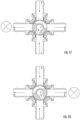
- FIGS. 16-18 illustrate similar rotational alignments as shown in FIGS. 13-15 , but starting with an orientation of the shell body that is 180° from that shown in FIG. 13 .
- Such orientations provide fluid communication between ports 1 and 5, and variable flow between ports 3, 2, and 4, as well as isolation of ports 4 and 2 as discussed with regard to FIGS. 14 and 15 .
- FIGS. 19 and 20 there is illustrated an embodiment of the multi-port, multi-plane valve that includes a shell body having a first and a second flow enhancer channel 20A, 20B provided on either side of the opening 20.
- These flow enhancer channels 20A, 20B also provide fluid communication to opening 24 leading to port 5, and operate to increase the flow thru the right angle opening when the shell body has been rotated to a position that is blocking the flow though one of the ports (4 in FIG. 19 and 2 in FIG. 20 ) on the other side of the valve.
- Such enhanced flow reduces the pressure drop occurring on one side of the valve when controlling flow paths on the other side of the valve.
- opening 20 is wider than the first flow enhancer channel 20A and wider than the second flow enhancer channel 20B.
- the first flow enhancer channel 20A has the same width as the second flow enhancer channel 20B.
- the multi-port multi-plane valve advantageously overcomes existing problems in the art by presenting an overall construction with a reduced part count, a reduced number of potential leak paths, and a reduction in overall assembly time and cost.
- the multi-port multi-plane valve has particular suitability for routing coolant in a thermal system, e.g., an engine or motor of a vehicle.
- the multi-port multi-plane valve can be used to route coolant in a first thermal loop and at least one other thermal loop.
- a first thermal loop may be to route the coolant to engine/motor components or a battery in need of cooling or warming
- a second thermal loop may be provided to cool or warm the coolant (e.g., to a radiator, chiller, or heater).
- the shell body 58 is able to be rotated to direct the flow of coolant through the desired thermal loops.
Landscapes
- Engineering & Computer Science (AREA)
- General Engineering & Computer Science (AREA)
- Mechanical Engineering (AREA)
- Multiple-Way Valves (AREA)
Claims (14)
- Une vanne multivoie et multiplan (32), comprenant :un boîtier (40) définissant une cavité interne (56) et comprenant une pluralité de ports (1, 2, 3, 4, 5, 42, 44, 46, 48, 50), chacun de la pluralité de ports étant en communication avec la cavité interne et au moins un port de la pluralité de ports se trouvant dans un premier plan normal à un second plan des autres ports de la pluralité de ports ; etun corps de coque (58) disposé de manière rotative dans la cavité interne (56) pour fournir sélectivement une communication fluidique plane entre un premier sous-ensemble de la pluralité de ports et une communication fluidique multiplan entre un second sous-ensemble de la pluralité de ports ;caractérisée en ce quele corps de coque comprend une ouverture et au moins un canal d'amélioration de l'écoulement (20A, 20B) disposé dans le second plan, l'au moins un canal d'amélioration de l'écoulement étant configuré pour réduire une chute de pression se produisant dans la communication fluidique multiplan lors de la variation de la communication fluidique multiplan entre le second sous-ensemble de la pluralité de ports.
- La vanne multivoie et multiplan selon la revendication 1, l'au moins un canal d'amélioration de l'écoulement comprenant un premier canal d'amélioration de l'écoulement disposé sur un premier côté de l'ouverture et un second canal d'amélioration de l'écoulement disposé sur un second côté de l'ouverture,de préférence, l'ouverture étant plus large que le premier canal d'amélioration de l'écoulement et plus large que le second canal d'amélioration de l'écoulement,de plus de préférence, le premier canal d'amélioration de l'écoulement ayant la même largeur que le second canal d'amélioration de l'écoulement.
- La vanne multivoie et multiplan selon la revendication 1 ou 2, l'au moins un port de la pluralité de ports comprenant un premier port et les autres ports de la pluralité de ports comprenant un second port, un troisième port, un quatrième port et un cinquième port.
- La vanne multivoie et multiplan selon la revendication 3, le corps de coque étant configuré pour fournir une communication fluidique multiplan entre le premier port et au maximum l'un du second port, troisième port, quatrième port ou cinquième port, quel que soit l'angle de rotation du corps de coque.
- La vanne multivoie et multiplan selon la revendication 3 ou 4, le corps de coque étant configuré pour fournir une communication fluidique plane entre au moins deux du second port, troisième port, quatrième port ou cinquième port, quel que soit l'angle de rotation du corps de coque.
- La vanne multivoie et multiplan selon l'une des revendications 3 à 5, le second port, le troisième port, le quatrième port et le cinquième port étant disposés à angle droit l'un par rapport à l'autre,de préférence, à un angle de rotation de référence de 0°, le second sous-ensemble de la pluralité de ports comprenant le premier port en communication fluidique multiplan avec le second port et le premier sous-ensemble de la pluralité de ports comprenant une communication fluidique plane entre le troisième port, le quatrième port et le cinquième port,de plus de préférence, à un angle de rotation d'environ 24° par rapport à l'angle de rotation de référence de 0°, le second sous-ensemble de la pluralité de ports comprenant le premier port en communication fluidique multiplan avec le second port, le troisième port étant isolé fluidiquement du quatrième port et du cinquième port, et le premier sous-ensemble de la pluralité de ports comprenant le quatrième port en communication fluidique plane avec le cinquième port.
- La vanne multivoie et multiplan selon l'une des revendications 1 à 6, le boîtier étant formé d'une seule pièce unitaire.
- La vanne multivoie et multiplan selon l'une des revendications 1 à 7, comprenant en outre un élément d'étanchéité disposé entre le corps de coque et le boîtier, l'élément d'étanchéité étant configuré pour empêcher un écoulement transversal involontaire entre la pluralité de ports.
- La vanne multivoie et multiplan selon la revendication 8, l'élément d'étanchéité étant une pièce unitaire unique, ou
l'élément d'étanchéité comprenant une pluralité de segments d'étanchéité et chacun des segments d'étanchéité étant disposé immédiatement à côté d'un autre segment d'étanchéité dans une direction circonférentielle. - Un procédé de fonctionnement d'une vanne multivoie et multiplan (32), la vanne multiport et multiplan comprenant un boîtier définissant une cavité interne (56), ayant un premier port (1, 42), un second port (2, 44), un troisième port (3, 46), et un quatrième port (4, 48) disposés dans un premier plan, et ayant un cinquième port (5, 50) disposé dans un second plan normal au premier plan et un corps de coque (58) disposé de manière rotative dans la cavité interne (56), le procédé comprenant l'étape de :faire tourner le corps de coque (58) dans la cavité interne (56) pour fournir une communication fluidique multiplan entre le cinquième port et l'un du premier port, second port, troisième port ou quatrième port, et une communication fluidique plane étant également fournie entre au moins deux autres ports du premier port, second port, troisième port ou quatrième port qui ne sont pas en communication fluidique multiplan avec le cinquième port ;caractérisé en ce quele corps de coque comprend une ouverture et au moins un canal d'amélioration de l'écoulement (20A, 20B) disposé dans le second plan, l'au moins un canal d'amélioration de l'écoulement étant configuré pour réduire une chute de pression se produisant dans la communication fluidique multiplan lors de la variation de la communication fluidique multiplan entre ledit cinquième port et ledit un du premier port, second port, troisième port ou quatrième port.
- Le procédé selon la revendication 10, l'étape de faire tourner comprenant en outre faire tourner le corps de coque à un angle de rotation de référence de 0° de sorte que le cinquième port est en communication fluidique multiplan avec le premier port et de sorte qu'une communication fluidique plane est fournie entre le second port, le troisième port et le quatrième port.
- Le procédé selon la revendication 11, comprenant en outre l'étape de diriger un écoulement fluidique multiplan du premier port vers le cinquième port et un écoulement fluidique plane du troisième port vers le second port et vers le quatrième port.
- Le procédé selon la revendication 11, comprenant en outre l'étape de faire tourner le corps de coque à un angle de rotation d'environ 24° par rapport à l'angle de rotation de référence de 0°, de sorte que le premier port est en communication fluidique multiplan avec le cinquième port, de sorte que le second port est isolé fluidiquement du troisième port et du quatrième port, et de sorte que le troisième port est en communication fluidique plane avec le quatrième port.
- Le procédé selon la revendication 13, comprenant en outre l'étape de diriger un écoulement fluidique multiplan du premier port vers le cinquième port et un écoulement fluidique plane du troisième port vers le quatrième port.
Applications Claiming Priority (3)
| Application Number | Priority Date | Filing Date | Title |
|---|---|---|---|
| US201862782155P | 2018-12-19 | 2018-12-19 | |
| US16/719,629 US11255450B2 (en) | 2018-12-19 | 2019-12-18 | Multi-port multi-plane valve |
| PCT/US2019/067499 WO2020132256A1 (fr) | 2018-12-19 | 2019-12-19 | Vanne multi-plan à plusieurs orifices |
Publications (3)
| Publication Number | Publication Date |
|---|---|
| EP3899329A1 EP3899329A1 (fr) | 2021-10-27 |
| EP3899329A4 EP3899329A4 (fr) | 2022-09-14 |
| EP3899329B1 true EP3899329B1 (fr) | 2024-11-20 |
Family
ID=71097530
Family Applications (1)
| Application Number | Title | Priority Date | Filing Date |
|---|---|---|---|
| EP19900548.9A Active EP3899329B1 (fr) | 2018-12-19 | 2019-12-19 | Vanne multi-plan à plusieurs orifices |
Country Status (5)
| Country | Link |
|---|---|
| US (2) | US11255450B2 (fr) |
| EP (1) | EP3899329B1 (fr) |
| CN (1) | CN113227620B (fr) |
| DE (1) | DE202019005792U1 (fr) |
| WO (1) | WO2020132256A1 (fr) |
Families Citing this family (19)
| Publication number | Priority date | Publication date | Assignee | Title |
|---|---|---|---|---|
| US11255450B2 (en) * | 2018-12-19 | 2022-02-22 | Robertshaw Controls Company | Multi-port multi-plane valve |
| DE102019210576A1 (de) * | 2019-07-17 | 2021-01-21 | Vitesco Technologies GmbH | Thermomanagementsystem, Fahrzeug und Verfahren zum Betreiben zweier Kühlkreisläufe eines Thermomanagementsystems |
| DE102020201190A1 (de) * | 2019-10-14 | 2021-04-15 | Vitesco Technologies GmbH | Fluidventil |
| US11773990B2 (en) | 2020-06-05 | 2023-10-03 | Robertshaw Controls Company | Multi-port multi-mode valve |
| DE102020207925A1 (de) * | 2020-06-25 | 2021-12-30 | Vitesco Technologies GmbH | Mischventil |
| WO2022143865A1 (fr) * | 2020-12-31 | 2022-07-07 | 浙江三花汽车零部件有限公司 | Ensemble de régulation de fluide et dispositif de régulation de fluide |
| US20220325820A1 (en) * | 2021-04-07 | 2022-10-13 | Shubhada Surve | Coolant Valve with Integrated Sensors |
| EP4356029B1 (fr) * | 2021-06-14 | 2025-07-30 | HELLA GmbH & Co. KGaA | Vanne à voies multiples pour un véhicule électrique, système de gestion thermique et procédé de fonctionnement d'un système de gestion thermique |
| WO2022263010A1 (fr) * | 2021-06-16 | 2022-12-22 | HELLA GmbH & Co. KGaA | Vanne à voies multiples pour système de refroidissement d'un véhicule électrique, système de refroidissement et véhicule électrique |
| EP4473235A1 (fr) * | 2022-03-07 | 2024-12-11 | Johnson Electric International AG | Soupape à orifices multiples à fonction d'écoulement proportionnel |
| CN118891465A (zh) * | 2022-03-07 | 2024-11-01 | 广东德昌电机有限公司 | 带比例流量功能的多端口阀门 |
| CN117146012A (zh) * | 2022-05-23 | 2023-12-01 | 浙江三花汽车零部件有限公司 | 一种控制阀 |
| US12152682B2 (en) * | 2022-07-06 | 2024-11-26 | Dana Automotive Systems Group, Llc | Serviceable valve and method for operation of said valve |
| US12359734B2 (en) * | 2022-08-25 | 2025-07-15 | Vitesco Technologies USA, LLC | Rotor for multiport coolant flow control valve assembly |
| KR20240053788A (ko) * | 2022-10-18 | 2024-04-25 | 현대자동차주식회사 | 제어 밸브 및 이를 포함하는 차량용 냉각 시스템 |
| US20240263710A1 (en) * | 2023-02-07 | 2024-08-08 | Hanon Systems | Fluid valve system |
| SE546806C2 (en) * | 2023-04-26 | 2025-02-25 | Lk Armatur Ab | A regulating valve and a fluid-based system |
| US12345339B2 (en) * | 2023-09-07 | 2025-07-01 | Textron Innovations, Inc. | Multi-way valve |
| KR20250084448A (ko) * | 2023-12-04 | 2025-06-11 | 현대자동차주식회사 | 다유로 밸브 및 이를 포함하는 히트 펌프 시스템 |
Family Cites Families (64)
| Publication number | Priority date | Publication date | Assignee | Title |
|---|---|---|---|---|
| US1422178A (en) | 1918-05-11 | 1922-07-11 | Vapor Car Heating Co Inc | Valve |
| GB270997A (en) | 1927-01-03 | 1927-05-19 | John Christopher Stead | Improvements relating to multiple way cocks or valves |
| US2127679A (en) * | 1937-04-28 | 1938-08-23 | Dudley Edward Clifford | Hydraulic control valve |
| US2492140A (en) * | 1944-01-22 | 1949-12-27 | Thompson Prod Inc | Fluid flow control device |
| GB905924A (en) | 1960-03-02 | 1962-09-12 | English Electric Co Ltd | Improvements in and relating to the control of the cooling water system of condensers, for example in a steam turbine plant |
| JPS48824Y1 (fr) | 1966-10-28 | 1973-01-10 | ||
| US3692041A (en) | 1971-01-04 | 1972-09-19 | Gen Electric | Variable flow distributor |
| JPS48824U (fr) * | 1971-05-24 | 1973-01-08 | ||
| US3927693A (en) | 1974-10-11 | 1975-12-23 | Minnesota Mining & Mfg | High-pressure valve |
| US4021190A (en) | 1975-08-20 | 1977-05-03 | Rockwell International Corporation | Burner block valve assembly |
| US4655252A (en) | 1980-03-24 | 1987-04-07 | Krumhansl Mark U | Valves |
| US4429717A (en) | 1981-09-04 | 1984-02-07 | Montgomery Robert N | Valve for controlling the flow of semi-liquid compositions |
| DE3236991A1 (de) | 1982-10-06 | 1984-04-12 | J.M. Voith Gmbh, 7920 Heidenheim | Streicheinrichtung fuer laufende warenbahnen |
| JPS5990665U (ja) * | 1982-12-10 | 1984-06-19 | 兼坂 一郎 | ガスコツク |
| US4909933A (en) | 1988-09-15 | 1990-03-20 | The United States Of America As Represented By The Administrator Of The National Aeronautics And Space Administration | Apparatus for mixing solutions in low gravity environments |
| DE3844175A1 (de) * | 1988-12-29 | 1990-07-05 | Fresenius Ag | Stroemungs-umkehrvorrichtung |
| US4968334A (en) | 1989-09-08 | 1990-11-06 | Hilton Thomas J | Remotely-controlled multi-port valve having a multi-vane rotating central drum element |
| US5084031A (en) | 1989-09-12 | 1992-01-28 | Research Medical, Inc. | Cardioplegia three-way double stopcock |
| US5431189A (en) | 1994-02-17 | 1995-07-11 | Jones; Ronald H. | Flow control manifold and gauge |
| US5529758A (en) | 1995-05-15 | 1996-06-25 | Houston; Reagan | Three-bed rotary valve and fume incineration system |
| NO975262L (no) * | 1996-11-19 | 1998-05-20 | Stolco Stoltenberg Lerche Gmbh | Dreneringskran |
| US5871032A (en) | 1997-08-01 | 1999-02-16 | Chung Cheng Faucet Co., Ltd. | Diverter valve assembly for control of multiple discharge in a mixing faucet |
| US6245233B1 (en) | 1997-11-26 | 2001-06-12 | Chih Wen Lu | Water filtering apparatus with water flow switch valve device |
| US6308739B1 (en) | 1998-02-13 | 2001-10-30 | Quality Controls, Inc. | Flexible rotor valve seal and ganged rotor valve incorporating same |
| US5931196A (en) | 1998-04-29 | 1999-08-03 | United States Filter Corporation | Bypass valve |
| KR100412805B1 (ko) | 2000-12-26 | 2003-12-31 | 현대자동차주식회사 | 멀티 유로 전환장치를 갖춘 버스용 슬라이딩도어 |
| US6918893B2 (en) | 2001-10-04 | 2005-07-19 | Scimed Life Systems, Inc. | Multiple port fluid control valves |
| US6681805B2 (en) * | 2001-11-28 | 2004-01-27 | Ranco Incorporated Of Delaware | Automotive coolant control valve |
| US6539899B1 (en) * | 2002-02-11 | 2003-04-01 | Visteon Global Technologies, Inc. | Rotary valve for single-point coolant diversion in engine cooling system |
| FR2844571B1 (fr) | 2002-09-18 | 2008-02-29 | Valeo Thermique Moteur Sa | Vanne de commande pour un circuit de fluide et circuit comportant cette vanne |
| US7059350B2 (en) | 2003-05-09 | 2006-06-13 | Hsin-Chi Chen | Airflow controlling mechanism |
| US20050006150A1 (en) | 2003-07-07 | 2005-01-13 | Power Chokes, L.P. | Solids strainer system for a hydraulic choke |
| JP4563770B2 (ja) | 2004-10-25 | 2010-10-13 | 株式会社山武 | 低騒音回転弁 |
| US7293660B2 (en) | 2004-12-22 | 2007-11-13 | Koo Chang Lin | Filter assembly having a five-way valve |
| US8881582B2 (en) | 2005-01-31 | 2014-11-11 | Waters Technologies Corporation | Method and apparatus for sample injection in liquid chromatography |
| FR2893113B1 (fr) * | 2005-11-04 | 2009-03-06 | Valeo Systemes Thermiques | Vanne de commande a etancheite amelioree pour circuit de circulation de fluide |
| US7506664B2 (en) | 2006-04-27 | 2009-03-24 | Ranco Incorporated Of Delaware | Automotive coolant control valve |
| US20080223464A1 (en) | 2007-03-15 | 2008-09-18 | Merrell Douglas E | Flow Diverters for Valves, Valves, and In-Floor Pool Cleaning Systems |
| US7837771B2 (en) | 2007-10-12 | 2010-11-23 | Hamilton Sundstrand Corporation | Rotary cylinder dual diverter valve |
| FR2940396B1 (fr) | 2008-12-22 | 2013-01-18 | Valeo Systemes Thermiques | Vanne d'alimentation en fluide d'une charge, echangeur de chaleur alimente par la vanne et moteur thermique a combustion interne comportant la vanne |
| US10476051B2 (en) | 2009-04-22 | 2019-11-12 | Tesla, Inc. | Battery pack base plate heat exchanger |
| US8557415B2 (en) | 2009-04-22 | 2013-10-15 | Tesla Motors, Inc. | Battery pack venting system |
| US8557416B2 (en) | 2009-04-22 | 2013-10-15 | Tesla Motors, Inc. | Battery pack directed venting system |
| US9371921B2 (en) | 2009-06-23 | 2016-06-21 | Nordson Corporation | Multi-port valve |
| US8336319B2 (en) | 2010-06-04 | 2012-12-25 | Tesla Motors, Inc. | Thermal management system with dual mode coolant loops |
| SE1150932A1 (sv) | 2011-10-10 | 2013-01-29 | Micael Toernblom | Ventil för administrering av ett flertal läkemedelsvätskor |
| DE102012100769A1 (de) | 2012-01-31 | 2013-08-01 | Benteler Automobiltechnik Gmbh | Abgaswegeventil |
| US8919378B2 (en) | 2012-04-04 | 2014-12-30 | GM Global Technology Operations LLC | Compact electrically controlled four-way valve with port mixing |
| US20140053931A1 (en) | 2012-08-23 | 2014-02-27 | Nordson, Inc. | Multiple port stopcock valve |
| FR2995964B1 (fr) | 2012-09-27 | 2014-10-10 | Systemes Moteurs | Vanne de distribution et de regulation a boisseau rotatif |
| US9212751B2 (en) | 2012-09-28 | 2015-12-15 | Robertshaw Controls Company | Valve system and method |
| JP6317080B2 (ja) | 2013-08-07 | 2018-04-25 | 株式会社不二工機 | シール部材及びそれを用いた流路切換弁 |
| US9321362B2 (en) | 2014-02-05 | 2016-04-26 | Tesia Motors, Inc. | Cooling of charging cable |
| EP2921750A1 (fr) | 2014-03-18 | 2015-09-23 | LK Armatur AB | Soupape |
| US9527403B2 (en) | 2014-04-29 | 2016-12-27 | Tesla Motors, Inc. | Charging station providing thermal conditioning of electric vehicle during charging session |
| US9803760B2 (en) | 2014-06-05 | 2017-10-31 | Schaeffler Technologies AG & Co. KG | Rotary valve with an isolating distribution body |
| US9865852B2 (en) | 2015-06-25 | 2018-01-09 | Tesla, Inc. | Energy storage container with vortex separator |
| US9687769B2 (en) | 2015-08-26 | 2017-06-27 | Tesla, Inc. | Vehicle air system with high efficiency filter |
| US10344877B2 (en) | 2015-12-01 | 2019-07-09 | Tesla Motors, Inc. | Multi-port valve with multiple operation modes |
| US10464397B2 (en) | 2016-03-03 | 2019-11-05 | Tesla, Inc. | Thermal system with high aspect ratio vent |
| JP6511427B2 (ja) * | 2016-12-19 | 2019-05-15 | 株式会社不二工機 | 流路切換弁 |
| US11655905B2 (en) | 2017-04-07 | 2023-05-23 | Robertshaw Controls Company | Multi-port valve |
| EP3561346B1 (fr) * | 2018-04-24 | 2022-06-08 | Vitesco Technologies GmbH | Joint d'étanchéité, dispositif d'étanchéité et soupape à voies multiples |
| US11255450B2 (en) * | 2018-12-19 | 2022-02-22 | Robertshaw Controls Company | Multi-port multi-plane valve |
-
2019
- 2019-12-18 US US16/719,629 patent/US11255450B2/en active Active
- 2019-12-19 EP EP19900548.9A patent/EP3899329B1/fr active Active
- 2019-12-19 WO PCT/US2019/067499 patent/WO2020132256A1/fr not_active Ceased
- 2019-12-19 CN CN201980083437.7A patent/CN113227620B/zh active Active
- 2019-12-19 DE DE202019005792.7U patent/DE202019005792U1/de active Active
-
2021
- 2021-09-27 US US17/485,788 patent/US11655906B2/en active Active
Also Published As
| Publication number | Publication date |
|---|---|
| EP3899329A4 (fr) | 2022-09-14 |
| WO2020132256A1 (fr) | 2020-06-25 |
| CN113227620A (zh) | 2021-08-06 |
| US11255450B2 (en) | 2022-02-22 |
| CN113227620B (zh) | 2023-07-04 |
| EP3899329A1 (fr) | 2021-10-27 |
| US11655906B2 (en) | 2023-05-23 |
| US20200200284A1 (en) | 2020-06-25 |
| DE202019005792U1 (de) | 2022-02-09 |
| US20220010884A1 (en) | 2022-01-13 |
Similar Documents
| Publication | Publication Date | Title |
|---|---|---|
| EP3899329B1 (fr) | Vanne multi-plan à plusieurs orifices | |
| US11773990B2 (en) | Multi-port multi-mode valve | |
| EP3385583B1 (fr) | Valve multiport | |
| JP7284771B2 (ja) | 弁 | |
| US11156300B2 (en) | Multi-port valve with partial circumferential seal arrangement | |
| JP7714971B2 (ja) | ロータリバルブ | |
| CN117881915B (zh) | 多端口阀门、具有该多端口阀门的热管理系统及其应用 | |
| JP6511427B2 (ja) | 流路切換弁 | |
| US10458562B2 (en) | Control valve | |
| CN111720591B (zh) | 分配阀和制冷系统 | |
| US20200173569A1 (en) | Integrated flow check for water/coolant valves | |
| US12359734B2 (en) | Rotor for multiport coolant flow control valve assembly | |
| US20230175599A1 (en) | Multi-port coolant flow control valve assembly | |
| CA2648426A1 (fr) | Soupape pour fluides | |
| CN117529625A (zh) | 多端口阀门及具有该多端口阀门的热管理系统 | |
| US11592116B2 (en) | Five port valve | |
| US12516743B2 (en) | Multi-port valve assembly | |
| WO2025092019A1 (fr) | Vanne multivoie, module intégré, système de gestion thermique et véhicule | |
| WO2024063071A1 (fr) | Dispositif de commutation de trajet d'écoulement | |
| JP2025022228A (ja) | 電動弁 | |
| CN119244775A (zh) | 多通阀及热管理系统 |
Legal Events
| Date | Code | Title | Description |
|---|---|---|---|
| STAA | Information on the status of an ep patent application or granted ep patent |
Free format text: STATUS: THE INTERNATIONAL PUBLICATION HAS BEEN MADE |
|
| PUAI | Public reference made under article 153(3) epc to a published international application that has entered the european phase |
Free format text: ORIGINAL CODE: 0009012 |
|
| STAA | Information on the status of an ep patent application or granted ep patent |
Free format text: STATUS: REQUEST FOR EXAMINATION WAS MADE |
|
| 17P | Request for examination filed |
Effective date: 20210610 |
|
| AK | Designated contracting states |
Kind code of ref document: A1 Designated state(s): AL AT BE BG CH CY CZ DE DK EE ES FI FR GB GR HR HU IE IS IT LI LT LU LV MC MK MT NL NO PL PT RO RS SE SI SK SM TR |
|
| DAV | Request for validation of the european patent (deleted) | ||
| DAX | Request for extension of the european patent (deleted) | ||
| A4 | Supplementary search report drawn up and despatched |
Effective date: 20220817 |
|
| RIC1 | Information provided on ipc code assigned before grant |
Ipc: F16K 11/087 20060101ALI20220810BHEP Ipc: F16K 5/06 20060101AFI20220810BHEP |
|
| GRAP | Despatch of communication of intention to grant a patent |
Free format text: ORIGINAL CODE: EPIDOSNIGR1 |
|
| STAA | Information on the status of an ep patent application or granted ep patent |
Free format text: STATUS: GRANT OF PATENT IS INTENDED |
|
| INTG | Intention to grant announced |
Effective date: 20240201 |
|
| GRAJ | Information related to disapproval of communication of intention to grant by the applicant or resumption of examination proceedings by the epo deleted |
Free format text: ORIGINAL CODE: EPIDOSDIGR1 |
|
| STAA | Information on the status of an ep patent application or granted ep patent |
Free format text: STATUS: REQUEST FOR EXAMINATION WAS MADE |
|
| GRAP | Despatch of communication of intention to grant a patent |
Free format text: ORIGINAL CODE: EPIDOSNIGR1 |
|
| STAA | Information on the status of an ep patent application or granted ep patent |
Free format text: STATUS: GRANT OF PATENT IS INTENDED |
|
| INTC | Intention to grant announced (deleted) | ||
| INTG | Intention to grant announced |
Effective date: 20240619 |
|
| GRAS | Grant fee paid |
Free format text: ORIGINAL CODE: EPIDOSNIGR3 |
|
| GRAA | (expected) grant |
Free format text: ORIGINAL CODE: 0009210 |
|
| STAA | Information on the status of an ep patent application or granted ep patent |
Free format text: STATUS: THE PATENT HAS BEEN GRANTED |
|
| AK | Designated contracting states |
Kind code of ref document: B1 Designated state(s): AL AT BE BG CH CY CZ DE DK EE ES FI FR GB GR HR HU IE IS IT LI LT LU LV MC MK MT NL NO PL PT RO RS SE SI SK SM TR |
|
| REG | Reference to a national code |
Ref country code: GB Ref legal event code: FG4D |
|
| REG | Reference to a national code |
Ref country code: CH Ref legal event code: EP |
|
| REG | Reference to a national code |
Ref country code: DE Ref legal event code: R096 Ref document number: 602019062409 Country of ref document: DE |
|
| REG | Reference to a national code |
Ref country code: IE Ref legal event code: FG4D |
|
| REG | Reference to a national code |
Ref country code: LT Ref legal event code: MG9D |
|
| REG | Reference to a national code |
Ref country code: NL Ref legal event code: MP Effective date: 20241120 |
|
| PG25 | Lapsed in a contracting state [announced via postgrant information from national office to epo] |
Ref country code: PT Free format text: LAPSE BECAUSE OF FAILURE TO SUBMIT A TRANSLATION OF THE DESCRIPTION OR TO PAY THE FEE WITHIN THE PRESCRIBED TIME-LIMIT Effective date: 20250320 Ref country code: HR Free format text: LAPSE BECAUSE OF FAILURE TO SUBMIT A TRANSLATION OF THE DESCRIPTION OR TO PAY THE FEE WITHIN THE PRESCRIBED TIME-LIMIT Effective date: 20241120 Ref country code: IS Free format text: LAPSE BECAUSE OF FAILURE TO SUBMIT A TRANSLATION OF THE DESCRIPTION OR TO PAY THE FEE WITHIN THE PRESCRIBED TIME-LIMIT Effective date: 20250320 |
|
| PG25 | Lapsed in a contracting state [announced via postgrant information from national office to epo] |
Ref country code: FI Free format text: LAPSE BECAUSE OF FAILURE TO SUBMIT A TRANSLATION OF THE DESCRIPTION OR TO PAY THE FEE WITHIN THE PRESCRIBED TIME-LIMIT Effective date: 20241120 Ref country code: NL Free format text: LAPSE BECAUSE OF FAILURE TO SUBMIT A TRANSLATION OF THE DESCRIPTION OR TO PAY THE FEE WITHIN THE PRESCRIBED TIME-LIMIT Effective date: 20241120 |
|
| REG | Reference to a national code |
Ref country code: AT Ref legal event code: MK05 Ref document number: 1743844 Country of ref document: AT Kind code of ref document: T Effective date: 20241120 |
|
| PG25 | Lapsed in a contracting state [announced via postgrant information from national office to epo] |
Ref country code: BG Free format text: LAPSE BECAUSE OF FAILURE TO SUBMIT A TRANSLATION OF THE DESCRIPTION OR TO PAY THE FEE WITHIN THE PRESCRIBED TIME-LIMIT Effective date: 20241120 |
|
| PG25 | Lapsed in a contracting state [announced via postgrant information from national office to epo] |
Ref country code: ES Free format text: LAPSE BECAUSE OF FAILURE TO SUBMIT A TRANSLATION OF THE DESCRIPTION OR TO PAY THE FEE WITHIN THE PRESCRIBED TIME-LIMIT Effective date: 20241120 |
|
| PG25 | Lapsed in a contracting state [announced via postgrant information from national office to epo] |
Ref country code: NO Free format text: LAPSE BECAUSE OF FAILURE TO SUBMIT A TRANSLATION OF THE DESCRIPTION OR TO PAY THE FEE WITHIN THE PRESCRIBED TIME-LIMIT Effective date: 20250220 |
|
| PG25 | Lapsed in a contracting state [announced via postgrant information from national office to epo] |
Ref country code: GR Free format text: LAPSE BECAUSE OF FAILURE TO SUBMIT A TRANSLATION OF THE DESCRIPTION OR TO PAY THE FEE WITHIN THE PRESCRIBED TIME-LIMIT Effective date: 20250221 Ref country code: AT Free format text: LAPSE BECAUSE OF FAILURE TO SUBMIT A TRANSLATION OF THE DESCRIPTION OR TO PAY THE FEE WITHIN THE PRESCRIBED TIME-LIMIT Effective date: 20241120 Ref country code: LV Free format text: LAPSE BECAUSE OF FAILURE TO SUBMIT A TRANSLATION OF THE DESCRIPTION OR TO PAY THE FEE WITHIN THE PRESCRIBED TIME-LIMIT Effective date: 20241120 |
|
| PG25 | Lapsed in a contracting state [announced via postgrant information from national office to epo] |
Ref country code: PL Free format text: LAPSE BECAUSE OF FAILURE TO SUBMIT A TRANSLATION OF THE DESCRIPTION OR TO PAY THE FEE WITHIN THE PRESCRIBED TIME-LIMIT Effective date: 20241120 |
|
| PG25 | Lapsed in a contracting state [announced via postgrant information from national office to epo] |
Ref country code: RS Free format text: LAPSE BECAUSE OF FAILURE TO SUBMIT A TRANSLATION OF THE DESCRIPTION OR TO PAY THE FEE WITHIN THE PRESCRIBED TIME-LIMIT Effective date: 20250220 |
|
| PG25 | Lapsed in a contracting state [announced via postgrant information from national office to epo] |
Ref country code: SM Free format text: LAPSE BECAUSE OF FAILURE TO SUBMIT A TRANSLATION OF THE DESCRIPTION OR TO PAY THE FEE WITHIN THE PRESCRIBED TIME-LIMIT Effective date: 20241120 |
|
| PG25 | Lapsed in a contracting state [announced via postgrant information from national office to epo] |
Ref country code: DK Free format text: LAPSE BECAUSE OF FAILURE TO SUBMIT A TRANSLATION OF THE DESCRIPTION OR TO PAY THE FEE WITHIN THE PRESCRIBED TIME-LIMIT Effective date: 20241120 |
|
| PG25 | Lapsed in a contracting state [announced via postgrant information from national office to epo] |
Ref country code: EE Free format text: LAPSE BECAUSE OF FAILURE TO SUBMIT A TRANSLATION OF THE DESCRIPTION OR TO PAY THE FEE WITHIN THE PRESCRIBED TIME-LIMIT Effective date: 20241120 |
|
| PG25 | Lapsed in a contracting state [announced via postgrant information from national office to epo] |
Ref country code: RO Free format text: LAPSE BECAUSE OF FAILURE TO SUBMIT A TRANSLATION OF THE DESCRIPTION OR TO PAY THE FEE WITHIN THE PRESCRIBED TIME-LIMIT Effective date: 20241120 |
|
| PG25 | Lapsed in a contracting state [announced via postgrant information from national office to epo] |
Ref country code: SK Free format text: LAPSE BECAUSE OF FAILURE TO SUBMIT A TRANSLATION OF THE DESCRIPTION OR TO PAY THE FEE WITHIN THE PRESCRIBED TIME-LIMIT Effective date: 20241120 |
|
| PG25 | Lapsed in a contracting state [announced via postgrant information from national office to epo] |
Ref country code: CZ Free format text: LAPSE BECAUSE OF FAILURE TO SUBMIT A TRANSLATION OF THE DESCRIPTION OR TO PAY THE FEE WITHIN THE PRESCRIBED TIME-LIMIT Effective date: 20241120 |
|
| REG | Reference to a national code |
Ref country code: CH Ref legal event code: PL |
|
| PG25 | Lapsed in a contracting state [announced via postgrant information from national office to epo] |
Ref country code: LU Free format text: LAPSE BECAUSE OF NON-PAYMENT OF DUE FEES Effective date: 20241219 |
|
| REG | Reference to a national code |
Ref country code: DE Ref legal event code: R097 Ref document number: 602019062409 Country of ref document: DE |
|
| PG25 | Lapsed in a contracting state [announced via postgrant information from national office to epo] |
Ref country code: SE Free format text: LAPSE BECAUSE OF FAILURE TO SUBMIT A TRANSLATION OF THE DESCRIPTION OR TO PAY THE FEE WITHIN THE PRESCRIBED TIME-LIMIT Effective date: 20241120 |
|
| PG25 | Lapsed in a contracting state [announced via postgrant information from national office to epo] |
Ref country code: MC Free format text: LAPSE BECAUSE OF FAILURE TO SUBMIT A TRANSLATION OF THE DESCRIPTION OR TO PAY THE FEE WITHIN THE PRESCRIBED TIME-LIMIT Effective date: 20241120 |
|
| PLBE | No opposition filed within time limit |
Free format text: ORIGINAL CODE: 0009261 |
|
| STAA | Information on the status of an ep patent application or granted ep patent |
Free format text: STATUS: NO OPPOSITION FILED WITHIN TIME LIMIT |
|
| REG | Reference to a national code |
Ref country code: BE Ref legal event code: MM Effective date: 20241231 |
|
| PG25 | Lapsed in a contracting state [announced via postgrant information from national office to epo] |
Ref country code: BE Free format text: LAPSE BECAUSE OF NON-PAYMENT OF DUE FEES Effective date: 20241231 |
|
| PG25 | Lapsed in a contracting state [announced via postgrant information from national office to epo] |
Ref country code: FR Free format text: LAPSE BECAUSE OF NON-PAYMENT OF DUE FEES Effective date: 20250120 |
|
| PG25 | Lapsed in a contracting state [announced via postgrant information from national office to epo] |
Ref country code: CH Free format text: LAPSE BECAUSE OF NON-PAYMENT OF DUE FEES Effective date: 20241231 |
|
| 26N | No opposition filed |
Effective date: 20250821 |
|
| PG25 | Lapsed in a contracting state [announced via postgrant information from national office to epo] |
Ref country code: IE Free format text: LAPSE BECAUSE OF NON-PAYMENT OF DUE FEES Effective date: 20241219 |
|
| PGFP | Annual fee paid to national office [announced via postgrant information from national office to epo] |
Ref country code: DE Payment date: 20250930 Year of fee payment: 7 |
|
| PGFP | Annual fee paid to national office [announced via postgrant information from national office to epo] |
Ref country code: GB Payment date: 20251001 Year of fee payment: 7 |
|
| PGFP | Annual fee paid to national office [announced via postgrant information from national office to epo] |
Ref country code: IT Payment date: 20251121 Year of fee payment: 7 |