EP3899560B1 - Procédé et système de surveillance de l'état d'un équipement électrique - Google Patents
Procédé et système de surveillance de l'état d'un équipement électrique Download PDFInfo
- Publication number
- EP3899560B1 EP3899560B1 EP18944113.2A EP18944113A EP3899560B1 EP 3899560 B1 EP3899560 B1 EP 3899560B1 EP 18944113 A EP18944113 A EP 18944113A EP 3899560 B1 EP3899560 B1 EP 3899560B1
- Authority
- EP
- European Patent Office
- Prior art keywords
- partial discharge
- electrical equipment
- data
- component
- impulses
- Prior art date
- Legal status (The legal status is an assumption and is not a legal conclusion. Google has not performed a legal analysis and makes no representation as to the accuracy of the status listed.)
- Active
Links
Images


Classifications
-
- G—PHYSICS
- G01—MEASURING; TESTING
- G01R—MEASURING ELECTRIC VARIABLES; MEASURING MAGNETIC VARIABLES
- G01R31/00—Arrangements for testing electric properties; Arrangements for locating electric faults; Arrangements for electrical testing characterised by what is being tested not provided for elsewhere
- G01R31/12—Testing dielectric strength or breakdown voltage ; Testing or monitoring effectiveness or level of insulation, e.g. of a cable or of an apparatus, for example using partial discharge measurements; Electrostatic testing
- G01R31/1227—Testing dielectric strength or breakdown voltage ; Testing or monitoring effectiveness or level of insulation, e.g. of a cable or of an apparatus, for example using partial discharge measurements; Electrostatic testing of components, parts or materials
- G01R31/1263—Testing dielectric strength or breakdown voltage ; Testing or monitoring effectiveness or level of insulation, e.g. of a cable or of an apparatus, for example using partial discharge measurements; Electrostatic testing of components, parts or materials of solid or fluid materials, e.g. insulation films, bulk material; of semiconductors or LV electronic components or parts; of cable, line or wire insulation
- G01R31/1272—Testing dielectric strength or breakdown voltage ; Testing or monitoring effectiveness or level of insulation, e.g. of a cable or of an apparatus, for example using partial discharge measurements; Electrostatic testing of components, parts or materials of solid or fluid materials, e.g. insulation films, bulk material; of semiconductors or LV electronic components or parts; of cable, line or wire insulation of cable, line or wire insulation, e.g. using partial discharge measurements
Definitions
- Partial discharge is a localized dielectric breakdown of a small portion of a solid or fluid electrical insulation system under high voltage stress, which does not bridge the space between two conductors. Protracted partial discharge can erode solid insulation and eventually lead to breakdown of insulation.
- Fractal dimension is a method to describe complex shapes, such as coastlines and mountains, by using fractal sets [9], while entropy is a measure of uncertainty in a signal.
- fractal dimension is used to separate PD signals from the noise, which locates in distinctive power cycles from the PD signals.
- the third data comprise a histogram of the second data, the histogram representing a distribution of magnitudes of the detected partial discharge impulses over phase angles of the detected partial discharge impulses.
- obtaining the frequency of the grid comprises: performing a Fourier transform on the detected partial discharge impulses; and calculating the frequency of the grid in consideration of a frequency of an impulse with a maximum magnitude among the transformed partial discharge impulses as the frequency of the grid.
- the one or more properties of the electrical equipment comprise: a type of partial discharge generating the partial discharge impulses, and/or a location where partial discharge generating the partial discharge impulses occurs.
- example embodiments of the present disclosure provide an Internet of Things (IoT) system.
- the Internet of Things comprises a system for condition monitoring an electrical equipment of the second aspect.
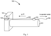
- condition monitoring electrical equipment As mentioned above, it is important to detect partial discharge so as to carry out condition monitoring electrical equipment. Although many efforts have been devoted to the condition monitoring, most of existing condition monitoring methods have disadvantages in various aspects. For example, most of the methods require detecting additional signals, such as a synchronization signal from a potential transformer (PT) via cumbersome wire routing.
- PT potential transformer
- partial discharge monitoring module 102 When partial discharge impulses are detected by the partial discharge monitoring module 102, the partial discharge monitoring module 102 needs to obtain a synchronization signal from the potential transformer 104. Based on the detected partial discharge impulses and the synchronization signal, partial discharge monitoring is carried out.
- a conventional partial discharge monitoring solution will be described in detail below with reference to the Figs. 2A-2C .
- a 50 Hz synchronization signal measured from the potential transformer 104 is unavoidable. Yet the potential transformer 104 is not always easy to access in electrical equipment 101. Furthermore, the voltage measured from the potential transformer 104 might not always be phase-consistent with the electrical stress applied on insulation. This can result in a monitoring error and increase condition monitoring cost.
- a solution for condition monitoring electrical equipment In this solution, features of the partial discharge impulses composed of its normalized histogram harmonics are extracted, based on an internal synchronization signal with a detected frequency of a grid. The features of the partial discharge impulses are shifted in consideration of their phase information. A signal indicating a health state of the electrical equipment is generated by comparing the shifted features of the partial discharge impulses with their counterparts associated with an unhealthy electrical equipment. In this way, it is helpful for monitoring the health state of the electrical equipment in a precise manner without relying on potential transformer signal for synchronization, thus facilitates quicker and easier deployment of the distributed partial discharge monitoring system.
- Example embodiments of the present disclosure will be described in detail below with reference to the figures.
- the electrical equipment 301 to be monitored may be any type of electrical equipment, such as a circuit breaker (CB), a power converter, and the like.
- CB circuit breaker
- power converter power converter
- the system 310 includes a detecting unit 302.
- the detecting unit 302 is configured to detect partial discharge impulses generated in the electrical equipment 301.
- the detecting unit 302 may be any type of detecting unit, such as a Ultra High Frequency (UHF) sensor, a Transient Earth Voltage (TEV) sensor or a High Frequency Current Transformer (HFCT), and the like.
- UHF Ultra High Frequency
- TAV Transient Earth Voltage
- HFCT High Frequency Current Transformer
- the detecting unit 302 is mounted on a case (or other positions easy to access) of the electrical equipment 301.
- the detecting unit 302 detects partial discharge impulses generated in the electrical equipment 301, and communicates with as a processing unit 311, through wireless channels like Bluetooth, Wi-Fi or wired channels.
- the system 310 further includes the processing unit 311 and a memory 312.
- the memory 312 is configured to store instructions. The instructions are executed by the processing unit 311, causing the system 310 to monitor the condition of the electrical equipment 301, as will be described below.
- the processing unit 311 may be any type of processing unit, such as a controller, a microcontroller or a Digital Signal Processor (DSP), and the like. It is to be understood that, the system 310 may include other units and/or modules not shown in Fig. 3 , such as a communication unit, an input/output unit, and the like.
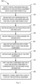
- Fig. 4 illustrates a flowchart of a process of condition monitoring electrical equipment 301 with some example embodiments of the present disclosure.
- the process 400 may be implemented in software and/or firmware by means of, for example, a system 310.
- partial discharge impulses are detected by the system 310.
- partial discharge impulses are generated in the electrical equipment 301 for at least one power cycle. During every power cycle, these partial discharge impulses may randomly occur at any phase angle, and their magnitudes may be uncertain as well.
- the system 310 obtains first data representing the detected partial discharge impulses for the at least one power cycle.
- it is required to have a synchronization signal with a frequency synchronized with a frequency of a grid. If a fixed-frequency 50 Hz waveform is used as the synchronization signal, most of the detected partial discharge impulses would become noises. This is because the real frequency of the grid may be deviated from 50 Hz. In this case, the system 310 would not be able to accurately monitor the condition of the electrical equipment 301.
- a Fourier transform may be applied on the detected partial discharge impulses. Then the frequency of the grid in consideration of a frequency of an impulse with a maximum magnitude among the transformed partial discharge impulses is determined as the frequency of the grid.
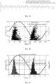
- Fig. 5A illustrates a diagram showing the detected partial discharge impulses in accordance with some example embodiments of the present disclosure. As shown in Fig. 5A , the horizontal axis represents time, the vertical axis represents magnitude, and the dots represent the detected partial discharge impulses.
- Fig. 5B illustrates a diagram showing a Fourier transform result of the detected partial discharge impulses of Fig. 5A in accordance with some example embodiments of the present disclosure.
- the horizontal axis represents frequency
- the vertical axis represents magnitude.
- the system 310 can selected a frequency of an impulse with a maximum magnitude among the transformed partial discharge impulses. It is to be noted that the selected raw frequency is twice the frequency of the grid, because the partial discharge impulses are generated from non-polarity sensors like UHF. Thus, if a non-polarity type sensor is used to detect the partial discharge impulses, the frequency of the grid should be half of the frequency of the impulse with a maximum magnitude, as shown in Fig. 5B . Alternatively, or in addition, if a polarity type sensor is used to detect the partial discharge impulses, the frequency of the grid should be the frequency of the impulse with a maximum magnitude. In this way, the system 310 can directly obtain the accurate frequency of the grid without accessing the potential transformer to obtain a synchronization signal. Therefore the detection accuracy is improved while the cost is reduced.
- an antenna for example a floating metal, can be added to the detecting unit 302. Therefore, the detecting unit 302 can sense the alternating ambient electromagnetic field.
- a frequency of a sensed fundamental waveform may be obtained as the frequency of the grid.
- Fig. 5C illustrates a voltage waveform displayed by an oscilloscope in accordance with some example embodiments of the present disclosure.
- the waveform shown in this figure is the sensed fundamental waveform.
- the system can obtain the frequency of the fundamental wave directly as the frequency of the grid. In this way, the system 310 can directly obtain the accurate frequency of the grid without relying on occurrence of the partial discharge.
- an internal synchronization signal is required to be generated.
- the system has obtained the frequency of the grid.
- An internal synchronization signal can be generated based on the frequency of the grid. For example, the frequency of the grid is used as the frequency of the internal synchronizing signal, and the arbitrary phase angle and the arbitrary magnitude are used as the phase angle and magnitude of the internal synchronizing signal. Then the system 310 can obtain the first data by recording the detected partial discharge impulses and the phase angle of the internal synchronization signal corresponding to the detected partial discharge impulses.
- Fig. 5D illustrates a diagram showing the first data in accordance with some example embodiments of the present disclosure.
- the dots represent the detected partial discharge impulses, and the sine wave represents the internal synchronization signal.
- the example of Fig. 5D records not only the detected partial discharge impulses but also the phase angles corresponding to these impulses. In this way, the system 310 does not require to access the potential transformer via a additional wire, thus reduces costs.
- the system 310 obtains second data by phase-resolving the first data obtained at block 420.
- the phase angles of the partial discharge impulses in each power cycle can be obtained from the phase angle of the internal synchronization signal corresponding to the impulses. Then, the phase angles of the partial discharge impulses are shifted to within one power cycle. Accordingly, the partial discharge impulses and the shifted phase angles are recorded to obtain the second data.
- the system 310 shifts the partial discharge impulses as illustrated in Fig. 5D into one power cycle, and the second data can be obtained as illustrated in Fig. 6A and 6B.
- Fig. 6A and Fig. 6B illustrate that the partial discharge impulses from the first data are shifted within only one power cycle, i.e., only phase-resolved information remains, thus the diagram illustrated in Fig. 6A and Fig. 6B can be named as a phase-resolved partial discharge (PRPD) image.
- PRPD phase-resolved partial discharge
- the system 310 obtains third data by regularizing the second data obtained at block 430.
- a de-nosing process may be performed. For example, a ratio between a valley and a peak of those magnitudes below a reference value of the detected partial discharge impulses may be determined. If the ratio is inconsistent with a predetermined target ratio, then the reference value can be decreased. This procedure can be iteratively performed one or more times until the ratio is consistent with the predetermined target ratio. It is to be understood that the predetermined target ratio can comprise any appropriate ratio, and be obtained empirically or experimentally.
- Fig. 6A and Fig. 6B illustrate the variation of the reference value.
- an initial reference value is set at the peak of magnitudes of the detected partial discharge impulses.
- the initial reference value is reduced to the final reference value.
- the final reference value can seen clearly in Fig 6B .
- the system 310 de-noises the partial discharge impulses by removing impulses with the magnitudes below the final reference value. In this way, the useless noisy impulses can be simply removed.
- the de-noising process may not be performed.
- the third data obtained at block 440 may comprise a histogram of the second data.
- the histogram can represent a distribution of magnitudes of the detected partial discharge impulses over phase angles of the detected partial discharge impulses (i.e., Q histogram, Q represents impulse magnitude).
- the histogram can represent a distribution of numbers of the detected partial discharge impulses over phase angles of the detected partial discharge impulses (i.e., N histogram, N represents impulse number).
- Fig. 7A shows an example of the Q histogram.
- the line with several pointed vertices represents Q histogram.
- Fig. 2C shows other example of the Q histogram.
- the horizontal axis represents phase angles and the vertical axis represents magnitudes.
- the system 310 divides the one power cycle into a series of intervals, also known as bins.
- the magnitudes of the impulses in each bin are accumulated as the length of each bin. In this way, the three-dimensional second data having the numbers, magnitudes, and phase angles of the impulses can be converted into the two-dimensional third data having magnitudes and phase angles.
- the third data are analyzed into a first component and at least one second component by the system 310.
- the first component comprises a fundamental wave of the third data
- the at least one second component comprises at least one harmonic. It is to be understood that the fundamental wave and the at least one harmonic are merely examples.
- the first component and the at least one second component can be any other appropriate component.
- the system 310 determines a series of coefficients of the third data by performing decomposition on the third data.
- the coefficients may be Fourier series coefficients and the decomposition may be Fourier series decomposition.
- the coefficients may be complex numbers. The magnitudes and phase angles of the components can be obtained from the real parts and the imaginary parts of the complex numbers. Therefore, a coefficient can represent a component. That is, the components can be obtained by performing decomposition on the third data. In this way, the complicated data can be decomposed into waveforms that can be easily analyzed by the system 310.
- harmonics less than or equal to n th order are retained and a direct current (DC) component is removed.
- n can be any appropriate value.
- the value n can be 6.
- the coefficients are normalized in order to improve the efficiency of monitoring.
- the system 310 scales up or down the magnitude of the fundamental wave to a reference value (for example, 0.5 or 1 mV) in a proportion. Then the magnitudes of all other harmonics can be scaled up or down in the same proportion. In this way, all components are normalized to a unified scale, so as to facilitate subsequent monitoring steps.
- phase information of the first component is obtained by the system 310.
- the phase information comprises a phase angle of the first component.
- the coefficients are complex numbers, the magnitudes and phase angles of the components can be obtained from the real parts and the imaginary parts of the complex numbers. Therefore, the phase information of the first component is obtained from the coefficients obtained at block 450.
- the first component and the at least one second component are shifted in consideration of the obtained phase information at block 460.
- the system 310 shifts the fundamental wave to a predetermined phase angle, for example 0°, and records the phase angle that is shifted. It is to be understood that the predetermined phase angle can be any appropriate phase angle and the scope of the present disclosure is not limited thereto.
- the system 310 can shift all other harmonics by a same phase angle as the shifted phase angle of the fundamental wave. That is, the first component and the at least one second component are synchronously shifted. In this way, all components are shifted to unified phase angles, so as to facilitate the system 310 uses these data to efficiently monitor the electrical equipment 301.
- the shift of the first component and the at least one second component can be seen clearly in Fig. 7A and Fig. 7B .
- the fundamental wave is represented as a sine wave with a dashed line and all the other sine waves represent the harmonics.
- the line with several pointed vertices represents a Q histogram before being decomposed.
- these sine waves are obtained by performing decomposition on the Q histogram.
- the histogram and these sine waves are drawn in the same figures.
- Fig. 7A shows the states of the first component, the second components, and the Q histogram before being shifted.
- the first component, the second components, and the Q histogram may have arbitrary phase angles, because at block 420 only the frequency of the grid is obtained without obtaining the synchronizing signal having phase information from the potential transformer.
- Fig. 7B shows the shifted components and Q histogram. In this way, the components having arbitrary phase angles can be converted to be the components having uniform phase angles. The use of such components can improve the efficiency of monitoring.
- the system 310 compares the shifted first and second components with their counterparts and generates a signal indicating a health state of the electrical equipment 301 based on a result of the comparison.
- the counterparts are associated with an unhealthy electrical equipment.
- the signal represents similarity between the shifted components and their counterparts. The similarity can be determined by any appropriate method, for example Euclidian distance method, etc.
- the counterparts of the components can be obtained by performing the same processing as described above on the reference data.
- the reference data are stored in the reference database.
- the reference data include, but are not limited to, at least one of PRPD images, histograms, coefficients, or magnitude and phase information.
- the reference data were obtained in advance in experiments and are associated with at least one unhealthy state of the electrical equipment 301.
- the signal can represent a value. For example, if the components are very similar to their counterparts, the value is higher. Once the value exceeds a threshold, the electrical equipment 301 can be considered to be defective, i.e., in an unhealthy state. It is to be understood that the threshold can comprise any appropriate value, and be obtained empirically or experimentally.
- the reference data are associated with one or more properties of the unhealthy electrical equipment 301.
- the one or more properties at least comprise a type of a partial discharge generating the partial discharge impulses and/or a location where a partial discharge occurs. If the signal indicates that the shifted components of the detected partial discharge impulses are very similar to their counterparts, the electrical equipment 301 is in an unhealthy state. Because these counterparts are obtained from the reference data, one or more properties associated with the unhealthy electrical equipment 301 can be determined. In this way, the system 310 can directly determine the type of fault (for example, the partial discharge) or the location of the fault if the electrical equipment 301 is in an unhealthy state.
- the system 310 can monitor a cumulative health state of the electrical equipment 301 over a period of time. For example, the system 310 can perform the above processes 410-480 a plurality of times over a period of time, and generate a plurality of signals indicating the health state of the electrical equipment 301.
- the plurality of signals can represent a plurality of values.
- the system 310 can compare each value of the plurality of values with the threshold. If one value exceeds the threshold, the system 310 adds a first count by one. The first count can be associated with the unhealthy state of the electrical equipment 301. If the value is lower than the threshold, system 310 adds a second count by one.
- the second count can be associated with the healthy state of the electrical equipment 301.
- the system 310 can generate a ratio indicating a cumulative health state of the electrical equipment 301 over a period of time.
- the ratio can be a ratio of the first count to the sum of the first count and the second count. If this ratio is high, the electrical equipment is in an unhealthy state over a period of time.
- the ratio can be a ratio of the second count to the sum of the first count and the second count. If this ratio is low, the electrical equipment is in an unhealthy state over a period of time. In this way, the system 310 can monitor the accumulated health state of the electrical equipment 301, thereby avoiding an incorrect health state indicated by the system 310 due to some detection errors.
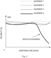
- an observation time window can be displayed in a screen.
- Fig. 8 illustrates an example of the observation time window associated with four sets of electrical equipment. As shown in the Fig. 8 , the horizontal axis represents monitoring time, the vertical axis represents a ratio indicating reliability (for example a cumulative health state) of the electrical equipment. The four curves represent four cumulative health states of four sets of electrical equipment, respectively.
- higher ratio indicates that the electrical equipment is more reliable (for example in a healthy state).
- a slight toggle of the curve indicates that the electrical equipment is in a relatively healthy state. If the trend of a curve is always at a lower level or gradually decreases from a level, the electrical equipment corresponding to this curve is in an unhealthy state over a period of time. In this way, the operators can intuitively observe the health states of different sets of electrical equipment.
- various embodiments of the present disclosure may be implemented in hardware or special purpose circuits, software, logic or any combination thereof. Some aspects may be implemented in hardware, while other aspects may be implemented in firmware or software which may be executed by a controller, microprocessor or other computing device. While various aspects of embodiments of the present disclosure are illustrated and described as block diagrams, flowcharts, or using some other pictorial representation, it will be appreciated that the blocks, apparatus, systems, techniques or methods described herein may be implemented in, as non-limiting examples, hardware, software, firmware, special purpose circuits or logic, general purpose hardware or controller or other computing devices, or some combination thereof.
- the present disclosure also provides at least one computer program product tangibly stored on a non-transitory computer readable storage medium.
- the computer program product includes computer-executable instructions, such as those included in program modules, being executed in a device on a target real or virtual processor, to carry out the process or method as described above with reference to Fig. 4 .
- program modules include routines, programs, libraries, objects, classes, components, data structures, or the like that perform particular tasks or implement particular abstract data types.
- the functionality of the program modules may be combined or split between program modules as desired in various embodiments.
- Machine-executable instructions for program modules may be executed within a local or distributed device. In a distributed device, program modules may be located in both local and remote storage media.
- Program code for carrying out methods of the present disclosure may be written in any combination of one or more programming languages. These program codes may be provided to a processor or controller of a general purpose computer, special purpose computer, or other programmable data processing apparatus, such that the program codes, when executed by the processor or controller, cause the functions/operations specified in the flowcharts and/or block diagrams to be implemented.
- the program code may execute entirely on a machine, partly on the machine, as a stand-alone software package, partly on the machine and partly on a remote machine or entirely on the remote machine or server.
- the above program code may be embodied on a machine readable medium, which may be any tangible medium that may contain, or store a program for use by or in connection with an instruction execution system, apparatus, or device.
- the machine readable medium may be a machine readable signal medium or a machine readable storage medium.
- a machine readable medium may include but not limited to an electronic, magnetic, optical, electromagnetic, infrared, or semiconductor system, apparatus, or device, or any suitable combination of the foregoing.
- machine readable storage medium More specific examples of the machine readable storage medium would include an electrical connection having one or more wires, a portable computer diskette, a hard disk, a random access memory (RAM), a read-only memory (ROM), an erasable programmable read-only memory (EPROM or Flash memory), an optical fiber, a portable compact disc read-only memory (CD-ROM), an optical storage device, a magnetic storage device, or any suitable combination of the foregoing.
- RAM random access memory
- ROM read-only memory
- EPROM or Flash memory erasable programmable read-only memory
- CD-ROM portable compact disc read-only memory
- magnetic storage device or any suitable combination of the foregoing.
Landscapes
- Physics & Mathematics (AREA)
- General Physics & Mathematics (AREA)
- Testing Relating To Insulation (AREA)
Claims (15)
- Procédé de surveillance de condition d'un équipement électrique (301) comprenant :la détection d'impulsions de décharge partielle générées dans l'équipement électrique (301) pendant au moins un cycle de puissance ;l'obtention de premières données représentant les impulsions de décharge partielle détectées pendant l'au moins un cycle de puissance ;l'obtention de deuxièmes données par résolution de phase des premières données ;l'obtention de troisièmes données par régularisation des deuxièmes données ; caractérisé par :l'analyse des troisièmes données en une première composante et au moins une deuxième composante ;l'obtention d'informations de phase de la première composante ;le décalage de la première composante et de l'au moins une deuxième composante en considérant les informations de phase obtenues ; etla génération d'un signal indiquant un état de santé de l'équipement électrique (301) en comparant les première et deuxième composantes décalées des troisièmes données avec leurs homologues associées à un équipement électrique (301) défectueux.
- Procédé selon la revendication 1, les informations de phase de la première composante comportant un angle de phase de la première composante, et le décalage de la première composante et de l'au moins une deuxième composante comprenant :
le décalage synchrone de la première composante et de l'au moins une deuxième composante pour changer l'angle de phase de la première composante à une valeur prédéterminée. - Procédé selon la revendication 1 ou 2, l'obtention des troisièmes données comprenant :
la réalisation itérative des étapes suivantes une ou plusieurs fois :la détermination d'un rapport entre un creux et une crête de grandeurs des impulsions de décharge partielle détectées, les grandeurs étant en dessous d'une valeur de référence ;si le rapport est incohérent avec un rapport cible, la diminution de la valeur de référence ; etle retrait de bruit des impulsions de décharge partielle en retirant des impulsions avec des grandeurs en dessous de la valeur de référence. - Procédé selon la revendication 1 ou 2, l'obtention des premières données comprenant :l'obtention d'une fréquence d'un réseau dans lequel l'équipement électrique fonctionne ;la génération d'un signal de synchronisation, une fréquence du signal de synchronisation étant synchronisée avec la fréquence du réseau ; etla génération des premières données en enregistrant les impulsions de décharge partielle détectées et des informations de phase du signal de synchronisation correspondant aux impulsions de décharge partielle détectées, en particulier, l'obtention de la fréquence du réseau comprenant :la réalisation d'une transformation de Fourier sur les impulsions de décharge partielle détectées ; etle calcul de la fréquence du réseau en considérant une fréquence d'une impulsion avec une grandeur maximale parmi les impulsions de décharge partielle transformées en tant que fréquence du réseau.
- Procédé selon la revendication 1 ou 2, l'obtention des deuxièmes données comprenant :la détermination, à partir des premières données, d'angles de phase des impulsions de décharge partielle ;le décalage des angles de phase des impulsions de décharge partielle dans un cycle de puissance ; etl'enregistrement des impulsions de décharge partielle et des angles de phase décalés pour obtenir les deuxièmes données.
- Procédé selon les revendications 1 ou 2, comprenant en outre :en réponse à l'indication par le signal que l'équipement électrique (301) est dans un état défectueux, l'obtention d'une ou plusieurs propriétés de l'équipement électrique (301) défectueux ; etla détermination d'une ou plusieurs propriétés de l'équipement électrique (301) sur la base des propriétés de l'équipement électrique (301) défectueux, en particulierles une ou plusieurs propriétés de l'équipement électrique comprenant : un type d'une décharge partielle générant les impulsions de décharge partielle et/ou un emplacement où une décharge partielle générant les impulsions de décharge partielle survient.
- Système (310) de surveillance de condition d'un équipement électrique (301) comprenant :une unité de traitement (311) ; etune mémoire (312) couplée à l'unité de traitement (311) et sur laquelle sont stockées des instructions, les instructions, lorsqu'elles sont exécutées par l'unité de traitement (311), amenant le système à exécuter des actions comportant :la détection d'impulsions de décharge partielle générées dans l'équipement électrique pendant au moins un cycle de puissance ;l'obtention de premières données représentant les impulsions de décharge partielle détectées pendant l'au moins un cycle de puissance ;l'obtention de deuxièmes données par résolution de phase des premières données ;l'obtention de troisièmes données par régularisation des deuxièmes données ; caractérisé par :l'analyse des troisièmes données en une première composante et au moins une deuxième composante ;l'obtention d'informations de phase de la première composante ;le décalage de la première composante et de l'au moins une deuxième composante en considérant les informations de phase obtenues ; etla génération d'un signal indiquant un état de santé de l'équipement électrique (301) en comparant les première et deuxième composantes décalées des troisièmes données avec leurs homologues associées à un équipement électrique (301) défectueux, en particulierles informations de phase de la première composante comportant un angle de phase de la première composante,et le décalage de la première composante et de l'au moins une deuxième composante comprenant :
le décalage synchrone de la première composante et de l'au moins une deuxième composante pour changer l'angle de phase de la première composante à une valeur prédéterminée. - Système selon la revendication 7, l'obtention des troisièmes données comprenant :
la réalisation itérative des étapes suivantes une ou plusieurs fois :la détermination d'un rapport entre un creux et une crête de grandeurs des impulsions de décharge partielle détectées, les grandeurs étant en dessous d'une valeur de référence ;si le rapport est incohérent avec un rapport cible, la diminution de la valeur de référence ; etle retrait de bruit des impulsions de décharge partielle en retirant des impulsions avec des grandeurs en dessous de la valeur de référence. - Système selon la revendication 7, l'obtention des premières données comprenant :l'obtention d'une fréquence d'un réseau dans lequel l'équipement électrique (301) fonctionne ;la génération d'un signal de synchronisation, une fréquence du signal de synchronisation étant synchronisée avec la fréquence du réseau ; etla génération des premières données en enregistrant les impulsions de décharge partielle détectées et des informations de phase du signal de synchronisation correspondant aux impulsions de décharge partielle détectées, en particulierl'obtention de la fréquence du réseau comprenant :la réalisation d'une transformation de Fourier sur les impulsions de décharge partielle détectées ; etle calcul de la fréquence du réseau en considérant une fréquence d'une impulsion avec une grandeur maximale parmi les impulsions de décharge partielle transformées en tant que fréquence du réseau.
- Système selon la revendication 7, l'obtention des deuxièmes données comprenant :la détermination, à partir des premières données, d'angles de phase des impulsions de décharge partielle ;le décalage des angles de phase des impulsions de décharge partielle dans un cycle de puissance ; etl'enregistrement des impulsions de décharge partielle et des angles de phase décalés pour obtenir les deuxièmes données.
- Système selon la revendication 7, les troisièmes données comportant un histogramme des deuxièmes données, l'histogramme représentant une distribution de grandeurs des impulsions de décharge partielle détectées sur des angles de phase des impulsions de décharge partielle détectées.
- Système selon la revendication 7, comprenant en outre :en réponse à l'indication par le signal que l'équipement électrique (301) est dans un état défectueux, l'obtention d'une ou plusieurs propriétés de l'équipement électrique défectueux ; etla détermination d'une ou plusieurs propriétés de l'équipement électrique (301) sur la base des propriétés de l'équipement électrique défectueux, en particulierles une ou plusieurs propriétés de l'équipement électrique comprenant : un type de décharge partielle générant les impulsions de décharge partielle et/ou un emplacement où une décharge partielle générant les impulsions de décharge partielle survient.
- Système de l'Internet des Objets (IoT) comprenant : un système de surveillance de condition d'un équipement électrique (301) selon l'une quelconque des revendications 7 à 12.
- Équipement électrique (301) comprenant le système selon l'une quelconque des revendications 7 à 12, le système étant configuré pour surveiller la condition de l'équipement électrique.
- Support lisible par ordinateur sur lequel sont stockées des instructions qui, lorsqu'elles sont exécutées sur au moins un processeur (311), amènent l'au moins un processeur à réaliser le procédé selon l'une quelconque des revendications 1 à 6.
Applications Claiming Priority (1)
| Application Number | Priority Date | Filing Date | Title |
|---|---|---|---|
| PCT/CN2018/122180 WO2020124461A1 (fr) | 2018-12-19 | 2018-12-19 | Procédé et système de surveillance de l'état d'un équipement électrique |
Publications (3)
| Publication Number | Publication Date |
|---|---|
| EP3899560A1 EP3899560A1 (fr) | 2021-10-27 |
| EP3899560A4 EP3899560A4 (fr) | 2022-07-27 |
| EP3899560B1 true EP3899560B1 (fr) | 2024-07-10 |
Family
ID=71100965
Family Applications (1)
| Application Number | Title | Priority Date | Filing Date |
|---|---|---|---|
| EP18944113.2A Active EP3899560B1 (fr) | 2018-12-19 | 2018-12-19 | Procédé et système de surveillance de l'état d'un équipement électrique |
Country Status (4)
| Country | Link |
|---|---|
| US (1) | US11300603B2 (fr) |
| EP (1) | EP3899560B1 (fr) |
| CN (1) | CN112601967B (fr) |
| WO (1) | WO2020124461A1 (fr) |
Families Citing this family (1)
| Publication number | Priority date | Publication date | Assignee | Title |
|---|---|---|---|---|
| US11899516B1 (en) | 2023-07-13 | 2024-02-13 | T-Mobile Usa, Inc. | Creation of a digital twin for auto-discovery of hierarchy in power monitoring |
Family Cites Families (29)
| Publication number | Priority date | Publication date | Assignee | Title |
|---|---|---|---|---|
| US4063033A (en) * | 1975-12-30 | 1977-12-13 | Rca Corporation | Signal quality evaluator |
| US4895121A (en) * | 1988-09-16 | 1990-01-23 | Caterpillar Inc. | Method and apparatus for measuring detonation in an internal combustion engine |
| JP3187642B2 (ja) * | 1994-02-25 | 2001-07-11 | 関西電力株式会社 | 電気機器の異常検出方法及び回転電機の異常検出装置 |
| US6088658A (en) * | 1997-04-11 | 2000-07-11 | General Electric Company | Statistical pattern analysis methods of partial discharge measurements in high voltage insulation |
| FI107083B (fi) * | 1999-10-19 | 2001-05-31 | Abb Substation Automation Oy | Menetelmä ja järjestelmä osittaispurkauksen aiheuttajan tunnistamiseksi |
| JP3854783B2 (ja) * | 2000-06-02 | 2006-12-06 | 株式会社日立製作所 | 部分放電診断装置 |
| JP4323418B2 (ja) * | 2004-12-16 | 2009-09-02 | 株式会社日本Aeパワーシステムズ | ガス絶縁機器の異常状態診断方法およびシステム |
| JP4450749B2 (ja) * | 2005-03-14 | 2010-04-14 | 中部電力株式会社 | 部分放電位置標定装置 |
| US7532012B2 (en) * | 2006-07-07 | 2009-05-12 | Ambient Corporation | Detection and monitoring of partial discharge of a power line |
| EP2321661B1 (fr) * | 2008-08-06 | 2014-03-05 | Eskom Holdings Limited | Procédé et système de surveillance de décharge partielle |
| IT1394479B1 (it) * | 2009-05-29 | 2012-07-05 | Techimp Technologies S A Ora Techimp Technologies S R L | Strumento e procedimento di rilevazione di scariche elettriche parziali in un apparato elettrico. |
| IT1396358B1 (it) * | 2009-10-30 | 2012-11-19 | Techimp Technologies S A Ora Techimp Technologies S R L | Dispositivo e procedimento per rilevare ed elaborare segnali relativi a scariche elettriche parziali. |
| US20120112772A1 (en) * | 2010-11-08 | 2012-05-10 | Huang Jui-Kun | Circuit for detecting capacitance attenuation of rectification/filter capacitor and method thereof |
| EP2466324B1 (fr) * | 2010-12-15 | 2013-07-24 | ABB Technology AG | Système combiné de mesure et de détection |
| CN102445640B (zh) | 2011-09-30 | 2014-07-02 | 云南电力试验研究院(集团)有限公司 | 基于向量机和人工鱼群优化的gis设备智能识别方法 |
| EP2802892A4 (fr) * | 2012-01-11 | 2016-03-09 | Utilx Corp | Système d'analyse et de localisation de décharges partielles |
| CN102735999B (zh) | 2012-07-02 | 2014-12-10 | 山东电力集团公司电力科学研究院 | Gis局部放电在线监测系统及其故障模式识别方法 |
| CN102841296B (zh) * | 2012-09-10 | 2015-03-04 | 江苏科技大学 | 基于超高频检测的智能开关柜局部放电在线监测系统及方法 |
| CN103543393B (zh) | 2013-10-23 | 2016-07-13 | 国家电网公司 | 一种组合电器局部放电的诊断方法及检测系统 |
| CA2928525C (fr) | 2013-10-29 | 2020-12-29 | Prysmian S.P.A. | Systeme et procede de detection de decharge partielle utilisant un signal de synchronisation synthetise |
| CN105044567B (zh) | 2015-06-29 | 2018-03-02 | 许继集团有限公司 | 一种gis局部放电在线监测模式识别方法及系统 |
| CN105137306B (zh) * | 2015-09-16 | 2018-06-26 | 杭州柯林电气股份有限公司 | 特高频局放主动噪声跟踪抑制测量系统及其工作方法 |
| CN105785236B (zh) | 2016-03-02 | 2019-02-26 | 国网江西省电力科学研究院 | 一种gis局放检测外部干扰信号排除方法 |
| CN106646169A (zh) * | 2017-01-04 | 2017-05-10 | 华北电力大学 | 一种电气设备局部放电检测数据收集云策略 |
| KR101941278B1 (ko) * | 2017-01-04 | 2019-04-12 | 한국수력원자력 주식회사 | 전력케이블의 부분방전 원인 측정 장치 및 방법 |
| WO2019182246A1 (fr) * | 2018-03-18 | 2019-09-26 | Lg Electronics Inc. | Système de détection de décharge partielle |
| EP3588110B1 (fr) * | 2018-06-29 | 2022-08-17 | ABB Schweiz AG | Système de mesure de décharge partielle |
| EP3916402B1 (fr) * | 2020-05-25 | 2024-03-20 | ABB Schweiz AG | Procédé de surveillance de l'état de l'isolation électrique d'un équipement pour systèmes électriques à moyenne ou haute tension |
| EP3933418B1 (fr) * | 2020-06-30 | 2024-06-19 | ABB Schweiz AG | Procédé de détection de décharge électrique dans un appareil électrique et système associé |
-
2018
- 2018-12-19 WO PCT/CN2018/122180 patent/WO2020124461A1/fr not_active Ceased
- 2018-12-19 EP EP18944113.2A patent/EP3899560B1/fr active Active
- 2018-12-19 CN CN201880096710.5A patent/CN112601967B/zh active Active
-
2021
- 2021-02-18 US US17/178,521 patent/US11300603B2/en active Active
Also Published As
| Publication number | Publication date |
|---|---|
| EP3899560A1 (fr) | 2021-10-27 |
| CN112601967A (zh) | 2021-04-02 |
| WO2020124461A1 (fr) | 2020-06-25 |
| US20210199707A1 (en) | 2021-07-01 |
| EP3899560A4 (fr) | 2022-07-27 |
| CN112601967B (zh) | 2024-07-30 |
| US11300603B2 (en) | 2022-04-12 |
Similar Documents
| Publication | Publication Date | Title |
|---|---|---|
| EP2579056B1 (fr) | Nouveau procédé pour analyser et diagnostiquer en temps réel les sources de décharges partielles qui se produisent dans des appareils et des installations haute tension en service ou hors service et système physique correspondant pour l'application pratique dudit procédé | |
| KR101317476B1 (ko) | 케이블 온라인 부분 방전 진단 시스템 및 방법 | |
| JP5414413B2 (ja) | ガス絶縁開閉装置の部分放電診断方法および部分放電診断装置 | |
| JP6945371B2 (ja) | 回転機システムの診断装置、電力変換装置、回転機システム、および回転機システムの診断方法 | |
| US10928436B2 (en) | Evaluation of phase-resolved partial discharge | |
| US20220018707A1 (en) | Method and Device for Monitoring a Circuit Breaker | |
| KR102244716B1 (ko) | 부분방전의 패턴분석 및 위치검출 장치 | |
| KR20210009771A (ko) | 전력 기기 부분방전 진단 시스템 및 방법 및 상기 방법을 실행시키기 위한 컴퓨터 판독 가능한 프로그램을 기록한 기록 매체 | |
| US20160109492A1 (en) | Method and system for analysing electricity consumption | |
| CN113567719A (zh) | 一种基于电流谐波和波形的窃电行为判断方法及系统 | |
| CN115993511A (zh) | 一种局部放电类型高精度检测识别装置、方法和设备 | |
| CN114675143A (zh) | 一种局部放电测量方法及装置 | |
| US11300603B2 (en) | Method and system for condition monitoring electrical equipment | |
| CN102928691A (zh) | 检测电气设备电磁瞬态骚扰信号的系统、方法及其装置 | |
| JP2018151345A (ja) | 部分放電検出方法および部分放電検出装置 | |
| JP7809594B2 (ja) | 部分放電検出方法及び部分放電検出装置 | |
| JP2019039845A (ja) | 部分放電診断装置および部分放電診断方法 | |
| CN119916147B (zh) | 局放特高频信号背景噪声的主动抑制方法及系统 | |
| CN119534976B (zh) | 变电主设备主动防御带电检测方法及装置 | |
| JP7753159B2 (ja) | 部分放電検査支援方法及び部分放電検査支援装置 | |
| KR102518013B1 (ko) | Prpd 패턴 이미지에 서포트 벡터 머신 기법을 적용한 활선 고전압 고정자 권선 부분 방전 유형 판별 방법 | |
| JP2006084413A (ja) | 電磁波妨害信号の発生源特定方法 | |
| JP2020101491A (ja) | 部分放電検出装置および部分放電検出方法 | |
| CN120214389B (zh) | 一种配变终端的电压闪变监测方法、设备及存储介质 | |
| KR102948533B1 (ko) | 부분방전 패턴 이중화 측정기술과 유사도 분석 기법이 적용된 수배전반(고압반, 저압반, 전동기제어반, 분전반) |
Legal Events
| Date | Code | Title | Description |
|---|---|---|---|
| STAA | Information on the status of an ep patent application or granted ep patent |
Free format text: STATUS: THE INTERNATIONAL PUBLICATION HAS BEEN MADE |
|
| PUAI | Public reference made under article 153(3) epc to a published international application that has entered the european phase |
Free format text: ORIGINAL CODE: 0009012 |
|
| STAA | Information on the status of an ep patent application or granted ep patent |
Free format text: STATUS: REQUEST FOR EXAMINATION WAS MADE |
|
| 17P | Request for examination filed |
Effective date: 20210210 |
|
| AK | Designated contracting states |
Kind code of ref document: A1 Designated state(s): AL AT BE BG CH CY CZ DE DK EE ES FI FR GB GR HR HU IE IS IT LI LT LU LV MC MK MT NL NO PL PT RO RS SE SI SK SM TR |
|
| DAV | Request for validation of the european patent (deleted) | ||
| DAX | Request for extension of the european patent (deleted) | ||
| A4 | Supplementary search report drawn up and despatched |
Effective date: 20220624 |
|
| RIC1 | Information provided on ipc code assigned before grant |
Ipc: G01R 31/12 20200101AFI20220620BHEP |
|
| GRAP | Despatch of communication of intention to grant a patent |
Free format text: ORIGINAL CODE: EPIDOSNIGR1 |
|
| STAA | Information on the status of an ep patent application or granted ep patent |
Free format text: STATUS: GRANT OF PATENT IS INTENDED |
|
| INTG | Intention to grant announced |
Effective date: 20240312 |
|
| GRAS | Grant fee paid |
Free format text: ORIGINAL CODE: EPIDOSNIGR3 |
|
| GRAA | (expected) grant |
Free format text: ORIGINAL CODE: 0009210 |
|
| STAA | Information on the status of an ep patent application or granted ep patent |
Free format text: STATUS: THE PATENT HAS BEEN GRANTED |
|
| AK | Designated contracting states |
Kind code of ref document: B1 Designated state(s): AL AT BE BG CH CY CZ DE DK EE ES FI FR GB GR HR HU IE IS IT LI LT LU LV MC MK MT NL NO PL PT RO RS SE SI SK SM TR |
|
| REG | Reference to a national code |
Ref country code: CH Ref legal event code: EP |
|
| REG | Reference to a national code |
Ref country code: DE Ref legal event code: R096 Ref document number: 602018071744 Country of ref document: DE |
|
| REG | Reference to a national code |
Ref country code: LT Ref legal event code: MG9D |
|
| REG | Reference to a national code |
Ref country code: NL Ref legal event code: MP Effective date: 20240710 |
|
| PG25 | Lapsed in a contracting state [announced via postgrant information from national office to epo] |
Ref country code: PT Free format text: LAPSE BECAUSE OF FAILURE TO SUBMIT A TRANSLATION OF THE DESCRIPTION OR TO PAY THE FEE WITHIN THE PRESCRIBED TIME-LIMIT Effective date: 20241111 |
|
| REG | Reference to a national code |
Ref country code: AT Ref legal event code: MK05 Ref document number: 1702489 Country of ref document: AT Kind code of ref document: T Effective date: 20240710 |
|
| PG25 | Lapsed in a contracting state [announced via postgrant information from national office to epo] |
Ref country code: NL Free format text: LAPSE BECAUSE OF FAILURE TO SUBMIT A TRANSLATION OF THE DESCRIPTION OR TO PAY THE FEE WITHIN THE PRESCRIBED TIME-LIMIT Effective date: 20240710 |
|
| PG25 | Lapsed in a contracting state [announced via postgrant information from national office to epo] |
Ref country code: PT Free format text: LAPSE BECAUSE OF FAILURE TO SUBMIT A TRANSLATION OF THE DESCRIPTION OR TO PAY THE FEE WITHIN THE PRESCRIBED TIME-LIMIT Effective date: 20241111 Ref country code: NL Free format text: LAPSE BECAUSE OF FAILURE TO SUBMIT A TRANSLATION OF THE DESCRIPTION OR TO PAY THE FEE WITHIN THE PRESCRIBED TIME-LIMIT Effective date: 20240710 |
|
| PG25 | Lapsed in a contracting state [announced via postgrant information from national office to epo] |
Ref country code: NO Free format text: LAPSE BECAUSE OF FAILURE TO SUBMIT A TRANSLATION OF THE DESCRIPTION OR TO PAY THE FEE WITHIN THE PRESCRIBED TIME-LIMIT Effective date: 20241010 |
|
| PG25 | Lapsed in a contracting state [announced via postgrant information from national office to epo] |
Ref country code: FI Free format text: LAPSE BECAUSE OF FAILURE TO SUBMIT A TRANSLATION OF THE DESCRIPTION OR TO PAY THE FEE WITHIN THE PRESCRIBED TIME-LIMIT Effective date: 20240710 Ref country code: PL Free format text: LAPSE BECAUSE OF FAILURE TO SUBMIT A TRANSLATION OF THE DESCRIPTION OR TO PAY THE FEE WITHIN THE PRESCRIBED TIME-LIMIT Effective date: 20240710 Ref country code: GR Free format text: LAPSE BECAUSE OF FAILURE TO SUBMIT A TRANSLATION OF THE DESCRIPTION OR TO PAY THE FEE WITHIN THE PRESCRIBED TIME-LIMIT Effective date: 20241011 |
|
| PG25 | Lapsed in a contracting state [announced via postgrant information from national office to epo] |
Ref country code: BG Free format text: LAPSE BECAUSE OF FAILURE TO SUBMIT A TRANSLATION OF THE DESCRIPTION OR TO PAY THE FEE WITHIN THE PRESCRIBED TIME-LIMIT Effective date: 20240710 |
|
| PG25 | Lapsed in a contracting state [announced via postgrant information from national office to epo] |
Ref country code: LV Free format text: LAPSE BECAUSE OF FAILURE TO SUBMIT A TRANSLATION OF THE DESCRIPTION OR TO PAY THE FEE WITHIN THE PRESCRIBED TIME-LIMIT Effective date: 20240710 |
|
| PG25 | Lapsed in a contracting state [announced via postgrant information from national office to epo] |
Ref country code: AT Free format text: LAPSE BECAUSE OF FAILURE TO SUBMIT A TRANSLATION OF THE DESCRIPTION OR TO PAY THE FEE WITHIN THE PRESCRIBED TIME-LIMIT Effective date: 20240710 Ref country code: IS Free format text: LAPSE BECAUSE OF FAILURE TO SUBMIT A TRANSLATION OF THE DESCRIPTION OR TO PAY THE FEE WITHIN THE PRESCRIBED TIME-LIMIT Effective date: 20241110 |
|
| PG25 | Lapsed in a contracting state [announced via postgrant information from national office to epo] |
Ref country code: HR Free format text: LAPSE BECAUSE OF FAILURE TO SUBMIT A TRANSLATION OF THE DESCRIPTION OR TO PAY THE FEE WITHIN THE PRESCRIBED TIME-LIMIT Effective date: 20240710 |
|
| PG25 | Lapsed in a contracting state [announced via postgrant information from national office to epo] |
Ref country code: ES Free format text: LAPSE BECAUSE OF FAILURE TO SUBMIT A TRANSLATION OF THE DESCRIPTION OR TO PAY THE FEE WITHIN THE PRESCRIBED TIME-LIMIT Effective date: 20240710 Ref country code: RS Free format text: LAPSE BECAUSE OF FAILURE TO SUBMIT A TRANSLATION OF THE DESCRIPTION OR TO PAY THE FEE WITHIN THE PRESCRIBED TIME-LIMIT Effective date: 20241010 |
|
| PG25 | Lapsed in a contracting state [announced via postgrant information from national office to epo] |
Ref country code: RS Free format text: LAPSE BECAUSE OF FAILURE TO SUBMIT A TRANSLATION OF THE DESCRIPTION OR TO PAY THE FEE WITHIN THE PRESCRIBED TIME-LIMIT Effective date: 20241010 Ref country code: PL Free format text: LAPSE BECAUSE OF FAILURE TO SUBMIT A TRANSLATION OF THE DESCRIPTION OR TO PAY THE FEE WITHIN THE PRESCRIBED TIME-LIMIT Effective date: 20240710 Ref country code: NO Free format text: LAPSE BECAUSE OF FAILURE TO SUBMIT A TRANSLATION OF THE DESCRIPTION OR TO PAY THE FEE WITHIN THE PRESCRIBED TIME-LIMIT Effective date: 20241010 Ref country code: LV Free format text: LAPSE BECAUSE OF FAILURE TO SUBMIT A TRANSLATION OF THE DESCRIPTION OR TO PAY THE FEE WITHIN THE PRESCRIBED TIME-LIMIT Effective date: 20240710 Ref country code: IS Free format text: LAPSE BECAUSE OF FAILURE TO SUBMIT A TRANSLATION OF THE DESCRIPTION OR TO PAY THE FEE WITHIN THE PRESCRIBED TIME-LIMIT Effective date: 20241110 Ref country code: HR Free format text: LAPSE BECAUSE OF FAILURE TO SUBMIT A TRANSLATION OF THE DESCRIPTION OR TO PAY THE FEE WITHIN THE PRESCRIBED TIME-LIMIT Effective date: 20240710 Ref country code: GR Free format text: LAPSE BECAUSE OF FAILURE TO SUBMIT A TRANSLATION OF THE DESCRIPTION OR TO PAY THE FEE WITHIN THE PRESCRIBED TIME-LIMIT Effective date: 20241011 Ref country code: FI Free format text: LAPSE BECAUSE OF FAILURE TO SUBMIT A TRANSLATION OF THE DESCRIPTION OR TO PAY THE FEE WITHIN THE PRESCRIBED TIME-LIMIT Effective date: 20240710 Ref country code: ES Free format text: LAPSE BECAUSE OF FAILURE TO SUBMIT A TRANSLATION OF THE DESCRIPTION OR TO PAY THE FEE WITHIN THE PRESCRIBED TIME-LIMIT Effective date: 20240710 Ref country code: BG Free format text: LAPSE BECAUSE OF FAILURE TO SUBMIT A TRANSLATION OF THE DESCRIPTION OR TO PAY THE FEE WITHIN THE PRESCRIBED TIME-LIMIT Effective date: 20240710 Ref country code: AT Free format text: LAPSE BECAUSE OF FAILURE TO SUBMIT A TRANSLATION OF THE DESCRIPTION OR TO PAY THE FEE WITHIN THE PRESCRIBED TIME-LIMIT Effective date: 20240710 |
|
| REG | Reference to a national code |
Ref country code: DE Ref legal event code: R097 Ref document number: 602018071744 Country of ref document: DE |
|
| PG25 | Lapsed in a contracting state [announced via postgrant information from national office to epo] |
Ref country code: RO Free format text: LAPSE BECAUSE OF FAILURE TO SUBMIT A TRANSLATION OF THE DESCRIPTION OR TO PAY THE FEE WITHIN THE PRESCRIBED TIME-LIMIT Effective date: 20240710 Ref country code: DK Free format text: LAPSE BECAUSE OF FAILURE TO SUBMIT A TRANSLATION OF THE DESCRIPTION OR TO PAY THE FEE WITHIN THE PRESCRIBED TIME-LIMIT Effective date: 20240710 Ref country code: SM Free format text: LAPSE BECAUSE OF FAILURE TO SUBMIT A TRANSLATION OF THE DESCRIPTION OR TO PAY THE FEE WITHIN THE PRESCRIBED TIME-LIMIT Effective date: 20240710 |
|
| PG25 | Lapsed in a contracting state [announced via postgrant information from national office to epo] |
Ref country code: EE Free format text: LAPSE BECAUSE OF FAILURE TO SUBMIT A TRANSLATION OF THE DESCRIPTION OR TO PAY THE FEE WITHIN THE PRESCRIBED TIME-LIMIT Effective date: 20240710 |
|
| PG25 | Lapsed in a contracting state [announced via postgrant information from national office to epo] |
Ref country code: CZ Free format text: LAPSE BECAUSE OF FAILURE TO SUBMIT A TRANSLATION OF THE DESCRIPTION OR TO PAY THE FEE WITHIN THE PRESCRIBED TIME-LIMIT Effective date: 20240710 |
|
| PG25 | Lapsed in a contracting state [announced via postgrant information from national office to epo] |
Ref country code: SK Free format text: LAPSE BECAUSE OF FAILURE TO SUBMIT A TRANSLATION OF THE DESCRIPTION OR TO PAY THE FEE WITHIN THE PRESCRIBED TIME-LIMIT Effective date: 20240710 |
|
| PLBE | No opposition filed within time limit |
Free format text: ORIGINAL CODE: 0009261 |
|
| STAA | Information on the status of an ep patent application or granted ep patent |
Free format text: STATUS: NO OPPOSITION FILED WITHIN TIME LIMIT |
|
| 26N | No opposition filed |
Effective date: 20250411 |
|
| PG25 | Lapsed in a contracting state [announced via postgrant information from national office to epo] |
Ref country code: MC Free format text: LAPSE BECAUSE OF FAILURE TO SUBMIT A TRANSLATION OF THE DESCRIPTION OR TO PAY THE FEE WITHIN THE PRESCRIBED TIME-LIMIT Effective date: 20240710 |
|
| REG | Reference to a national code |
Ref country code: CH Ref legal event code: PL |
|
| PG25 | Lapsed in a contracting state [announced via postgrant information from national office to epo] |
Ref country code: LU Free format text: LAPSE BECAUSE OF NON-PAYMENT OF DUE FEES Effective date: 20241219 |
|
| GBPC | Gb: european patent ceased through non-payment of renewal fee |
Effective date: 20241219 |
|
| PG25 | Lapsed in a contracting state [announced via postgrant information from national office to epo] |
Ref country code: SE Free format text: LAPSE BECAUSE OF FAILURE TO SUBMIT A TRANSLATION OF THE DESCRIPTION OR TO PAY THE FEE WITHIN THE PRESCRIBED TIME-LIMIT Effective date: 20240710 |
|
| REG | Reference to a national code |
Ref country code: BE Ref legal event code: MM Effective date: 20241231 |
|
| PG25 | Lapsed in a contracting state [announced via postgrant information from national office to epo] |
Ref country code: GB Free format text: LAPSE BECAUSE OF NON-PAYMENT OF DUE FEES Effective date: 20241219 Ref country code: BE Free format text: LAPSE BECAUSE OF NON-PAYMENT OF DUE FEES Effective date: 20241231 |
|
| PG25 | Lapsed in a contracting state [announced via postgrant information from national office to epo] |
Ref country code: CH Free format text: LAPSE BECAUSE OF NON-PAYMENT OF DUE FEES Effective date: 20241231 |
|
| PG25 | Lapsed in a contracting state [announced via postgrant information from national office to epo] |
Ref country code: IE Free format text: LAPSE BECAUSE OF NON-PAYMENT OF DUE FEES Effective date: 20241219 |
|
| PGFP | Annual fee paid to national office [announced via postgrant information from national office to epo] |
Ref country code: DE Payment date: 20251211 Year of fee payment: 8 |
|
| PGFP | Annual fee paid to national office [announced via postgrant information from national office to epo] |
Ref country code: IT Payment date: 20251223 Year of fee payment: 8 |
|
| PGFP | Annual fee paid to national office [announced via postgrant information from national office to epo] |
Ref country code: FR Payment date: 20251229 Year of fee payment: 8 |