EP3899997B1 - Commutateur électrique et système de commutateur électrique - Google Patents
Commutateur électrique et système de commutateur électrique Download PDFInfo
- Publication number
- EP3899997B1 EP3899997B1 EP19831864.4A EP19831864A EP3899997B1 EP 3899997 B1 EP3899997 B1 EP 3899997B1 EP 19831864 A EP19831864 A EP 19831864A EP 3899997 B1 EP3899997 B1 EP 3899997B1
- Authority
- EP
- European Patent Office
- Prior art keywords
- wheel
- electrical switch
- switch
- contact
- arm
- Prior art date
- Legal status (The legal status is an assumption and is not a legal conclusion. Google has not performed a legal analysis and makes no representation as to the accuracy of the status listed.)
- Active
Links
Images




Classifications
-
- H—ELECTRICITY
- H01—ELECTRIC ELEMENTS
- H01H—ELECTRIC SWITCHES; RELAYS; SELECTORS; EMERGENCY PROTECTIVE DEVICES
- H01H1/00—Contacts
- H01H1/12—Contacts characterised by the manner in which co-operating contacts engage
- H01H1/14—Contacts characterised by the manner in which co-operating contacts engage by abutting
- H01H1/16—Contacts characterised by the manner in which co-operating contacts engage by abutting by rolling; by wrapping; Roller or ball contacts
-
- H—ELECTRICITY
- H01—ELECTRIC ELEMENTS
- H01H—ELECTRIC SWITCHES; RELAYS; SELECTORS; EMERGENCY PROTECTIVE DEVICES
- H01H1/00—Contacts
- H01H1/12—Contacts characterised by the manner in which co-operating contacts engage
- H01H1/36—Contacts characterised by the manner in which co-operating contacts engage by sliding
- H01H1/42—Knife-and-clip contacts
-
- H—ELECTRICITY
- H01—ELECTRIC ELEMENTS
- H01H—ELECTRIC SWITCHES; RELAYS; SELECTORS; EMERGENCY PROTECTIVE DEVICES
- H01H33/00—High-tension or heavy-current switches with arc-extinguishing or arc-preventing means
- H01H33/02—Details
- H01H33/04—Means for extinguishing or preventing arc between current-carrying parts
- H01H33/20—Means for extinguishing or preventing arc between current-carrying parts using arcing horns
-
- H—ELECTRICITY
- H01—ELECTRIC ELEMENTS
- H01H—ELECTRIC SWITCHES; RELAYS; SELECTORS; EMERGENCY PROTECTIVE DEVICES
- H01H33/00—High-tension or heavy-current switches with arc-extinguishing or arc-preventing means
- H01H33/02—Details
- H01H33/28—Power arrangements internal to the switch for operating the driving mechanism
- H01H33/285—Power arrangements internal to the switch for operating the driving mechanism using electro-dynamic repulsion
-
- H—ELECTRICITY
- H01—ELECTRIC ELEMENTS
- H01H—ELECTRIC SWITCHES; RELAYS; SELECTORS; EMERGENCY PROTECTIVE DEVICES
- H01H9/00—Details of switching devices, not covered by groups H01H1/00 - H01H7/00
- H01H9/30—Means for extinguishing or preventing arc between current-carrying parts
- H01H9/38—Auxiliary contacts on to which the arc is transferred from the main contacts
-
- H—ELECTRICITY
- H01—ELECTRIC ELEMENTS
- H01H—ELECTRIC SWITCHES; RELAYS; SELECTORS; EMERGENCY PROTECTIVE DEVICES
- H01H9/00—Details of switching devices, not covered by groups H01H1/00 - H01H7/00
- H01H9/30—Means for extinguishing or preventing arc between current-carrying parts
- H01H9/46—Means for extinguishing or preventing arc between current-carrying parts using arcing horns
Definitions
- the present invention relates to an electrical switch. More particularly, but not exclusively, the present invention relates to an electrical switch comprising first and second arms, the second arm comprising a wheel, the switch being adapted such that as the switch closes an arcing portion of the first arm contacts the wheel before a main portion of the first arm contacts a body portion of the second arm.
- the present invention also relates to an electrical switch system. More particularly, but not exclusively, the present invention relates to an electrical switch system comprising an electrical switch, one arm of the electrical switch being connected to a power supply, the other arm being connected to a load.
- DE6811150U discloses a coaxial two-way switch with a rotatable contact device which can be moved into at least two switching positions, in particular via a magnetic drive, and which is designed as an insulating disc with strip conductors applied on both sides, with which fork contacts which are connected to the inner conductor of the relevant coaxial conductor section interact.
- FR2891395 discloses a disconnection module for electrical apparatus e.g. circuit-breaker, which has two pairs of mobile contacts coupled by a rotation driving mechanism that is arranged for inversing rotation of one pair with respect to other pair.
- Document EP1961 027 discloses a high voltage circuit breaker having fixed contacts on a carrier and movable contacts that move on shaft.
- the fixed contacts have a have permanent magnets that operate to extinguish any arcing between the contacts.
- the current invention seeks to overcome the problems of the prior art.
- the present invention provides a electrical switch according to claim 1.
- the switch according to the invention therefore has a considerably longer lifespan than known switches.
- the main portion comprises at least one pair of spaced apart main portion fingers, the body portion being adapted to be received between the main portion fingers.
- the electrical switch further comprises at least one electrically conductive contact washer having a central aperture, the contact washer being arranged on a face of the wheel.
- the wheel is sandwiched between contact washers.
- the contact washer comprises a plurality of spaced apart first slots extending from the central aperture part way to the outer edge of the washer.
- the contact washer comprises a plurality of spaced apart second slots extending from the outer edge of the washer part way to the central aperture.
- the first slots are interdigitated with the second slots.
- an electrical switch system comprising
- the electrical switch system further comprises a load connected to the other arm.
- the load is an electric vehicle.
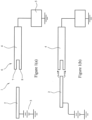
- FIG 1(a) Shown in figure 1(a) in schematic form is a known switch 1 for use in a high current application.
- the switch 1 comprises a first electrically conductive arm 2 connected to a voltage source 3. It further comprises a second electrically conductive arm 4 connected to a load 5, which in this application is an electric train.
- the second arm 4 ends in a connector 6 which comprises first and second spaced apart fingers 7,8.
- the two arms 2,4 are spaced apart and the switch 1 is in the open configuration.
- the first arm 2 In order to switch the switch 1 to the closed configuration the first arm 2 is moved towards the second arm 4 as shown in figure 1(b) . As the first arm 2 approaches the second arm 4 pre contact arcing occurs as shown and current starts to flow from the first arm 2 to the second arm 4.
- the switch comprises a first electrically conductive arm 11 which comprises an electrically conductive arcing portion 12 and an electrically conductive main portion 13.
- the arcing portion 12 comprises first and second spaced apart arcing fingers 14 pivotally connected to a base portion 15 by an arcing finger pivot 16.
- the main portion 13 comprises a plurality of pairs of main portion fingers 17, each pair of main portion fingers 17 being pivotally connected to the base portion 15 by a base portion pivot 18.
- the base portion 15 is shown connected to a load 19 which is in turn connected to earth 20.
- the electrical switch 10 further comprises a second electrically conductive arm 21.
- the second electrically conductive arm 21 comprises an electrically conductive body portion 22.
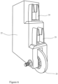
- the second arm 21 further comprises an electrically conductive wheel 23 which is connected to the body portion 22 by a wheel axle 24 which extends along a wheel axis. The wheel 23 is free to rotate about the wheel axis.
- the end of the second arm 21 proximate to the first arm 11 is shown in greater detail in figure 3 .
- the body portion 22 comprises a plurality of electrically conductive receiving fingers 25.
- Each receiving finger 25 terminates in an electrically taper 26.
- the taper 26 may be electrically insulating.
- the electrically conductive wheel 23 is sandwiched between contact washers 27.
- the contact washers 27 abut the body portion 22 ensuring a good electrical contact between the wheel 23 and the body portion 22.
- the contact washer 27 is cylindrical and arranged around the wheel axle 24.
- the wheel 23 is arranged around the contact washer 27.
- the contact washer 27 comprises an electrically conductive, preferably copper, disk defined by an outer edge 28. Extending through the center of the disk is a central aperture 29. A plurality of spaced apart first slots 30 extend from the central aperture 29 part way to the outer edge 28. A plurality of spaced apart second slots 31 extend from the outer edge 28 part way to the central aperture 29. The first slots 30 and second slots 31 are interdigitated. As can be seen in side view, the center of the washer 27 is slightly raised with respect to the outer edge 28 so that the washer 27 is slightly bowl shaped and matches the profile of the wheel 23.
- each contact washer 27 is centered on a face of the wheel 23 with the center of the central aperture 29 coaxial with the wheel axle 24.
- the switch 10 is shown in the open configuration with the first and second arms 11,21 spaced apart.
- the switch 10 further comprises a pivot mechanism 32 connected to each of the pairs of arcing fingers 14 and main potion fingers 17.
- the pivot mechanism 32 simultaneously pivots the pair of arcing fingers 14 and multiple pairs of main portion fingers 17 towards the second electrically conductive arm 21.
- the arcing fingers 14 approach the wheel 23 pre-contact arcing occurs between the arcing fingers 14 and wheel 23.
- the edge of the wheel 23 is received between the arcing fingers 14.
- the wheel 23 rotates around the wheel axis, so allowing pivoting to continue with little resistance.
- each pair of main portion fingers 17 slides onto a taper 26 and then onto a receiving finger 25.
- a significant portion of the current is flowing through the arcing fingers 14 and wheel 23.
- the remainder of the current is divided between each of the pairs of main portion fingers 17.
- the current flowing through a single pair of main portion fingers 17 to its associated receiving finger 25 is therefore relatively small and so the Lorentz force between the main portion fingers 17 and the receiving finger 25 is also small.
- the pivot mechanism 32 can therefore pull the main portion fingers 17 onto the receiving fingers 25 with relatively little force, so closing the switch 10.
- the switch 10 is designed such that the main portion fingers 17 slide onto the receiving fingers 25 shortly after the arcing fingers 14 engage the wheel 23.
- the time difference is of the order a few milliseconds so as to avoid overheating the arcing fingers 14 and contact washers 27.
- the switch 10 according to the invention can therefore be switched from the open configuration to the closed configuration (and vice versa) with relatively little force.
- the switch 10 is shown in the closed configuration in figure 5 .
- a further advantage of the switch 10 according to the invention is that the wheel 23 is not necessarily in the same orientation with respect to the remainder of the second arm 21 each time the switch 10 is opened or closed. The erosion of the wheel 23 caused by pre contact arcing is therefore spread around the periphery of the wheel 23 rather than concentrated at one spot.
- FIG. 6 Shown in figure 6 is the end of the second arm 21 of an alternative embodiment of the invention.
- the body portion 22 comprises a plurality of pairs of receiving fingers 25.
- the main portion 13 of the first arm 11 comprises a plurality of single main portion fingers 17 each pivotally connected to the base portion 15.
- the operation of this second embodiment is similar to that of the first embodiment only with the main portion fingers 17 being received between pairs of receiving fingers 25 rather than vice versa.
- the electrical switch 10 comprises a first electrically conductive arm 11.
- the first arm 11 comprises an electrically conductive arcing portion 12 and an electrically conductive main portion 13.
- the arcing portion 12 comprises a resiliently deformable rail 33 having a slot 34 running along its length.
- the rail 33 is connected to a base portion 15.
- the main portion 13 comprises a plurality of main portion fingers 17 fixedly extending from the base portion 15.
- the switch 10 further comprises a second electrically conductive arm 21.
- the second arm 21 comprises a body portion 22. Connected to the body portion 22 by a wheel axle 24 which extends along a wheel axis is an electrically conductive wheel 23. The wheel 23 is free to rotate about the wheel axle 24.
- the body portion 22 comprises a plurality of receiving fingers 25 extending towards the first electrically conductive arm 11.
- the switch 10 further comprises a displacement mechanism 35 connected to the first arm 11.
- the displacement mechanism 35 is adapted to linearly displace the first arm 11 towards and away from the second arm 21.
- the switch 10 is shown in the open configuration with the first and second arms 11,21 spaced apart.
- the displacement mechanism 35 displaces the first arm 11 towards the second arm 21 until the wheel 23 engages the slot 34 running along the length of the rail 33.
- the switch 10 can be switched between open and closed configurations with relatively little force so making the switch 10 reliable and inexpensive to manufacture.
- the electrical switch system 40 comprises an electrical switch 10 as previously described.
- a power supply 41 Connected to one arm 11,21 is a power supply 41.
- the power supply 41 can provide a high current, typically in the range 50,000 to 200,000 Amps, more preferably in the range 80,000 - 150,000 Amps. More preferably the current is in the range 100,000 to 140,000 Amps.
- the other arm 11,21 of the switch 10 is connected to a load 42 which is in turn connected to earth 43.
- the load 42 is typically an electrically powered vehicle such as a train but the invention is not so limited.
- the switch 10 comprises a plurality of pairs of main portion fingers 17. In an alternative embodiment the switch 10 comprises a single pair of main portion fingers 17.
- the switch 10 can be employed in both AC and DC systems.
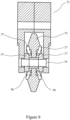
- FIG. 9 Shown in figure 9 in vertical cross section is a second arm 21 of a further embodiment of an electrical switch10 according to the invention.
- the electrically conductive wheel 23 is arranged on a wheel axle 24 which in turn is connected to the body portion 22.
- the wheel 23 has a recess 36 in each face proximate to the wheel axle 24.
- the electrical switch 10 further comprises a pair of electrically conductive axle collars 37 arranged around the wheel axle 24.
- the contact washers 27 are initially flat. As the wheel 23, wheel axle 24 and axle collars 37 are assembled the axle collars 37 deform the contact washers 27 into the desired shape.
Landscapes
- Arc-Extinguishing Devices That Are Switches (AREA)
- Rotary Switch, Piano Key Switch, And Lever Switch (AREA)
Claims (10)
- Commutateur électrique (10) comprenant un premier bras à conduction électrique (11) comprenant :une première partie à conduction électrique en forme d'arc (12) et une partie principale à conduction électrique (13) ;un deuxième bras à conduction électrique (21) comprenant une partie formant corps à conduction électrique (22) ;au moins l'un parmi le premier bras et le deuxième bras (11, 21) étant configuré pour un déplacement par rapport à l'autre afin de faire déplacer le commutateur (10) entre une configuration ouverte, dans laquelle les premier et deuxième bras (11, 21) sont espacés l'un de l'autre, et une configuration fermée, dans laquelle la partie principale (13) est au contact de la partie principale (22) ;le commutateur électrique (10) comprenant en outre un mécanisme à pivot (32) pour faire pivoter la partie en forme d'arc (12) et la partie principale (13) au contact de la partie formant corps (22),caractérisé en ce que :le deuxième bras à conduction électrique (21) comprend en outre une roue à conduction électrique (23) connectée à la partie formant corps (22) par un essieu de roue (24), qui s'étend le long d'un axe de roue, la roue (23) étant libre de tourner autour de l'axe de la roue, la roue (23) se trouvant en contact électrique avec la partie formant corps (22), selon lequel, dans la configuration fermée la partie en forme d'arc (12) est en contact avec la roue (23), le commutateur (10) étant configuré de sorte que pendant la commutation du commutateur (10) de la configuration ouverte à la configuration fermée, la partie en forme d'arc (12) vient au contact de la roue (23) avant que la partie principale (13) ne vienne au contact de la partie formant corps (22) ;selon lequel la partie en forme d'arc (12) comprend au moins une paire de doigts d'arc espacés l'un de l'autre (14), la roue (23) étant configuré pour être reçue entre les doigts (14), et en ce que le mécanisme de pivot (32) est configuré pour faire pivoter la partie en forme d'arc (21) pour venir au contact de la roue (23).
- Commutateur électrique (10) selon la revendication 1, selon lequel la partie principale (13) comprend au moins une paire de doigts de partie principale espacés l'un de l'autre (17), la partie formant corps (22) étant configuré pour être reçue entre les doigts de la partie principale (17).
- Commutateur électrique (10) selon l'une quelconque des revendications 1 ou 2, comprenant au moins une rondelle de contact à conduction électrique (27) présentant une ouverture centrale (29), la rondelle de contact (27) étant disposée sur une face de la roue (23).
- Commutateur électrique (10) selon la revendication 3, selon lequel la roue (23) est prise en sandwich entre des rondelles de contact (27).
- Commutateur électrique (10) selon la revendication 3 ou la revendication 4, selon lequel la rondelle de contact (27) comprend une pluralité de premières fentes espacées les unes des autres (30) s'étendant depuis l'ouverture centrale (29) partiellement en direction du bord extérieur (28) de la rondelle (27).
- Commutateur électrique (10) selon l'une quelconque des revendications 3 à 5, selon lequel la rondelle de contact (27) comprend une pluralité de deuxièmes fentes espacées les unes des autres (31) s'étendant depuis le bord extérieur (28) de la rondelle (27) partiellement en direction de l'ouverture centrale (29).
- Commutateur électrique (10) selon la revendication 6 lorsqu'elle dépend de la revendication 5, selon lequel les premières fentes (30) s'intercalent avec les deuxièmes fentes (31).
- Système de commutateur électrique (40) comprenant :un commutateur électrique (10) selon l'une quelconque des revendications 1 à 7 ; et,une alimentation électrique (41) connectée à l'un parmi les premier et deuxième bras (11, 21).
- Système de commutateur électrique (40) selon la revendication 8, comprenant en outre une charge (19, 42) connectée à l'autre bras (21, 11).
- Système de commutateur électrique (40) selon la revendication 9, selon lequel la charge (19) est un véhicule électrique.
Applications Claiming Priority (2)
| Application Number | Priority Date | Filing Date | Title |
|---|---|---|---|
| GB1821167.2A GB2580174B (en) | 2018-12-23 | 2018-12-23 | An electrical switch and an electrical switch system |
| PCT/GB2019/053687 WO2020136372A1 (fr) | 2018-12-23 | 2019-12-23 | Commutateur électrique et système de commutateur électrique |
Publications (2)
| Publication Number | Publication Date |
|---|---|
| EP3899997A1 EP3899997A1 (fr) | 2021-10-27 |
| EP3899997B1 true EP3899997B1 (fr) | 2024-10-30 |
Family
ID=65364430
Family Applications (1)
| Application Number | Title | Priority Date | Filing Date |
|---|---|---|---|
| EP19831864.4A Active EP3899997B1 (fr) | 2018-12-23 | 2019-12-23 | Commutateur électrique et système de commutateur électrique |
Country Status (4)
| Country | Link |
|---|---|
| EP (1) | EP3899997B1 (fr) |
| CN (1) | CN113454741B (fr) |
| GB (1) | GB2580174B (fr) |
| WO (1) | WO2020136372A1 (fr) |
Citations (1)
| Publication number | Priority date | Publication date | Assignee | Title |
|---|---|---|---|---|
| EP1961027B1 (fr) * | 2005-12-13 | 2013-11-13 | Siemens Aktiengesellschaft | Sectionneur de charge pour poste de commutation blinde, et systeme d'aimant permanent pour sectionneur de charge |
Family Cites Families (12)
| Publication number | Priority date | Publication date | Assignee | Title |
|---|---|---|---|---|
| GB479315A (en) * | 1936-12-31 | 1938-02-03 | William Train Gray | Improvements relating to electric controllers |
| DE1181803B (de) * | 1959-06-29 | 1964-11-19 | Licentia Gmbh | Verbindungsumsteller fuer Transformatoren |
| DE6811150U (de) * | 1968-12-12 | 1969-08-14 | Spinner Gmbh Elektrotech | Koaxialer zweiwegeschalter |
| CH498548A (de) * | 1969-10-31 | 1970-10-31 | Contraves Ag | Platte mit gedruckten Leiterbahnen für einen Schalter |
| EP0010112A1 (fr) * | 1978-10-17 | 1980-04-30 | ATELIERS DE CONSTRUCTIONS ELECTRIQUES DE CHARLEROI (ACEC) Société Anonyme | Appareillage électrique tel qu'un commutateur, avec des contacts disposés autour de l'axe d'une came rotative |
| CN2360920Y (zh) * | 1998-07-16 | 2000-01-26 | 张韬 | 滚动抽插式触头机构 |
| FR2852443B1 (fr) * | 2003-03-11 | 2009-12-04 | Dav | Dispositif de commutation a commande par molette et sa mise en oeuvre dans un circuit de commande d'affichage |
| FR2891395B1 (fr) * | 2005-09-28 | 2007-11-30 | Socomec Sa Sa | Module de coupure pour appareil electrique et appareil electrique equipe d'un tel module |
| DE102011118418B4 (de) * | 2011-11-12 | 2015-07-16 | Ellenberger & Poensgen Gmbh | Schaltsystem |
| CN102403161B (zh) * | 2012-01-12 | 2014-05-14 | 沈阳华德海泰电器有限公司 | 一种具有开断母线转移电流能力的三工位开关 |
| CN103871758A (zh) * | 2012-12-12 | 2014-06-18 | 施耐德电器工业公司 | 用于中高压断路器或开关的旋转触头 |
| DE102013002155A1 (de) * | 2012-12-15 | 2014-07-03 | Brose Fahrzeugteile GmbH & Co. Kommanditgesellschaft, Würzburg | Elektromotor mit Thermosicherung |
-
2018
- 2018-12-23 GB GB1821167.2A patent/GB2580174B/en active Active
-
2019
- 2019-12-23 CN CN201980083469.7A patent/CN113454741B/zh active Active
- 2019-12-23 WO PCT/GB2019/053687 patent/WO2020136372A1/fr not_active Ceased
- 2019-12-23 EP EP19831864.4A patent/EP3899997B1/fr active Active
Patent Citations (1)
| Publication number | Priority date | Publication date | Assignee | Title |
|---|---|---|---|---|
| EP1961027B1 (fr) * | 2005-12-13 | 2013-11-13 | Siemens Aktiengesellschaft | Sectionneur de charge pour poste de commutation blinde, et systeme d'aimant permanent pour sectionneur de charge |
Also Published As
| Publication number | Publication date |
|---|---|
| GB201821167D0 (en) | 2019-02-06 |
| EP3899997A1 (fr) | 2021-10-27 |
| WO2020136372A1 (fr) | 2020-07-02 |
| GB2580174B (en) | 2022-10-26 |
| CN113454741A (zh) | 2021-09-28 |
| CN113454741B (zh) | 2024-11-26 |
| GB2580174A (en) | 2020-07-15 |
Similar Documents
| Publication | Publication Date | Title |
|---|---|---|
| US4791255A (en) | Twin break transfer switch | |
| AU2009265706B2 (en) | Disconnector for switchgear | |
| US9281138B2 (en) | Parallel type transfer switch contacts assemblies | |
| EP1442466B1 (fr) | Disjoncteur basse tension | |
| US20220285110A1 (en) | Medium voltage switching apparatus | |
| US9287060B2 (en) | Conversion device for converting a mechanical position into an electric state | |
| GB2580174A (en) | An electrical switch and an electrical switch system | |
| CN101896986B (zh) | 开关装置的断路器 | |
| CN113314359B (zh) | 改进的开关设备 | |
| KR101704989B1 (ko) | 회로차단기의 가동접촉자 | |
| CN221040951U (zh) | 一种开关触头系统 | |
| CN112534533B (zh) | 具有两个能相对彼此移动的接触部件的隔离开关 | |
| US20250006438A1 (en) | Electrical switch arrangement for reducing arc energy and erosion in a contact system | |
| CN213340263U (zh) | 动触头组件和电气开关 | |
| KR100720791B1 (ko) | 접점을 구비하는 회전체를 이용한 순차 차단기 | |
| CN217386916U (zh) | 一种用于自动转换开关的触头结构 | |
| HK40112080A (zh) | 用於引导高连续电流和非常高的短路电流的电开关装置 | |
| HK40112080B (en) | Electrical switching apparatus for guiding high persistent currents and very high short‑circuit currents | |
| US20250095927A1 (en) | Switching device for conducting high continuous currents and very high short-circuit currents | |
| EP4002408A1 (fr) | Commutateur de conversion | |
| KR20260032336A (ko) | 예비충전 릴레이를 갖는 다중 스위치 접촉기 조립체 | |
| JP2025133710A (ja) | マルチスイッチ接触器アセンブリ、システム、および方法 | |
| GB2551307A (en) | Electrical switching assembly |
Legal Events
| Date | Code | Title | Description |
|---|---|---|---|
| STAA | Information on the status of an ep patent application or granted ep patent |
Free format text: STATUS: UNKNOWN |
|
| STAA | Information on the status of an ep patent application or granted ep patent |
Free format text: STATUS: THE INTERNATIONAL PUBLICATION HAS BEEN MADE |
|
| PUAI | Public reference made under article 153(3) epc to a published international application that has entered the european phase |
Free format text: ORIGINAL CODE: 0009012 |
|
| STAA | Information on the status of an ep patent application or granted ep patent |
Free format text: STATUS: REQUEST FOR EXAMINATION WAS MADE |
|
| 17P | Request for examination filed |
Effective date: 20210521 |
|
| AK | Designated contracting states |
Kind code of ref document: A1 Designated state(s): AL AT BE BG CH CY CZ DE DK EE ES FI FR GB GR HR HU IE IS IT LI LT LU LV MC MK MT NL NO PL PT RO RS SE SI SK SM TR |
|
| DAV | Request for validation of the european patent (deleted) | ||
| DAX | Request for extension of the european patent (deleted) | ||
| GRAP | Despatch of communication of intention to grant a patent |
Free format text: ORIGINAL CODE: EPIDOSNIGR1 |
|
| STAA | Information on the status of an ep patent application or granted ep patent |
Free format text: STATUS: GRANT OF PATENT IS INTENDED |
|
| INTG | Intention to grant announced |
Effective date: 20240109 |
|
| GRAJ | Information related to disapproval of communication of intention to grant by the applicant or resumption of examination proceedings by the epo deleted |
Free format text: ORIGINAL CODE: EPIDOSDIGR1 |
|
| STAA | Information on the status of an ep patent application or granted ep patent |
Free format text: STATUS: REQUEST FOR EXAMINATION WAS MADE |
|
| GRAP | Despatch of communication of intention to grant a patent |
Free format text: ORIGINAL CODE: EPIDOSNIGR1 |
|
| STAA | Information on the status of an ep patent application or granted ep patent |
Free format text: STATUS: GRANT OF PATENT IS INTENDED |
|
| INTC | Intention to grant announced (deleted) | ||
| INTG | Intention to grant announced |
Effective date: 20240531 |
|
| GRAS | Grant fee paid |
Free format text: ORIGINAL CODE: EPIDOSNIGR3 |
|
| GRAA | (expected) grant |
Free format text: ORIGINAL CODE: 0009210 |
|
| STAA | Information on the status of an ep patent application or granted ep patent |
Free format text: STATUS: THE PATENT HAS BEEN GRANTED |
|
| AK | Designated contracting states |
Kind code of ref document: B1 Designated state(s): AL AT BE BG CH CY CZ DE DK EE ES FI FR GB GR HR HU IE IS IT LI LT LU LV MC MK MT NL NO PL PT RO RS SE SI SK SM TR |
|
| REG | Reference to a national code |
Ref country code: GB Ref legal event code: FG4D |
|
| REG | Reference to a national code |
Ref country code: CH Ref legal event code: EP |
|
| REG | Reference to a national code |
Ref country code: IE Ref legal event code: FG4D |
|
| REG | Reference to a national code |
Ref country code: DE Ref legal event code: R096 Ref document number: 602019061235 Country of ref document: DE |
|
| REG | Reference to a national code |
Ref country code: LT Ref legal event code: MG9D |
|
| REG | Reference to a national code |
Ref country code: NL Ref legal event code: MP Effective date: 20241030 |
|
| PG25 | Lapsed in a contracting state [announced via postgrant information from national office to epo] |
Ref country code: PT Free format text: LAPSE BECAUSE OF FAILURE TO SUBMIT A TRANSLATION OF THE DESCRIPTION OR TO PAY THE FEE WITHIN THE PRESCRIBED TIME-LIMIT Effective date: 20250228 Ref country code: HR Free format text: LAPSE BECAUSE OF FAILURE TO SUBMIT A TRANSLATION OF THE DESCRIPTION OR TO PAY THE FEE WITHIN THE PRESCRIBED TIME-LIMIT Effective date: 20241030 Ref country code: IS Free format text: LAPSE BECAUSE OF FAILURE TO SUBMIT A TRANSLATION OF THE DESCRIPTION OR TO PAY THE FEE WITHIN THE PRESCRIBED TIME-LIMIT Effective date: 20250228 |
|
| PG25 | Lapsed in a contracting state [announced via postgrant information from national office to epo] |
Ref country code: FI Free format text: LAPSE BECAUSE OF FAILURE TO SUBMIT A TRANSLATION OF THE DESCRIPTION OR TO PAY THE FEE WITHIN THE PRESCRIBED TIME-LIMIT Effective date: 20241030 Ref country code: NL Free format text: LAPSE BECAUSE OF FAILURE TO SUBMIT A TRANSLATION OF THE DESCRIPTION OR TO PAY THE FEE WITHIN THE PRESCRIBED TIME-LIMIT Effective date: 20241030 |
|
| REG | Reference to a national code |
Ref country code: AT Ref legal event code: MK05 Ref document number: 1737786 Country of ref document: AT Kind code of ref document: T Effective date: 20241030 |
|
| PG25 | Lapsed in a contracting state [announced via postgrant information from national office to epo] |
Ref country code: BG Free format text: LAPSE BECAUSE OF FAILURE TO SUBMIT A TRANSLATION OF THE DESCRIPTION OR TO PAY THE FEE WITHIN THE PRESCRIBED TIME-LIMIT Effective date: 20241030 |
|
| PG25 | Lapsed in a contracting state [announced via postgrant information from national office to epo] |
Ref country code: ES Free format text: LAPSE BECAUSE OF FAILURE TO SUBMIT A TRANSLATION OF THE DESCRIPTION OR TO PAY THE FEE WITHIN THE PRESCRIBED TIME-LIMIT Effective date: 20241030 |
|
| PG25 | Lapsed in a contracting state [announced via postgrant information from national office to epo] |
Ref country code: NO Free format text: LAPSE BECAUSE OF FAILURE TO SUBMIT A TRANSLATION OF THE DESCRIPTION OR TO PAY THE FEE WITHIN THE PRESCRIBED TIME-LIMIT Effective date: 20250130 |
|
| PG25 | Lapsed in a contracting state [announced via postgrant information from national office to epo] |
Ref country code: AT Free format text: LAPSE BECAUSE OF FAILURE TO SUBMIT A TRANSLATION OF THE DESCRIPTION OR TO PAY THE FEE WITHIN THE PRESCRIBED TIME-LIMIT Effective date: 20241030 Ref country code: LV Free format text: LAPSE BECAUSE OF FAILURE TO SUBMIT A TRANSLATION OF THE DESCRIPTION OR TO PAY THE FEE WITHIN THE PRESCRIBED TIME-LIMIT Effective date: 20241030 Ref country code: GR Free format text: LAPSE BECAUSE OF FAILURE TO SUBMIT A TRANSLATION OF THE DESCRIPTION OR TO PAY THE FEE WITHIN THE PRESCRIBED TIME-LIMIT Effective date: 20250131 |
|
| PG25 | Lapsed in a contracting state [announced via postgrant information from national office to epo] |
Ref country code: PL Free format text: LAPSE BECAUSE OF FAILURE TO SUBMIT A TRANSLATION OF THE DESCRIPTION OR TO PAY THE FEE WITHIN THE PRESCRIBED TIME-LIMIT Effective date: 20241030 |
|
| PG25 | Lapsed in a contracting state [announced via postgrant information from national office to epo] |
Ref country code: RS Free format text: LAPSE BECAUSE OF FAILURE TO SUBMIT A TRANSLATION OF THE DESCRIPTION OR TO PAY THE FEE WITHIN THE PRESCRIBED TIME-LIMIT Effective date: 20250130 |
|
| PG25 | Lapsed in a contracting state [announced via postgrant information from national office to epo] |
Ref country code: SM Free format text: LAPSE BECAUSE OF FAILURE TO SUBMIT A TRANSLATION OF THE DESCRIPTION OR TO PAY THE FEE WITHIN THE PRESCRIBED TIME-LIMIT Effective date: 20241030 |
|
| PG25 | Lapsed in a contracting state [announced via postgrant information from national office to epo] |
Ref country code: MC Free format text: LAPSE BECAUSE OF FAILURE TO SUBMIT A TRANSLATION OF THE DESCRIPTION OR TO PAY THE FEE WITHIN THE PRESCRIBED TIME-LIMIT Effective date: 20241030 |
|
| PG25 | Lapsed in a contracting state [announced via postgrant information from national office to epo] |
Ref country code: DK Free format text: LAPSE BECAUSE OF FAILURE TO SUBMIT A TRANSLATION OF THE DESCRIPTION OR TO PAY THE FEE WITHIN THE PRESCRIBED TIME-LIMIT Effective date: 20241030 |
|
| PG25 | Lapsed in a contracting state [announced via postgrant information from national office to epo] |
Ref country code: EE Free format text: LAPSE BECAUSE OF FAILURE TO SUBMIT A TRANSLATION OF THE DESCRIPTION OR TO PAY THE FEE WITHIN THE PRESCRIBED TIME-LIMIT Effective date: 20241030 |
|
| PG25 | Lapsed in a contracting state [announced via postgrant information from national office to epo] |
Ref country code: RO Free format text: LAPSE BECAUSE OF FAILURE TO SUBMIT A TRANSLATION OF THE DESCRIPTION OR TO PAY THE FEE WITHIN THE PRESCRIBED TIME-LIMIT Effective date: 20241030 |
|
| PG25 | Lapsed in a contracting state [announced via postgrant information from national office to epo] |
Ref country code: SK Free format text: LAPSE BECAUSE OF FAILURE TO SUBMIT A TRANSLATION OF THE DESCRIPTION OR TO PAY THE FEE WITHIN THE PRESCRIBED TIME-LIMIT Effective date: 20241030 |
|
| PG25 | Lapsed in a contracting state [announced via postgrant information from national office to epo] |
Ref country code: CZ Free format text: LAPSE BECAUSE OF FAILURE TO SUBMIT A TRANSLATION OF THE DESCRIPTION OR TO PAY THE FEE WITHIN THE PRESCRIBED TIME-LIMIT Effective date: 20241030 |
|
| REG | Reference to a national code |
Ref country code: CH Ref legal event code: PL Ref country code: DE Ref legal event code: R097 Ref document number: 602019061235 Country of ref document: DE |
|
| PG25 | Lapsed in a contracting state [announced via postgrant information from national office to epo] |
Ref country code: LU Free format text: LAPSE BECAUSE OF NON-PAYMENT OF DUE FEES Effective date: 20241223 |
|
| PLBE | No opposition filed within time limit |
Free format text: ORIGINAL CODE: 0009261 |
|
| STAA | Information on the status of an ep patent application or granted ep patent |
Free format text: STATUS: NO OPPOSITION FILED WITHIN TIME LIMIT |
|
| PG25 | Lapsed in a contracting state [announced via postgrant information from national office to epo] |
Ref country code: SE Free format text: LAPSE BECAUSE OF FAILURE TO SUBMIT A TRANSLATION OF THE DESCRIPTION OR TO PAY THE FEE WITHIN THE PRESCRIBED TIME-LIMIT Effective date: 20241030 |
|
| 26N | No opposition filed |
Effective date: 20250731 |
|
| REG | Reference to a national code |
Ref country code: BE Ref legal event code: MM Effective date: 20241231 |
|
| PG25 | Lapsed in a contracting state [announced via postgrant information from national office to epo] |
Ref country code: BE Free format text: LAPSE BECAUSE OF NON-PAYMENT OF DUE FEES Effective date: 20241231 |
|
| PG25 | Lapsed in a contracting state [announced via postgrant information from national office to epo] |
Ref country code: CH Free format text: LAPSE BECAUSE OF NON-PAYMENT OF DUE FEES Effective date: 20241231 |
|
| PG25 | Lapsed in a contracting state [announced via postgrant information from national office to epo] |
Ref country code: IE Free format text: LAPSE BECAUSE OF NON-PAYMENT OF DUE FEES Effective date: 20241223 |
|
| PGFP | Annual fee paid to national office [announced via postgrant information from national office to epo] |
Ref country code: GB Payment date: 20251216 Year of fee payment: 7 |
|
| PGFP | Annual fee paid to national office [announced via postgrant information from national office to epo] |
Ref country code: IT Payment date: 20251216 Year of fee payment: 7 |
|
| PGFP | Annual fee paid to national office [announced via postgrant information from national office to epo] |
Ref country code: FR Payment date: 20251230 Year of fee payment: 7 |
|
| PGFP | Annual fee paid to national office [announced via postgrant information from national office to epo] |
Ref country code: DE Payment date: 20251216 Year of fee payment: 7 |